
GW-300R - Router AIRLIVE - Free user manual and instructions
Find the device manual for free GW-300R AIRLIVE in PDF.


| Product Type | Wireless Router |
| Model | GW-300R |
| Brand | AirLive |
| Wireless Standards | IEEE 802.11b/g/n |
| Frequency Band | 2.4 GHz |
| Maximum Wireless Speed | 300 Mbps |
| Antenna | 2 x External Detachable 5 dBi |
| LAN Ports | 4 x 10/100 Mbps Fast Ethernet |
| WAN Port | 1 x 10/100 Mbps Fast Ethernet |
| Power Supply | DC 12V, 1A |
| Dimensions (W x D x H) | 200 x 150 x 30 mm |
| Weight | 300 g |
| Security Features | WPA2-PSK, WPA-PSK, WEP, WPS (Push Button) |
| Firewall | NAT, SPI, DoS Prevention |
| Protocol Support | PPPoE, Static IP, DHCP, PPPoA |
| Recommended Environment | Indoor use |
| Operating Temperature | 0°C to 40°C |
| Storage Temperature | -20°C to 60°C |
| Warranty | 1 year limited |
Frequently Asked Questions - GW-300R AIRLIVE
User questions about GW-300R AIRLIVE
0 question about this device. Answer the ones you know or ask your own.
Ask a new question about this device
Download the instructions for your Router in PDF format for free! Find your manual GW-300R - AIRLIVE and take your electronic device back in hand. On this page are published all the documents necessary for the use of your device. GW-300R by AIRLIVE.
USER MANUAL GW-300R AIRLIVE
Air Live® Powered by OvisLink Corp.
GW-300R
Wireless 2T2R 300Mbps Giga Router
User's Manual

Copyright & Disclaimer
The contents of this publication may not be reproduced in any part or as a whole, stored, transcribed in an information retrieval system, translated into any language, or transmitted in any form or by any means, mechanical, magnetic, electronic, optical, photocopying, manual, or otherwise, without the prior written permission.
Trademarks
All products, company, brand names are trademarks or registered trademarks of their respective companies. They are used for identification purpose only. Specifications are subject to be changed without prior notice.
FCC Interference Statement
This equipment has been tested and found to comply with the limits for a Class B digital device pursuant to Part 15 of the FCC Rules. These limits are designed to provide reasonable protection against radio interference in a commercial environment. This equipment can generate, use and radiate radio frequency energy and, if not installed and used in accordance with the instructions in this manual, may cause harmful interference to radio communications. Operation of this equipment in a residential area is likely to cause interference, in which case the user, at his own expense, will be required to take whatever measures are necessary to correct the interference.
CE Declaration of Conformity
This equipment complies with the requirements relating to electromagnetic compatibility, EN 55022/A1 Class B.
The specification is subject to change without notice.

Bluetooth
© 2009 OvisLink Corporation, All Rights Reserved
Table of Contents
1. Introduction....1
1.1 Packing List 2
1.2 Spec Summary Table....3
1.3 Hardware Configuration....4
1.4 LED indicators .... 5
1.5 Procedure for Hardware Installation 6
2. Getting Start 8
3.Making Configuration....14
3.1 Login to Configure from Wizard 15
3.2 System Status....19
3.3 Advanced 20
3.3.1 Basic Setting....20
3.3.2 Forwarding Rules ...... 36
3.3.3 Security Settings....39
3.3.4 Advanced Settings....56
3.3.5 Toolbox 67
Appendices and Index....70
802.1x Setting....70
WPA Settings 75
FAQ and Troubleshooting....84
What can I do when I have some trouble at the first time? 84
How do I connect router by using wireless? 87
1
Introduction
natural_image
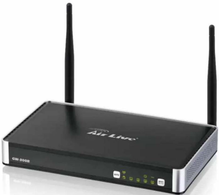
Exterior view of a Air Live network device (no text or symbols on the device body)Congratulations on your purchase of this outstanding Wireless Broadband Router. This product is specifically designed for Small Office and Home Office needs. It provides a complete SOHO solution for Internet surfing, and is easy to configure and operate even for non-technical users. Instructions for installing and configuring this product can be found in this manual. Before you install and use this product, please read this manual carefully for fully exploiting the functions of this product.
1.1 Packing List
| items | Description | Contents | Quantity |
| 1 WiFi | Gigabit Router 1 |  | |
| 2 Power adapter 12V 1A 1 |  | ||
| 3 | CD 1 |  | |
1.2 Spec Summary Table
| Device Interface | ||
| Ethernet WAN RJ-45 | port, 10/100/1000Mbps, auto-MDI/MDIX 1 | |
| Ethernet LAN RJ-45 port | 10/100/1000Mbps, auto-MDI/MDIX 4 | |
| Antenna 3 dBi detachable antenna 2 | ||
| WPS Button For WPS connection 1 | ||
| Wireless Enable/disable | To enable or disable Wireless Radio | 1 |
| LED Indication | Power/Status / WAN / LAN1 ~ LAN4/ WiFi | ● |
| Power Jack | DC Power Jack, powered via external DC 12V/1A switching power adapter | 1 |
| Wireless LAN (WiFi) | ||
| Standard | IEEE 802.11b/g/n compliance | ● |
| SSID | SSID broadcast or in stealth mode | ● |
| Channel | Auto-selection, manually | ● |
| Security | WEP, WPA, WPA-PSK, WPA2, WPA2-PSK | ● |
| WPS | WPS (Wi-Fi Protected Setup) | ● |
| WMM | WMM (Wi-Fi Multimedia) | ● |
| Functionality | ||
| Ethernet WAN | PPPoE, DHCP client, Static IP, PPTP, L2TP | ● |
| WAN Connection | Auto-reconnect, dial-on-demand, manually | ● |
| One-to-Many NAT | Virtual server, special application, DMZ, Super DMZ (IP Passthrough) | ● |
| NAT Session | Support NAT session | 20000 |
| SPI Firewall | IP/Service filter, URL blocking, MAC control | ● |
| DoS Protection | DoS (Deny of Service) detection and protection | ● |
| Routing Protocol | Static route, dynamic route (RIP v1/v2) | ● |
| Management | SNMP, UPnP IGD, syslog, DDNS | ● |
| Administration | Web-based UI, remote login, backup/restore setting | ● |
| Performance | NAT up to 700Mbps and Wireless up to150Mbps | |
| Environment & Certification | ||
| Package Information | Package dimension (mm) | |
| Package weight (g) | ||
| Operation Temp. | Temp.: 0~40oC, Humidity 10%~90% non-condensing | ● |
| Storage Temp. | Temp.: -10~70oC, Humidity: 0~95% non-condensing | ● |
| EMI Certification CE/FCC compliance | ||
| RoHS | RoHS compliance | |
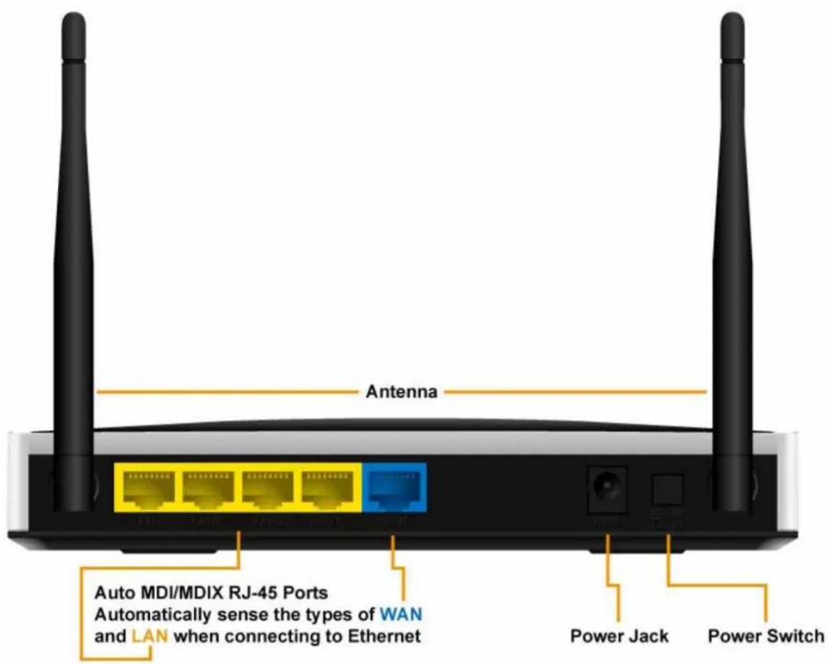
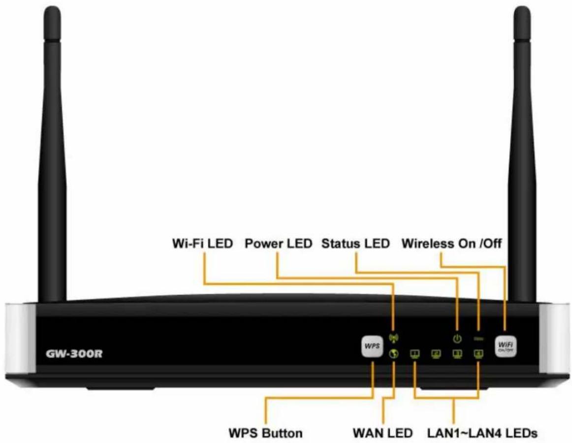
1.3 Hardware Configuration
Figure 2-1 Front Panel
1.4 LED indicators
| LED status Description | ||
| Status Green in flash Device status is working. | ||
| Green RJ45 cable is plugged WAN LED | ||
| Green in flash Data access | ||
| LAN LED | Green RJ45 cable is plugged | |
| Green in flash Data access | ||
| WiFi LED | Green WLAN is on | |
| Green in flash Data access | ||
| Green in fast flash | Device is in WPS PBC mode | |
| Green in dark Wi-Fi Radio is disabled | ||
1.5 Procedure for Hardware Installation
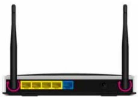
Step 1. Attach the antenna.
1.1. Remove the antenna from its plastic wrapper.
1.2. Screw the antenna in a clockwise direction to the back panel of the unit.
1.3. Once secured, position the antenna upward at its connecting joint.
This will ensure optimal reception.
natural_image
Front view of a black wireless router with two external antennas and control buttons (no visible text or symbols)
- Turn off the Power Switch first.
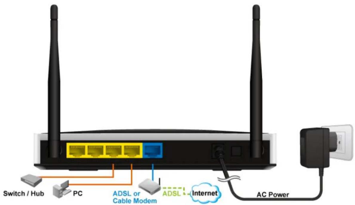
Step 2 Insert the Ethernet cable into LAN Port:
Insert the Ethernet patch cable into LAN port on the back panel of Router, and an available Ethernet port on the network adapter in the computer you will use to configure the unit.
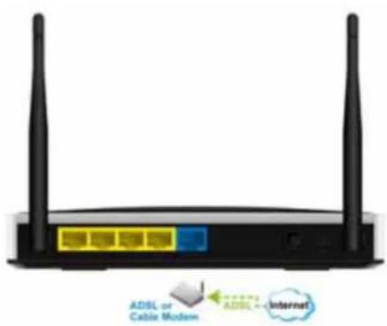
Step 3 Insert the Ethernet patch cable into Wired WAN port:
Insert the Ethernet patch cable form DSL Modem into Wired WAN port on the back panel of Router.
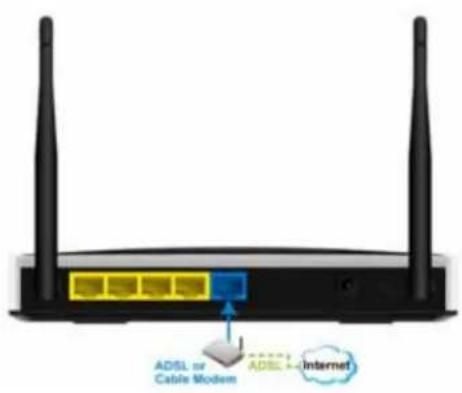
Step 4. Power on Router:
4.1. Connect the power adapter to the receptor on the back panel of your Router and Push Power switch
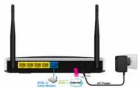
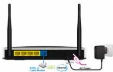
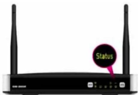
Step 5. Complete the setup.
5.1. When complete, the Status LED will flash.
2
Getting Start
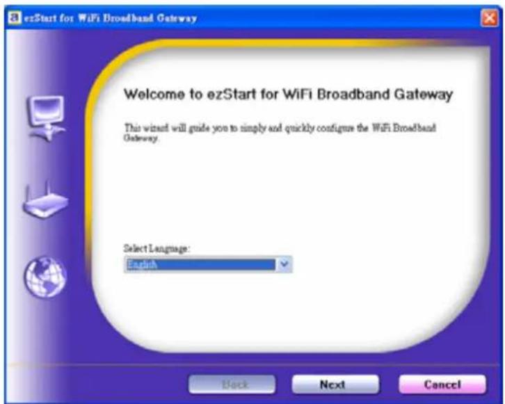
Insert the CD into CD reader on your PC. The program, AutoRun, will be executed automatically. And then you can click the Easy setup Icon for this utility. Configure the settings by the following steps.
2.1. Select Language then click "Next" for continues.
2.2 Setup mode
You can select Wizard mode to run the setup step-by-step or run advanced mode to diagnose the network settings of the router.
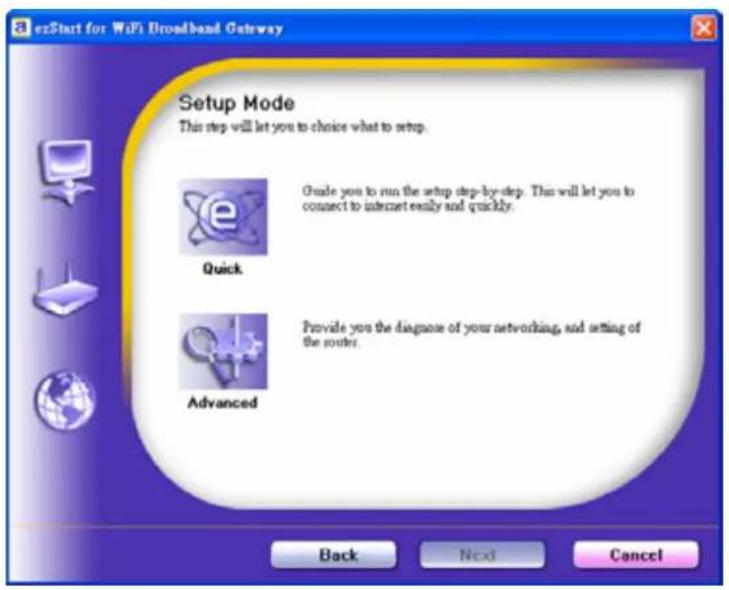
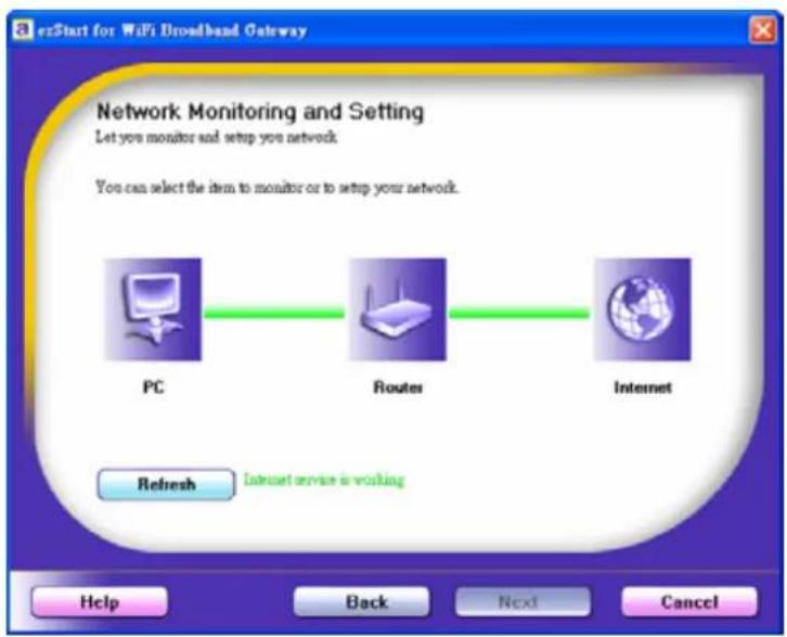
2.3 Advanced mode Setup.
Check the PC, Router or Internet icons for the Status of PC, Router or Internet.
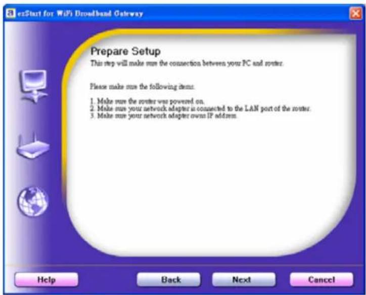
2.4 Quick Wizard Install mode Setup
- Make sure the router is powered on.
- Make sure your network adapter is connected to the LAN port of the router
- Make sure your network adapter has an IP address.
Click "Next" for continues
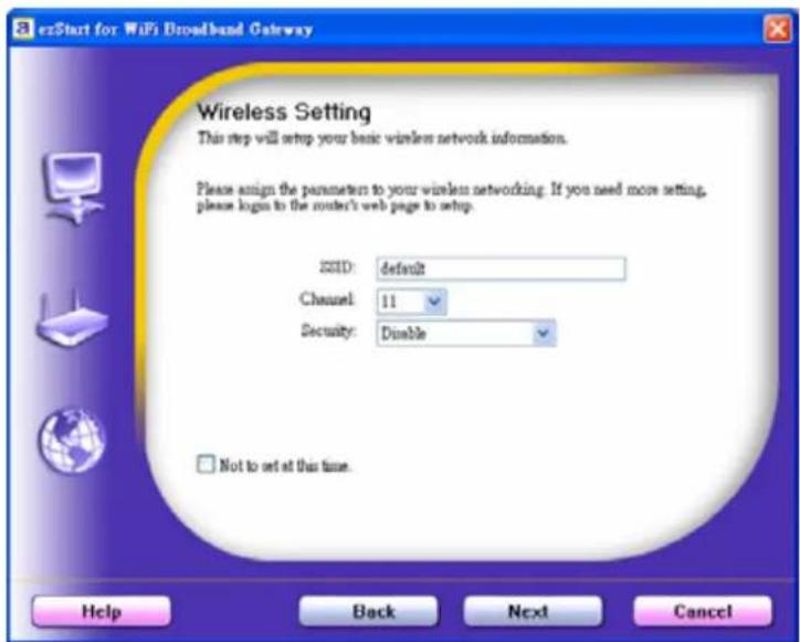
2.5. Wireless Setting.
Key in the SSID, Channel and Security options, and then click "Next" for continues.
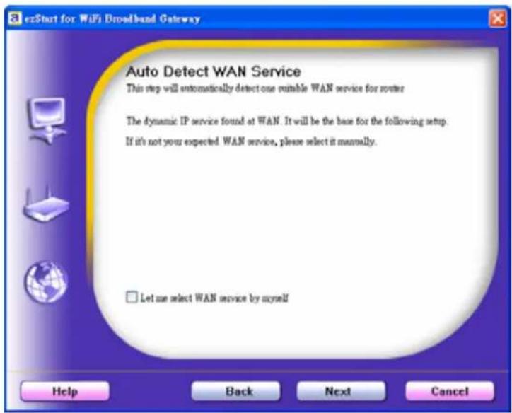
2.6 Auto Detect WAN Service.
Click "Next" for continue.
Click the button, "Let me select WAN service by myself", to disable this function.
Note: The Item supports to detect the Dynamic and PPPoE WAN Services only
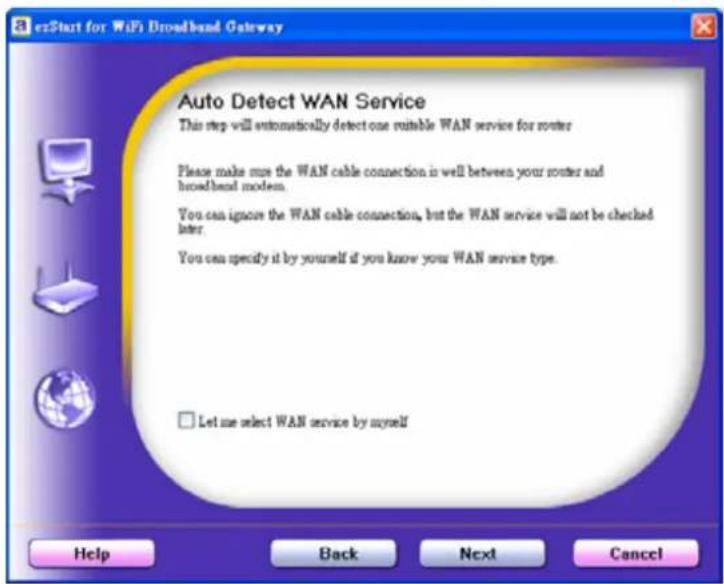
Example, the Dynamic WAN type is detected.
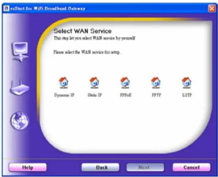
2.7. Manual select WAN Service In the manual mode, Click the any icons for continues.
2.8 Summary of the settings and Next to "Reboot" Click "Next" for continue.
2.9 Apply the Settings or Modify. Click "Next" for continue.
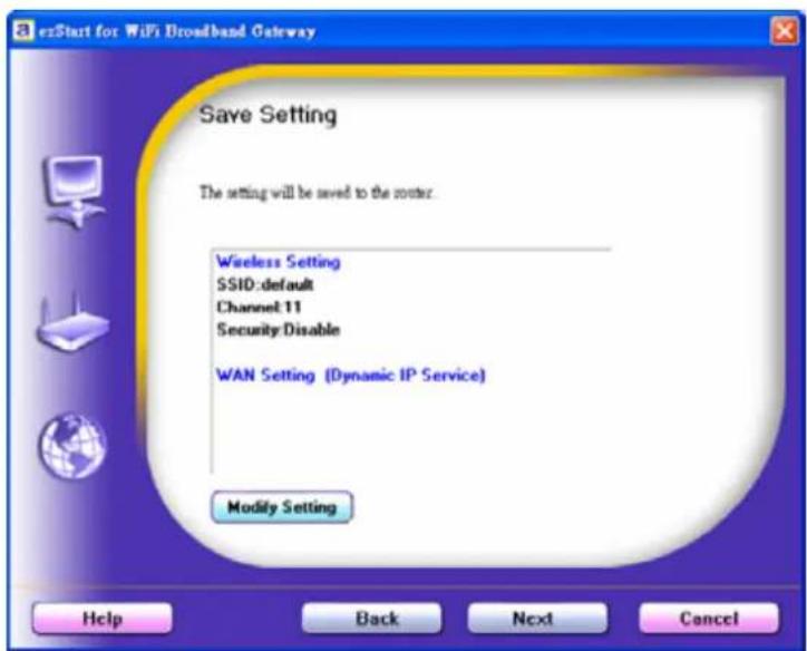
2.10 Test the Internet connection.
Test WAN Networking service. Click "Next" for continue.
You can ignore the by select the "Ignore Test".
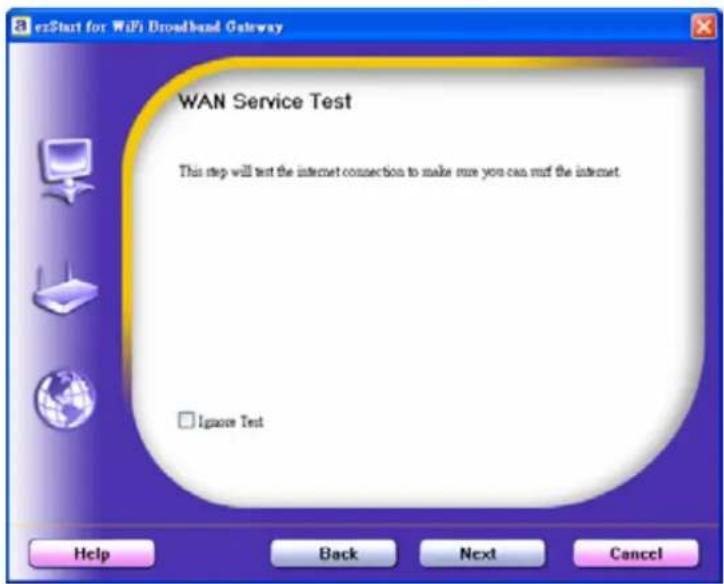
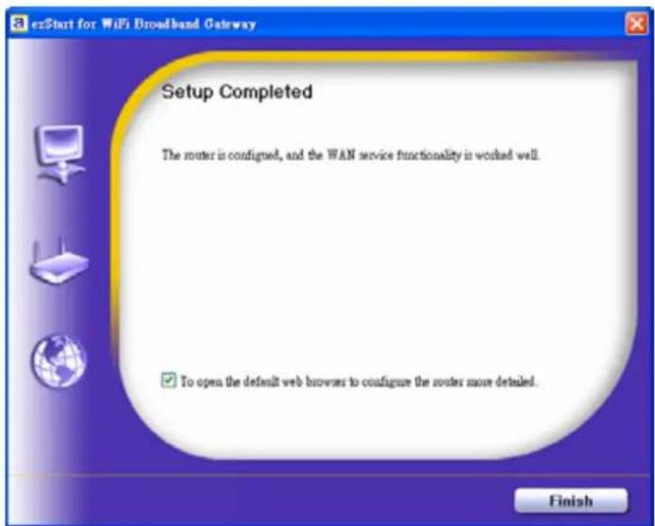
2.11 Setup Completed.
The EzSetup is finish, you can open the default web browser to configure advanced settings of the Router.
Click "Finish" to complete the installation.
3
Making Configuration
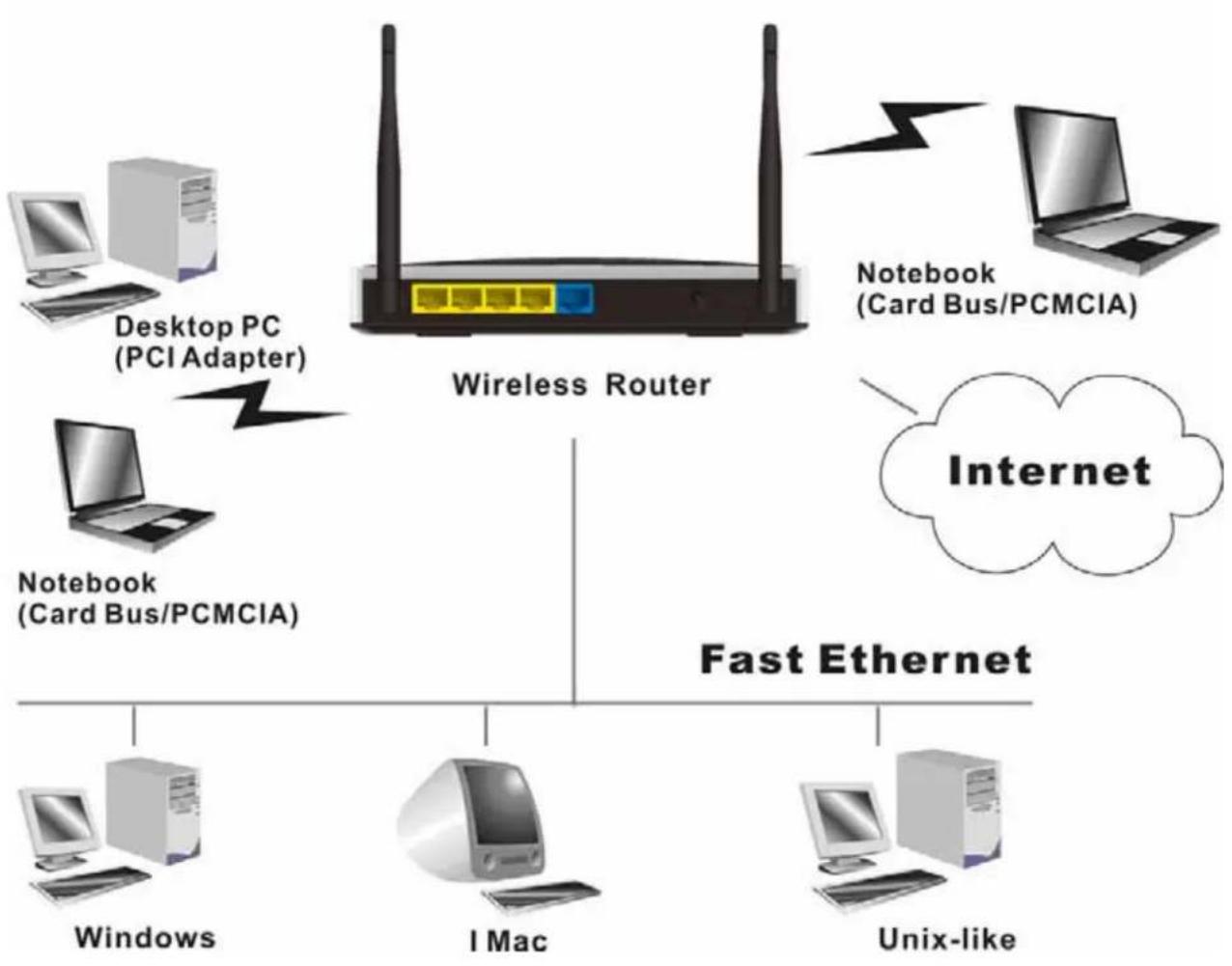
This product provides Web based configuration scheme, that is, configuring by your Web browser, such as Mozilla Firefox or or Internet Explorer. This approach can be adopted in any MS Windows, Macintosh or UNIX based platforms.
flowchart
graph TD
    A["Desktop PC (PCI Adapter)"] --> B["Notebook (Card Bus/PCMCIA)"]
    C["Notebook (Card Bus/PCMCIA)"] --> B
    D["Internet"] --> E["Fast Ethernet"]
    F["Windows"] --> B
    G["I Mac"] --> B
    H["Unix-like"] --> B
    I["Notebook (Card Bus/PCMCIA)"] --> B
    J["Notebook (Card Bus/PCMCIA)"] --> B
    K["Notebook (Card Bus/PCMCIA)"] --> B
3.1 Login to Configure from Wizard
Type in the IP Address (http://192.168.1.254)

Type password, the default is "airlive" and click 'login' button.

Press "Wizard" for basic settings with simple way.
![Air Live ADMINISTRATOR'S MAIN MENU Status Wizard Advanced System Status [HELP] Item WAN Status Sidenote IP Address 192.158.0.154 Static IP Subset Mask 255.255.255.0 Gateway 192.158.0.254 Domain Name Server 158.95.1.1 MAC Address 00-50-18-21-04-57](/content/2026/05/920108/images/b2dd16cc8158612fd8844a0c28e6b28005656b3bf410e29e58764907125c1809.jpg)
Press "Next" to start wizard.
![Air Live® GW-300R Wireless 2T2R 300Mbps Gigas Router ADMINISTRATOR'S MAIN MENU Status Wizard Advanced Logout English Setup Wizard [EXIT] Setup Wizard will guide you through a basic configuration procedure step by step. • Step 1. Setup Login Password • Step 2. WAN Setup • Step 3. Wireless Setup • Step 4. Cumman • Step 5. Finish Start > Password > WAN > Wireless > Summary > Finish! Find >](/content/2026/05/920108/images/5cceb6fcd6f222e3ac624303a6968d46d22c9c5fafa752c5d48f0fea6c3496e0.jpg)
Step 1:
Set up your system password.
![Air Live® GW-300R Wireless 2T2R 300Mbps Giga Router ADMINISTRATOR'S MAIN (MEN) Status Wizard Advanced Logout English Setup Wizard - Setup Logger Password [EXIT] • Old Password • New Password • Recoultion < Back [ Start > Password > WAN > Windows > Summary > Texted ] Next >](/content/2026/05/920108/images/4acace19fc3d297265a4a419af509b99daecc9df76670fbdea400ff23dc85668.jpg)
Step 2:
Select Wan Type.
Auto Detecting or Setup Manually.
![Air Live® GW-300R Wireless ZT2R 300Mbps Giga Router www.airlive.com ADMINISTRATOR'S MAIN MENU Status Wizard Advanced Logout English Setup Wizard - WAN Type Setup [EXIT] Auto Defecting WAN Type Setup WAN Type Manualsly < Back [ Start > Password + WAN > Wireless > Summary > Flight? ] Next >](/content/2026/05/920108/images/88160cfb5ff76fe1f547eb7adea5b49a3ee0ece4d662ad99efd8f98a9261b43b.jpg)
![Air Live® GW-300R Wireless 2T2R 300Mbps Giga Router UA ADMINISTRATOR'S MAIN MENU Status Wizard Advanced Logical English Setup Wizard - Select WAN Type [EXIT] ISP assigns you a static IP address. (Static IP Address) Obtain an IP address from ISP automatically. (Dynamic IP Address) Dynamic IP Address with Road Runner Session Management, (e.g. TikTok BigPond) Some ISPs require the use of PPPoE to connect to their services. (PPP over Ethernet) Some ISP's require the use of PPTF to connect to their services. (PPTF) Some ISP's require the use of L2TP to connect to their services. (L2TP) < Back [ Start > Password > WAN > Wireless > Summary > Excel ] Next >](/content/2026/05/920108/images/c2467b2b8b2a92f5f25622b80eda54a7db91d3ce179cf77ded2ac0d5e9240240.jpg)
Step 3:
Setup the LAN IP and WAN Type.
![Air Live GW-300R Wireless 272R 300Mbps Giga Router ADMINISTRATOR'S MAIN MENU Status Wizard Advanced Logext English Setup Wizard - WAN Settings - Dynamic IP Address [EXIT] • LAN IP Address 192.168.1.254 Host Name (optional) • WAN's MAC Address 00-50-18-21-D4-67 Close MAC < Back { Start > Password > WAN > Wireless > Summary > Finan: { Next >](/content/2026/05/920108/images/bcaa5fed17cabcde67f004c35137d9b61397f5900af1d2fc38d28e01c48fc8e0.jpg)
Step 4:
Please fill in PPPoE service information which is provided by your ISP.
Example:
![Air Live® GW-300R Wireless 2T2R 300Mbps Giga Router www.airlive.com Administrator's MAIN (MAIN) Status Wizard Advanced Layout English Setup Wizard - WAN Settings - PPP over Ethernet [EXIT] • LAN IP Address 192.168.1.254 • Account • Password • Primary DNS 0.0.0.0 • Secondary DNS 0.0.0.0 • PPPoE Service Name (optional) • Assigned IP Address 0.0.0.0 (optional) < Back [ Start > Password > WAN > Wireless > Summary > Print] Next >](/content/2026/05/920108/images/52e63015570144264c948eb7f010201df4bd20be556e5e5463b7201ea322e6b9.jpg)
Step 5:
Set up your Wireless.
![Air Live® GW-300R Wireless 2T2R 300Mbps Giga Router www.airlive.com ADMINISTRATOR'S MAIN MENU Status Wizard Advanced - Layout English Setup Wizard - Wireless settings [EXIT] • Wireless function Enabling Enable • Network ID (SBID) default • Channel 11 < Back { Start > Password > Web > Wireless > Summary > Cookie } Next >](/content/2026/05/920108/images/be0ec3efa663f9328faa470b996ab8a410bce778a6ae69a3ff03b22d4ee33d89.jpg)
Set up your Authentication and Encryption.
![Air Live® GW-300R Wireless 2T2R 300Maps Giga Router www.ahlive.com US ADMINISTRATOR'S NAME MENU Status Wizard Advanced Logout English Setup Wizard - Wireless Security [EXIT] • Security • IEP • Key 1 • Key 2 • Key 3 • Key 4 #EIP 54 bits 126 bits ○ ○ ○ ○ Please condition 26 for 128bits or 10 for 64 bits hexadecimal (i), 1, 2,..., (i, A, B,...) digits. < Back [ Start > Password] < Web > Wireless > Summary > Initiat > Next >](/content/2026/05/920108/images/3eaa4a0a945093d2597f2bb2c2a5ec256c15b80956dcf0463bf42b6e13c90804.jpg)
Step 6: Then click Apply Setting. And then the device will reboot.
![Air Live® GW-300R Wireless 2T2R 300Mbps Giga Router ADMINISTRATOR'S MAIN MENU Status Wizard Advanced Logout English Setup Wizard - Summary [EXIT] Please confirm the information below. [ WAN Setting ] WAN Type Dynamic IP Address Host Name - WAN's MAC Address 00-50-18-21-04-57 [ Wireless Setting ] Wireless Enable SSID default Channel 11 Security None Do you want to proceed the network testing? < Back [ Start > Password > WAN > Wireless > Summare > Project ] Apply Settings](/content/2026/05/920108/images/ccc0c38e7515dc2fc2d1fe37732ab3fdfccce20f050a959e8c4722ebcf530b05.jpg)
Step 7: Click Finish to complete it.
![Air Live® GW-300R Wireless 2T2R 300Mbps Giga Router www.airlive.com ADMINISTRATOR'S MAIN HERE! Status Wizard Advanced Logout English Setup Wizard [EXIT] Configuration is Completed. Please click "Finish" to back to Status page. Do you can click "Configure Again" to setup the wizard again. Configure Again [Start > Password > WBA > Windows > Summary > Finish] Finish](/content/2026/05/920108/images/7fed6bad37291aaf0003110eaad86b035e8b8c453305cab6396c11c05fc57350.jpg)
3.2 System Status
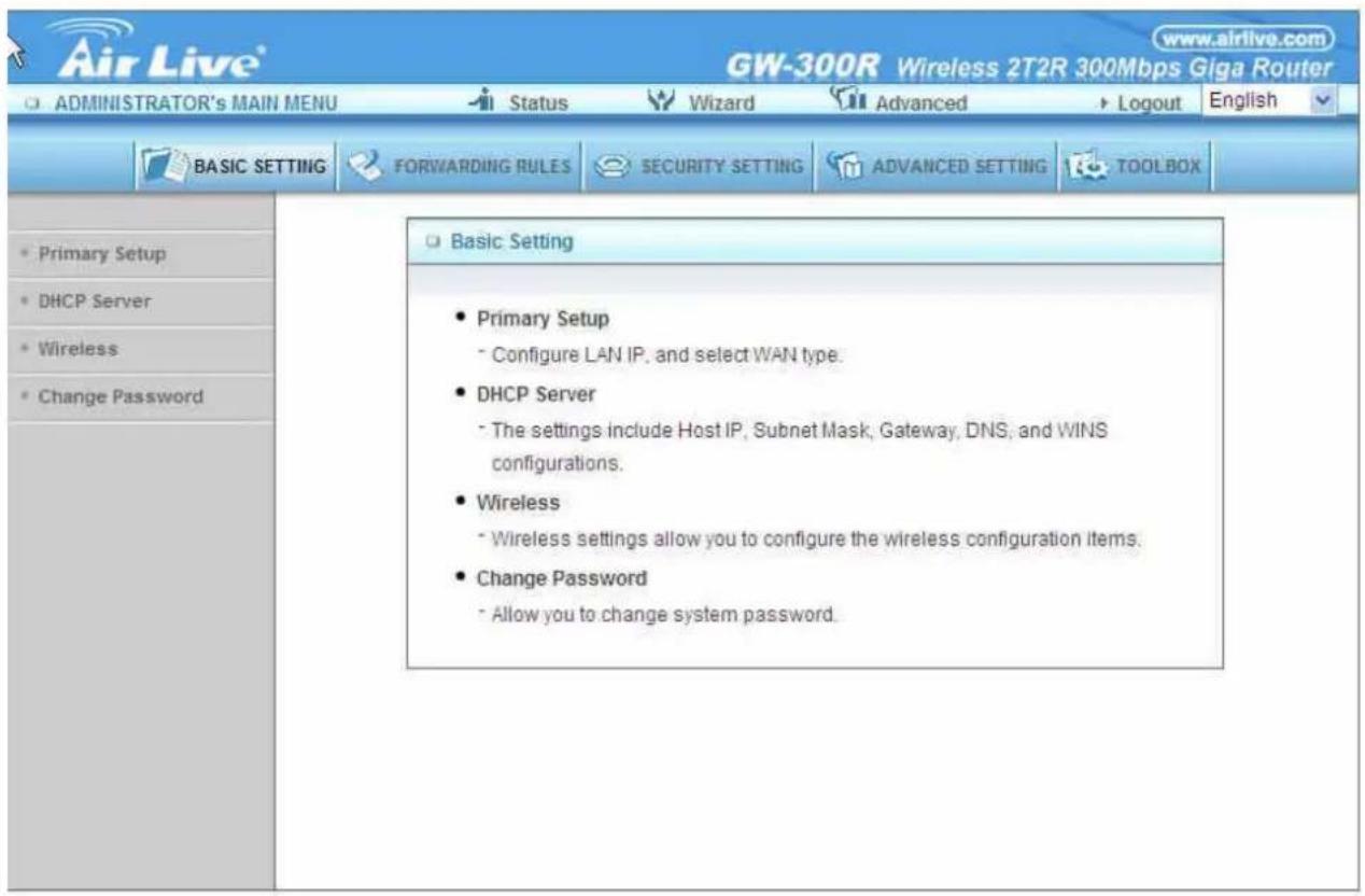
This option provides the function for observing this product's working status:
WAN Port Status.
If the WAN port is assigned a dynamic IP, there may appear a "Renew" or "Release" button on the Sidenote column. You can click this button to renew or release IP manually.
Statistics of WAN: enables you to monitor inbound and outbound packets
3.3 Advanced
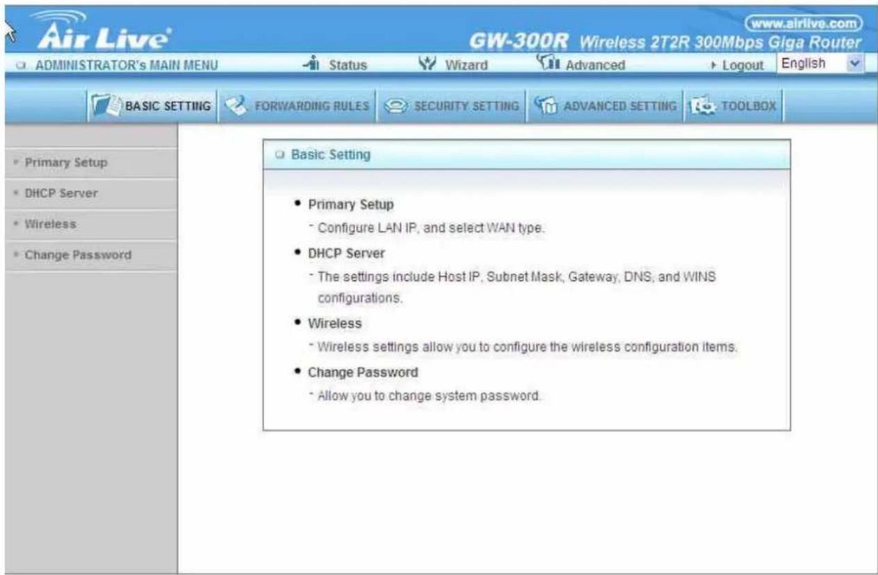
3.3.1 Basic Setting
Please Select "Advanced Setup" to Setup
3.3.1.1 Primary Setup – WAN Type, Virtual Computers
Press "Change"
![Air Live® GW-300R Wireless 2T2R 300Mbps Giga Router ADMINISTRATOR'S MAIN MENU Status Wizard Advanced Logout English BASIC SETTING FORWARDING RULES SECURITY SETTING ADVANCED SETTING TOOLBOX Primary Setup [HELP] Item Setting LAN IP Address 192.168.1.254 WAN Type Dynamic IP Address Change... Host Name (optional) WAN's MAC Address 00-50-18-21-D4-57 Clone MAC Renew IP Forever Enable (Auto-reconnect) IGMP Enable Save Undo Virtual Computers... Reboot Saved! The change doesn't take effect until router is rebooted.](/content/2026/05/920108/images/c2e5a3f692fa31de2937e7b80ebf75f4cd031ccfed3177fc1eaf22fb8fec6d23.jpg)
This option is primary to enable this product to work properly. The setting items and the web appearance depend on the WAN type. Choose correct WAN type before you start. LAN IP Address: the local IP address of this device. The computers on your network must use the LAN IP address of your product as their Default Gateway. You can change it if necessary.
| Primary Setup [HELP] | |
| Item | Setting |
| LAN IP Address | 192.168.1.254 |
WAN Type: WAN connection type of your ISP. You can click Change button to choose a correct one from the following four options:
Static IP Address: ISP assigns you a static IP address.
Dynamic IP Address: Obtain an IP address from ISP automatically.
PPP over Ethernet: Some ISPs require the use of PPPoE to connect to their services.
PPTP: Some ISPs require the use of PPTP to connect to their services.
F. L2TP: Some ISPs require the use of L2TP to connect to their services
Static IP Address: ISP assigns you a static IP address:
WAN IP Address, Subnet Mask, Gateway, Primary and Secondary DNS: enter the proper setting provided by your ISP.
![ADMINISTRATOR's MAIN MENU Status Wizard Advanced Logout English BASIC SETTING FORWARDING RULES SECURITY SETTING ADVANCED SETTING TOOLBOX Primary Setup [HELP] Item Setting LAN IP Address 192.168.1.254 WAN Type Static IP Address Change... WAN IP Address 0.0.0.0 WAN Subnet Mask 255.255.255.0 WAN Gateway 0.0.0.0 Primary DNS 0.0.0.0 Secondary DNS 0.0.0.0 IGMP Enable Save Undo Virtual Computers... Reboot Saved! The change doesn't take effect until router is rebooted.](/content/2026/05/920108/images/f41773266224cd035b286cac7b65a885703bfd59bcfa2f967e6e3c716aa1cfa5.jpg)
Dynamic IP Address: Obtain an IP address from ISP automatically.
Host Name: optional. Required by some ISPs, for example, @Home.
Renew IP Forever: this feature enables this product to renew your IP address automatically when the lease time is expiring-- even when the system is idle.
![ADMINISTRATOR's MAIN MENU Status Wizard Advanced Logout English BASIC SETTING FORWARDING RULES SECURITY SETTING ADVANCED SETTING TOOLBOX Primary Setup [HELP] Item Setting LAN IP Address 192.168.1.254 WAN Type Dynamic IP Address Change... Host Name (optional) WAN's MAC Address 00-50-18-21-D4-57 Clone MAC Renew IP Forever Enable (Auto-reconnect) IGMP Enable Save Undo Virtual Computers... Reboot Saved! The change doesn't take effect until router is rebooted.](/content/2026/05/920108/images/7d7d34e63ce48b9f4e1abf61737bdc2736a7fca956523783246d3cab55a81cc2.jpg)
PPP over Ethernet: Some ISPs require the use of PPPoE to connect to their services. PPPoE Account and Password: the account and password your ISP assigned to you. For security, this field appears blank. If you don't want to change the password, leave it empty. PPPoE Service Name: optional. Input the service name if your ISP requires it. Otherwise, leave it blank.
Maximum Idle Time: the amount of time of inactivity before disconnecting your PPPoE session.
Set it to zero or enable Auto-reconnect to disable this feature.
Maximum Transmission Unit (MTU): Most ISP offers MTU value to users. The most common MTU value is 1492.
Connection Control: There are 3 modes to select:
Connect-on-demand: The device will link up with ISP when the clients send outgoing packets.
Auto-Reconnect(Always-on): The device will link with ISP until the connection is established.
Manually : The device will not make the link until someone clicks the connect-button in the Staus-page.
![ADMINISTRATOR's MAIN MENU Status Wizard Advanced Logout English BASIC SETTING FORWARDING RULES SECURITY SETTING ADVANCED SETTING TOOLBOX Primary Setup [HELP] Item Setting LAN IP Address 192.168.1.254 WAN Type PPP over Ethernet Change... PPPoE Account PPPoE Password Primary DNS 0.0.0.0 Secondary DNS 0.0.0.0 Maximum Idle Time 300 seconds Connection Control Connect-on-demand PPPoE Service Name (optional) Assigned IP Address 0.0.0.0 (optional) MTU 1492 IGMP Enable Save Undo Reboot Saved! The change doesn't take effect until router is rebooted.](/content/2026/05/920108/images/0bb4e454d224f3273a3e5888c77dcf1c086e2a1393e9d18ff9b1bbea336488cf.jpg)
PPTP: Some ISPs require the use of PPTP to connect to their services
First, Please check your ISP assigned and Select Static IP Address or Dynamic IP Address.
-
My IP Address and My Subnet Mask: the private IP address and subnet mask your ISP assigned to you.
-
Server IP Address: the IP address of the PPTP server.
-
PPTP Account and Password: the account and password your ISP assigned to you. If you don't want to change the password, keep it empty.
-
Connection ID: optional. Input the connection ID if your ISP requires it.
-
Maximum Idle Time: the time of no activity to disconnect your PPTP session. Set it to zero or enable Auto-reconnect to disable this feature. If Auto-reconnect is enabled, this product will connect to ISP automatically, after system is restarted or connection is dropped.
Connection Control: There are 3 modes to select:
Connect-on-demand: The device will link up with ISP when the clients send outgoing packets.
Auto-Reconnect(Always-on): The device will link with ISP until the connection is established.
Manually: The device will not make the link until someone clicks the connect-button in the Staus-page.
![Primary Setup DHCP Server Wireless Change Password Primary Setup [ HELP ] Item Setting LAN IP Address 192.168.1.254 WAN Type pptp Change... IP Mode Static IP Address My IP Address 0.0.0.0 My Subnet Mask 255.255.255.0 Gateway IP 0.0.0.0 Server IP Address/Name PPTP Account PPTP Password Connection ID (optional) Maximum Idle Time 300 seconds Connection Control Connect-on-demand MTU 1460 IGMP Enable Save Undo Reboot Saved! The change doesn't take effect until router is rebooted.](/content/2026/05/920108/images/d92d445d196ebdd67e78319c3b3b83acce4929eee4215d9d1ae55ca74629f8bd.jpg)
L2TP: Some ISPs require the use of L2TP to connect to their services
First, Please check your ISP assigned and Select Static IP Address or Dynamic IP Address.
For example: Use Static
- My IP Address and My Subnet Mask: the private IP address and subnet mask your ISP assigned
to you.
- Server IP Address: the IP address of the PPTP server.
- PPTP Account and Password: the account and password your ISP assigned to you. If you don't
want to change the password, keep it empty.
- Connection ID: optional. Input the connection ID if your ISP requires it.
- Maximum Idle Time: the time of no activity to disconnect your PPTP session. Set it to zero or enable Auto-reconnect to disable this feature. If Auto-reconnect is enabled, this product will connect to ISP automatically, after system is restarted or connection is dropped.
Connection Control: There are 3 modes to select:
Connect-on-demand: The device will link up with ISP when the clients send outgoing packets.
Auto-Reconnect(Always-on): The device will link with ISP until the connection is established.
Manually :The device will not make the link until someone clicks the connect-button in the Staus-page.
![BASIC SETTING FORWARDING RULES SECURITY SETTING ADVANCED SETTING TOOLBOX Primary Setup [ HELP ] Item Setting LAN IP Address 192.168.1.254 WAN Type L2TP Change... IP Mode Static IP Address IP Address 0.0.0.0 Subnet Mask 255.255.255.0 WAN Gateway IP 0.0.0.0 Server IP Address/Name L2TP Account L2TP Password Maximum Idle Time 300 seconds Connection Control Connect-on-demand MTU 1460 IGMP Enable Save Undo Reboot Saved! The change doesn't take effect until router is rebooted.](/content/2026/05/920108/images/bb788401d3cdbc4f5f030bed1ef0afd2cf8d7d3ce90ae60383977dc962bcb0fa.jpg)
Virtual Computers(Only for Static and dynamic IP address Wan type)
![ADMINISTRATOR'S MAIN MENU Status Wizard Advanced Logout English BASIC SETTING FORWARDING RULES SECURITY SETTING ADVANCED SETTING TOOLBOX Virtual Computers [HELP] DHCP clients --- Select one --- Copy to ID -- ID Global IP Local IP Enable 1 192.168.1 2 192.168.1 3 192.168.1 4 192.168.1 5 192.168.1 Allow you to. setup the one-to- one mapping of multiple global IP address and local IP address. Save Undo](/content/2026/05/920108/images/50f0727f52c130005e16a512991c50e981eaff12f6c467a03e075938ff15e2a4.jpg)
Virtual Computer enables you to use the original NAT feature, and allows you to setup the one-to-one mapping of multiple global IP address and local IP address.
Global IP: Enter the global IP address assigned by your ISP.
Local IP: Enter the local IP address of your LAN PC corresponding to the global IP address.
Enable: Check this item to enable the Virtual Computer feature.
3.3.1.2 DHCP Server
![BASIC SETTING FORWARDING RULES SECURITY SETTING ADVANCED SETTING TOOLBOX • Primary Setup • DHCP Server • Wireless • Change Password DHCP Server [HELP] Item Setting • DHCP Server Disable Enable • Lease Time 0 Minutes • IP Pool Starting Address 100 • IP Pool Ending Address 199 • Domain Name • Primary DNS 0.0.0.0 • Secondary DNS 0.0.0.0 • Primary WINS 0.0.0.0 • Secondary WINS 0.0.0.0 • Gateway 0.0.0.0 (optional) Save Undo Clients List...](/content/2026/05/920108/images/e2c3bf333fb93a823babfc009acd71fad931b32d101a35bbe47d8914684c8587.jpg)
Press "More>>"
DHCP Server: Choose "Disable" or "Enable."
Lease time: This is the length of time that the client may use the IP address it has been Assigned by dhcp server.
IP pool starting Address/ IP pool starting Address: Whenever there is a request, the DHCP server will automatically allocate an unused IP address from the IP address pool to the requesting computer. You must specify the starting and ending address of the IP address pool.
Domain Name: Optional, this information will be passed to the client.
Primary DNS/Secondary DNS: This feature allows you to assign DNS Servers
Primary WINS/Secondary WINS: This feature allows you to assign WINS Servers
Gateway: The Gateway Address would be the IP address of an alternate Gateway.
This function enables you to assign another gateway to your PC, when DHCP server offers an IP to your PC.
DHCP Client List:
![BASIC SETTING FORWARDING RULES SECURITY SETTING ADVANCED SETTING TOOLBOX • Primary Setup • DHCP Server • Wireless • Change Password DHCP Clients List [HELP] IP Address Host Name MAC Address Select 192.168.1.199 airlive-WayneNB 00-16-D4-EB-06-FC Wake up Delete Back Refresh](/content/2026/05/920108/images/3c3b3b775c5c706fefb5d5491471cc4ffa744fe72f0f2ac38f38cc24f0a01e75.jpg)
.3.1.3 Wireless 3
![ADMINISTRATOR'S MAIN MENU Status Wizard Advanced Logout English BASIC SETTING FORWARDING RULES SECURITY SETTING ADVANCED SETTING TOOLBOX Primary Setup DHCP Server Wireless Change Password Wireless Setting [HELP] Item Setting Wireless Enable Disable Turn off Wireless depend as Schedule Rule (00)Always Enable Disable Schedule Setting Network ID(SSID) default Wireless Mode Mixed mode 11g only 11b only 11n only SSID Broadcast Enable Disable Channel 11 WDS Enter... WPS Enter... Security None Save Undo Wireless Client List...](/content/2026/05/920108/images/5ffee26c39b9cc552536acc975d6deff51276203ab822be542ac0c2b92d60359.jpg)
Wireless settings allow you to set the wireless configuration items.
Wireless : The user can enable or disalbe wireless function.
Wireless On/Off by time Schedule: The device can turn off Wireless depend as Schedule.
Network ID (SSID): Network ID is used for identifying the Wireless LAN (WLAN). Client stations can roam freely over this product and other Access Points that have the same Network ID. (The factory setting is “default”)
SSID Broadcast: The router will Broadcast beacons that have some information, including ssid so that the wireless clients can know how many ap devices by scanning function in the network. Therefore, this function is disabled, the wireless clients can not find the device from beacons.
Channel: The radio channel number. The permissible channels depend on the Regulatory Domain.
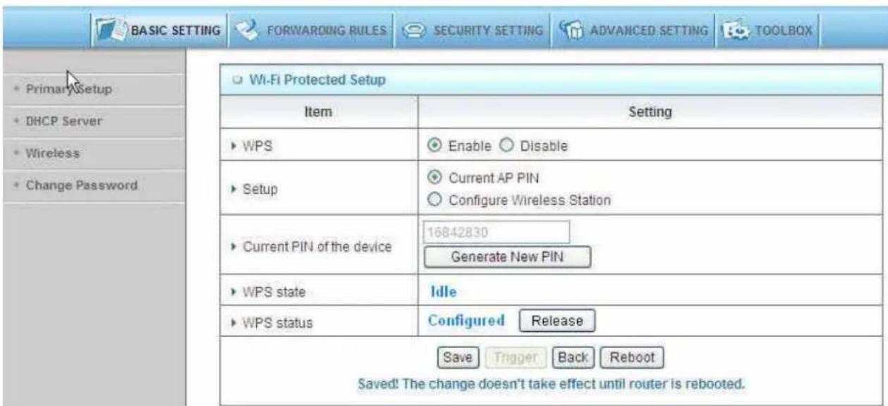
WPS (WiFi Protection Setup)
WPS is WiFi Protection Setup which is similar to WCN-NET and offers safe and easy way in Wireless Connection.
WDS(Wireless Distribution System)
WDS operation as defined by the IEEE802.11 standard has been made available. Using WDS it is possible to wirelessly connect Access Points, and in doing so extend a wired infrastructure to locations where cabling is not possible or inefficient to implement.
Hybrid Mode
It means the device can support WDS and AP Mode simultaneously.
![ADMINISTRATOR's MAIN MENU Status Wizard Advanced Logout English BASIC SETTING FORWARDING RULES SECURITY SETTING ADVANCED SETTING TOOLBOX Primary Setup DHCP Server Wireless Change Password It is a system that enables the interconnection of access points wirelessly. WDS Setting [HELP] Item Setting AP Mode: AP Only Remote AP MAC MAC 1 MAC 2 MAC 3 MAC 4 Scanned AP's MAC --- Select one --- Copy to Remote AP MAC -- SSID Channel MAC Address CL-WLAN 1 00-1A-1E-C6-5C-90 CL-GUEST 1 00-1A-1E-C6-5C-91 wmu6500 1 00-4F-67-03-B0-29 Air3G_Sam 1 00-4F-62-2A-06-4C CL-WLAN 1 00-1A-1E-8B-95-C1](/content/2026/05/920108/images/e3a9e24a19ce7ed43c69bbf717c03796cb669cf584894fd171899d2466dd00ba.jpg)
Security: Select the data privacy algorithm you want. Enabling the security can protect your data while it is transferred from one station to another.
There are several security types to use:
WEP :
When you enable the 128 or 64 bit WEP key security, please select one WEP key to be used and input 26 or 10 hexadecimal (0, 1, 2...8, 9, A, B...F) digits.
802.1X
Check Box was used to switch the function of the 802.1X. When the 802.1X function is enabled, the Wireless user must authenticate to this router first to use the Network service.
RADIUS Server
IP address or the 802.1X server's domain-name.
RADIUS Shared Key
Key value shared by the RADIUS server and this router. This key value is consistent with the key value in the RADIUS server.
![ADMINISTRATOR's MAIN MENU Status Wizard Advanced Logout English BASIC SETTING FORWARDING RULES SECURITY SETTING ADVANCED SETTING TOOLBOX Primary Setup DHCP Server Wireless Change Password Wireless Setting [HELP] Item Setting ► Wireless Enable Disable ► Turn off Wireless depend as Schedule Rule (00)Always Enable Disable Schedule Setting ► Network ID(SSID) default ► Wireless Mode Mixed mode 11g only 11b only 11n only ► SSID Broadcast Enable Disable ► Channel 11 ► WDS Enter... ► WPS Enter... ► Security 802.1x and RADIUS ► Encryption Key Length 64 bits 128 bits ► RADIUS Server IP 0.0.0.0 ► RADIUS port 1812 ► RADIUS Shared Key Save Undo Wireless Client List...](/content/2026/05/920108/images/6984673ab0afc000d322d9b9f5b3b0ae442434383f32700bbee3d0367654c316.jpg)
WPA-PSK
- Select Encryption and Pre-share Key Mode
If you select HEX, you have to fill in 64 hexadecimal (0, 1, 2...8, 9, A, B...F) digits
If ASCII, the length of pre-share key is from 8 to 63.
2. Fill in the key, Ex 12345678
![ADMINISTRATOR'S MAIN MENU Status Wizard Advanced Logout English BASIC SETTING FORWARDING RULES SECURITY SETTING ADVANCED SETTING TOOLBOX Primary Setup DHCP Server Wireless Change Password Wireless Setting [HELP] Item Setting ► Wireless Enable Disable ► Turn off Wireless depend as Schedule Rule (00)Always Enable Disable Schedule Setting ► Network ID(SSID) default ► Wireless Mode Mixed mode 11g only 11b only 11n only ► SSID Broadcast Enable Disable ► Channel 11 ► WDS Enter... ► WPS Enter... ► Security WPA-PSK ► Encryption TKIP AES ► Preshare Key Mode ASCII ► Preshare Key Save Undo Wireless Client List...](/content/2026/05/920108/images/3842a06ba76b40b18657a9cf48c6984777ce1fad2067e576c5853eea5c3884f8.jpg)
WPA
Check Box was used to switch the function of the WPA. When the WPA function is enabled, the Wireless user must authenticate to this router first to use the Network service. RADIUS Server IP address or the 802.1X server's domain-name.
Select Encryption and RADIUS Shared Key
If you select HEX, you have to fill in 64 hexadecimal (0, 1, 2...8, 9, A, B...F) digits If ASCII, the length of pre-share key is from 8 to 63.
Key value shared by the RADIUS server and this router. This key value is consistent with the key value in the RADIUS server.
WPA2-PSK(AES)
- Select Pre-share Key Mode
If you select HEX, you have to fill in 64 hexadecimal (0, 1, 2...8, 9, A, B...F) digits If ASCII, the length of Pre-share key is from 8 to 63.
- Fill in the key, Ex 12345678
WPA2(AES)
Check Box was used to switch the function of the WPA. When the WPA function is enabled, the Wireless user must authenticate to this router first to use the Network service. RADIUS Server
IP address or the 802.1X server's domain-name.
Select RADIUS Shared Key
If you select HEX, you have to fill in 64 hexadecimal (0, 1, 2...8, 9, A, B...F) digits If ASCII, the length of Pre-share key is from 8 to 63.
Key value shared by the RADIUS server and this router. This key value is consistent with the key value in the RADIUS server.
WPA-PSK /WPA2-PSK
The router will detect automatically which Security type the client uses to encrypt.
- Select Pre-share Key Mode
If you select HEX, you have to fill in 64 hexadecimal (0, 1, 2...8, 9, A, B...F) digits If ASCII, the length of Pre-share key is from 8 to 63.
- Fill in the key, Ex 12345678
![ADMINISTRATOR's MAIN MENU Status Wizard Advanced Logout English BASIC SETTING FORWARDING RULES SECURITY SETTING ADVANCED SETTING TOOLBOX Printhe Setup DHCP Server Wireless Change Password Wireless Setting [HELP] Item Setting ► Wireless Enable Disable ► Turn off Wireless depend as Schedule Rule (00)Always Enable Disable Schedule Setting ► Network ID(SSID) default ► Wireless Mode Mixed mode 11g only 11b only 11n only ► SSID Broadcast Enable Disable ► Channel 11 ► WDS Enter... ► WPS Enter... ► Security WPA-PSK / WPA2-PSK ► Encryption TKIP + AES ► Preshare Key Mode ASCII ► Preshare Key Save Undo Wireless Client List...](/content/2026/05/920108/images/a70b9580e1bd9bea0f39e11791e585d1ec87bd6b5d6d760afb748e2e670b6a28.jpg)
WPA/WPA2
Check Box was used to switch the function of the WPA. When the WPA function is enabled, the Wireless user must authenticate to this router first to use the Network service. RADIUS Server
The router will detect automatically which Security type(Wpa-psk version 1 or 2) the client uses to encrypt.
IP address or the 802.1X server's domain-name.
Select RADIUS Shared Key
If you select HEX, you have to fill in 64 hexadecimal (0, 1, 2...8, 9, A, B...F) digits If ASCII, the length of Pre-share key is from 8 to 63.
Key value shared by the RADIUS server and this router. This key value is consistent with the key value in the RADIUS server.
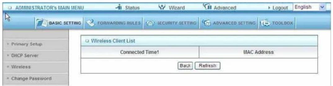
Wireless Client List
.3.1.4 Change Password 3
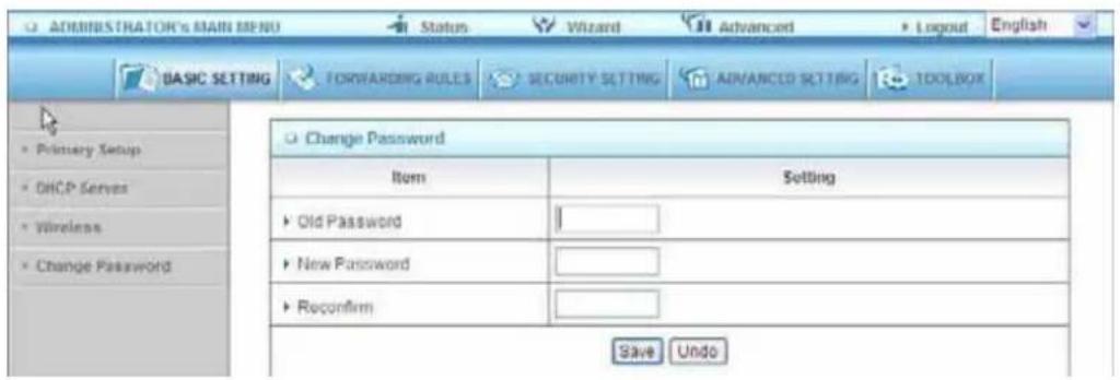
You can change Password here. We strongly recommend you to change the system password for security reason.
3.3.2 Forwarding Rules
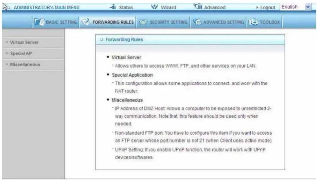
.3.2.1 Virtual Server 3
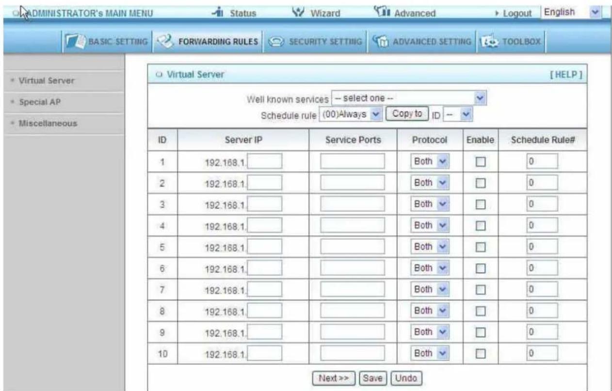
This product's NAT firewall filters out unrecognized packets to protect your Intranet, so all hosts behind this product are invisible to the outside world. If you wish, you can make some of them accessible by enabling the Virtual Server Mapping.
A virtual server is defined as a Service Port, and all requests to this port will be redirected to the computer specified by the Server IP. Virtual Server can work with Scheduling Rules, and give user more flexibility on Access control. For Detail, please refer to Scheduling Rule.
3.3.2.2 Special AP
![ADMINISTRATOR'S MAIN MENU Status Wizard Advanced Logout English BASIC SETTING FORWARDING RULES SECURITY SETTING ADVANCED SETTING TOOLBOX Special Applications [HELP] Popular applications -- Select one -- Copy to ID -- ID Trigger Incoming Ports Enable 1 __________________ 2 __________________ 3 __________________ 4 __________________ 5 __________________ 6 __________________ 7 __________________ 8 __________________ Save Undo](/content/2026/05/920108/images/f65b7fe4295be4d605ced792c72465a2892b9e2e75e60bd268090e89b7e51547.jpg)
Some applications require multiple connections, like Internet games, Video conferencing, Internet telephony, etc. Because of the firewall function, these applications cannot work with a pure NAT router. The Special Applications feature allows some of these applications to work with this product. If the mechanism of Special Applications fails to make an application work, try setting your computer as the DMZ host instead.
Trigger: the outbound port number issued by the application..
Incoming Ports: when the trigger packet is detected, the inbound packets sent to the specified port numbers are allowed to pass through the firewall.
This product provides some predefined settings Select your application and click Copy to to add the predefined setting to your list.
Note! At any given time, only one PC can use each Special Application tunnel.
3.3.2.3 Miscellaneous Items
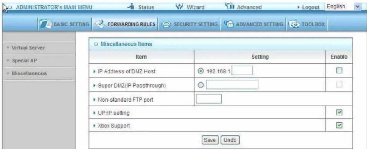
IP Address of DMZ Host
DMZ (DeMilitarized Zone) Host is a host without the protection of firewall. It allows a computer to be exposed to unrestricted 2-way communication for Internet games, Video conferencing, Internet telephony and other special applications.
NOTE: This feature should be used only when needed.
Super DMZ (IP Passthrough)
Super DMZ (IP Passthrough) is a useful feature if a host computer or server on the Local Area Network needs to have access into it from the internet with a real public IP address. With IP Passthrough configured, all IP traffic, not just TCP/UDP, is forwarded back to the host computer. This can be necessary with certain types of software that do not function reliably through Network Address Translation.
Non-standard FTP port
You have to configure this item if you want to access an FTP server whose port number is not 21. This setting will be lost after rebooting.
Xbox Support
The Xbox is a video game console produced by Microsoft Corporation. Please enable this function when you play games.
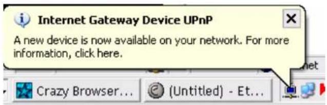
UpnP Setting
The device also supports this function. If the OS supports this function enable it, like Windows Xp. When the user get ip from Device and will see icon as below:
3.3.3 Security Settings
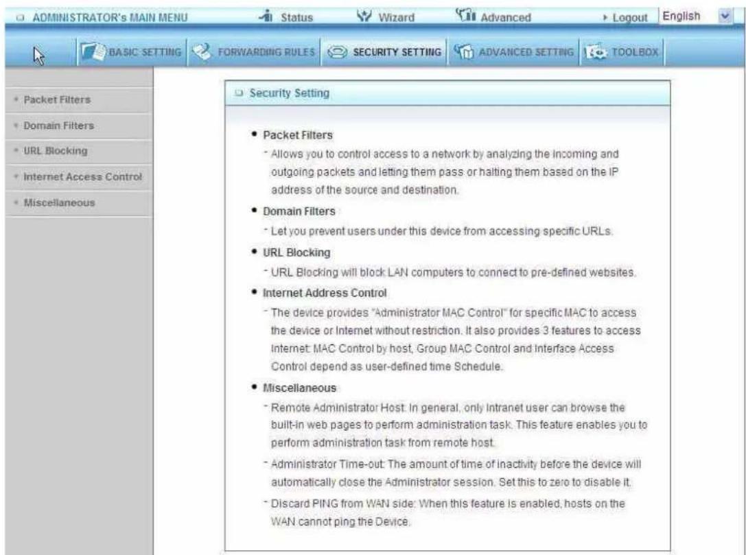
3.3.3.1 Packet Filters
![ADMINISTRATOR'S MAIN MENU Status Wizard Advanced Logout English BASIC SETTING FORWARDING RULES SECURITY SETTING ADVANCED SETTING TOOLBOX Outbound Packet Filter [HELP] Item Setting Outbound Filter Enable Allow all to pass except those match the following rules. Deny all to pass except those match the following rules. Block List -- select one -- Schedule rule (ID)Always Copy to ID -- ID Source IP Destination IP : Ports Enable Schedule Rule# 1 0 2 0 3 0 4 0 5 0 6 0 7 0 8 0 Save Undo Inbound Filter...](/content/2026/05/920108/images/cf30606d9950bb442aa4bf90d84c8457fcab7ad8e47faf3d43c80c00d27b2ef3.jpg)
Packet Filter enables you to control what packets are allowed to pass the router. Outbound filter applies on all outbound packets. However, Inbound filter applies on packets that destined to Virtual Servers or DMZ host only. You can select one of the two filtering policies:
Allow all to pass except those match the specified rules
Deny all to pass except those match the specified rules
You can specify 8 rules for each direction: inbound or outbound. For each rule, you can define the following:
Source IP address
Source port address
Destination IP address
Destination port address
Protocol: TCP or UDP or both.
Use Rule#
For source or destination IP address, you can define a single IP address (4.3.2.1) or a range of IP addresses (4.3.2.1-4.3.2.254). An empty implies all IP addresses.
For source or destination port, you can define a single port (80) or a range of ports (1000-1999). Add prefix "T" or "U" to specify TCP or UDP protocol. For example, T80, U53, U2000-2999. No prefix indicates both TCP and UDP are defined. An empty implies all port addresses. Packet Filter can work with Scheduling Rules, and give user more flexibility on Access control. For Detail, please refer to Scheduling Rule.
Each rule can be enabled or disabled individually.
Inbound Filter:
To enable Inbound Packet Filter click the check box next to Enable in the Inbound Packet Filter field.
Suppose you have SMTP Server (25), POP Server (110), Web Server (80), FTP Server (21), and News Server (119) defined in Virtual Server or DMZ Host.
Example 1:
![ADMINISTRATOR'S MAIN MENU Status Wizard Advanced Logout English BASIC SETTING FORWARDING RULES SECURITY SETTING ADVANCED SETTING TOOLIGN Packet Filters Domain Filters URL Blocking Internet Access Control Miscellaneous Outbound Packet Filter [HELP] Item Setting Outbound Filter Enable Allow all to pass except those match the following rules. Deny all to pass except those match the following rules. Block List -SELECT 006 - Schedule rule (00)Always Copy to ID - ID Source IP Destination IP : Ports Enable Schedule Rule# 1 1.2.3.100-1.2.3.149 25-100 0 2 1.2.3.10-1.2.3.20 0 0 3 0 0 4 0 0 5 0 0 6 0 0 7 0 0 8 0 0 Save Undo Inbound Filter...](/content/2026/05/920108/images/4ea05d0c57477e2caf0cdf646016d104d8d3ef468a2a4e3cdfb17d7d54a40b49.jpg)
(1.2.3.100-1.2.3.149) Remote hosts are allow to send mail (port 25), and browse the Internet (port 80)
(1.2.3.10-1.2.3.20) Remote hosts can do everything (block nothing)
Others are all blocked.
Example 2:
![ADMINISTRATOR's MAIN MENU Status Wizard Advanced Logout English BASIC SETTING FORWARDING RULES SECURITY SETTING ADVANCED SETTING TOOLBOX Packet Filters Domain Filters URL Blocking Internet Access Control Miscellaneous Outbound Packet Filter [HELP] Item Setting Outbound Filter Enable Allow all to pass except those match the following rules. Deny all to pass except those match the following rules. Block List -select one - Schedule rule (00)Always Copy to ID - ID Source IP Destination IP:Ports Enable Schedule Rule# 1 1.2.3.100-1.2.3.199 21 0 2 1.2.3.100-1.2.3.199 199 0 3 0 0 0 4 0 0 0 5 0 0 0 6 0 0 0 7 0 0 0 8 0 0 0 Save Undo Inbound Filter_](/content/2026/05/920108/images/f1e04e1bdf464b4d4827c58702dffd5273f0832c8c0efdb8ac01e0705597f1df.jpg)
(1.2.3.100-1.2.3.119) Remote hosts can do everything except read net news (port 119) and transfer files via FTP (port 21) behind Router Server.
Others are all allowed.
After Inbound Packet Filter setting is configured, click the save button.
Outbound Filter:
To enable Outbound Packet Filter click the check box next to Enable in the Outbound Packet Filter field.
Example 1:
Router LAN IP is 192.168.12.254
![ADMINISTRATOR'S MAIN MENU Status Wizard Advanced Logout English BASIC SETTING FORWARDING RULES SECURITY SETTING ADVANCED SETTING TOOLBOX Packet Filters Domain Filters URL Blocking Internet Access Control Miscellaneous Outbound Packet Filter [HELP] Item Setting Outbound Filter Enable Allow all to pass except those match the following rules. Deny all to pass except those match the following rules. Block List -- select one -- Schedule rule (00)Always Copy to ID -- ID Source IP Destination IP:Ports Enable Schedule Rule# 1 100-192.168.12.149 21-100 0 2 2.10-192.168.12.20 0 0 3 0 0 0 4 0 0 0 5 0 0 0 6 0 0 0 7 0 0 0 8 0 0 0 Save Undo Inbound Filter...](/content/2026/05/920108/images/63bcb65c17888558adf2387528a691dad021f088eb21b5919540f5fcc01e12b6.jpg)
(192.168.12.100-192.168.12.149) Located hosts are only allowed to send mail (port 25), receive mail (port 110), and browse Internet (port 80); port 53 (DNS) is necessary to resolve the domain name.
(192.168.12.10-192.168.12.20) Located hosts can do everything (block nothing) Others are all blocked.
Example 2:
Router LAN IP is 192.168.12.254
![ADMINISTRATOR'S MAIN MENU Status Wizard Advanced Logout English BASIC SETTING FORWARDING RULES SECURITY SETTING ADVANCED SETTING TOOLBOX Packet Filters Domain Filters URL Blocking Internet Access Control Miscellaneous Outbound Packet Filter [HELP] Item Setting Outbound Filter Enable Allow all to pass except those match the following rules. Deny all to pass except those match the following rules. Block List -- select one -- Schedule rule (00)Always Copy to ID -- ID Source IP Destination IP : Ports Enable Schedule Rule# 1 192.168.12.100 21 0 2 192.168.12.199 119 0 3 4 5 6 7 8 Save Undo Inbound Filter...](/content/2026/05/920108/images/b7d5c4f1c5176c8e9accd376b3511869187ad9c58ca16e8de381b59f25f1fd12.jpg)
(192.168.12.100 and 192.168.12.119) Located Hosts can do everything except read net news (port 119) and transfer files via FTP (port 21)
Others are allowed
After Outbound Packet Filter setting is configured, click the save button.
3.3.3.2 Domain filters
![ADMINISTRATOR'S MAIN MENU Status Wizard Advanced Logout English BASIC SETTING FORWARDING RULES SECURITY SETTING ADVANCED SETTING TOOL BOX Packet Filters Domain Filters URL Blocking Internet Access Control Miscellaneous Domain Filter [HELP] Item Setting Domain Filter Enable Log DNS Query Enable Privilege IP Addresses Range From 1 To 10 ID Domain Suffix Action Enable Schedule Rule# 1 www.vjc.com Drop Log 0 2 3 4 5 6 7 8 9 10 +(all others) Drop Log - 0 Save Undo](/content/2026/05/920108/images/f6d6ccfa06ce78baa98f8c1ef53bb2b351c690a7330a76f903224aa06981fbc4.jpg)
Domain Filter
Let you prevent users under this device from accessing specific URLs.
Domain Filter Enable
Check if you want to enable Domain Filter.
Log DNS Query
Check if you want to log the action when someone accesses the specific URLs.
Privilege IP Addresses Range
Setting a group of hosts and privilege these hosts to access network without restriction.
Domain Suffix
A suffix of URL to be restricted. For example, ".com", "xxx.com".
Action
When someone is accessing the URL met the domain-suffix, what kind of action you want.
Check drop to block the access. Check log to log these access.
Enable
Check to enable each rule.
Example:
![ADMINISTRATOR's MAIN MENU Status Wizard Advanced Logout English BASIC SETTING FORWARDING RULES SECURITY SETTING ADVANCED SETTING TOOLBOX Packet Filters Domain Filters URL Blocking Internet Access Control Miscellaneous Domain Filter [HELP] Item Setting Domain Filter Enable Log DNS Query Enable Privilege IP Addresses Range From 100 To 199 ID Domain Suffix Action Enable Schedule Rule# 1 www.msn.com Drop Log 0 2 www.sina.com Drop Log 0 3 www.baidu.com Drop Log 0 4 5 6 7 8 9 10 *(all others) Drop Log 0 Save Undo](/content/2026/05/920108/images/6997da21a4c48efc65540a9594a4454a9842060f79e9fce2dd7d592d8b9227cd.jpg)
In this example:
URL include "www.msn.com" will be blocked, and the action will be record in log-file. URL include "www.sina.com" will not be blocked, but the action will be record in log-file. URL include "www.baidu.com" will be blocked, but the action will not be record in log-file. IP address x.x.x.1\~x.x.x.99 can access Internet without restriction.
3.3.3.3 URL Blocking
![ADMINISTRATOR'S MAIN MENU Status Wizard Advanced Logout English BASIC SETTING FORWARDING RULES SECURITY SETTING ADVANCED SETTING TOOLBOX Packet Filters Domain Filters URL Blocking Internet Access Control Miscellaneous URL Blocking [HELP] Item Setting URL Blocking Enable ID URL Enable Schedule Rule# 1 2 3 4 5 6 7 8 9 10 Save Undo](/content/2026/05/920108/images/beb15b001cebc6298a71112a7e9013f82aaa66b6dffba3ff8f99ab9ef1d835a6.jpg)
URL Blocking will block LAN computers to connect to pre-defined Websites.
The major difference between “Domain filter” and “URL Blocking” is Domain filter require user to input suffix (like .com or .org, etc), while URL Blocking require user to input a keyword only. In other words, Domain filter can block specific website, while URL Blocking can block hundreds of websites by simply a keyword.
URL Blocking Enable
Checked if you want to enable URL Blocking.
URL
If any part of the Website's URL matches the pre-defined word, the connection will be blocked.
For example, you can use pre-defined word "sex" to block all websites if their URLs contain pre-defined word "sex".
Enable
Checked to enable each rule.
![ADMINISTRATOR'S MAIN MENU Status Wizard Advanced Logout English BASIC SETTING FORWARDING RULES SECURITY SETTING ADVANCED SETTING TOOLBOX URL Blocking [HFLP] Item Setting URL Blocking Enable ID URL Enable Schedule Rule# 1 msn 0 2 sina 0 3 4 5 6 7 8 9 10 Save Undo](/content/2026/05/920108/images/46dfad2cf919ed9476bdd6fb5a83c292b375ddc4068056f3dd70a7059af7c1f9.jpg)
In this example:
- URL include "msn" will be blocked, and the action will be record in log-file.
- URL include "sina" will be blocked, but the action will be record in log-file
3.3.3.4 Internet Access Control
The device provides "Administrator MAC Control" for specific MAC to access the device or Internet without restriction. It also provides 3 features to access Internet: MAC Control by host, Group MAC Control and Interface Access Control depend as user-defined time Schedule.
Administrator MAC Control
Regardless the MAC access configuration of administrator, specific MAC can access the device.
![ADMINISTRATOR'S MAIN MENU Status Wizard Advanced Logout English BASIC SETTING FORWARDING RULES SECURITY SETTING ADVANCED SETTING TOOLBOX Administrator MAC Control [HELP] DHCP clients 00-16-D4-EB-06-FC 182.158.123.151 (arrive nb) Copy to ID 1 ID MAC Address Enable 1 00-16-D4-EB-06-FC ✓ 2 3 Save Undo](/content/2026/05/920108/images/2738cfb77e541095dbfa4af674012a8d6b79f25306223b1d4de676a568c692f3.jpg)
This device can record 3 sets. When the host(should be admin) logins Web management, the device will record MAC address of this host. Before this host configures Internet Access Control, Suggest end-user to enable this feature, first.
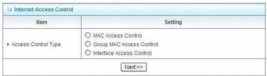
MAC control
![ADMINISTRATOR'S MAIN MENU Status Wizard Advanced Logout English BASIC SETTING FORWARDING RULES SECURITY SETTING ADVANCED SETTING TOOLBOX MAC Address Control [HELP] Item Setting MAC Address Control Enable Connection control Wireless and wired clients with C checked can connect to this device; and allow unspecified MAC addresses to connect. Association control Wireless clients with A checked can associate to the wireless LAN; and deny unspecified MAC addresses to associate. Note: Association control has no effect on wired clients. DHCP clients --- Select one --- Schedule rule (00)Always Copy to ID -- ID MAC Address IP Address C A Schedule Rule# 1 192.168.1 0 2 192.168.1 0 3 192.168.1 0 4 192.168.1 0 << Previous Next >> Save Undo](/content/2026/05/920108/images/2832df5eb135234e5ed333cdf041ffc972062ae85b08c0ce0ad862690768ac54.jpg)
MAC Address Control allows you to assign different access right for different users and to assign a specific IP address to a certain MAC address.
MAC Address Control Check "Enable" to enable the "MAC Address Control". All of the settings in this page will take effect only when "Enable" is checked.
Connection control Check "Connection control" to enable the controlling of which wired and wireless clients can connect to this device. If a client is denied to connect to this device, it means the client can't access to the Internet either. Choose "allow" or "deny" to allow or
AirLive GW-300R User's Manual
deny the clients, whose MAC addresses are not in the "Control table" (please see below), to connect to this device.
Association control Check "Association control" to enable the controlling of which wireless client can associate to the wireless LAN. If a client is denied to associate to the wireless LAN, it means the client can't send or receive any data via this device. Choose "allow" or "deny" to allow or deny the clients, whose MAC addresses are not in the "Control table", to associate to the wireless LAN.
Control table
| ID | MAC Address | IP Address | C | A | Schedule Rule# |
| 1 | 192.168.1. | 0 | |||
| 2 | 192.168.1. | 0 | |||
| 3 | 192.168.1. | 0 | |||
| 4 | 192.168.1. | 0 |
"Control table" is the table at the bottom of the "MAC Address Control" page. Each row of this table indicates the MAC address and the expected IP address mapping of a client. There are four columns in this table:
| MAC Address MAC address indicates a specific client. |
| IP Address Expected IP address of the corresponding client. Keep it empty if you don't care its IP address. |
| C When "Connection control" is checked, check "C" will allow the corresponding client to connect to this device. |
| A When "Association control" is checked, check "A" will allow the corresponding client to associate to the wireless LAN. |
In this page, we provide the following Combobox and button to help you to input the MAC address.

You can select a specific client in the "DHCP clients" Combobox, and then click on the "Copy to" button to copy the MAC address of the client you select to the ID selected in the "ID" Combobox.
Previous page and Next Page To make this setup page simple and clear, we have divided the "Control table" indogate to differentYou can use these buttons to nav pages.
Example:
![ADMINISTRATOR's MAIN MENU Status Wizard Advanced Logout English BASIC SETTING FORWARDING RULES SECURITY SETTING ADVANCED SETTING TOOLBOX Packet Filters Domain Filters URL Blocking Internet Access Control Miscellaneous MAC Address Control [HELP] Item Setting MAC Address Control Enable Connection control Wireless and wired clients with C checked can connect to this device; and allow unspecified MAC addresses to connect Association control Wireless clients with A checked can associate to the wireless LAN; and deny unspecified MAC addresses to associate. Note: Association control has no effect on wired clients. DHCP clients --- Select one --- Schedule rule (00)Always Copy to ID -- ID MAC Address IP Address C A Schedule Rule# 1 00-12-34-56-78-90 192.168.1.100 □ ✓ 0 2 192.168.1. ✓ ✓ 0 3 00-98-76-54-32-10 192.168.1.101 ✓ □ 0 4 192.168.1. □ □ 0 << Previous Next >> Save Undo](/content/2026/05/920108/images/4130e75d3a784b1cfb3441c2efbf36ebcede4bf20b2121672cd40daba4cffaeb.jpg)
In this scenario, there are three clients listed in the Control Table. Clients 1 and 2 are wireless, and client 3 is wired.
.The "MAC Address Control" function is enabled. 1
- "Connection control" is enabled, and all of the wired and wireless clients not listed in the "Control table" are "allowed" to connect to this device.
AirLive GW-300R User's Manual
3."Association control" is enabled, and all of the wireless clients not listed in the "Control table" are "denied" to associate to the wireless LAN.
- Clients 1 and 3 have fixed IP addresses either from the DHCP server of this device or manually assigned:
ID 1 - "00-12-34-56-78-90" --> 192.168.1.100
ID 3 - "00-98-76-54-32-10" --> 192.168.1.101
Client 2 will obtain its IP address from the IP Address pool specified in the "DHCP Server" page or can use a manually assigned static IP address.
If, for example, client 3 tries to use an IP address different from the address listed in the Control
table (192.168.12.101), it will be denied to connect to this device.
-
Clients 2 and 3 and other wired clients with a MAC address unspecified in the Control table are all allowed to connect to this device. But client 1 is denied to connect to this device.
-
Clients 1 and 2 are allowed to associate to the wireless LAN, but a wireless client with a MAC address not specified in the Control table is denied to associate to the wireless LAN. Client 3 is a wired client and so is not affected by Association control.
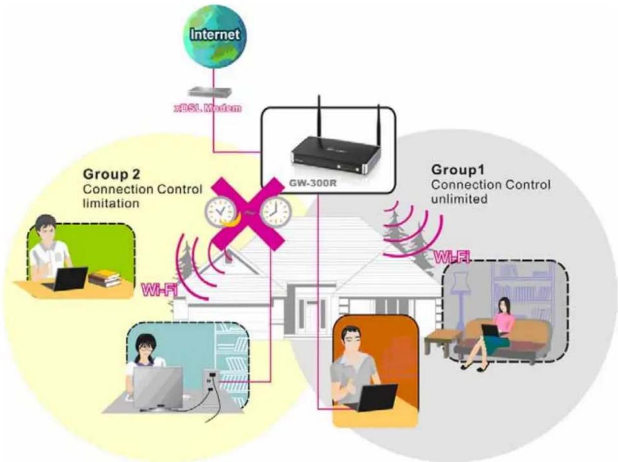
Group MAC Access Control
Administrator can define hosts in which Group to allow Internet. For example, Father and Mother are in Group1 without limitation and hosts Brother and Sister are in Group2 to access according as Schedule Rule2.
For example,
Schedule Rule 1 sets "always" everyday with limitation.
![ADMINISTRATOR's MAIN MENU Status Wizard Advanced Logout English BASIC SETTING FORWARDING RULES SECURITY SETTING ADVANCED SETTING TOOLBOX Packet Filters Domain Filters URL Blocking Internet Access Control Miscellaneous Group MAC Access Control [HELP] Item Setting Group MAC Access Control Enable Save Undo Add Member to Group List Add MAC Address - << Copy --- Select one --- to Group 1 and apply schedule rule (00)Always Add Add MAC : 00-16-D4-EB-06-FC to Group 1! Group List 1 - Always active. MAC Address Host Name IP Address Action 00-16-D4-EB-06-FC airlive-WayneNB 192.168.1.199 Delete](/content/2026/05/920108/images/938867fb71fc18446e2bd4510809dc07f37d4721e7d712a8a2f164fd92060973.jpg)
flowchart
graph TD
    A["Internet"] --> B["xDSL Modem"]
    B --> C["GW-300R"]
    C --> D["Group1 Connection Control unlimited"]
    D --> E["Wi-Fi"]
    D --> F["Wi-Fi"]
    D --> G["Wi-Fi"]
    D --> H["Wi-Fi"]
    I["Group 2 Connection Control limitation"] --> J["Wi-Fi"]
    J --> K["Network"]
    K --> L["Network"]
    L --> M["Network"]
    M --> N["Network"]
    style I fill:#f9f,stroke:#333
    style N fill:#bbf,stroke:#333
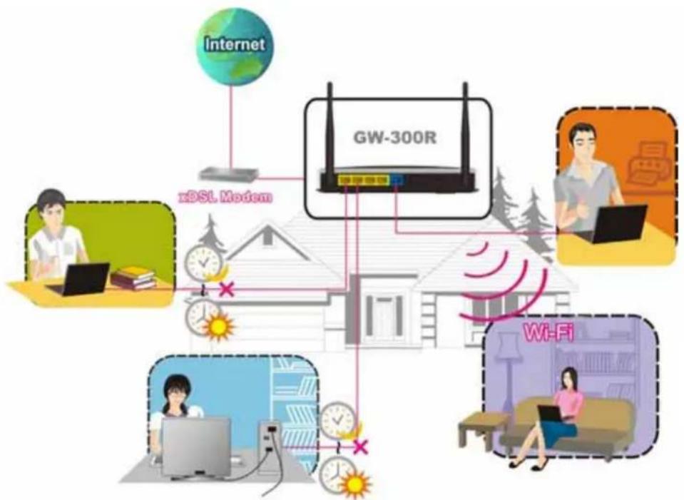
Interface Access Control
The device defines 5 Interfaces as Lan1,Lan2, Lan3,Lan4 and WiFi. The device allows different interface to access Internet by time schedule
For example, Schedule Rule 1 sets "always" everyday with limitation.
Schedule Rule 2 sets 08:00\~23:00 Monday \~ Friday.
Administrator can set guests in Lan3 and Lan4 to access Internet according as Schedule Rule
- Set Friends in Lan1, Lan2 and WiFi according as Schedule Rule 1.
![ADMINISTRATOR'S MAIN MENU Status Wizard Advanced Logout English BASIC SETTING FORWARDING ITEMS SECURITY SETTING ADVANCED SETTING TOOLBOX Packet Filters Domain Filters URL Blocking Internet Access Control Miscellaneous Interface Access Control [HELP] Item Setting Interface Access Control Enable Interface Schedule Rule Demy Port 1 (00)Always ✓ ✓ Port 2 (00)Always ✓ ✓ Port 3 (00)Always ✓ ✓ Port 4 (00)Always ✓ ✓ Wireless (00)Always ✓ ✓ Save Undo](/content/2026/05/920108/images/daa7fcc24d7afabaccffbc9d159fb0d8b671bf5472d34d705bd53da67b9bc79a.jpg)
flowchart
graph TD
    A["Internet"] --> B["xDSL Modem"]
    B --> C["GW-300R"]
    C --> D["Wi-Fi"]
    D --> E["Internet"]
    D --> F["Internet"]
    D --> G["Internet"]
    D --> H["Internet"]
    D --> I["Internet"]
    D --> J["Internet"]
    style A fill:#f9f,stroke:#333
    style B fill:#ccf,stroke:#333
    style C fill:#cff,stroke:#333
    style D fill:#ffc,stroke:#333
    style E fill:#cfc,stroke:#333
    style F fill:#fcc,stroke:#333
    style G fill:#fcf,stroke:#333
    style H fill:#cff,stroke:#333
    style I fill:#cfc,stroke:#333
    style J fill:#fcc,stroke:#333
3.3.3.5 Miscellaneous Items
![ADMINISTRATOR'S MAIN MENU Status Wizard Advanced Logout English BASIC SETTING FORWARDING RULES SECURITY SETTING ADVANCED SETTING TOOLBOX Packet Filters Domain Filters URL Blocking Internet Access Control Miscellaneous Miscellaneous Items [HELP] Item Setting Enable ► Remote Administrator Host / Port 0.0.0.0 / 88 ► Administrator Time-out 600 seconds (0 to disable) ► Discard PING from WAN side ► SPI mode ► DoS Attack Detection ► VPN PPTP Pass-Through ► VPN IPSec Pass-Through Save Undo](/content/2026/05/920108/images/889b303fc0e7e7b86d83796b906a9f966eb0a37c60ad40aed2cba2e3cbf68365.jpg)
Remote Administrator Host/Port
In general, only Intranet user can browse the built-in web pages to perform administration task. This feature enables you to perform administration task from remote host. If this feature is enabled, only the specified IP address can perform remote administration. If the specified IP address is 0.0.0.0, any host can connect to this product to perform administration task. You can use subnet mask bits "/nn" notation to specified a group of trusted IP addresses. For example, "10.1.2.0/24".
NOTE: When Remote Administration is enabled, the web server port will be shifted to 88. You can change web server port to other port, too.
Administrator Time-out
The time of no activity to logout automatically. Set it to zero to disable this feature.
Discard PING from WAN side
When this feature is enabled, any host on the WAN cannot ping this product.
SPI Mode
When this feature is enabled, the router will record the packet information pass through the router like IP address, port address, ACK, SEQ number and so on. And the router will check every incoming packet to detect if this packet is valid.
DoS Attack Detection
When this feature is enabled, the router will detect and log the DoS attack comes from the Internet. Currently, the router can detect the following DoS attack: SYN Attack, WinNuke, Port Scan, Ping of Death, Land Attack etc.
VPN IPSec Pass-Through
It is a setting/feature on routers which is required to implement secure exchange of packets at
the IP layer and allow IPSec tunnels to pass through the router.
VPN PPTP Pass-Through
It is a setting/feature on routers which is required in order to connect to a Remote PPTP VPN account.
3.3.4 Advanced Settings
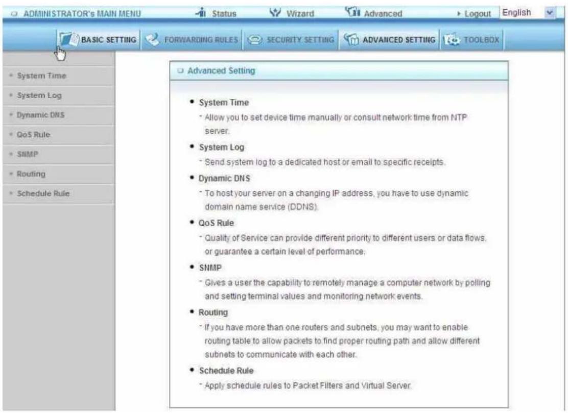
3.3.4.1 System Time
![ADMINISTRATOR's MAIN MENU Status Wizard Advanced Logout English BASIC SETTING FORWARDING RULES SECURITY SETTING ADVANCED SETTING TOOLBOX System Time [HELP] Item Setting ► System Time Friday, December 17, 2010 5:28:18 PM ► Get Date and Time by NTP Protocol Sync Now! Time Server time.nist.gov Time Zone (GMT-08:00) Pacific Time (US & Canada) ► Set Date and Time using PC's Date and Time PC Date and Time Friday, December 17, 2010 5:28:19 PM ► Set Date and Time manually Date Year: 2009 Month: Jun Day: 01 Time Hour: 0 (0-23) Minute: 0 (0-59) Second: 0 (0-59) ► Daylight Saving Enable Disable Start Month: Jan Day: 01 Hour: 00 End Month: Jan Day: 01 Hour: 00 System Time is: Fri Dec 17 17:28:10 2010 Save Undo](/content/2026/05/920108/images/0f68c7de748172d2e0b65a5606764d18e450dfdff8cf76f4228ca703374b924e.jpg)
Get Date and Time by NTP Protocol
Selected if you want to Get Date and Time by NTP Protocol.
Time Server
Select a NTP time server to consult UTC time
Time Zone
Select a time zone where this device locates.
Set Date and Time manually
Selected if you want to Set Date and Time manually.
Set Date and Time manually
Selected if you want to Set Date and Time manually.
Function of Buttons
Sync Now: Synchronize system time with network time server
Daylight Saving:Set up where the location is.
3.3.4.2 System Log
![ADMINISTRATOR's MAIN MENU Status Wizard Advanced Logout English BASIC SETTING FORWARDING RULES SECURITY SETTING ADVANCED SETTING TOOLBOX System Log [HELP] Item Setting Enable IP Address of Syslog Server 192.168.1 E-mail Alert Send Mail Now SMTP Server IP/Port E-mail addresses E-mail Subject User name Password Log Type System Activity Debug Information Attacks Dropped Packets Notice View Log... Save Undo](/content/2026/05/920108/images/e96e694cd89096f1bfbe74d60e9e7c12e4e2c270e6f679edc94c8c14313f8457.jpg)
This page supports two methods to export system logs to specific destination by means of syslog(UDP) and SMTP(TCP). The items you have to setup including:
IP Address for Syslog
Host IP of destination where syslogs will be sent to.
Check Enable to enable this function.
E-mail Alert Enable
Check if you want to enable Email alert (send syslog via email).
SMTP Server IP and Port
Input the SMTP server IP and port, which are concatenated with '':. If you do not specify port number, the default value is 25.
For example, "mail.your_url.com" or "192.168.1.100:26".
Send E-mail alert to
The recipients who will receive these logs. You can assign more than 1 recipient, using ';' or ',' to separate these email addresses.
To host your server on a changing IP address, you have to use dynamic domain name service (DDNS).
So that anyone wishing to reach your host only needs to know the name of it. Dynamic DNS will map the name of your host to your current IP address, which changes each time you connect your Internet service provider.
Before you enable Dynamic DNS, you need to register an account on one of these Dynamic DNS servers that we list in provider field.
To enable Dynamic DNS click the check box next to Enable in the DDNS field.
Next you can enter the appropriate information about your Dynamic DNS Server.
You have to define:
Provider
Host Name
Username/E-mail
Password/Key
You will get this information when you register an account on a Dynamic DNS server.
3.3.4.4 SNMP
![ADMINISTRATOR's MAIN MENU Status Wizard Advanced Logout English BASIC SETTING FORWARDING RULES SECURITY SETTING ADVANCED SETTING TOOLBOX SNMP Setting [HELP] Item Setting Enable SNMP Local Remote Get Community public Set Community private IP 1 IP 2 IP 3 IP 4 SNMP Version V1 V2c Save Undo](/content/2026/05/920108/images/79aa4ecf931f00993ef2d3083657849f118a811df0a711e605ca06d5016df46f.jpg)
In brief, SNMP, the Simple Network Management Protocol, is a protocol designed to give a user the capability to remotely manage a computer network by polling and setting terminal values and monitoring network events.
Enable SNMP
You must check Local, Remote or both to enable SNMP function. If Local is checked, this device will response request from LAN. If Remote is checked, this device will response request from WAN.
Get Community
Setting the community of GetRequest your device will response.
Set Community
Setting the community of SetRequest your device will accept.
IP 1, IP 2, IP 3, IP 4
Input your SNMP Management PC's IP here. User has to configure to where this device should send SNMP Trap message.
SNMP Version
Please select proper SNMP Version that your SNMP Management software supports.
3.3.4.5 Routing
![ADMINISTRATOR's MAIN MENU Status Wizard Advanced Logout English BASIC SETTING FORWARDING RULES SECURITY SETTING ADVANCED SETTING TOOLBOX Routing Table [HELP] Item Setting Dynamic Routing Disable RIPv1 RIPv2 Static Routing Disable Enable ID Destination Subnet Mask Gateway Hop Enable 1 2 3 4 5 6 7 8 Save Undo](/content/2026/05/920108/images/48e390bf64906b7182e13bb7c8ece15441c87765597f4b04831b2bd4194811b2.jpg)
Routing Tables allow you to determine which physical interface address to use for outgoing IP data grams. If you have more than one routers and subnets, you will need to enable routing table to allow packets to find proper routing path and allow different subnets to communicate with each other.
Routing Table settings are settings used to setup the functions of static.
Dynamic Routing
Routing Information Protocol (RIP) will exchange information about destinations for computing routes throughout the network. Please select RIPv2 only if you have different subnet in your network.
Otherwise, please select RIPv1 if you need this protocol.
Static Routing: For static routing, you can specify up to 8 routing rules. You can enter the destination IP address, subnet mask, gateway, hop for each routing rule, and then enable or disable the rule by checking or unchecking the Enable checkbox.
Example:
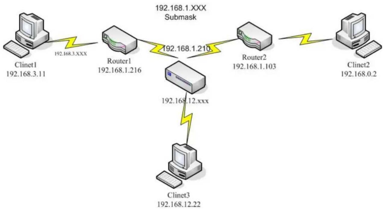
flowchart
graph TD
    A["Clinet1 192.168.3.11"] -->|192.168.3.XXX| B["Router1 192.168.1.216"]
    B -->|192.168.1.210| C["Router2 192.168.1.103"]
    C -->|192.168.1.XXX Submask| D["Clinet3 192.168.12.22"]
    D -->|192.168.12.XXX| B
    E["Clinet2 192.168.0.2"] -->|192.168.0.2| F["Computer"]
Configuration on NAT Router
| Destination | SubnetMask | Gateway | Hop | Enabled |
| 192.168.3.0 | 255.255.255.0 | 192.168.1.216 | 1 | |
| 192.168.0.0 | 255.255.255.0 | 192.168.1.103 | 1 |
So if, for example, the client3 wanted to send an IP data gram to 192.168.0.2, it would use the above table to determine that it had to go via 192.168.1.103 (a gateway),
And if it sends Packets to 192.168.3.11 will go via 192.168.1.216
Each rule can be enabled or disabled individually.
After routing table setting is configured, click the save button.
3.3.4.6 Schedule Rule
![ADMINISTRATOR's MAIN MENU Status Wizard Advanced Logout English BASIC SETTING FORWARDING RULES SECURITY SETTING ADVANCED SETTING TOOLBOX Schedule Rule [HELP] Item Setting Schedule Enable Rule# Rule Name Action Save Add New Rule...](/content/2026/05/920108/images/164e7ca35195d2e2a6a2eeec69e9d01156d6af48d50683f9c46c7cac63ac9d85.jpg)
You can set the schedule time to decide which service will be turned on or off. Select the "enable" item.
Press "Add New Rule"
You can write a rule name and set which day and what time to schedule from "Start Time" to "End Time". The following example configure "ftp time" as everyday 14:10 to 16:20
![ADMINISTRATOR'S MAIN MENU Status Wizard Advanced Logout English BASIC SETTING FORWARDING RULES SECURITY SETTING ADVANCED SETTING TOOLBOX Schedule Rule Setting [HELP] Item Setting Name of Rule 1 System Time Friday, December 17, 2010 5:38:56 PM Week Day Start Time (hh:mm) End Time (hh:mm) Sunday : : Monday : : Tuesday : : Wednesday : : Thursday : : Friday : : Saturday : : Every Day : : Save Undo Back](/content/2026/05/920108/images/3d2ed1ce1043a4d0dfca4d87915a96a345f37d26bdd532e9679610b0d14489f1.jpg)
Schedule Enable
Selected if you want to Enable the Scheduler.
Edit
To edit the schedule rule.
Delete
To delete the schedule rule, and the rule# of the rules behind the deleted one will decrease one automatically.
Schedule Rule can be apply to Virtual server and Packet Filter, for example:
Example1: Virtual Server – Apply Rule#1 (ftp time: everyday 14:20 to 16:30)
![ADMINISTRATOR's MAIN MENU Status Wizard Advanced Logout English BASIC SETTING FORWARDING RULES SECURITY SETTING ADVANCED SETTING TOOLBOX Virtual Server [ HELP ] Well known services -- select one -- Schedule rule (00)Always Copy to ID -- ID Server IP Service Ports Protocol Enable Schedule Rule# 1 192.168.1.1 21 Both ✓ 1 2 192.168.1. Both ✓ 0 3 192.168.1. Both ✓ 0 4 192.168.1. Both ✓ 0 5 192.168.1. Both ✓ 0 6 192.168.1. Both ✓ 0 7 192.168.1. Both ✓ 0 8 192.168.1. Both ✓ 0 9 192.168.1. Both ✓ 0 10 192.168.1. Both ✓ 0 Next >> Save Undo](/content/2026/05/920108/images/e8db9be8aa727bf4958fce52a98e8005209fbe5bb800e5ac24589eda6d9d5d79.jpg)
Example2: Packet Filter – Apply Rule#1 (ftp time: everyday 14:20 to 16:30).
![ADMINISTRATOR's MAIN MENU Status Wizard Advanced Logout English BASIC: SETTING FORWARDING RULES SECURITY SETTING ADVANCED SETTING TOOLBOX Packet Filters Domain Filters URL Blocking Internet Access Control Miscellaneous Outbound Packet Filter [HELP] Item Setting Outbound Filter Enable Allow all to pass except those match the following rules. Deny all to pass except those match the following rules. Block List -- select one -- Schedule rule (00)Always Copy to ID -- ID Source IP Destination IP : Ports Enable Schedule Rule# 1 21 1 2 0 3 0 4 0 5 0 6 0 7 0 8 0 Save Undo Inbound Filter...](/content/2026/05/920108/images/c5b7978668de9252d1600b072ccbedd979a0095073bc52819bfaa6bbccda3273.jpg)
3.3.4.7 QoS Rule
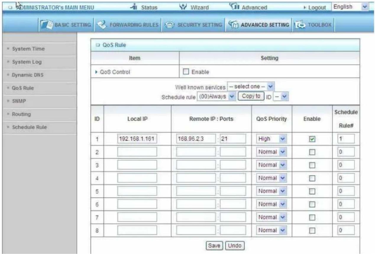
Local IP:
Please input Client IP, ex192.168.1.161.
Remote Priority:
Please input Global IP and port, ex:168.96.2.3 and port 21
3.3.5 Toolbox
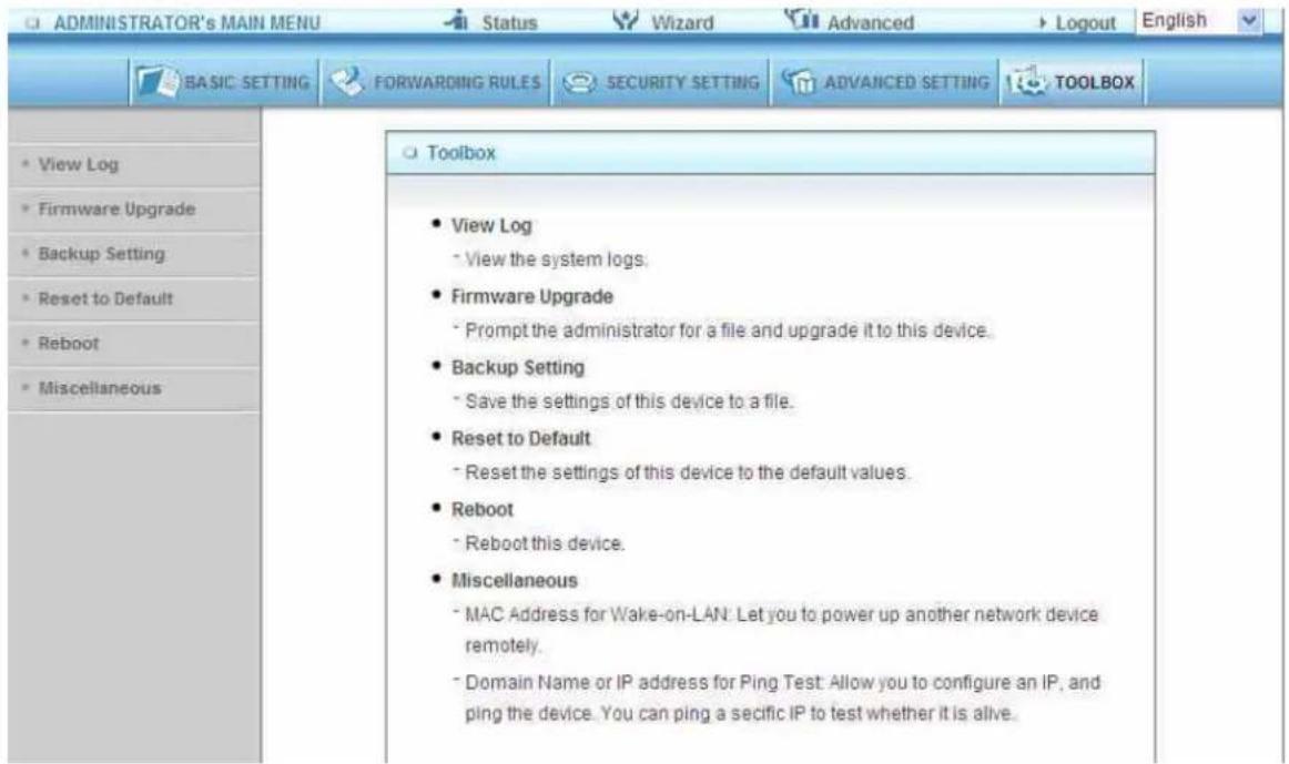
3.3.5.1 View Log
| System Log | |
| Item | Info |
| WAN Type | Static IP Address (R0.29g0) |
| Display time | Fri Dec 17 17:44:29 2010 |
| Time | Log |
| Friday, December 17, 2010 2:38:37 PM | Blocked access attempt from 192.168.0.10:2300 to UDP port 19287 |
| Friday, December 17, 2010 2:40:36 PM | Admin from 192.168.1.160 login successfully |
| Friday, December 17, 2010 2:48:31 PM | Admin from 192.168.1.161 login successfully |
| Friday, December 17, 2010 2:50:06 PM | Restarted by 192.168.1.161 |
| Friday, December 17, 2010 2:50:50 PM | User from 192.168.123.161 login failed |
| Friday, December 17, 2010 2:50:54 PM | Admin from 192.168.123.161 login successfully |
| Friday, December 17, 2010 2:51:22 PM | Associated: 00-12-0E-9A-B2-15 st=0 |
| Friday, December 17, 2010 2:55:42 PM | Disassociated: 00-12-0E-9A-B2-15 wcid=1 |
| Friday, December 17, 2010 2:56:12 PM | Admin from 192.168.123.161 logged out |
| Friday, December 17, 2010 2:57:41 PM | User from 192.168.123.161 login failed |
| Friday, December 17, 2010 2:57:45 PM | Admin from 192.168.123.161 login successfully |
| Friday, December 17, 2010 3:14:23 PM | Restarted by 192.168.123.161 |
| Friday, December 17, 2010 3:14:25 PM | DOD: 192.168.123.161 query DNS for messenger.hotmail.com |
| Friday, December 17, 2010 3:14:25 PM | DHCP:discover(My Host) |
| Friday, December 17, 2010 3:14:25 PM | DHCP:offer(192.168.1.234) |
You can View system log by clicking the View Log button
3.3.5.2 Firmware Upgrade
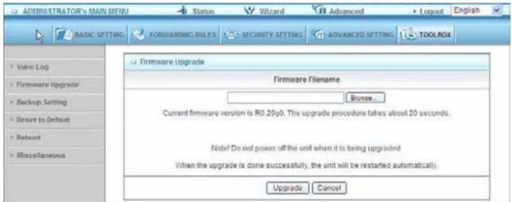
You can upgrade firmware by clicking Firmware Upgrade button.
3.3.5.3 Backup Setting
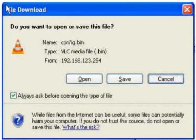
You can backup your settings by clicking the Backup Setting button and save it as a bin file. Once you want to restore these settings, please click Firmware Upgrade button and use the bin file you saved.
3.3.5.4 Reset to default
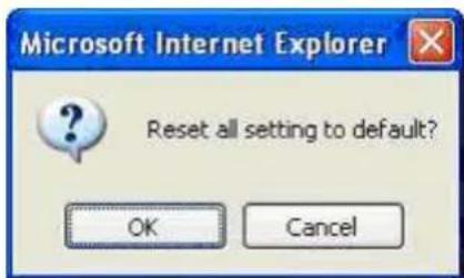
You can also reset this product to factory default by clicking the Reset to default button.
3.3.5.5 Reboot
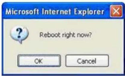
You can also reboot this product by clicking the Reboot button.
3.3.5.6 Miscellaneous Items
![ADMINISTRATOR's MAIN MENU Status Wizard Advanced Logout English BASIC SETTING FORWARDING RULES SECURITY SETTING ADVANCED SETTING TOOLBOX View Log Firmware Upgrade Backup Setting Reset to Default Reboot Miscellaneous Miscellaneous Items [HELP] Item Setting MAC Address for Wake-on-LAN Wake up Domain Name or IP address for Ping Test Ping Save Undo](/content/2026/05/920108/images/5966595b17a720f2253e05d6f436dd4e9b7d5500a3ccc31658ddddbd409d9835.jpg)
MAC Address for Wake-on-LAN
Wake-on-LAN is a technology that enables you to power up a networked device remotely. In order to enjoy this feature, the target device must be Wake-on-LAN enabled and you have to know the MAC address of this device, say 00-11-22-33-44-55. Clicking "Wake up" button will make the router to send the wake-up frame to the target device immediately.
Domain Name or IP Address for Test
Allow you to configure an IP, and ping the device. You can ping a secific IP to test whether it is alive.
Appendices and Index
802.1x Setting
1 Equipment Details
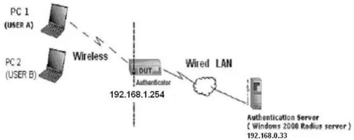
flowchart
graph LR
    A["PC 1 (USER A)"] -->|Wireless| B["DUT"]
    C["PC 2 (USER B)"] -->|Wireless| B
    B -->|Wired LAN| D["Authentication Server (Windows 2000 Radius server)"]
    B -->|192.168.1.254| E["192.168.0.33"]
Figure 1: Testing Environment (Use Windows 2000 Radius Server)
PC1:
Microsoft Windows XP Professional without Service Pack 1.
AirLive WN-200USB
Driver version:
PC2:
Microsoft Windows XP Professional with Service Pack 1a or latter.
AirLive WN-200USB
Driver version: 1.7.29.0 (Driver date: 10.20.2001)
Authentication Server: Windows 2000 RADIUS server with Service Pack 3 and HotFix Q313664.
Note. Windows 2000 RADIUS server only supports PEAP after upgrade to service pack 3 and
HotFix Q313664 (You can get more information from
HH http://support.microsoft.com/default.aspx?scid=kb; en-us;313664UH)
2 DUT
Configuration:
Enable DHCP server.
WAN setting: static IP address.
LAN IP address: 192.168.1.254/24.
Set RADIUS server IP.
Set RADIUS server shared key.
Configure WEP key and 802.1X setting.
The following test will use the inbuilt 802.1X authentication method such as ,EAP_TLS, PEAP_CHAPv2(Windows XP with SP1 only), and PEAP_TLS(Windows XP with SP1 only) using the Smart Card or other Certificate of the Windows XP Professional.
3. DUT and Windows 2000 Radius Server Setup
Setup Windows 2000 RADIUS Server
We have to change authentication method to MD5_Challenge or using smart card or other certificate on RADIUS server according to the test condition.
Setup DUT
Enable the 802.1X (check the "Enable checkbox").
Enter the RADIUS server IP.
Enter theshared key. (The key shared by the RADIUS server and DUT).
We will change 802.1X encryption key length to fit the variable test condition.
Setup Network adapter on PC
- Choose the IEEE802.1X as the authentication method. (Fig 2)
Note.
Figure 2 is a setting picture of Windows XP without service pack 1. If users upgrade to service pack 1, then they can't see MD5-Challenge from EAP type list any more, but they will get a new Protected EAP (PEAP) option.
Choose MD5-Challenge or Smart Card or other Certificate as the EAP type.
-
If choosing use smart card or the certificate as the EAP type, we select to use a certificate on this computer. (Fig 3)
-
We will change EAP type to fit the variable test condition.
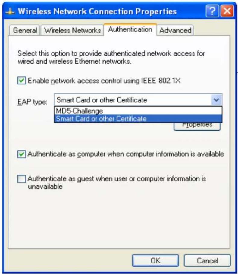
Figure 2: Enable IEEE 802.1X access control
Figure 3: Smart card or certificate properties
4. Windows 2000 RADIUS server Authentication testing:
4.1 DUT authenticate PC1 using certificate. (PC2 follows the same test procedures.)
Download and install the certificate on PC1. (Fig 4)
PC1 choose the SSID of DUT as the Access Point.
Set authentication type of wireless client and RADIUS server both toEAP_TLS.
Disable the wireless connection and enable again.
The DUT will send the user's certificate to the RADIUS server, and then send the message of authentication result to PC1. (Fig 5)
Windows XP will prompt that the authentication process is success or fail and end the authentication procedure. (Fig 6)
Terminate the test steps when PC1 get dynamic IP and PING remote host successfully.
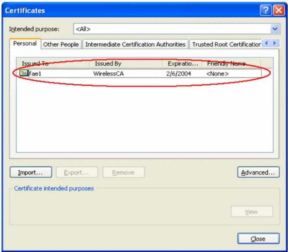
Figure 4: Certificate information on PC1
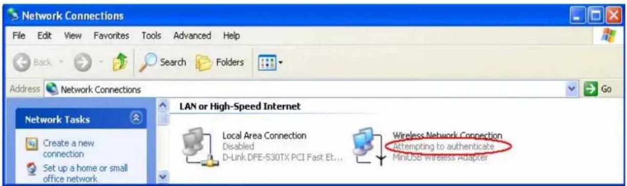
Figure 5: Authenticating
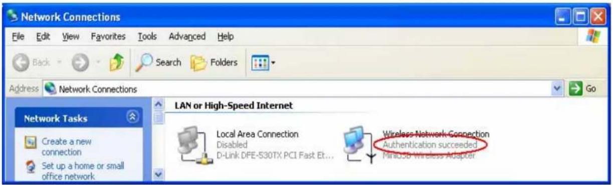
Figure 6: Authentication success
4.2 DUT authenticate PC2 using PEAP-TLS.
PC2 choose the SSID of DUT as the Access Point.
Set authentication type of wireless client and RADIUS server both to PEAP_TLS.
Disable the wireless connection and enable again.
The DUT will send the user's certificate to the RADIUS server, and then
send the message of authentication result to PC2.
Windows XP will prompt that the authentication process is success or fail and end the authentication procedure.
Terminate the test steps when PC2 get dynamic IP and PING remote host successfully.
Support Type: The router supports the types of 802.1x Authentication:
PEAP-CHAPv2 and PEAP-TLS.
Note.
PC1 is on Windows XP platform without Service Pack 1.
PC2 is on Windows XP platform with Service Pack 1a.
PEAP is supported on Windows XP with Service Pack 1 only.
Windows XP with Service Pack 1 allows 802.1x authentication only when data encryption function is enable.
WPA Settings
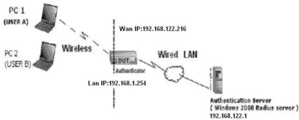
flowchart
graph TD
    A["PC 1 (USER A)"] -->|Wireless| B["DUT"]
    C["PC 2 (USER B)"] -->|Wireless| B
    B -->|Wired LAN| D["Authentication Server (Windows 2000 Radius server)"]
    B -->|Wan IP:192.168.122.216| E["LAN IP:192.168.1.254"]
Wireless Router: LAN IP: 192.168.1.254
WAN IP: 192.168.122.216
Radius Server: 192.168.122.1
UserA : XP Wireless Card:Ti-11g
Tool: Odyssey Client Manager
Refer to: HHUwww.funk.comUHH
Download: HHUhttp://www.funk.com/News&Events/ody_c_wpa_preview_pn.aspU
Or Another Configuration:
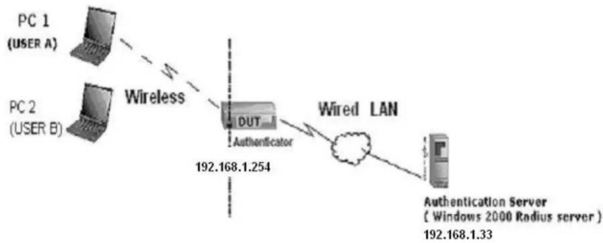
flowchart
graph LR
    PC1["PC 1 (USER A)"] -->|Wireless| DUT["DUT"]
    PC2["PC 2 (USER B)"] -->|Wireless| DUT
    DUT -->|Wired LAN| LAN["Authentication Server (Windows 2000 Radius server)"]
    LAN -->|192.168.1.33| LAN
    style DUT fill:#f9f,stroke:#333
    style LAN fill:#ccf,stroke:#333
WPA:
For this function, we need the server to authenticate. This function is like 802.1x.
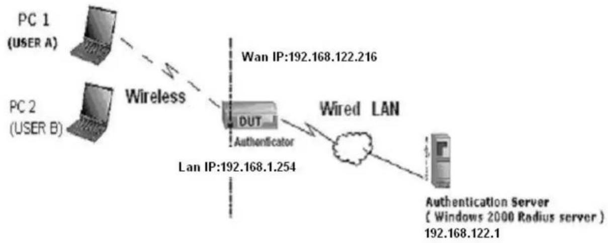
flowchart
graph TD
    PC1["PC 1 (USER A)"] -->|Wireless| DUT["DUT"]
    PC2["PC 2 (USER B)"] -->|Wireless| DUT
    DUT -->|Wired LAN| LAN["LAN IP:192.168.1.254"]
    LAN -->|Wan IP:192.168.122.216| Server["Authentication Server (Windows 2000 Radius server)"]
    Server -->|192.168.122.1| LAN
The above is our environment:
Method 1:
- The UserA or UserB have to get certificate from Radius, first.
HHUhttp://192.168.122.1/certsrvU
account : fae1
passwd : fae1
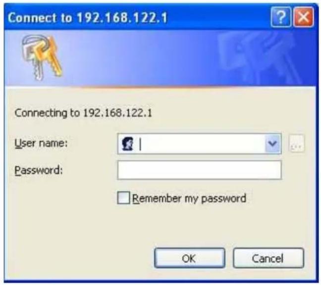
- Then, Install this certificate and finish.
- Go to the Web manager of Wireless Router to configure, like below:
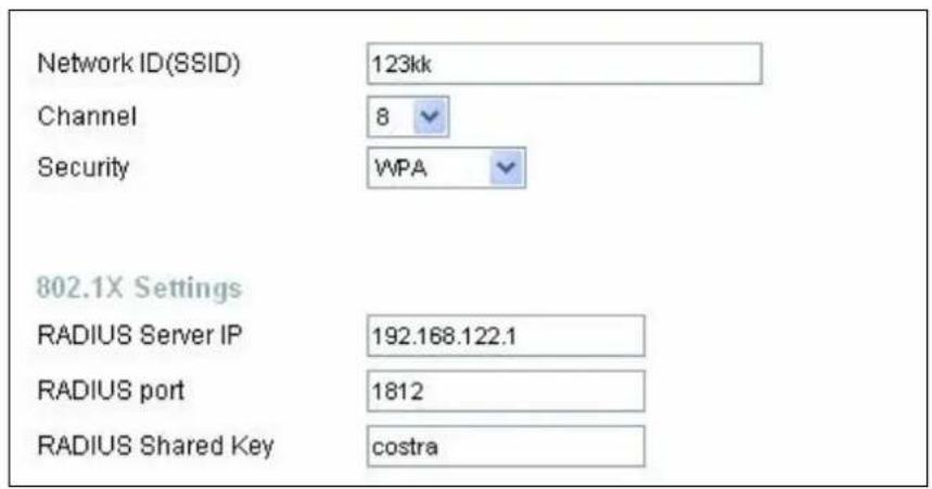
- Go to Odyssey Client Manager, choose "Profiles" and Setup Profile name as "1"
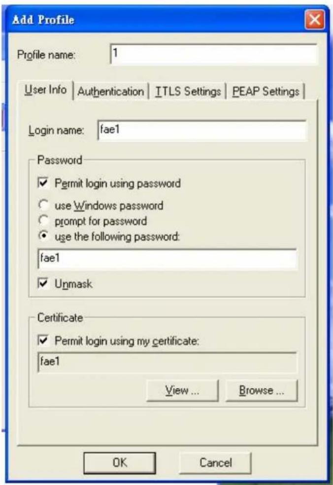
Login name and passwd are fae1 and fae1.
Remember that you get certificate from Radius in Step1.
- Then Choose "certificate" like above.
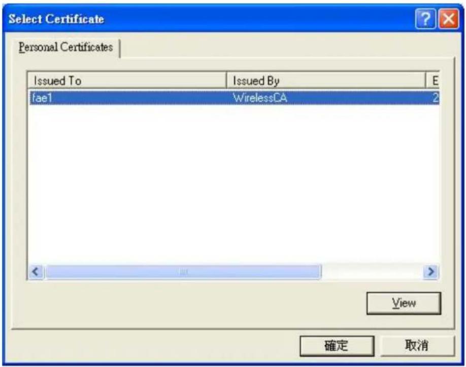
- Then go to Authentication and first Remove EAP/ TLS and Add EAP/TLS again.
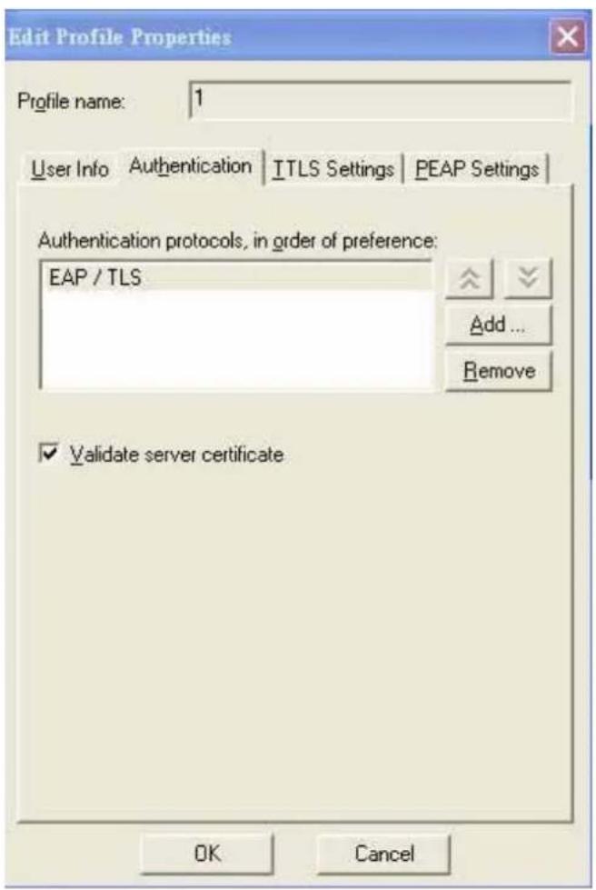
7. Go "Network" and Select "1" and ok
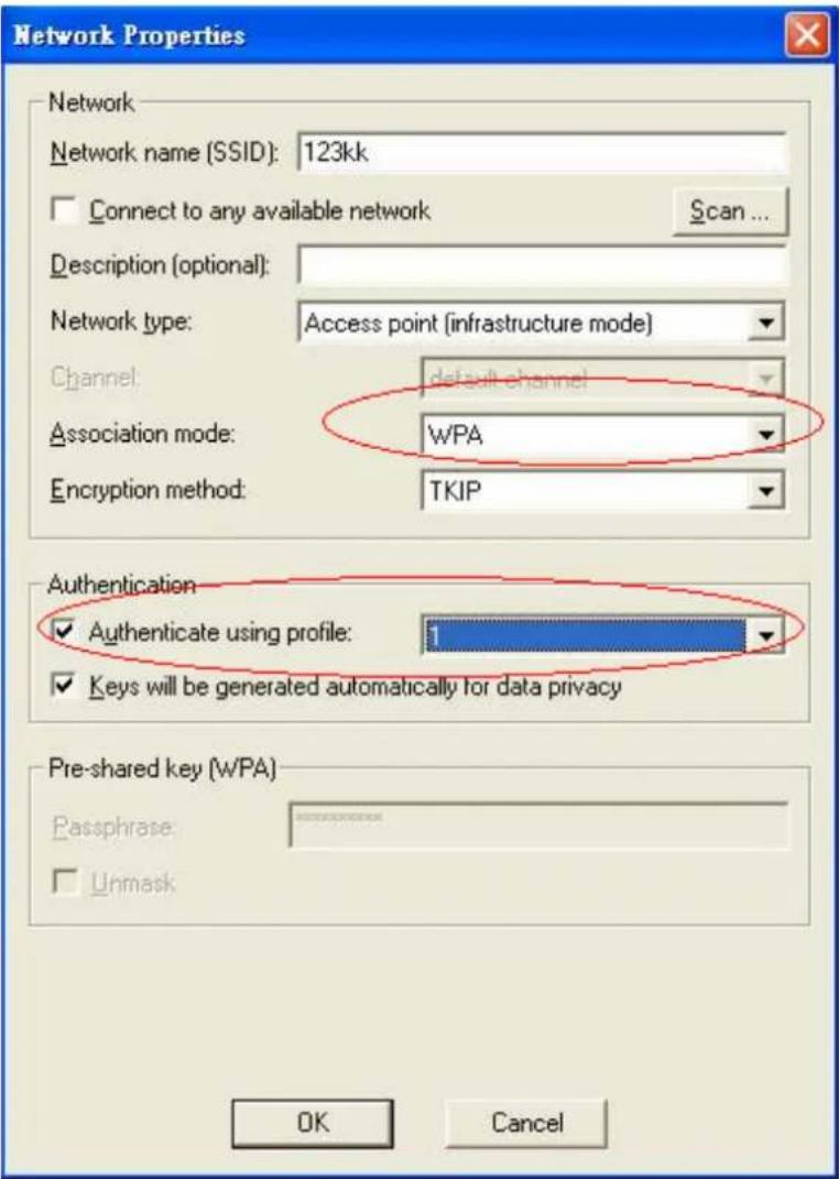
8. Back to Connection and Select "123kk.
If successfully, the wireless client has to authenticate with Radius Server, like below:
![Network Properties Network Network name (SSID): 123kk Connect to any available network Scan... Description (optional) Network type: Connection Profiles Networks Auto-Scan Lists Trusted Servers Adapters Odyoury Client You are about to authenticate to an untrusted server! To terminate communication, press [No] To temporarily trust this server, press [Yes] To permanently trust this server, check "add this trusted server to the database" and press [Yes] Certificate chain: WirelessCA win2000adv intra.com.tw View... Permanent trust Add this trusted server to the database Server name must end with: win2000adv intra.com.tw Proceed to authenticate with this server? Yes No](/content/2026/05/920108/images/40b2162ebada4cc00dd0b3b85f97674fbbf1f448dd21763f843ed9429e1c17c6.jpg)
9.Result:
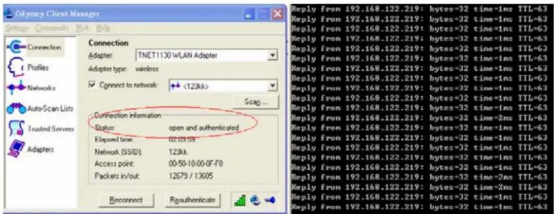
Method 2:
- The UserA or UserB have to get certificate from Radius, first. HHUhttp://192.168.122.1/certsrvU
account:fae1
passwd:fae1
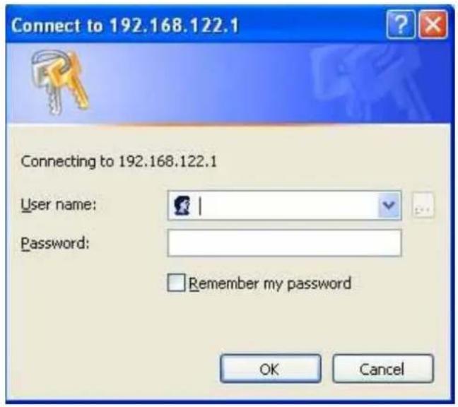
- Then Install this certificate and finish.
- Setting on the router and client:
Router:
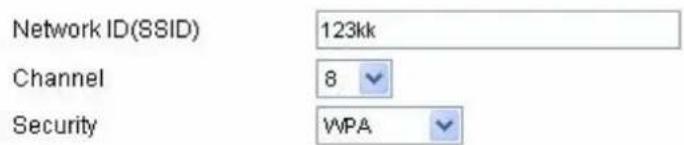
802.1X Settings
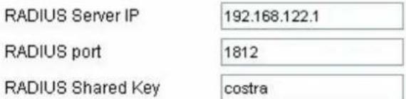
Client:
Go to "Network Connection" and select wireless adapter.
Choose "View available Wireless Networks" like below:
Advanced→ choose "123kk"
Select "WirelessCA and Enable" in Trusted root certificate authority:
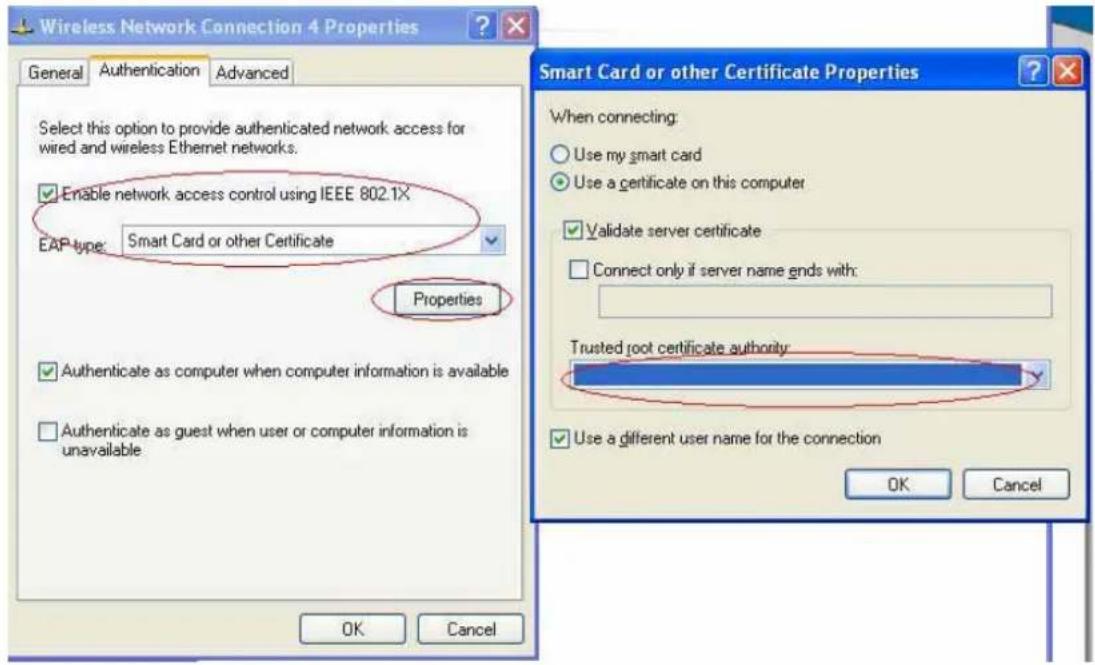
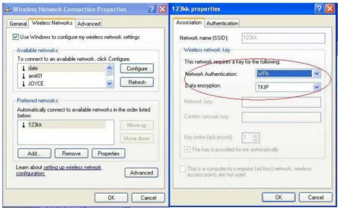
Then, if the wireless client wants to associate, it has to request to authenticate.
FAQ and Troubleshooting
What can I do when I have some trouble at the first time?
- Why can I not configure the router even if the cable is plugged in the ports of Router and the led is also light?
A: First, make sure that which port is plugged. If the cable is in the Wan port, please change to plug in Lan port 1 or Lan port 4:
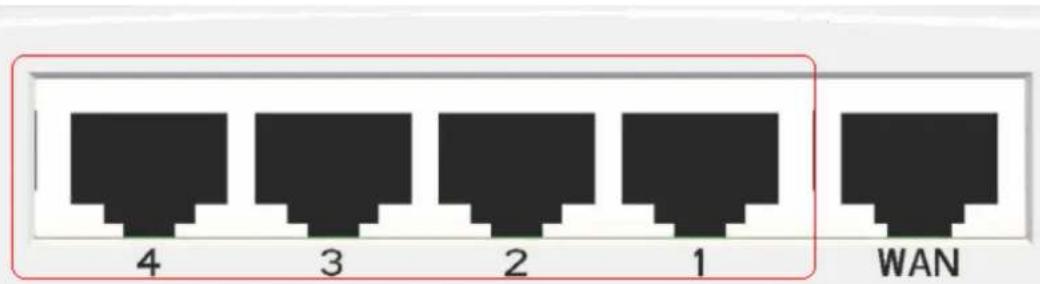
Then, please check if the Pc gets ip address from Router. Use command mode as below:
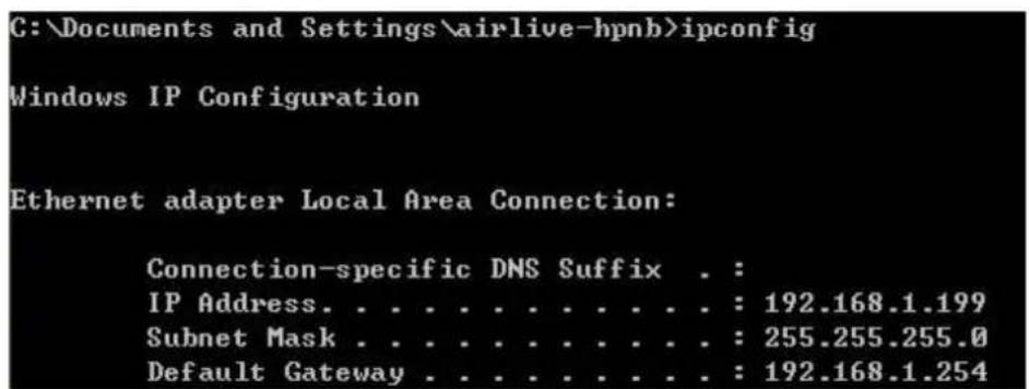
If yes, please execute Browser, like Mozilla and key 192.168.1.254 in address. If not, please ipconfig /release, then ipconfig /renew.
C:\>ipconfig /release
Windows IP Configuration

Ethernet adapter Local Area Connection:
    Connection-specific DNS Suffix . :
    IP Address. . . . . . . . . . . . . : 0.0.0.0
    Subnet Mask . . . . . . . . . . . . : 0.0.0.0
    Default Gateway . . . . . . . . . . :

C:\>ipconfig /renew
Windows IP Configuration

Ethernet adapter Local Area Connection:
    Connection-specific DNS Suffix . : 192.168.1.199
    IP Address. . . . . . . . . . . . : 255.255.255.0
    Subnet Mask . . . . . . . . . . : 192.168.1.254
    Default Gateway . . . . . . . . :
Whatever I setup, the pc can not get ip. Please check Status Led and refer to the Q2:
- Why can I not connect the router even if the cable is plugged in Lan port and the led is light?
A: First, please check Status Led. If the device is normal, the led will blink per second. If not, please check How blinking Status led shows.
There are many abnormal symptoms as below:
Status Led is bright or dark in work: The system hanged up .Suggest powering off and on the router. But this symptom often occurs, please reset to default or upgrade latest fw to try again.
Status led flashes irregularly: Maybe the root cause is Flash rom and please press reset Button to reset to default or try to use Recovery mode.(Refer to Q3 and Q4)
Status flashes very fast while powering on: Maybe the router is the recovery mode and please refer to Q4.
3.How to reset to factory default?
A: Press Wireless on /off and WPS button simultaneously about 5 sec Status will start flashing about 5 times, remove the finger. The RESTORE process is completed.
- Why can I not connect Internet even though the cables are plugged in Wan port and Lan port and the leds are blink. In addition, Status led is also normal and I can configure web management?
A: Make sure that the network cable from DSL or Cable modem is plugged in Wan port of Router and
that the network cable from Lan port of router is plugged in Ethernet adapter. Then, please check which wan type you use. If you are not sure, please call the isp. Then please go to this page to input the
information isp is assigned.
| ☐ Choose WAN Type | |
| Type | Usage |
| Static IP Address | ISP assigns you a static IP address. |
| Dynamic IP Address | Obtain an IP address from ISP automatically. |
| Dynamic IP Address with Road Runner Session Management.(e.g. Telstra BigPond) | |
| PPP over Ethernet | Some ISPs require the use of PPPoE to connect to their services. |
| PPTP | Some ISPs require the use of PPTP to connect to their services. |
| L2TP | Some ISPs require the use of L2TP to connect to their services. |
- When I use Static IP Address to roam Internet, I can access or ping global IP 202.93.91.218, But I can not access the site that inputs domain name, for example HHUhttp://espn.comUHH?
A: Please check the dns configuration of Static IP Address. Please refer to the information of ISP and assign one or two in dns item.
How do I connect router by using wireless?
1.How to start to use wireless?
A: First, make sure that you already installed wireless client device in your computer. Then check the Configuration of wireless router. The default is as below:
![Wireless Setting [ HELP ] Item Setting ► Wireless ○ Enable ○ Disable ► Network ID(SSID) default ► Wireless Mode ○ 11 b/g/n Mixed ○ 11n only ► SSID Broadcast ○ Enable ○ Disable ► Channel 11 ► Security None Save Undo WDS Setting... MAC Address Control... Wireless Client List...](/content/2026/05/920108/images/b1921cecc79187da807ba9dabc95596fac008e00b12b369610d287d11ce5b6b6.jpg)
bout wireless client, you will see wireless icon: A
natural_image
Minimalist graphic with a small icon and a double arrow symbol, no readable text or symbols present.Then click and will see the ap list that wireless client can be accessed:
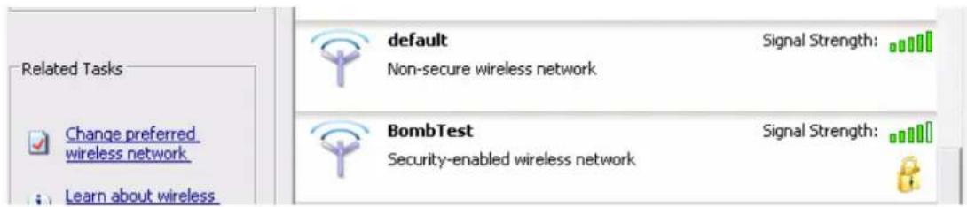
If the client can not access your wireless router, please refresh network list again. However, I still can not fine the device which ssid is "default", please refer to Q3.
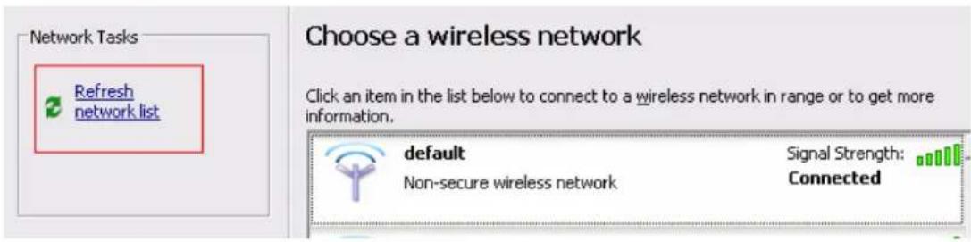
Choose the one that you will want to connect and Connect:
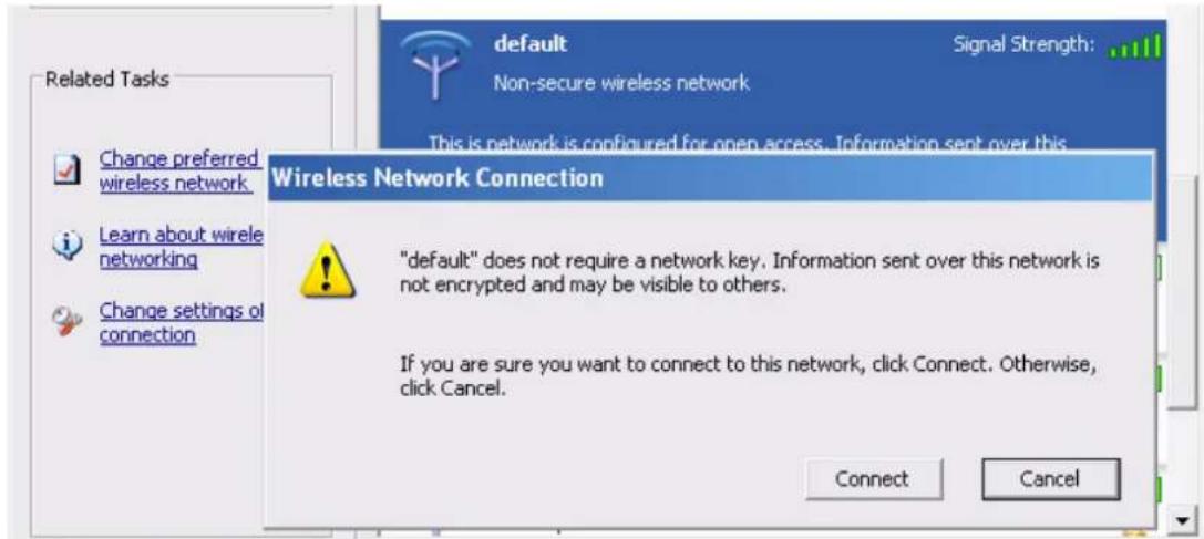
If successfully, the computer will show
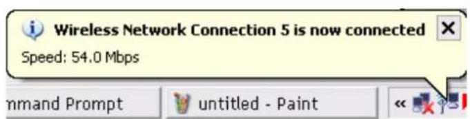
and get ip from router:

- When I use AES encryption of WPA-PSK to connect even if I input the correct pre-share key?
A: First, you must check if the driver of wireless client supports AES encryption. Please refer to the below:
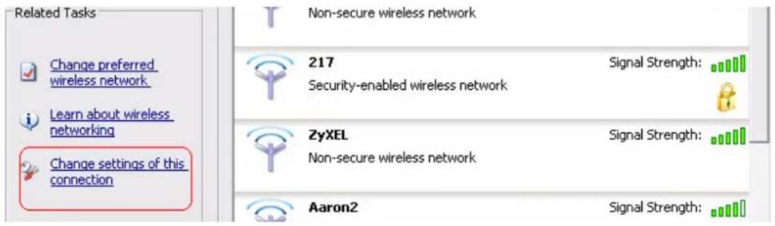
If SSID is default and click "Properties" to check if the driver of wireless client supports AES encryption.
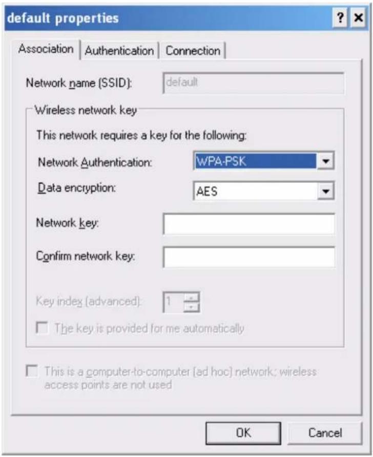
- When I use wireless to connect the router, but I find the signal is very low even if I am close to the router?
A: Please check if the wireless client is normal, first. If yes, please send the unit to the seller and verify what the problem is.
- Air Live® Powered by OvisLink Corp.
- GW-300R
- User's Manual
- Copyright & Disclaimer
- Trademarks
- FCC Interference Statement
- CE Declaration of Conformity
- Table of Contents
- Introduction....1
- Getting Start 8
- 3.Making Configuration....14
- Appendices and Index....70
- FAQ and Troubleshooting....84
- 1
- Introduction
- Packing List
- Spec Summary Table
- Hardware Configuration
- LED indicators
- Procedure for Hardware Installation
- 2
- Getting Start
- Setup mode
- Advanced mode Setup.
- Quick Wizard Install mode Setup
- Wireless Setting.
- Auto Detect WAN Service.
- 3
- Making Configuration
- Login to Configure from Wizard
- Step 1:
- Step 2:
- Step 3:
- Step 4:
- Step 5:
- System Status
- Advanced
- Basic Setting
- Primary Setup – WAN Type, Virtual Computers
- DHCP Server
- DHCP Client List:
- .3.1.3 Wireless 3
- WEP :
- WPA-PSK
- Fill in the key, Ex 12345678
- WPA
- WPA2-PSK(AES)
- WPA2(AES)
- WPA-PSK /WPA2-PSK
- WPA/WPA2
- .3.1.4 Change Password 3
- Forwarding Rules
- .3.2.1 Virtual Server 3
- Special AP
- Miscellaneous Items
- UpnP Setting
- Security Settings
- Packet Filters
- Example 2:
- Example 1:
- Domain filters
- Example:
- URL Blocking
- Internet Access Control
- MAC control
- Miscellaneous Items
- Remote Administrator Host/Port
- Administrator Time-out
- SPI Mode
- DoS Attack Detection
- VPN IPSec Pass-Through
- Advanced Settings
- System Time
- System Log
- SNMP
- Enable SNMP
- Routing
- Schedule Rule
- QoS Rule
- Toolbox
- View Log
- Firmware Upgrade
- Backup Setting
- Reset to default
- Reboot
- Miscellaneous Items
- MAC Address for Wake-on-LAN
- Domain Name or IP Address for Test
- Appendices and Index
- 802.1x Setting
- DUT
- DUT and Windows 2000 Radius Server Setup
- Note.
- Windows 2000 RADIUS server Authentication testing:
- DUT authenticate PC2 using PEAP-TLS.
- WPA Settings
- Or Another Configuration:
- Go "Network" and Select "1" and ok
- Back to Connection and Select "123kk.
- 9.Result:
- Method 2:
- FAQ and Troubleshooting
- What can I do when I have some trouble at the first time?
- How do I connect router by using wireless?
- 1.How to start to use wireless?
Brand : AIRLIVE
Model : GW-300R
Category : Router