
SBC635MSSTB - Beer dispenser Summit - Free user manual and instructions
Find the device manual for free SBC635MSSTB Summit in PDF.


| Product Type | Beer Dispenser |
| Brand | Summit |
| Model | SBC635MSSTB |
| Intended Use | Dispensing and storing keg beer |
| Power Supply | 115 V AC, 60 Hz, 15 A, 3-prong grounded outlet |
| Refrigerant | Isobutane (R600a), environmentally friendly but flammable |
| Temperature Range | 0 to 10 °C (32 to 50 °F) |
| Optimum Serving Temperature | 1.1 to 3.3 °C (34 to 38 °F) |
| Maximum Keg Capacity | Up to 1/2 barrel (59 L / 15.5 US gal) |
| Compatible Keg Sizes | 1/2, 1/4, 1/6, 1/8 barrel (except Coors kegs) |
| Recommended CO₂ Pressure | 8 to 10 lb (3.6 to 4.5 kg) |
| Main Functions | Beer dispensing, rapid cooling (Deep Chill), auto defrost, digital display, temperature adjustment, reversible door |
| Control Panel | Digital with ▲/▼ buttons, °C/°F toggle, Deep Chill key |
| Installation Type | Freestanding, not built-in, minimum 10 cm (4 in) clearance on sides, back, and top |
| Door Orientation | Reversible (right or left) |
| Included Accessories | Beer tower, mixed ball valve, CO₂ regulator, CO₂ bottle (if included?), drip tray, faucet handle, casters (two with brakes) |
| Safety | Grounding required, dedicated 15 A circuit, CO₂ precautions (flammable gas), child safety by removing doors before disposal |
| Maintenance and Cleaning | Clean interior with mild detergent, rinse and dry; regular rear dusting; do not use abrasives or solvents |
| Warranty | 1 year parts and labor (contiguous US); compressor warranty 5 years (labor not included) |
Frequently Asked Questions - SBC635MSSTB Summit
User questions about SBC635MSSTB Summit
0 question about this device. Answer the ones you know or ask your own.
Ask a new question about this device
Download the instructions for your Beer dispenser in PDF format for free! Find your manual SBC635MSSTB - Summit and take your electronic device back in hand. On this page are published all the documents necessary for the use of your device. SBC635MSSTB by Summit.
USER MANUAL SBC635MSSTB Summit
Keep proof of original sales date (such as your sales slip) with this manual to establish the warranty period.
Write the Serial Number below. You'll find it on a plate located either on the back of the appliance or on an interior wall.
AVANT UTILISATION, S'IL VOUS PLAÎT LIRE ET SUIVRE LES RÈGLES DE SÉCURITÉ ET INSTRUCTIONS D'UTILISATION.
Before Using for the First Time ....5
Placement and Installation 6 - 10
Choosing the right place ....6
Installation 6
Applications 6
Connecting to power supply 6
Reversing the door swing 7
Installation of accessories 8-10
Operation 11 - 13
Control panel 11
Setting the temperature 11
Switching between Celsius and Fahrenheit 11
'Rapid cooling' function 11
Automatic defrosting 12
Error prompts 12
Normal functioning 12
Dispensing beer 12-13
Understanding beer temperature 13
Beer serving tips 13
Maintenance of the Beer Dispenser 14
Cleaning 14
Out of service 14
Transporting the unit 14
Specifications of beer kegs 14
Disposing of a Worn-Out Appliance 15
Draft Beer Troubleshooting 16 – 17
General Troubleshooting 18
Limited Warranty 19
French version of this manual 20 - 39
IMPORTANT SAFEGUARDS
WARNING!
To reduce the risk of fire, electric shock or injury when using this appliance, follow these basic precautions:
- Read all instructions before using the appliance.
- The appliance must be correctly connected to the power supply.
- Immediately replace worn power cords, loose plugs and faulty power outlets.
- Do not operate your appliance in the presence of explosive fumes.
- Disconnect the appliance from the power supply before cleaning or repairing it. Only a qualified technician should repair it.
- Never stand on top of or inside this appliance, or swing on the door. Avoid putting weight on top of the appliance.
- To reduce likelihood of injury, do not let children play with this appliance
- Do not operate the valve control unless the cylinder is completely installed and connected.
- Do not attempt to repair or replace any part unless this is recommended in this Use and Care Guide. Leave other service matters to qualified technical personnel.
- Keep packing materials away from children as they could become a choking hazard.
- Do not spray or flush the beer dispenser with water, and avoid keeping it in a damp place since this could damage the electrical insulation.
DANGER! Risk of child entrapment!
Child entrapment and suffocation are not problems of the past. Junked or abandoned appliances are still dangerous, even if they will "just sit at the curb for a few days."
Before discarding your old appliance:
• Take off the door.
- Leave the shelves in place so that children may not easily climb inside.
- This appliance is CFC- and HFC-free and contains small quantities of Isobutane (R600a) which is environmentally friendly, but flammable. It does not damage the ozone layer, nor does it increase the greenhouse effect. Care must be taken during transportation and setting up of the appliance that no parts of the cooling system are damaged. Leaking coolant can ignite and may damage the eyes.
In the event of any damage:
- Avoid open flames and anything that creates a spark,
- Disconnect from the electrical power line,
- Air the room in which the appliance is located for several minutes, and
- Contact the Service Department for advice.
- The more coolant there is in an appliance, the larger the room it should be installed in. In the event of a leakage, if the appliance is in a small room, there is the danger of combustible gases building up. For every ounce of coolant at least 325 cubic feet of room space is required. The amount of coolant in the appliance is stated on the data plate on the back of the appliance. It is hazardous for anyone other than an Authorized Service Person to carry out servicing or repairs to this appliance.
- Take serious care when handling, moving, and using the appliance to avoid either damaging the refrigerant tubing or increasing the risk of a leak.
- Replacing component parts and servicing shall be done by factory authorized service personnel so as to minimize the risk of possible ignition due to incorrect parts or improper service.
SAFETY PRECAUTIONS REGARDING ELECTRICAL MATTERS
- Do not pull on the power cord when unplugging the machine. Grasp the plug firmly and pull it straight out of the socket. Do not pull the plug with wet hands.
- Keep the power cord at the back of the appliance to avoid tripping accidents or damage to the cord.
- If the power cord is damaged or frayed, it must be replaced by a qualified service professional.
- Use only a standard three-hole grounded power socket rated above 10A. The socket should not be shared with other appliances.
- Be sure the plug fits firmly into the socket and that the socket is grounded.
- The use of an extension cord is NOT recommended.
- The beer dispenser requires an AC power supply of 110\~120V/60Hz and pulls a current of over 10A. The fuse or circuit breaker should be rated at 15A.
- If the leakage of a combustible gas is detected, turn off the gas valve and open the doors and windows. To reduce the risk of fire caused by a spark, do not pull out the plug of the beer dispenser or of any other electrical device.
SAFETY PRECAUTIONS REGARDING CO₂ (CARBON DIOXIDE) GAS
Always connect the CO_2 cylinder to a regulator! Failure to do so may cause an explosion resulting in possible injury or death when the cylinder valve is opened.
Never connect the CO_2 cylinder directly to the product container.
Always keep CO_2 cylinders away from heat. Store extra cylinders in a cool place (preferably below 70^ ). Securely fasten cylinders with a chain in an upright position when storing.
Never drop or throw a CO_2 cylinder.
Always check the D.O.T. (Department of Transportation) test date on the cylinder neck before installation. If it has been more than 5 years, do not use. Return the cylinder to your gas supplier.
Never connect a product container unless there are at least two safety devices in the pressure system: one on the CO_2 regulator and the other on the product container or in the pressurized gas line.
The recommended pressure for the CO_2 system is 8-10 lbs.
SAVE THESE INSTRUCTIONS
Tips to save energy and maintain optimum performance:
When positioning this unit: If used freestanding, allow 4 inches of clearance on top, at the sides and in the rear for sufficient airflow.
Do not use under a bar or counter.
LOCATION OF PARTS
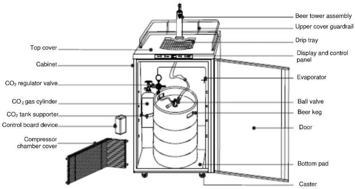
BEFORE USING FOR THE FIRST TIME
The SBC635M is designed for dispensing beer only, and is not recommended for storing perishable foods such as meats or dairy products.
Before connecting the appliance to the power supply, leave it standing for 2 to 3 hours. This allows the refrigerant to drain back into the compressor and reduces the risk of malfunctions in the cooling system caused by shipping.
Clean the appliance thoroughly, especially the interior. (See Maintenance of the Beer Dispenser.) Proper grounding must be ensured to reduce the risk of shock and fire. Do not cut or remove the grounding plug!
TIPS FOR SAVING ENERGY
Try not to open the door too often, especially when the weather is hot and humid. Once you open the door, try to close it as soon as possible.
If possible, disconnect the power before changing a keg of beer.
Keep the unit out of direct sunlight.
Periodically, check that the beer dispenser seals well and that none of the contents prevent the door from closing.
PLACEMENT AND INSTALLATION
Choosing the Right Place
To ensure that your beer dispenser works at the maximum efficiency it was designed for, install it in a location where there are proper air circulation and electrical connections.
Choose a location where the beer dispenser will be away from any heat sources and will not be exposed to direct sunlight.
Remove all packing materials before using the beer dispenser.
Place the machine on a smooth, flat and sturdy surface.
Installation
Your appliance is not designed to operate in enclosed spaces. When placing your unit, make sure you allow at least 4" of clearance at the sides, rear and top to allow for adequate airflow.
Applications
The SBC635M beer dispenser meets UL Standard 250 and is suitable for residential use.
Connecting to Power Supply
Connect this appliance to a 3-prong power supply socket (which has a ground terminal). If you only have a two-prong outlet, have it replaced by a qualified technician with an outlet that meets the local codes
▶▶▶ DO NOT USE AN EXTENSION CORD ◀◀◀
Required nominal voltage and frequency are indicated on the rating plate. The connection to the power supply and grounding has to be made according to current standards and regulations. The appliance resists temporary voltage fluctuations with a tolerance of ±10% .
Once connected, allow the appliance to operate empty for two to three hours before putting a beer keg inside.
Reversing the Door Swing
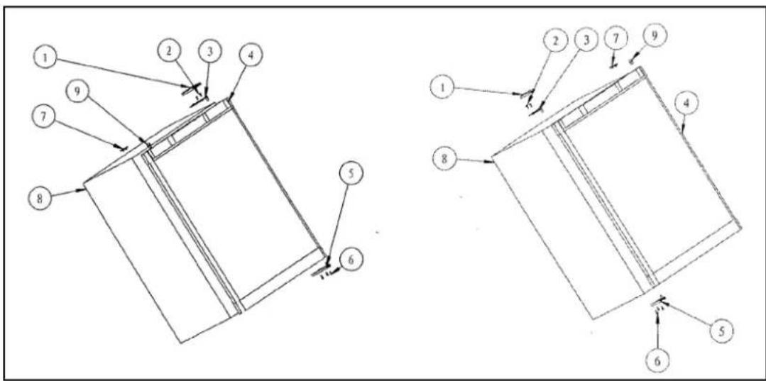
Figure 1 (Default position)
- Upper hinge cover
The beer dispenser can be opened from either the right side or the left. By default, the door hinge is on the right side. If you prefer it on the left, please follow these instructions:
Note: All of the parts that are removed must be kept for the reinstallation of the door.
- Remove the three screws (6) holding lower door hinge (5). Keep hinge for later use.
- Remove the door from the upper hinge (3), and keep the padded surface upward to prevent scratching.
- Remove the upper hinge cover (1), remove the two screws (2), remove the upper hinge (3) and keep it for later use.
- Remove the hole cover (7) and transfer it to the same location on the opposite side.
- Insert the lower door hinge (5) into the left side, fixing the hinge into place by tightening all the screws (6).
- Remove the pin cap (9) from the left side of the upper door frame and then transfer it to the same location on the opposite side.
- Set the door on the lower door hinge (5), keep the door level, then fix the upper hinge (3) to the body (8) by the screws (2).
- Put on the upper hinge cover (1).
Installation of Accessories
Diagram of overall structure
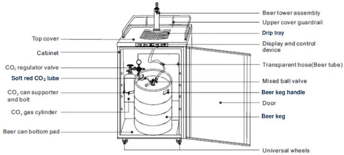
Installation components


Installation steps
1. Install universal wheels:
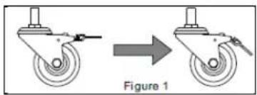
Lock braking guidelines for universal wheels with foot brakes (See Figure 1):
natural_image
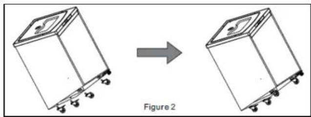
Diagram showing a mechanical device before and after transformation, labeled as Figure 1 (no text or symbols on the diagram itself)Install the two universal wheel washers at the front of the cabinet base, and then install two universal wheels without foot brakes. Next, install the two universal wheels with foot brakes at the back of the cabinet base. Once
installed these rear wheels will keep the unit from moving if you step on the foot brakes (See Figure 2):
natural_image
Diagram showing two views of a mechanical device with wheels, labeled as Figure 2 (no text or symbols on the devices themselves)- Install the beer tower assembly and the mixed ball valve:
a) Plug the beer tower assembly into the top cover of the beer dispenser:
3.0" tower: This does not require a tower buckle. Put beer tower directly over the hole at the top of the beer dispenser's upper surface. Fix the beer tower assembly with screws directly on the upper surface of the beer dispenser. (See Fig. 3).
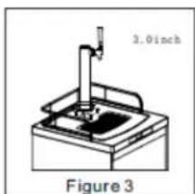
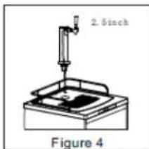
2.5" tower: This requires the tower buckle.
Place the beer tower at the hole in the upper surface of the beer dispenser at an inclination of 60^ , and rotate 60^ clockwise along the card slot. Be sure the tap is facing toward the front of the machine. Attach the beer tower with washers (See Figure 4).
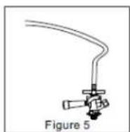
b) Take out the accessories of the mixed ball valve. Attach the transparent hose to the beer outlet of the mixed ball valve (See Figure 5).
natural_image
Simple diagram of a red curved pipe or tube with two valves, labeled Figure 7 (no text or symbols on the diagram itself)- Install CO₂ gas cylinder and CO₂ regulator valve:
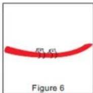
a) Fix the two CO_2 hose clamps on the red CO_2 tube (See Figure 6).
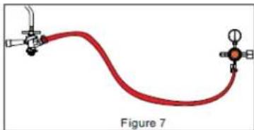
b) Connect the ends of the red CO2 tube respectively to the CO2 intake port of the mixed ball valve and the round outlet of the CO2 regulator valve. Lock these connections firmly with the two clamps on the red CO2 tube (See Figure 7).
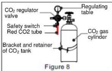
c) Using the wrench, tighten the CO2 regulator table valve with the hex nut port to the gas outlet of the CO2 tank (See Figure 8).
d) Place the CO2 tank and CO2 regulator valve component into the cabinet and fix the CO_2 tank with tank bracket and bolt (See Figure 8).
natural_image
Two-step diagram showing hands using a tool to adjust or install a mechanical component, labeled Figure 9 (no text or symbols on the diagrams themselves)- Install the beer keg:
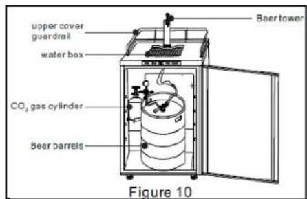
Place the beer keg into the cabinet and firmly connect the keg's opening to the connection port of the mixed ball valve (See Figure 10).
Note: To place a keg into the cabinet, use the keg handle to move the keg to the front of the open beer dispenser, then carefully tip the keg so that the raised bottom edge contacts the edge of the cabinet. Finally, lift the keg handle to raise the keg to the level of the floor of the cabinet and push the keg into place.
- Install tap handle and beer tap:
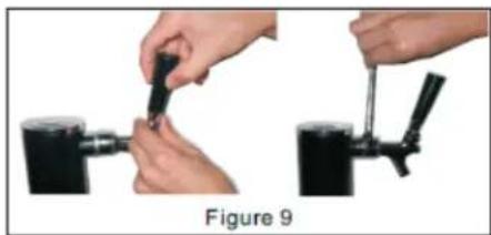
Screw the tap handle clockwise into the beer tap to make a firm connection. Then connect the tap to the beer tower components and tighten with a wrench (See Figure 9).
- Install upper cover guardrail and drip tray:
Set the upper cover guardrail and drip tray on top of the beer dispenser (See Figure 10).
Notes:
- When replacing the beer keg, first turn off the safety switch on the CO_2 regulator valve and remove the mixed ball valve to take out the keg.
- When replacing the CO2 gas cylinder, remember to turn off the main switch of the CO2 gas cylinder and the safety switch on the CO2 regulator valve. Afterwards, use a wrench to loosen the hexagonal nut port connecting the CO2 regulator valve with the CO2 tank. Then, using a wrench, remove the fixed bolt of the CO2 tank to take out the CO_2 tank.
- During the installation process, be sure that all parts are connected tightly and that there are no gas leaks.
- When connecting the hose to the connection port, you can dip the ends into warm water to make the connection easier.
- If the high-pressure compressed gas in the CO_2 tank is not handled properly, it could be dangerous:
a. Make a note of the D.O.T. testing date on the cylinder neck before installation. If it is more than 5 years old, don't use the product. Return it to the gas supplier.
b. Keep gas cylinder away from heat sources. Unused cylinders should be placed upright in a cool, ventilated place (preferably at 70^ F).
OPERATION
Control Panel
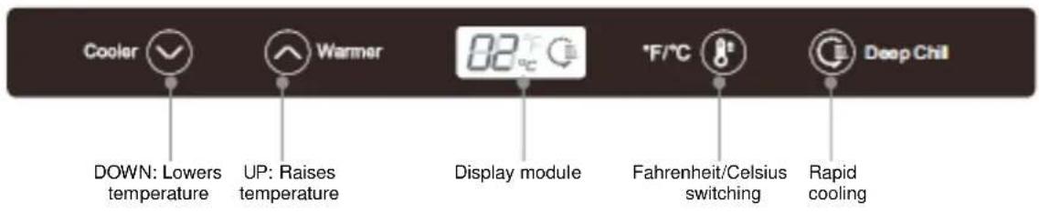
The control panel is located just above the door, and looks like this:
Setting the Temperature
Adjust the DOWN or UP button on the control panel until the display module shows the desired temperature.
The display module shows the set temperature, and the temperature-controlled range varies from 32 to 50^ (0 to 10^ ).
The display module shows 5^ C at the initial power up. Each press of the DOWN or UP button decreases or increases the temperature displayed by 1^ C ( 1^ F).
The optimal temperature for the storage and distribution of beer is 34 - 38°F (1.1 to 3.3°C.
Switching between Celsius and Fahrenheit
You can switch between a Celsius and Fahrenheit temperature display by pressing the °F/°C button. When the displayed temperature is in Celsius, the “°C” symbol will be illuminated; with a Fahrenheit display, “°F” will be illuminated.
'Rapid Cooling' Function
Press the Deep Chill button to enter the Rapid Cooling state. The "rapid cooling" icon on the display module will light and the temperature display will read "00". After entering the Rapid Cooling mode, the appliance will work continuously for 24 hours and the icon will remain lit. After that time, the icon will turn off and the appliance will return to its former state.
You can cancel the Rapid Cooling mode any time during the 24 hour period by simply pressing the Deep Chill button again.
Note: The Rapid Cooling function is normally used only for cooling the first keg of beer in the appliance, when that keg is to be used as soon as possible. To prevent over-cooling the beer, do not use Rapid Cooling for succeeding kegs.
Automatic Defrosting
There is usually no need to defrost the beer dispenser because the ice deposited on the inner back wall is automatically defrosted. Ice deposits on the inner back wall during compressor operation. Later on, when the compressor is not operating, the ice defrosts and water drains through the outlet in the inner back wall into the drain pan situated above the compressor where it evaporates. If you see water building up in the rear of the unit, check that the drain trough is not clogged. Use a pipe cleaner or a piece of flexible wire. During extremely hot and humid weather, some ice may build up. If necessary, remove contents of the beer dispenser, unplug the unit and allow defrosting. A hair dryer may facilitate the process.
Error Prompts
When the following prompts appear in the display module, there is a failure in the appliance. Although one of the fault conditions occurs, the beer dispenser may still work. However, you should contact our Service Department as soon as possible to obtain advice on handling the situation.
| Prompt | E1 | E4 | E7 |
| Fault | Temperature sensor failure in the refrigerated zone | Defrosting sensor failure in the refrigerator compartment | Ambient temperature sensor fault |
Note: When two or more sensors fail simultaneously, all fault codes will display alternately on the display module. If the ambient temperature and defrost sensors fail, any key may be pressed. The temperature is adjustable. The fault display will be restored after 15 seconds.
Normal Functioning
- If there is a sound of rushing water when the machine is in use, the noise is caused by the refrigerant flowing in the cooling pipes and running through the compressor. This is a normal phenomenon.
- The beer dispenser has no heating function. When the temperature is set higher than the ambient temperature, the machine will not run.
Dispensing Beer
Follow these steps to dispense beer:
- Make sure the beer dispenser is plugged in properly to a 120V, 60Hz, 15 amp grounded AC outlet.
- Place the drip tray under the beer tap.
- Open the beer faucet by pulling the tap towards you quickly and completely to dispense the beer.
-
Increase the pressure if the beer runs too slowly. At the correct pressure and temperature, a 10-oz glass should be filled in 4 seconds.
-
Hold the glass steady at a 45^ angle. When it is 2/3 full, start straightening the glass. Proper foam should be a tight, creamy head and the collar on an average glass should be 3/4" to 1" high.
Note: It is normal to see condensation forming on the tap. It is caused by the difference in temperature between the cold beer and the inner surfaces of the tap when beer is flowing through the line.
Understanding Beer Temperature
The recommended temperature for serving chilled beer is between 38^ and 43^ F. To maintain this temperature in average room conditions of 70^ F, set the thermostat accordingly.
Notes: During the summertime when temperatures are warmer, we recommend that you adjust the control to a cooler setting. Selecting and maintaining the proper temperature inside the refrigerator cabinet is necessary for maintaining the flavor and freshness of beer. Excessively cold or warm temperatures inside the refrigerator cabinet may cause a loss of flavor.
The best temperature for storing a keg is approximately 38^ F.
Sour beer is produced as a result of secondary fermentation above 45^ F.
Beer Serving Tips
The following tips will help you serve the perfect beer. To serve beer from the tap similar to the way it left the vat, check the following:
- Cleanliness (see Maintenance of the Beer Dispenser)
- Temperature (see Setting the Temperature and Understanding Beer Temperature)
- Pressure (The recommended pressure for the CO_2 system is 8-10 lbs.)
- Use only CO_2 gas
MAINTENANCE OF THE BEER DISPENSER
Cleaning
To optimize cooling and to save energy at the same time, dust the back of the beer dispenser periodically.
The interior should be cleaned regularly. Use a soft towel or sponge that has been dampened in a solution of mild detergent. Rinse with clean water and dry with a cloth. Leave the door open for a while to allow the unit to dry thoroughly before turning the power back on.
Do not use a hard brush, steel wool, wire brush, or abrasives such as toothpaste, or organic solvents like alcohol or acetone to clean the beer dispenser.
When cleaning or rinsing the unit, be careful not to let the control panel or any electrical components become wet.
Out of Service
If the machine will be out of service for more than three weeks, unplug it and clean and dry it thoroughly. Allow the door to remain open slightly to prevent the buildup of mold and odors.
Transporting the Unit
Firmly fix any loose items inside the beer dispenser with tape. Tape the door shut so it will not open during transportation.
Loosen the two foot brakes before moving the unit.
Specifications of Beer Kegs
Keg sizes that can be used in your beer dispenser:
| 1/2 barrel | 59 liters | 15.5 gals. | 1,984 oz. | 164 / 12-oz. Glass |
| 1/4 barrel | 30 liters | 7.8 gals. | 992 oz. | 82 / 12-oz. Glass |
| 1/6 barrel | 20 liters | 5.2 gals. | 661 oz. | 55 / 12-oz. Glass |
| 1/8 barrel | 15 liters | 4.0 gals. | 496 oz. | 41 / 12-oz. Glass |
Note: Our beer dispenser accepts almost all brand name 1/2 kegs. However, Coors' kegs do not fit in our unit.
DISPOSING OF A WORN-OUT APPLIANCE
- When your appliance finally wears out, dispose of it.
- Before you dispose of an old appliance: Take the door or doors off but leave any shelves or drawers in place so that children cannot easily climb inside.
- The refrigerating system of the appliance is filled with refrigerant and insulating substances that should be recycled separately. Either have a licensed appliance repair company or dealer remove the appliance or call your local recycling office for the appropriate disposal information.
- For the sake of environmental protection, when moving the appliance, be careful not to damage the rear wall (the condenser unit or the tubes) or any part of the refrigeration system inside the appliance.
- This beer dispenser is 100% CFC-free, but the coolant is under pressure and inflammable, and puncturing the sealed system could be dangerous. The coolant used in the sealed system is non-toxic.
- Many older appliances may contain refrigerants that are harmful to the environment, and should be recycled by a lawfully licensed company.
DRAFT BEER TROUBLESHOOTING
| Problem | Cause | Correction |
| Beer is cloudy: The beer in the glass appears hazy and not clear. | Excessively low temperatures may cause hazy or cloudy beer, particularly when the beer lies in the cold coil for long periods of time. | Drain a few ounces before drinking. |
| Raise the temperature setting of the unit. | ||
| Glasses may not have been cleaned properly. | Do not wash beer glasses together with glasses that have contained milk or any other fatty substance. An excessive amount of germicide build-up may also leave a fatty film, which will cause beer to go flat. | |
| It is preferable to steam and sterilize glasses where health laws permit. | ||
| Wash glasses thoroughly with a good detergent to remove all fatty substances (e.g., lipstick). | ||
| Do not use soap. | ||
| Do not wipe the glasses dry. Permit glasses to air-dry by placing them on a wire rack or corrugated metal sheet. | ||
| Rinse the glasses in fresh cold water just before serving beer. It is best to serve beer in a wet glass. | ||
| Improper drawing of beer into glass | Open the faucet quickly and completely; proper foam should be a tight creamy head. The collar on the average glass should be 3/4" to 1" high. Beer drawn without a head has the appearance of being flat. | |
| Not enough pressure | Increase the pressure if beer runs too slowly. The correct flow should fill a 10-oz glass in 4 seconds (approx. 8 oz of liquid). Check the pressure source to determine whether there are obstructions in the air line. Replace a sluggish air source or the CO2 regulator and gauge. The tank pressure must always be higher than the pressure used on the keg. Always apply pressure to the keg before drawing beer. | |
| Beer has off taste: Often bitter and bite-y; sometimes completely lacking flavor and zest. It may also have an oily or foul odor which may carry an unpleasant taste. | Improper cleaning of the tap | Brush and clean the tap properly. It should be scoured using a detergent, then rinsed clean. |
| Contaminated air line | Beer tube should be examined. If contaminated, it should be replaced. | |
| Condensation is forming on the tap. | It is normal to see condensation forming on the tap. It is caused by a difference in temperature between the cold beer and the surfaces of the tap when beer is flowing through the line. Beer that is left in the tap is not cooled by the beer dispenser. | After a period of non-use, a few ounces should be drained before drinking. |
GENERAL TROUBLESHOOTING
If there is a problem with the beer dispenser itself, see if you can find it listed in the chart below. You may be able to save yourself the cost of a service visit.
| Problem | Possible Cause |
| The beer dispenser doesn’t work. | Power supply not firmly connected.Supplied voltage is too low.Tripped circuit breaker or blown fuse. |
| The machine switches on and off frequently. | Indoor temperature is higher than usual.Machine door is opened frequently.Door is not completely closed.Temperature control is not set correctly. |
| Door cannot be closed properly. | Beer keg not properly placed.Beer dispenser is not level.Door was reversed and re-installed incorrectly.Metal plate or beer kegs are out of place. |
| Noise Rushing noise may be | the sound of refrigerant flow, which is normal.As each cycle ends, the gurgle of refrigerant flow may be heard.Contraction and expansion of inner wall may cause pops and crackles. |
LIMITED WARRANTY
ONE-YEAR LIMITED WARRANTY
Within the 48 contiguous United States, for one year from the date of purchase, when this appliance is operated and maintained according to instructions attached to or furnished with the product, warrantor will pay for factory-specified parts and repair labor to correct defects in materials or workmanship. Service must be provided by a designated service company. Outside the 48 states, all parts are warranted for one year from manufacturing defects. Plastic parts, shelves and cabinets are warranted to be manufactured to commercially acceptable standards, and are not covered from damage during handling or breakage.
5-YEAR COMPRESSOR WARRANTY
- The compressor is covered for 5 years.
- Replacement does not include labor.
ITEMS WARRANTOR WILL NOT PAY FOR:
- Service calls to correct the installation of your appliance, to instruct you how to use your appliance, to replace or repair fuses or to correct wiring or plumbing.
- Service calls to repair or replace appliance light bulbs or broken shelves. Consumable parts (such as filters) are excluded from warranty coverage.
- Damage resulting from accident, alteration, misuse, abuse, fire, flood, acts of God, improper installation, installation not in accordance with electrical or plumbing codes, or use of products not approved by warrantor.
- Replacement parts or repair labor costs for units operated outside the United States.
- Repairs to parts or systems resulting from unauthorized modifications made to the appliance.
- Expenses for travel and transportation for product service in remote locations.
- The removal and reinstallation of your appliance if it is installed in an inaccessible location or is not installed in accordance with published installation instructions.
DISCLAIMER OF IMPLIED WARRANTIES; LIMITATION OF REMEDIES
CUSTOMER'S SOLE AND EXCLUSIVE REMEDY UNDER THIS LIMITED WARRANTY SHALL BE PRODUCT REPAIR AS PROVIDED HEREIN. IMPLIED WARRANTIES, INCLUDING WARRANTIES OF MERCHANTABILITY OR FITNESS FOR A PARTICULAR PURPOSE, ARE LIMITED TO ONE YEAR. WARRANTOR SHALL NOT BE LIABLE FOR INCIDENTAL OR CONSEQUENTIAL DAMAGES. SOME STATES DO NOT ALLOW THE EXCLUSION OR LIMITATION OF INCIDENTAL OR CONSEQUENTIAL DAMAGES, OR LIMITATIONS ON THE DURATION OF IMPLIED WARRANTIES OF MERCHANTABILITY OR FITNESS, SO THESE EXCLUSIONS OR LIMITATIONS MAY NOT APPLY TO YOU. THIS WARRANTY GIVES YOU SPECIFIC LEGAL RIGHTS AND YOU MAY ALSO HAVE OTHER RIGHTS, WHICH VARY FROM STATE TO STATE.
WARNING! This product may contain chemicals known to the state of California to cause cancer or birth defects or other reproductive harm. For more information, visit: www.summitappliance.com/prop65
Chemicals known by the manufacturer to be present in this product in concentrations higher than threshold limits: NONE.
FELIX STORCH, INC.
770 Garrison Avenue
Bronx, NY 10474
Phone: (718) 893-3900
Fax: (844) 478-8799
www.summitappliance.com

For parts and accessory ordering, troubleshooting and helpful hints, visit: www.summitapplianceparts.com
Revised March 2015
TABLE DES MATIÈRES
natural_image
Diagram showing a mechanical device before and after transformation, labeled as Figure 1 (no text or symbols on the diagram itself)natural_image
Diagram showing two views of a washing machine before and after transformation, labeled as Figure 2 (no text or symbols on the devices themselves)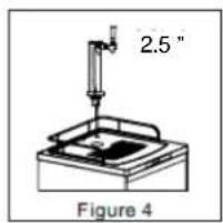
natural_image
Simple diagram of a red curved line with two valves and a valve, labeled Figure 7 (no text or symbols on the diagram itself)natural_image
Two-step diagram showing hands using a tool to adjust or install a mechanical component, labeled Figure 9 (no text or symbols on the diagrams themselves)www.summitappliance.com/support
Révisé mars 2015
- AVANT UTILISATION, S'IL VOUS PLAÎT LIRE ET SUIVRE LES RÈGLES DE SÉCURITÉ ET INSTRUCTIONS D'UTILISATION.
- IMPORTANT SAFEGUARDS
- WARNING!
- To reduce the risk of fire, electric shock or injury when using this appliance, follow these basic precautions:
- DANGER! Risk of child entrapment!
- SAFETY PRECAUTIONS REGARDING ELECTRICAL MATTERS
- SAFETY PRECAUTIONS REGARDING CO₂ (CARBON DIOXIDE) GAS
- SAVE THESE INSTRUCTIONS
- Tips to save energy and maintain optimum performance:
- LOCATION OF PARTS
- BEFORE USING FOR THE FIRST TIME
- TIPS FOR SAVING ENERGY
- PLACEMENT AND INSTALLATION
- Choosing the Right Place
- Installation
- Applications
- Connecting to Power Supply
- ▶▶▶ DO NOT USE AN EXTENSION CORD ◀◀◀
- Reversing the Door Swing
- Installation of Accessories
- Installation steps
- Install universal wheels:
- Notes:
- OPERATION
- Control Panel
- Setting the Temperature
- Switching between Celsius and Fahrenheit
- 'Rapid Cooling' Function
- Automatic Defrosting
- Error Prompts
- Normal Functioning
- Dispensing Beer
- Understanding Beer Temperature
- Beer Serving Tips
- MAINTENANCE OF THE BEER DISPENSER
- Cleaning
- Out of Service
- Transporting the Unit
- Specifications of Beer Kegs
- DISPOSING OF A WORN-OUT APPLIANCE
- GENERAL TROUBLESHOOTING
- LIMITED WARRANTY
- ONE-YEAR LIMITED WARRANTY
- 5-YEAR COMPRESSOR WARRANTY
- ITEMS WARRANTOR WILL NOT PAY FOR:
- DISCLAIMER OF IMPLIED WARRANTIES; LIMITATION OF REMEDIES
- TABLE DES MATIÈRES
Brand : Summit
Model : SBC635MSSTB
Category : Beer dispenser