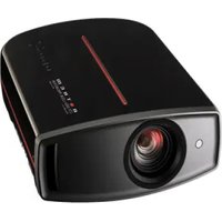
LTX 500v - Projector Anthem - Free user manual and instructions
Find the device manual for free LTX 500v Anthem in PDF.


| Display Technology | LCoS 3 x 0.70 inch |
| Native Resolution | 1920 x 1080 pixels (Full HD 1080p) |
| Aspect Ratio | 16:9 |
| Brightness | 900 lumens ANSI |
| Contrast | 50,000:1 (full on/off) |
| Color Depth | 8 bits |
| Optical Zoom | 2x motorized |
| Focus | Motorized |
| Lens Shift | Motorized horizontal and vertical |
| Throw Ratio | 1.38:1 to 2.79:1 |
| Image Size | 152 cm to 508 cm (60 to 200 inches) |
| Lamp | UHP 200W (ref. BHL-5010-S) |
| Lamp Life | 2,000 h (2,500 h in Eco mode) |
| Connectivity | 2x HDMI 1.3, component, S-Video, RCA composite, RS-232 |
| 12V Trigger Outputs | 2 |
| Noise Level | 19 dB |
| Power Consumption | 280 W (110-240 V) |
| Dimensions (H x W x D) | 15 x 44 x 37 cm |
| Weight | 13.9 kg |
| Certification | THX |
Frequently Asked Questions - LTX 500v Anthem
- 2x HDMI 1.3
- Component input (VGA/YPbPr)
- S-Video
- Composite video RCA
- RS-232 port for home automation control
User questions about LTX 500v Anthem
0 question about this device. Answer the ones you know or ask your own.
Ask a new question about this device
Download the instructions for your Projector in PDF format for free! Find your manual LTX 500v - Anthem and take your electronic device back in hand. On this page are published all the documents necessary for the use of your device. LTX 500v by Anthem.
USER MANUAL LTX 500v Anthem
MANUEL D'INSTRUCTIONS
Enter below the serial No. which is located on the side of the cabinet. Retain this information for future reference.
Model No. LTX 500v
Serial No.
This product has a High Intensity Discharge (HID) lamp that contains mercury.
Disposal of these materials may be regulated in your community due to environmental considerations. For disposal or recycling information, please contact your local authorities or for USA, the Electronic Industries Alliance: http://www.eiae.org.
WARNING:
TO PREVENT FIRE OR SHOCK HAZARDS, DO NOT EXPOSE THIS APPLIANCE TO RAIN OR MOISTURE.
WARNING:
THIS APPARATUS MUST BE GROUNDED.
CAUTION:
To reduce the risk of electric shock, do not remove cover. Refer servicing to qualified service personnel.
This projector is equipped with a 3-blade grounding type plug to satisfy FCC rule. If you are unable to insert the plug into the outlet, contact your electrician.
FCC INFORMATION (U.S.A. only)
CAUTION:
Changes or modifications not approved by Anthem Electronics could void the user's authority to operate the equipment.
NOTE:
This equipment has been tested and found to comply with the limits for Class B digital devices, pursuant to Part 15 of the FCC Rules. These limits are designed to provide reasonable protection against harmful interference in a residential installation. This equipment generates, uses, and can radiate radio frequency energy and, if not installed and used in accordance with the instructions, may cause harmful interference to radio communications. However, there is no guarantee that interference will not occur in a particular installation. If this equipment does cause harmful interference to radio or television reception, which can be determined by turning the equipment off and on, the user is encourage to try to correct the interference by one or more of the following measures:
● Reorient or relocate the receiving antenna.
- Increase the separation between the equipment and receiver.
- Connect the equipment into an outlet on a circuit different from that to which the receiver is connected.
- Consult the dealer or an experienced radio/TV technician for help.
MACHINE NOISE INFORMATION (Germany only)
Changes Machine Noise Information Ordinance 3. GSGV, January 18, 1991: The sound pressure level at the operator position is equal or less than 19 dB (A) according to ISO 7779.
About the installation place
Do not install the projector in a place that cannot support its weight securely.
If the installation place is not sturdy enough, the projector could fall or overturn, possibly causing personal injury.
IMPORTANT SAFEGUARDS
Electrical energy can perform many useful functions. This unit has been engineered and manufactured to assure your personal safety. But IMPROPER USE CAN RESULT IN POTENTIAL ELECTRICAL SHOCK OR FIRE HAZARD. In order not to defeat the safeguards incorporated into this product, observe the following basic rules for its installation, use and service. Please read these Important Safeguards carefully before use.
- All the safety and operating instructions should be read before the product is operated.
- The safety and operating instructions should be retained for future reference.
- All warnings on the product and in the operating instructions should be adhered to.
- All operating instructions should be followed.
- Place the projector near a wall outlet where the plug can be easily unplugged.
- Unplug this product from the wall outlet before cleaning. Do not use liquid cleaners or aerosol cleaners. Use a damp cloth for cleaning.
- Do not use attachments not recommended by the product manufacturer as they may be hazardous.
- Do not use this product near water. Do not use immediately after moving from a low temperature to high temperature, as this causes condensation, which may result in fire, electric shock, or other hazards.
- Do not place this product on an unstable cart, stand, or table. The product may fall, causing serious injury to a child or adult, and serious damage to the product. The product should be mounted according to the manufacturer's instructions, and should use a mount recommended by the manufacturer.
- When the product is used on a cart, care should be taken to avoid quick stops, excessive force, and uneven surfaces which may cause the product and cart to overturn, damaging equipment or causing possible injury to the operator.
PORTABLE CART WARNING (symbol provided by RETAC)

S3126A
- Slots and openings in the cabinet are provided for ventilation. These ensure reliable operation of the product and protect it from overheating. These openings must not be blocked or covered. (The openings should never be blocked by placing the product on bed, sofa, rug, or similar surface. It should not be placed in a built-in installation such as a bookcase or rack unless proper ventilation is provided and the manufacturer's instructions have been adhered to.)
- To allow better heat dissipation, keep a clearance between this unit and its surrounding as shown below. When this unit is enclosed in a space of dimensions as shown below, use an air-conditioner so that the internal and external temperatures are the same.
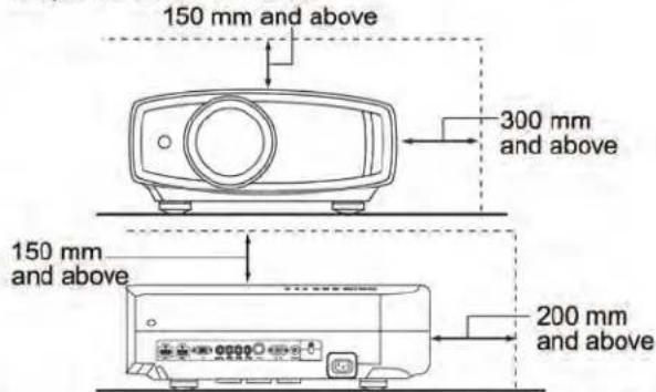
- power source indicated on the label. If you are not sure of the type of power supply to your home, consult your product dealer or local power company.
- This product is equipped with a three-wire plug. This plug will fit only into a grounded power outlet. If you are unable to insert the plug into the outlet, contact your electrician to install the proper outlet. Do not defeat the safety purpose of the grounded plug.
- Power-supply cords should be routed so that they are not likely to be walked on or pinched by items placed upon or against them. Pay particular attention to cords at doors, plugs, receptacles, and the point where they exit from the product.
- For added protection of this product during a lightning storm, or when it is left unattended and unused for long periods of time, unplug it from the wall outlet and disconnect the cable system. This will prevent damage to the product due to lightning and power line surges.
- Do not overload wall outlets, extension cords, or convenience receptacles on other equipment as this can result in a risk of fire or electric shock.
- Never push objects of any kind into this product through openings as they may touch dangerous voltage points or short out parts that could result in a fire or electric shock. Never spill liquid of any kind on the product.
- Do not attempt to service this product yourself as opening or removing covers may expose you to dangerous voltages and other hazards. Refer all service to qualified service personnel.
- Unplug this product from the wall outlet and refer service to qualified service personnel under the following conditions:
a) When the power supply cord or plug is damaged.
b) If liquid has been spilled, or objects have fallen on the product.
c) If the product has been exposed to rain or water.
d) If the product does not operate normally by following the operating instructions. Adjust only those controls that are covered by the Operation Manual, as an improper adjustment of controls may result in damage and will often require extensive work by a qualified technician to restore the product to normal operation.
e) If the product has been dropped or damaged in any way.
f) When the product exhibits a distinct change in performance - this indicates a need for service.
- When replacement parts are required, be sure the service technician has used replacement parts specified by the manufacturer or with same characteristics as the original part. Unauthorized substitutions may result in fire, electric shock, or other hazards.
- Upon completion of any service or repairs to this product, ask the service technician to perform safety checks to determine that the product is in proper operating condition.
- The product should be placed more than one foot away from heat sources such as radiators, heat registers, stoves, and other products (including amplifiers) that produce heat.
- When connecting other products such as VCR's, and DVD players, you should turn off the power of this product for protection against electric shock.
- Do not place combustibles behind the cooling fan. For example, cloth, paper, matches, aerosol cans or gas lighters that present special hazards when over heated.
- Do not look into the projection lens while the illumination lamp is turned on. Exposure of your eyes to the strong light can result in impaired eyesight.
- Do not look into the inside of this unit through vents (ventilation holes), etc. Do not look at the illumination lamp directly by opening the cabinet while the illumination lamp is turned on. The illumination lamp also contains ultraviolet rays and the light is so powerful that your eyesight can be impaired.
- Do not drop, hit, or damage the light-source lamp (lamp unit) in any way. It may cause the light-source lamp to break and lead to injuries. Do not use a damaged light source lamp. If the light-source lamp is broken, ask your dealer to repair it. Fragments from a broken light-source lamp may cause injuries.
- The light-source lamp used in this projector is a high pressure mercury lamp. Be careful when disposing of the light-source lamp. If anything is unclear, please consult your dealer.
- Do not ceiling-mount the projector to a place which tends to vibrate; otherwise, the attaching fixture of the projector could be broken by the vibration, possibly causing it to fall or overturn, which could lead to personal injury.
- Use only the accessory cord designed for this product to prevent shock.
\*DO NOT allow any unqualified person to install the unit.
Be sure to ask your dealer to install the unit (e.g. attaching it to the ceiling) since special technical knowledge and skills are required for installation. If installation is performed by an unqualified person, it may cause personal injury or electrical shock.
Safety Precautions (Continued)
POWER CONNECTION
The power supply voltage rating of this product is AC110V - AC240V. Use only the power cord designated by our dealer to ensure Safety and EMC.
Ensure that the power cable used for the projector is the correct type for the AC outlet in your country. Consult your product dealer.
WARNING:
Do not cut off the main plug from this equipment.
If the plug fitted is not suitable for the power points in your home or the cable is too short to reach a power point, then obtain an appropriate safety approved extension lead or adapter or consult your dealer.
If nonetheless the mains plug is cut off, dispose of the plug immediately, to avoid a possible shock hazard by inadvertent connection to the main supply. If a new main plug has to be fitted, then follow the instruction given below.
WARNING:
THIS APPARATUS MUST BE GROUNDED.
IMPORTANT (Europe only):
The wires in the mains lead on this product are colored in accordance with the following cord:
Green-and-yellow : Earth
Blue : Neutral
Brown : Live
As these colors may not correspond with the colored making identifying the terminals in your plug, proceed as follows:
The wire which is colored green-and-yellow must be connected to the terminal which is marked M with the letter E or the safety earth or colored green or green-and-yellow.
The wire which is colored blue must be connected to the terminal which is marked with the letter N or colored black.
The wire which is colored brown must be connected to the terminal which is marked with the letter L or colored red.
Dear Customer,
This apparatus is in conformance with the valid European directives and standards regarding electromagnetic compatibility and electrical safety.
North American representative:
Anthem Electronics Inc.
205 Annagem Blvd. Mississauga, ON L5T 2V1
Canada
ENGLISH
Information for Users on Disposal of Old Equipment and Batteries
Products

Battery
[European Union only]
These symbols indicate that equipment with these symbols should not be disposed of as general household waste. If you want to dispose of the product or battery, please consider the collection systems or facilities for appropriate recycling.
Notice: The sign Pb below the symbol for batteries indicates that this battery contains lead.
DEUTSCH
Merk: Tegnet Pb under symbolet for batterier, viser at batteriet inneholder bly.
РУССКИЙ
THX CertificationTHX Certification
THX
THX Certification
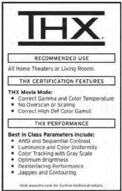
THX Ltd. was founded by filmmaker George Lucas to improve the cinema and home entertainment experience through strict engineering standards and breakthrough technologies. THX has leveraged more than 25 years of filmmaking, cinema design and post-production expertise to partner with Anthem Electronics to engineer a best-in-class home theater projector.
With a strict focus on image quality and signal processing performance, THX certification promises that this Anthem Electronics projector is capable of presenting a wide range of video content at maximum resolutions with the correct color and luminance levels. In addition, THX has created a battery of signal processing tests that challenge the projector's scaling, motion conversion and de-interlacing capabilities. This type of in-depth analysis predicts how the projector will present a variety of high definition and standard definition content.
The Anthem Electronics projector also features THX Movie Mode, a pre-calibrated video setting for watching movies on DVD, Blu-ray HD or broadcast television. This playback feature is designed to recreate the cinema experience at home by setting the display's gamma, luminance, color temperature and other settings to mirror those used by filmmakers in post-production. THX Movie Mode also ensures projector brightness is optimal for large screen viewing.

For detailed information about the Imaging Science Foundation (ISF), please visit the website at http://www.imagingscience.com
Contents
Getting Started
Safety Precautions....2
THX Certification....9
isf information....9
Contents....10
How to Read this Manual/Accessories/
Optional Accessories ....11
About this Manual ....11
Check the Accessories 11
Optional Accessories.... 11
Controls and features....12
How to Use the Remote Control ....15
Loading Batteries....15
Effective Range of Remote Control Unit......15
Preparation
Selecting Connecting Devices....16
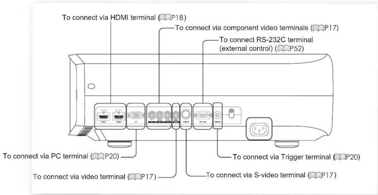
Connecting....17
Connecting via Video Cable and S-Video
Cable....17
Connecting via Component Video Cable.....17
Connecting via HDMI Cable....18
Connecting via HDMI-DVI Conversion Cable...18
Connecting via SCART-RCA Cable....19
Connecting via RGB Video Cable....19
Connecting via PC Cable....20
Connecting via Trigger Cable....20
Installing the Projector and Screen ....21
Set Angle 21
Shift 21
Screen Size and Projection Distance .....22
Basic Operation
Projecting Image....24
Convenient Features during Projection ..... 26
Setting the Screen Size 26
Masking the Surrounding Area of an Image. ....26
Settings
The structure of the Settings menu 28
Setting Menu 30
Procedures for Menu Operation ....30
Setting Menu 31
Customizing Projected Images 42
Changing the Initial Setting of Picture Mode . 42
Registering User-defined Picture Mode .....43
Registering User-defined Picture Mode from the
Menu 43
Troubleshooting
Troubleshooting 44
What to Do When these Messages
Are Displayed 46
About Warning Indicators 47
Actions to Be Taken for Warning Mode .....47
Replacing the Lamp 48
Procedure for Lamp Replacement 48
Resetting Lamp Time ....50
Cleaning and Replacing the Filter ....51
Others
RS-232C Interface 52
RS-232C Specifications ....52
Command Format ....52
RS-232C Communication Examples .... 55
Copyright and Caution ....56
About Trademarks and Copyright ....56
Caution 56
Mounting this Unit ....57
Specifications 58
Dimensions 60
Limited Warranty....61
How to Read this Manual/Accessories/Optional Accessories
About this Manual
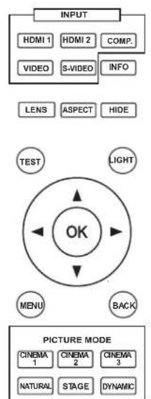
flowchart
graph TD
    A["INPUT"] --> B["HDMI 1"]
    A --> C["HDMI 2"]
    A --> D["COMP."]
    A --> E["VIDEO"]
    A --> F["S-VIDEO"]
    A --> G["INFO"]
    A --> H["LENS"]
    A --> I["ASPECT"]
    A --> J["HIPE"]
    K["TEST"] --> L["OK"]
    M["LIGHT"] --> L
    N["MENU"] --> L
    O["BACK"] --> L
    P["PICTURE MODE"] --> Q["CINEMA 1"]
    P --> R["CINEMA 2"]
    P --> S["CINEMA 3"]
    P --> T["NATURAL"]
    P --> U["STAGE"]
    P --> V["DYNAMIC"]
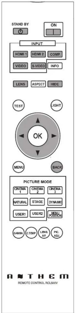
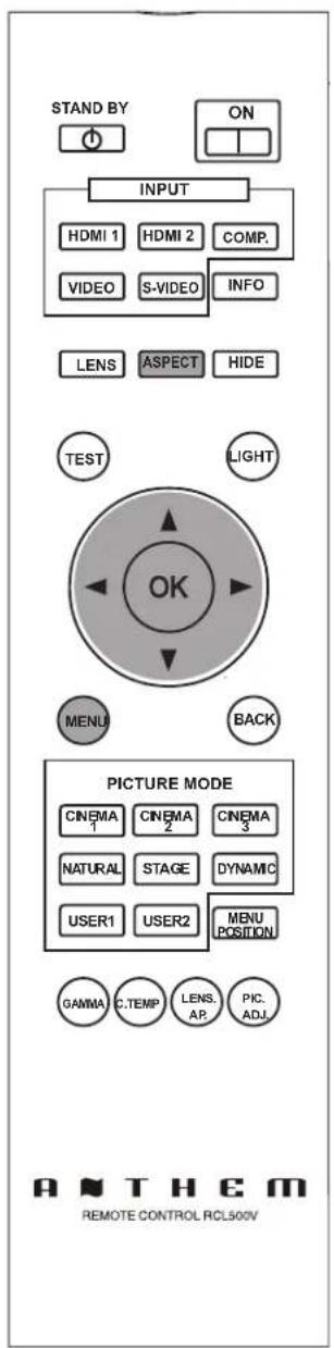
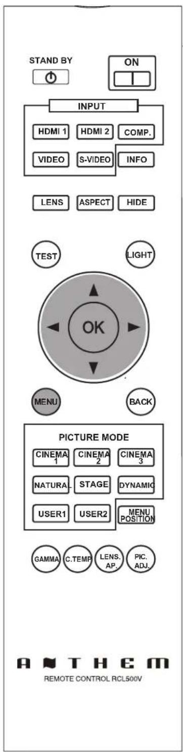
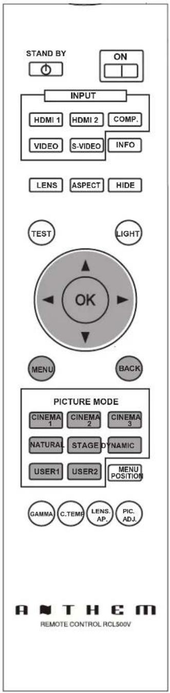
Buttons to be used are colored in a darker shade.
This manual mainly describes the operating method using the remote control.
- Buttons on the remote control are described as [Button Name].
- Items on the menu are described as "Selection Item".
■ Conventions in this manual

Describes the limitations of the functions or usage.

Indicates good-to-know information.

Describes operational precautions.

Indicates relevant pages for reference.
Check the Accessories
Remote Control 1 piece
AAA size Batteries 2 pieces
Power Cord For the US market (2 m) 1 piece
- Instruction manual and other printed materials are also included.
Optional Accessories
Please check with your authorized dealer for details.
● Replacement Lamp: BHL5010-S (Lamp Unit)
● Replacement Filter (black in appearance): PB006560999 (Inner Filter)
Controls and features
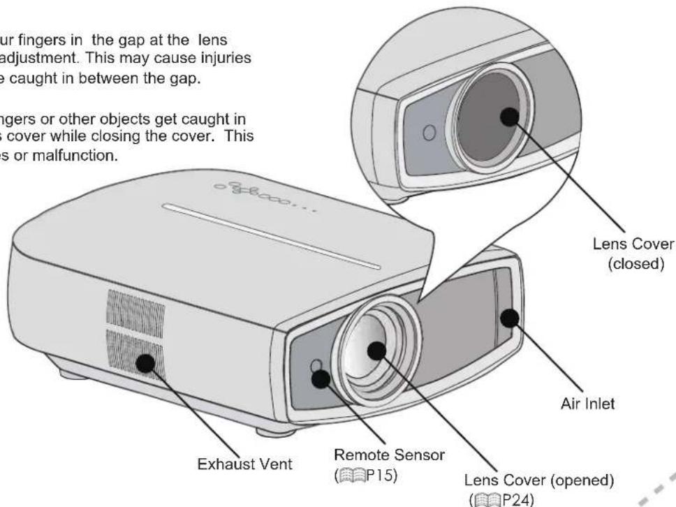
■ Front Side/Left Side

CAUTION
- Do not place your fingers in the gap at the lens during lens shift adjustment. This may cause injuries if your fingers are caught in between the gap. (Ⅱ)P25
- Do not let your fingers or other objects get caught in between the lens cover while closing the cover. This can cause injuries or malfunction.
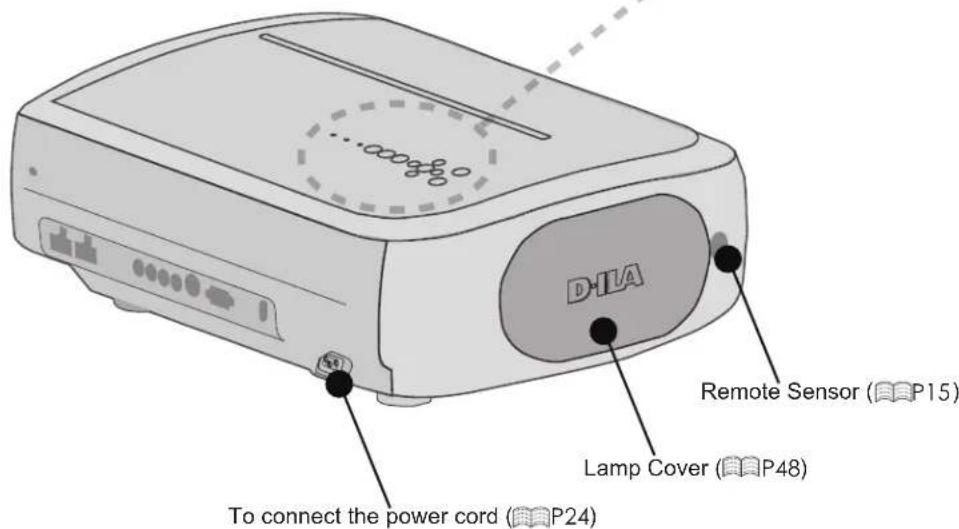
■ Rear Side/Top Side/Right Side
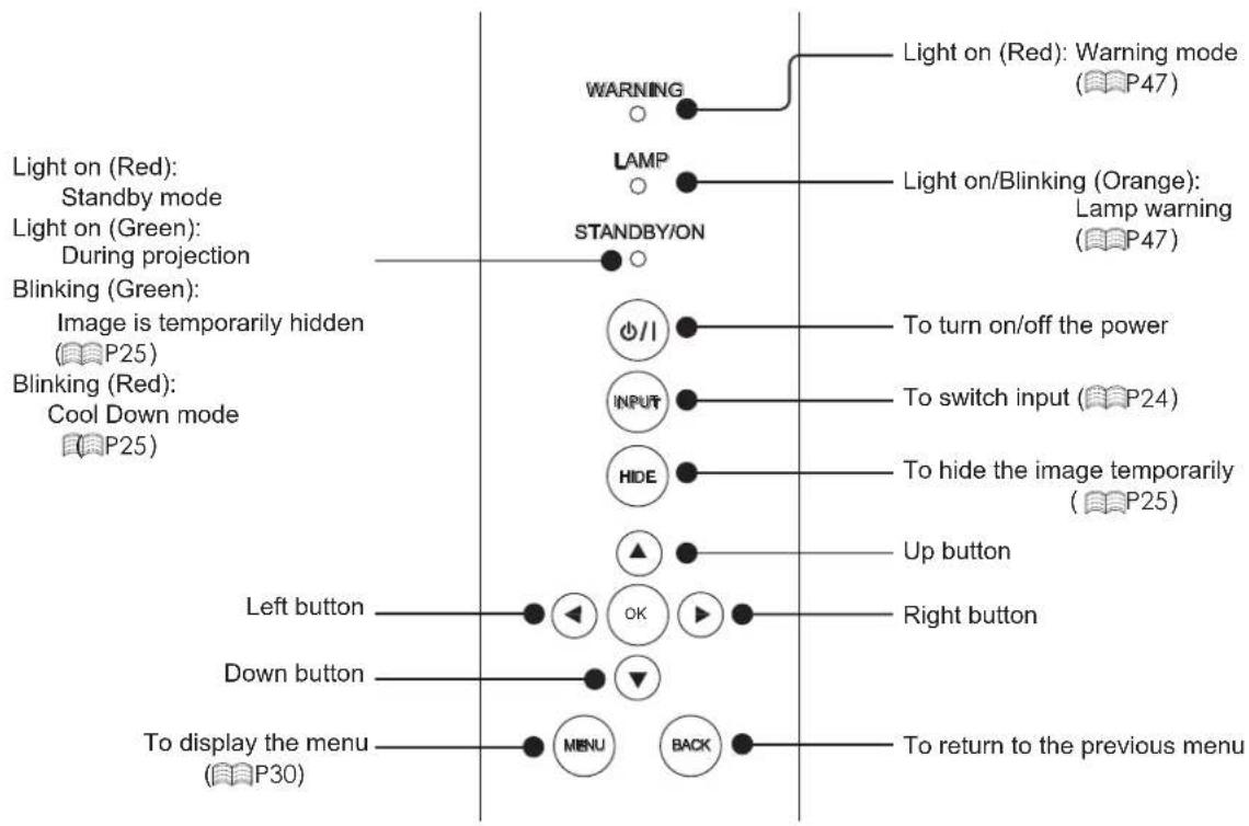
flowchart
graph TD
    A["Light on (Red): Standby mode"] --> B["STANDBY/ON"]
    C["Light on (Green): During projection"] --> B
    D["Blinking (Green): Image is temporarily hidden (P25)"] --> E["O/I"]
    F["Blinking (Red): Cool Down mode (P25)"] --> G["INPUT"]
    H["Left button"] --> I["OK"]
    J["Down button"] --> K["▼"]
    L["To display the menu (P30)"] --> M["MENU"]
    N["To return to the previous menu"] --> O["BACK"]
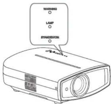
    P["Light on (Red): Warning mode (P47)"] --> Q["Warning"]
    R["Light on/Blinking (Orange): Lamp warning (P47)"] --> S["LAMP"]
    T["To turn on/off the power"] --> U["To switch input (P24)"]
    V["To hide the image temporarily (P25)"] --> W["HIDE"]
    X["Up button"] --> Y["▲"]
    Z["Right button"] --> AA["Right button"]
■ Bottom Surface
Feet: The height (0 to 5 mm) can be adjusted by turning the foot.
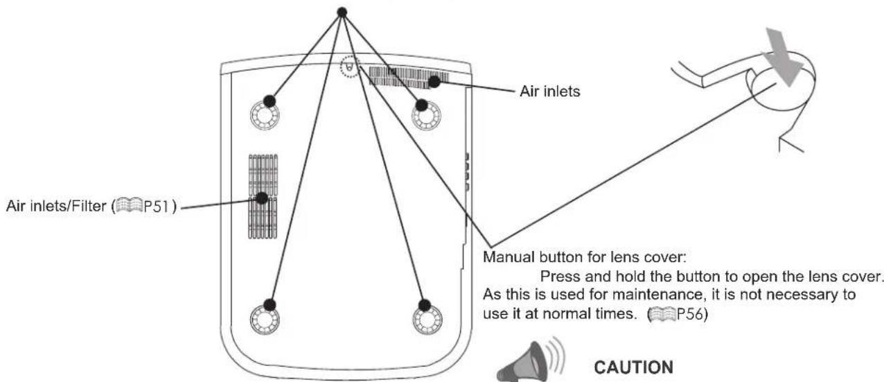

CAUTION
- Do not close lens cover when projecting. Otherwise it will cause malfunction, heat and fire.
Controls and features (continued)
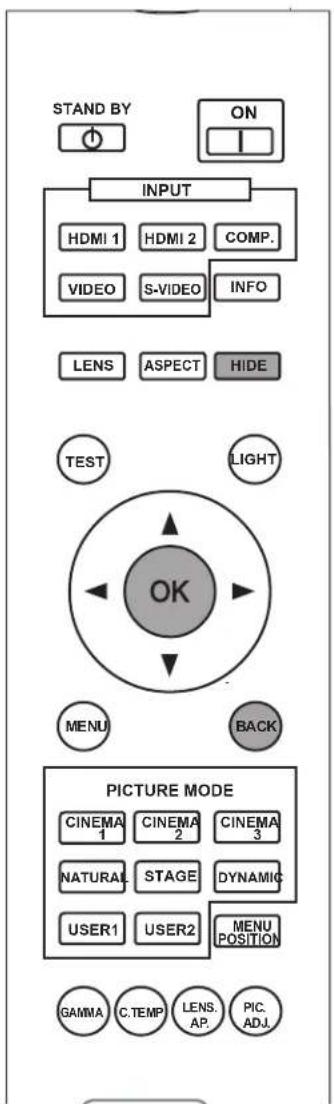
■ Remote Control
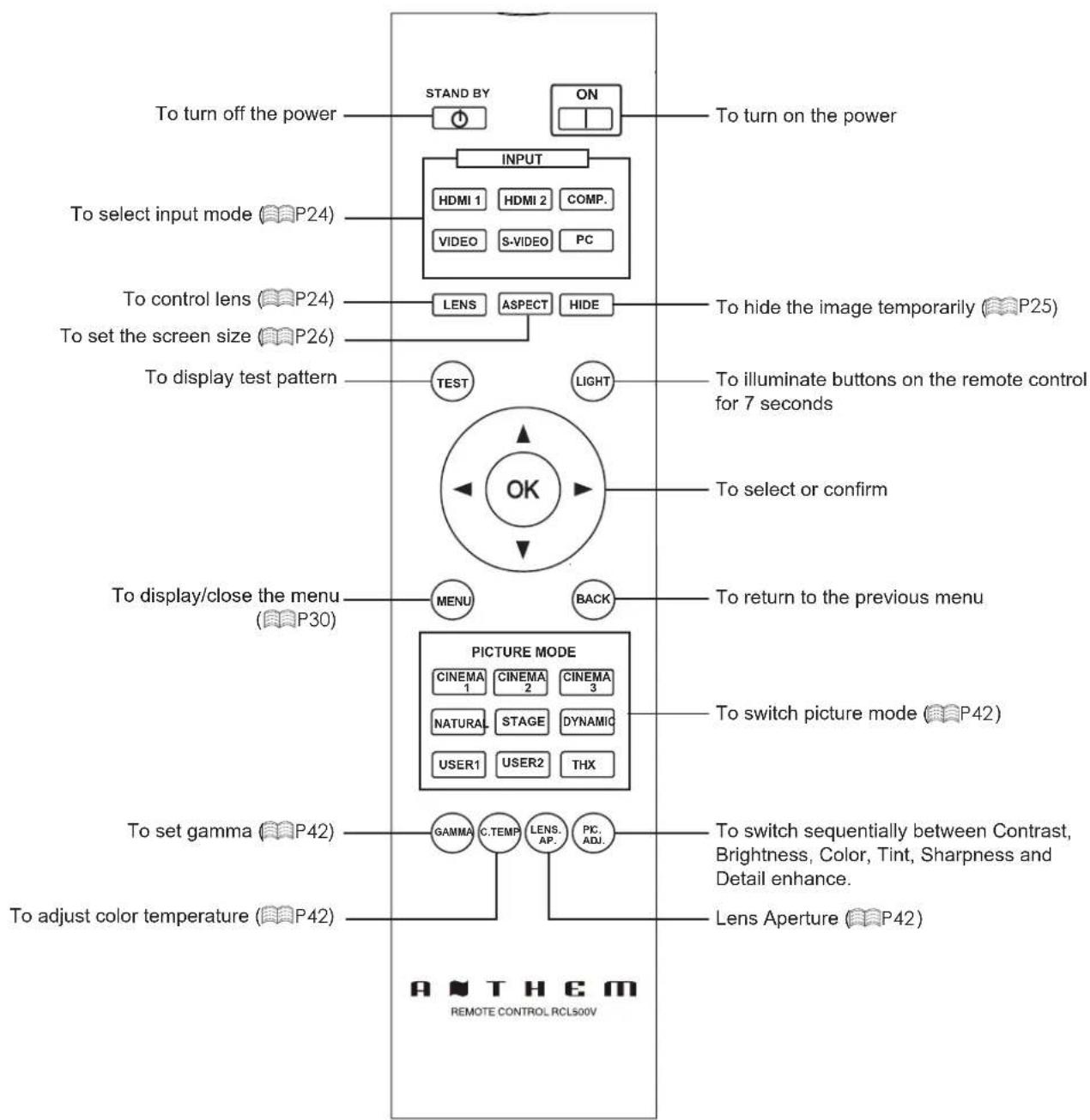
flowchart
graph TD
    A["To turn off the power"] --> B["STAND BY"]
    B --> C["ON"]
    C --> D["To turn on the power"]
    E["INPUT"] --> F["HDMI 1 HDMI 2 COMP."]
    E --> G["VIDEO S-VIDEO PC"]
    H["To select input mode (P24)"] --> I["LENS ASPECT HIDE"]
    J["To control lens (P24)"] --> K["LENS"]
    L["To set the screen size (P26)"] --> M["LENS"]
    N["To display test pattern"] --> O["TEST LIGHT"]
    P["OK"] --> Q["To illuminate buttons on the remote control for 7 seconds"]
    R["TO display/close the menu (P30)"] --> S["MENU BACK"]
    T["PICTURE MODE"] --> U["CINEMA 1 CINEMA 2 CINEMA 3"]
    T --> V["NATURAL STAGE DYNAMIC"]
    T --> W["USER1 USER2 THX"]
    X["To set gamma (P42)"] --> Y["GAMMA C.TEMP LENS AP. PIC ADJ."]
    Z["To adjust color temperature (P42)"] --> AA["Lens Aperture (P42)"]
    AB["To switch sequentially between Contrast, Brightness, Color, Tint, Sharpness and Detail enhance."] --> AC["To switch sequentially between Contrast, Brightness, Color, Tint, Sharpness and Detail enhance."]
    AD["To return to the previous menu"] --> AE["To switch picture mode (P42)"]
How to Use the Remote control
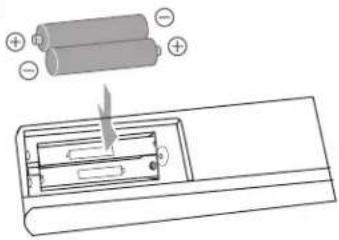
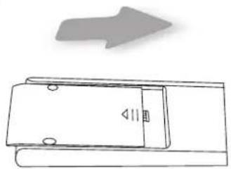
Loading Batteries
①
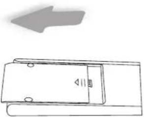
natural_image
Simple line drawing of a door with a speaker and arrow, no text or symbols present②
③
natural_image
Simple line drawing of a door with a handle and arrow indicating direction (no text or symbols)- If the remote control has to be brought closer to the projector to operate, it means that the batteries are wearing out. When this happens, replace the batteries. Insert the batteries according to the + + marks.
- Be sure to insert the Ⓗ end first.
- If an error occurs when using the remote control, remove the batteries and wait for 5 minutes. Load the batteries again and operate the remote control.
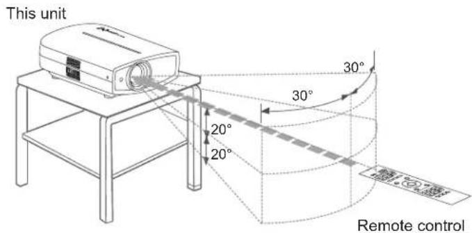
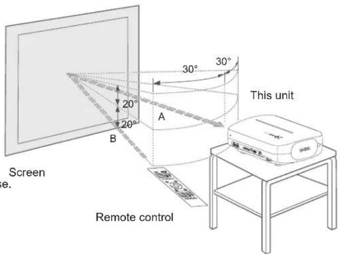
Effective Range of Remote Control Unit
■ When directing the remote control toward this unit
- When aiming the remote control towards the remote sensor on this unit, ensure that the distance to the sensor in front or at the rear of this unit is within 7 m.
- If the remote control fails to work properly, move closer to this unit.
■ When reflecting off a screen
- Ensure that the total of distance A between this unit and screen and distance B between remote control and screen is within 7 m.
- As the efficiency of signals reflected from the remote control unit differ with the type of screen used, operable distance may decrease.
Selecting Connecting Devices
- Do not turn on the power until connection is complete.
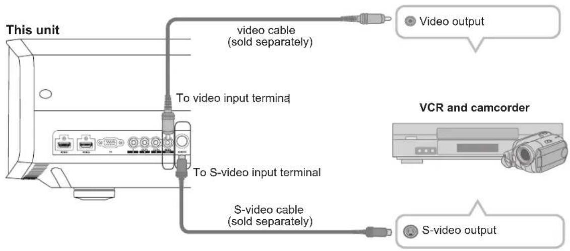
- The connection procedures differ according to the device used. For details, refer to the instruction manual of the device to be connected.
- This device is used for image projection. Connect to an audio output device such as amplifier and speaker for audio output from the connected device.
- The images may not be displayed depending on the devices and cables to be connected. For HDMI cable (sold separately), only use one that is HDMI-approved.
- It may not be possible to connect to this unit depending on the dimension of the connector cover of the cables to be connected.
natural_image
Illustration of desktop computers including a laptop, tower, and monitor (no text or symbols)PC
natural_image
Illustration of a vintage camera with display panel and control buttons (no text or symbols)VCR and camcorder
Connecting
Connecting via Video Cable and S-Video Cable
Connecting via Component Video Cable
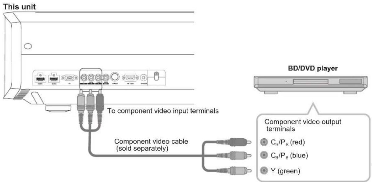
- Set "COMP." in the setting menu to "Y Pb/Cb Pr/Cr". (P36 - 12)
Connecting (continued)
Connecting via HDMI Cable
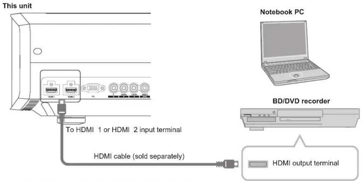
- If noise is produced, take PCs (Notebook PC) away from this unit.
- Use only HDMI-approved equipment.
- Reducing the length of the cable is recommended if there is no picture.
Connecting via HDMI-DVI Conversion Cable
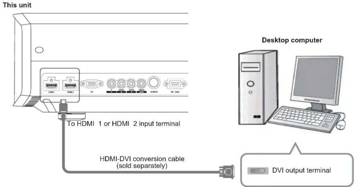
- If noise is produced, take PCs (desktop computer) away from this unit.
- Reducing the length of the cable is recommended if there is no picture.
Connecting via SCART-RCA Cable
This unit
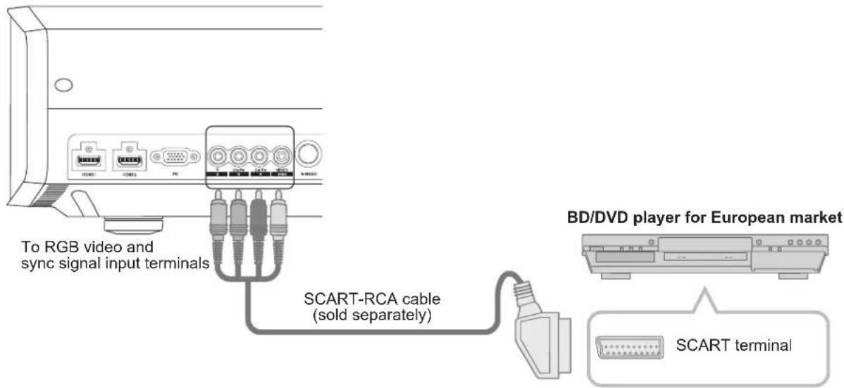
- Set "COMP." in the setting menu to "SCART". (P36 - 12)
Connecting via RGB Video Cable
This unit
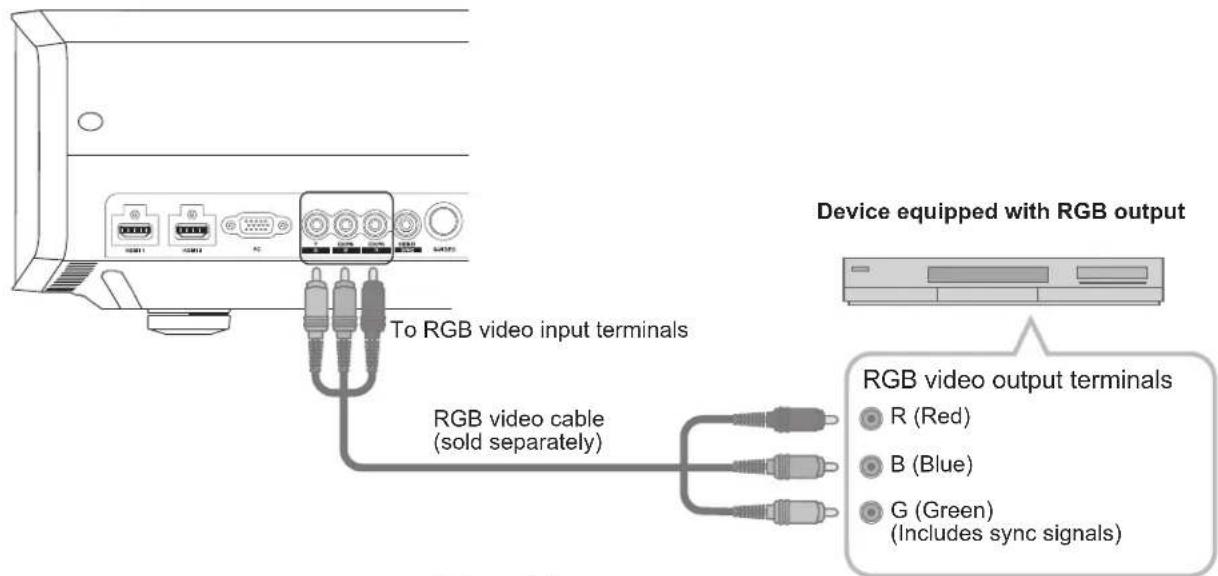
- Set "COMP." in the setting menu to "RGB". (P36 - 12)
- For information on compatible input signals, see "Specifications". (P58)
Connecting (continued)
Connecting via PC Cable
This unit
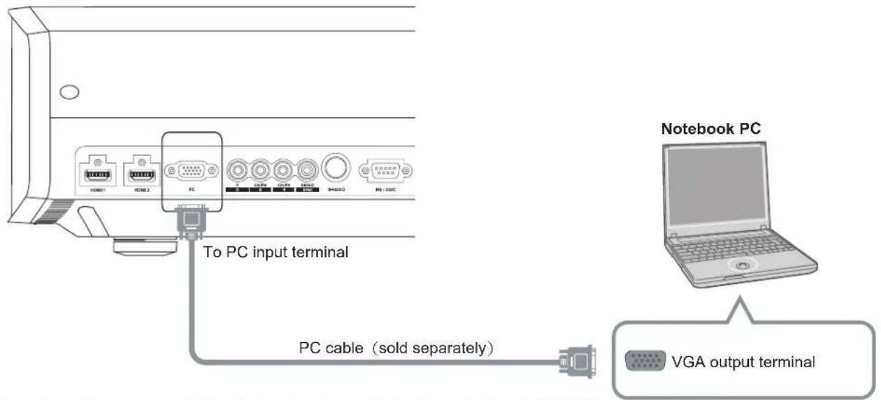
- For information on supported input signals, please refer to "Specifications". (P58)
Connecting via Trigger Cable
This unit
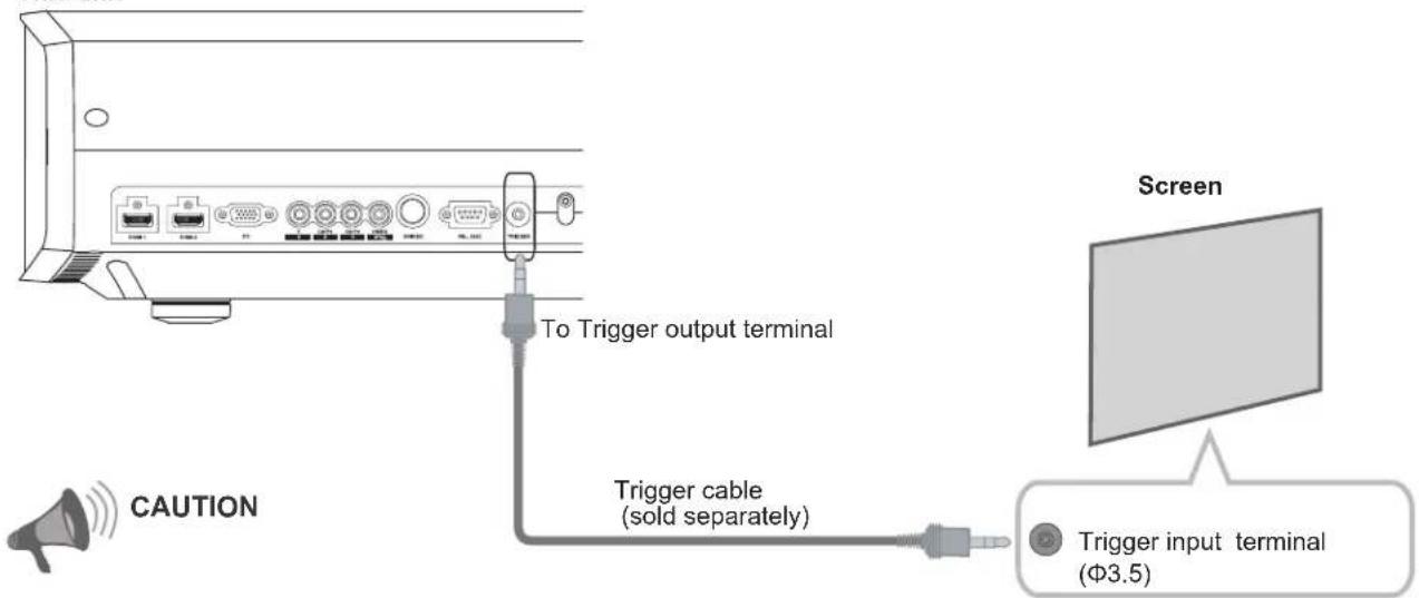
- Do not supply the power to the other devices.
- Do not connect audio terminals of the other devices such as headphones etc. Otherwise, this may cause a malfunction of the other devices or injury.
- Using beyond the rated value will cause malfunction.
- Exercise adequate caution to prevent short circuit as the trigger terminal outputs a voltage of 12V.
Installing the Projector and Screen
While installing, please place this unit and the screen perpendicular to each other. Failing to do so may increase trapezoidal distortion. Please refer to "Keystone". (P39 - 25)
Set Angle
- The angle range which can be set for this unit is ± 10^ .
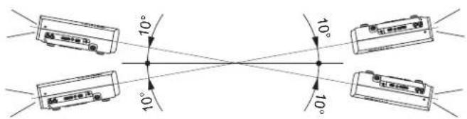
● Malfunctions may occur if the angle is not set within the above-mentioned range.
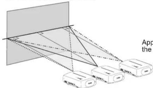
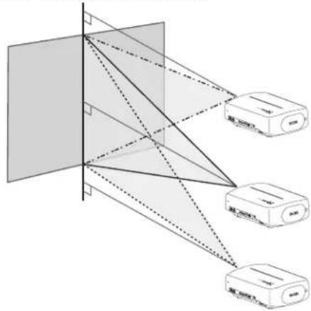
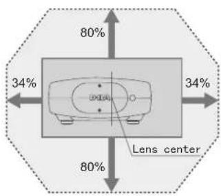
Shift
■ Left/Right position
* 0% up/down position (center)
flowchart
graph TD
    A["App the"] --> B["Device 1"]
    A --> C["Device 2"]
    A --> D["Device 3"]
    B --> E["Application"]
    C --> E
    D --> E
Approximately 34% (maximum) of the projected image
Approximately 34% (maximum) of the projected image
■ Up/Down position
* 0% left/right position (center)
flowchart
graph TD
    A["Input"] --> B["Device 1"]
    A --> C["Device 2"]
    A --> D["Device 3"]
    B --> E["Output"]
    C --> E
    D --> E
Approximately 80% (maximum) of the projected image
Approximately 80% (maximum) of the projected image
Lens shift correlation chart:
| Left-Right Shift (%) 0 | % 5% | 10% | 15% | 20% | 25% | 30% | 34% | |||
| Up-Down Shift (%) 8 | 0% | 74% | 66% | 57% | 47% | 34% | 18% | 0% |
● Maximum Up-Down shift varies with the amount of Left-Right shift. Likewise, maximum Left-Right shift varies with the amount of Up-Down shift.
- The values on the chart are intended to act as a guide. Use them for reference during installation.
■ Shifting range of projected image
Installing the Projector and Screen
(continued)
Screen Size and Projection Distance
Determine the distance from the lens to the screen to achieve your desired screen size.
This unit uses a 2.0x power zoom lens for projection.
■ Relationship Between Projection Screen Size and Projection Distance
| Projection Screen Size (Diagonal Length) Aspect Ratio 16:9 | Approximate Projection Distance W (Wide) to T (Tele) |
| 60" (Approx. 1.52m) | Approx. 1.78m to Approx. 3.66m |
| 70" (Approx. 1.78m) | Approx. 2.09m to Approx. 4.28m |
| 80" (Approx. 2.03m) | Approx. 2.40m to Approx. 4.89m |
| 90" (Approx. 2.29m) | Approx. 2.70m to Approx. 5.51m |
| 100" (Approx. 2.54m) | Approx. 3.01m to Approx. 6.13m |
| 110" (Approx. 2.79m) | Approx. 3.31m to Approx. 6.75m |
| 120" (Approx. 3.05m) | Approx. 3.62m to Approx. 7.36m |
| 130" (Approx. 3.30m) | Approx. 3.92m to Approx. 7.98m |
| Projection Screen Size (Diagonal Length) Aspect Ratio 16:9 | Approximate Projection Distance W (Wide) to T (Tele) |
| 140" (Approx. 3.56m) | Approx. 4.23m to Approx. 8.60m |
| 150" (Approx. 3.81m) | Approx. 4.53m to Approx. 9.22m |
| 160" (Approx. 4.06m) | Approx. 4.84m to Approx. 9.84m |
| 170" (Approx. 4.32m) | Approx. 5.14m to Approx. 10.45m |
| 180" (Approx. 4.57m) | Approx. 5.45m to Approx. 11.07m |
| 190" (Approx. 4.83m) | Approx. 5.75m to Approx. 11.68m |
| 200" (Approx. 5.08m) | Approx. 6.06m to Approx. 12.30m |
- The projection distances in the table are provided only as a guide. Use them as a reference during installation.
- To adjust the installation, use a projected image of aspect ratio 16:9.
MEMO
Projecting Image
This section describes the basic operations to project input images on the screen.
Preparation
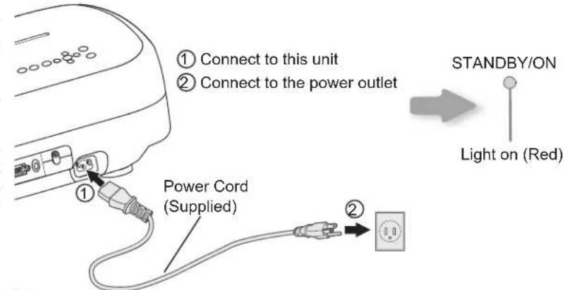
1 Insert the power plug to the power outlet
2 Turn on the power

- You can also press button on the unit to turn on the power. (P13)
● The lens cover will be opened.
3 Project the image
1 Select input mode
- You can also select the input mode by pressing the INPUT button on the unit. (P13)

2 Play back the selected device
4 Adjusts image focus, size (zoom), and position (shift).
1 Adjust the focus
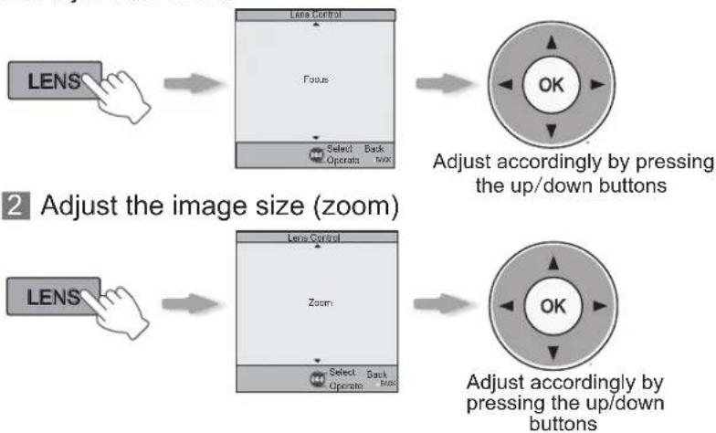
flowchart
graph TD
    A["LENS"] --> B["Lens Control"]
    B --> C["Select Operate"]
    C --> D["Back Top"]
    D --> E["Adjust accordingly by pressing the up/down buttons"]
    F["LENS"] --> G["Lens Control"]
    G --> H["Select Operate"]
    H --> I["Back Top"]
    I --> J["Adjust accordingly by pressing the up/down buttons"]
3 Adjust image position (shift).
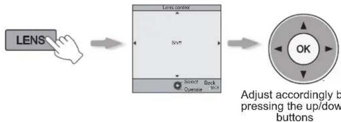
flowchart
graph LR
    A["LENS"] --> B["Shift"]
    B --> C["Select Back"]
    C --> D["Operative Back"]
    D --> E["OK"]
    style A fill:#f9f,stroke:#333
    style E fill:#ccf,stroke:#333
- After adjusting the image position, it may be necessary to select "Pixel Adjust" from the Settings menu "Installation".
- Every time the LENS button is pressed, the adjustment item will be switched among "Focus", "Zoom" and "Shift".

4 To end

5 Turn off the power
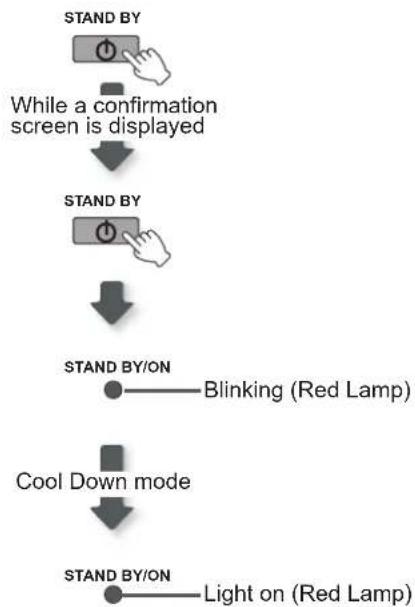
flowchart
graph TD
    A["STAND BY"] --> B["While a confirmation screen is displayed"]
    B --> C["STAND BY"]
    C --> D["STAND BY/ON"]
    D --> E["Blinking (Red Lamp)"]
    D --> F["Cool Down mode"]
    F --> G["STAND BY/ON"]
    G --> H["Light on (Red Lamp)"]
- When power off, the lens cover will be closed.
- The power cannot be turned off within approximately 90 seconds after it has been turned on. Start operation only after 90 seconds time.
- You can also press the button on the unit to turn off the power. (P13)
- Pull out the power plug when the unit will not be used for a prolonged time.

TIPS
You can hide the image temporarily
You can hide the image temporarily.
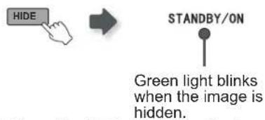
- Press the button again to display image.
● The power cannot be turned off when the image is temporarily hidden.
MEMO
About Cool Down mode
● The Cool Down mode is a function to cool down the lamp for approximately 60 seconds after projection is complete. This function prevents the internal parts of the unit from deformation or damage due to overheating of the lamp. It also prevents lamp blowout and premature shortening of lamp life.
● During Cool Down mode, the [STANDBY/ON] indicator blinks in red.
- After the Cool Down mode is complete, the unit automatically returns to standby mode.
- Do not pull out the power plug during Cool Down mode. This may shorten the lamp life and cause a malfunction.
Convenient Features during Projection
You can change the screen size of the projected image or hide the surrounding area of an image for which quality at the outer area has deteriorated.
Setting the Screen Size
The projected image can be set to a most appropriate screen size (aspect ratio).

- The screen size can also be set from "Aspect (Video)" of the setting menu. (P37 - 16)
- When PC signals are input, the "Aspect (Computer)" setting will be available instead. (P37 - 17)
■ Input Image and Projected Image by Different Screen Size Settings
| Input Image | Screen Size | ||
| 4 : 3 | 16 : 9 | Zoom | |
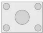 | 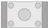 | 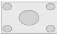 | 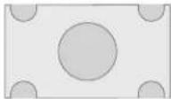 |
| SDTV (4:3) | Aspect Ratio: Same Most appropriate screen size | Aspect Ratio: Landscape Image is stretched horizontally | Aspect Ratio: Same Top and bottom of the image are missing |
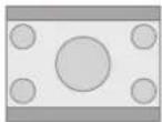 | 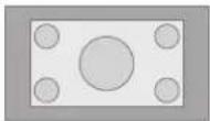 | 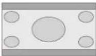 |  |
| SDTV(4:3) Image recorded in landscape (black bands on top and bottom) of DVD software | Aspect Ratio: Same Small image is projected | Aspect Ratio: Landscape Image is stretched horizontally | Aspect Ratio: Same Most appropriate screen size |
- Depending on the input image, selecting "4:3" may result in a vertically stretched image, while selecting "16:9" provides you with the most appropriate screen size.
Masking the Surrounding Area of an Image
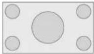
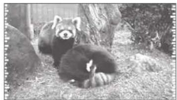
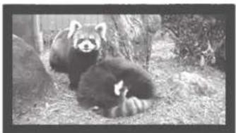
Images for which quality at the outer area has deteriorated can be projected by masking (hiding) the surrounding area of the projected image.
1 Project the image
natural_image
Black-and-white photo of two red-capped pandas resting on grassy ground near a tree (no text or symbols visible)
Image for which quality at the outer area has deteriorated.
2 Mask the image
1 Display the setting menu
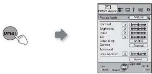
2 Select "Input Signal" → "Mask"
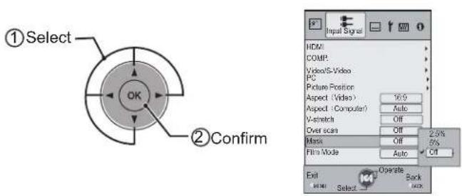
3 Set a mask value
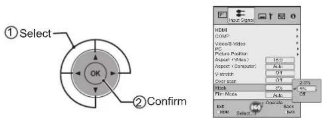
Example:
When the "Mask" value is
changed from "Off" → "5%"
natural_image
Black-and-white photo of a panda resting in a natural setting with trees and straw (no text or symbols visible)3 To end

MEMO
● Masking is available only when high definition images are input.
The structure of the Settings menu
The menu for this device is structured as follows:

CAUTION
- There are items that cannot be modified without entry.
| Picture Adjust | |
| 01 Picture Mode | Adjusts the pattern of the projected image. |
| Setting: Cinema 1, Cinema 2, Cinema 3, Natural, Stage, Dynamic, User 1, User 2, THX | |
| 02 Contrast | Adjusts the contrast of the projected image. |
| Setting: -50 to 50 | |
| 03 Brightness | Adjusts the brightness of the projected image. |
| Setting: -50 to 50 | |
| 04 Color | Adjusts the color density of the projected image. |
| Setting: -50 to 50 | |
| 05 Tint | Adjusts the hue of the projected image. |
| Setting: -50 to 50 | |
| 06 Color Temp. | Sets the color temperature of the projected image. |
| Setting: 5800K, 6500K, 7500K, 9300K, High Bright, Custom 1, Custom 2, Custom 3 | |
| 07 Gamma | Sets the gradation characteristics of the projected image. |
| Setting: Normal, A, B, C, D, Custom 1, Custom 2, Custom 3 | |
| 08 Advanced | Adjusts the contours of the image and detailed composition of the image. |
| Setting: Sharpness, NR, CTI, Color Management, Clear Motion Drive | |
| 09 Lens Aperture | Sets the lens aperture. |
| Setting: -15 to 0 | |
| 10 Reset | Reset the setting. |
| Input Signal | |
| 11 HDMI | Configures HDMI input signal. |
| Setting: Input, Color Space, Control with HDMI | |
| 12 COMP. | Configures the input signal for the component video input terminals. |
| Setting: Y Pb/Cb Pr/Cr, RGB, SCART | |
| 13 Video/S-Video | Configures the Video/S-Video input signals. |
| Setting: NTSC, Setup Level, Color System | |
| 14 PC | Configures PC input. |
| Setting: Auto Alignment, Tracking, Phase, Picture Position | |
| 15 Picture Position | Adjusts the horizontal/vertical position of the projected image. |
| 16 Aspect (Video) | Configures the screen size of the projected image. |
| Setting: 4:3, 16:9, Zoom | |
| 17 Aspect (Computer) | Configures the screen size of the projected image. |
| Setting: Auto, 1:1, Full | |
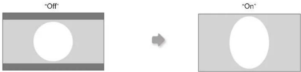
| 18 V-Stretch | When set to “On”, the projected 2.35:1 image will be stretched vertically to the panel resolution. |
| Setting: On, Off | |
| 19 Over Scan | Selects whether or not to set over scan for the SD video signal. |
| Setting: On, Off | |
| 20 Mask | Masks (Hides) the outer area of the projected image. |
| Setting: 2.5, 5, Off | |
| 21 Film Mode | Selects this to view movies shot on film. |
| Setting: Auto, film, Off | |
| Installation | |
| 22 Lens Control | Controls the individual motorized function of the lens when setting up the projector. |
| Setting: Focus, Zoom, shift, Image pattern, Lock | |
| 23 Pixel Adjust | Makes fine adjustments of 1 pixel unit for each minor color shift in the horizontal/vertical direction of the image. |
| Setting: horizontal and vertical | |
| 24 Installation Style | Flips the image to the left or right, up or down according to the projection state of the projector. |
| Setting: Front, Ceiling Mount (F), Rear Ceiling Mount (R) | |
| 25 Keystone | Compensates for trapezoidal distortion caused by installation. |
| 26 Screen Adjust | Corrects skewed white balance derived from the reflective characteristics of the screen. |
| Setting: Off, A, B, C | |
| Display Setup | |
| 27 Back Color | Configures the screen color displayed when there is no input signal. |
| Setting: Blue, Black | |
| 28 Menu Position | Sets the display position of the menu. The possible positions for displaying the menu are at the four corners or at center of the screen. |
| 29 Menu Display | Sets the duration for displaying the menu. |
| Setting: 15sec, On | |
| 30 Line Display | Sets whether to display the input setting when switching the input. |
| Setting: 5 sec, Off | |
| 31 Source Display | Sets whether to display the source of input signals when changing the input. |
| Setting: On, Off | |
| 32 Logo | Sets whether to display “Logo” during startup. |
| Setting: On, Off | |
| 33 Language | Sets the language of the menu display (12 languages). |
| Function | |
| 34 Lamp Power | Configures the output of the light-source lamp. |
| Setting: Normal, High | |
| 35 Trigger | Configures the output of Trigger terminal. |
| Setting: Off, On (Power), On (V-Stretch) | |
| 36 Test Pattern | Display 6 types of test patterns. |
| 37 Off Timer | Automatically powers off when there is no operation for a certain duration. |
| Setting: 1 hour, 2 hours, 3 hours, 4 hours | |
| 38 High Altitude Mode | Selects this when using the projector in a location of low atmospheric pressure (higher than 900 meters above sea level). |
| Setting: On, Off | |
| Information |
| Input Image Connector, Input Source Name, PC resolution, PC H Frequency, PC V Frequency, Deep Color Depth, and Lamp Use are displayed. |
Setting Menu
Projected images can be adjusted to a desired view by changing the initial settings.
Procedures for Menu Operation
Example:
When changing "Aspect (Video)" from "4:3" to "16:9"
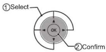
1 Display the setting menu


② Select "Input Signal" → "Aspect (Video)"
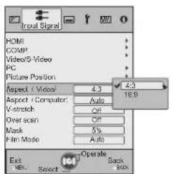
③ Set to “16:9”
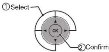
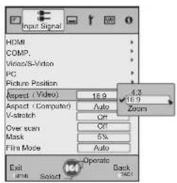
4 To end

Setting Menu
Item values shown in are factory settings.
- Items that can be configured differ according to the input signals.

CAUTION
● There are items that cannot be modified without entry.
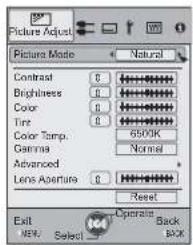
Picture Adjust
| 01 Picture Mode | ||
| Selects Picture Mode(Cinema 1, Cinema 2, Cinema 3, Natural, Stage, Dynamic, User 1, User 2 and THX). | ||
| Cinema 1 | This is the picture setting closest to film. It is best suited for general movie viewing. | |
| Cinema 2 | This is the picture setting for vivid hues based on HDTV standards. It is best suited for viewing action movies and movies with vivid colors. | |
| Cinema 3 This is the picture setting best suited for viewing animated movies. | ||
| Natural This is the picture setting for natural hues and tones. It is best suited for viewing dramas and video. | ||
| Stage This is the picture setting best suited for watching live concerts and stage performances. | ||
| Dynamic | This is the picture setting best suited for viewing the picture in a room that cannot be made completely dark. | |
| THX This is the picture setting certified by THX Ltd. | ||
| 02 Contrast | ||
| Adjusts the contrast of the projected image. | ||
| (Black) -50 to 50 (White) | ||
| 03 Brightness | ||
| Adjusts the brightness of the projected image. | ||
| (Darken) -50 to 50 (Brighten) | ||
| 04 Color | ||
| Adjusts the color density of the projected image. | ||
| (Lighten) -50 to 50 (Darken) | ||
| 05 Tint | ||
| Adjusts the hue of the projected image. | ||
| (Red) -50 to 50 (Green) | ||
Setting Menu (Continued)
| Picture Adjust > Color Temp. | |||
| 06 Color Temp. | |||
| Sets the color temperature of the projected image. (Cannot set when the “Picture Mode” in “THX”).) | |||
| 5800K | Select this to give a reddish tinge to the image. | Only offset can be set. | |
| 6500K Select this to have a balanced image. | |||
| 7500K | Select this to give a bluish tinge to the image. | ||
| 9300K | Select this to give a greater bluish tinge than 7500K. | ||
| High Bright Select this to get the brightest image. | |||
| Custom 1 | Correction Value | Based on this selection of Correction Value (5800K, 6500K, 7500K, 9300K, H.B.), adjusts the following Gains and Offsets. | |
| Gain (Bright part) | Red (Less red) -50 to 50 (More red) | ||
| Green (Less green) -50 to 50 (More green) | |||
| Blue (Less blue) -50 to 50 (More blue) | |||
| Offset (Dark part) | Red (Less red) -50 to 50 (More red) | ||
| Green (Less green) -50 to 50 (More green) | |||
| Blue (Less blue) -50 to 50 (More blue) | |||
| Custom 2 | Correction Value | Based on this selection of Correction Value (5800K, 6500K, 7500K, 9300K, H.B.), adjusts the following Gains and Offsets. | |
| Gain (Bright part) | Red (Less red) -50 to 50 (More red) | ||
| Green (Less green) -50 to 50 (More green)) | |||
| Blue (Less blue) -50 to 50 (More blue) | |||
| Offset (Dark part) | Red (Less red) -50 to 50 (More red) | ||
| Green (Less green) -50 to 50 (More green) | |||
| Blue (Less blue) -50 to 50 (More blue) | |||
| Custom 3 | Correction Value | Based on this selection of Correction Value (5800K, 6500K, 7500K, 9300K, H.B.), adjusts the following Gains and Offsets. | |
| Gain (Bright part) | Red (Less red) -50 to 50 (More red) | ||
| Green (Less green) -50 to 50 (More green ) | |||
| Blue (Less blue) -50 to 50 (More blue) | |||
| Offset (Dark part) | Red (Less red) -50 to 50 (More red) | ||
| Green (Less green) -50 to 50 (More green) | |||
| Blue (Less blue) -50 to 50 (More blue) | |||
● The red, green and blue colors can be adjusted and registered respectively.
- This setting can also be configured from the remote control. (P14)
| Picture Adjust > Gamma | |||
| 07 Gamma | |||
| Sets the gradation characteristics of the projected image. (Cannot set when the "Picture Mode" in "THX".) | |||
| Normal | For normal circumstances, select this setting. | This is the setting for Standard Tones. | |
| A Set gamma to | "A". | This is the setting for expressing rich dark tones. | |
| B Set gamma to | "B". | This is the setting for the characteristic tonal qualities of film. | |
| C Set gamma to | "C". | This setting provides even richer darker tones than setting B. | |
| D Set gamma to | "D". This setting provides brighter midtones. | ||
| Custom 1Custom 2Custom 3(Gamma Setup) | Three different kinds of gamma can be set according to your preferences. | ||
| Correction Value | The coefficient (1.8 to 2.6) of the gamma curve can be selected. | ||
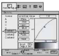
| Gamma Adjustment* | The gamma curve for the colors (Red, Green, Blue) can be adjusted separately.Adjusting "White" will adjust for all "Red, Green, Blue" values. The gamma curve displays the value for "Green". | ||
| Copy Copy | the adjusted gamma data. | ||
| Paste Paste | the copied gamma data. | ||
| Reset | Return the gamma coefficients to the values 2.2 set by "Correction Value". | ||
- “Normal” is suitable for normal circumstances but other settings can be selected according to your preferences.
- This setting can also be configured from the remote control. (P14)
* "Gamma Adjustment"
① Select the reference gamma curve coefficient (1.8 \~ 2.6) in "Correction Value".
② Select the color to be adjusted in the gamma adjustment screen.
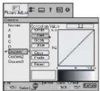
③ Adjust the gamma curve in the gamma curve adjustment screen.
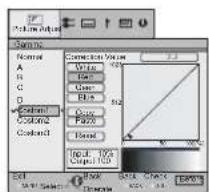
Select the point where the gradation (brightness) is to be adjusted with the ◀/▶buttons.
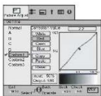
Adjust the gradation (brightness) with the ▲ / ▼ buttons.
- You can switch between "Before" and "After" using the [TEST] button of the remote control.
④ To end

flowchart
graph LR
    A["Start"] --> B["Hand Click"]
    B --> C["BACKBACK"]
    C --> D["Save gamma data?"]
    D --> E["OK"]
    E --> F["Close"]
- If gamma curve is adjusted repeatedly, calculation errors will be accumulated and the gamma curve may not be able to revert back to its original form. In that case, select "Reset".
Setting Menu (continued)
* Regarding "Copy" and "Paste"
① Copies the Gamma Adjustment data.
Select copy using the ▲ buttons.
② Pastes the copied data.

flowchart
graph LR
    A["Drawing Display"] --> B["Paste gamma data?"]
    B --> C{OK}
    C --> D["Resulting Gamma Data"]
Select Paste using the ◀/ ▶ and /▲ buttons.
● Gamma Adjustment data can be copied in all modes, but it is only possible to paste in Custom 1, Custom 2, and Custom 3.
| Picture Adjust | |||||
| 08 Advanced | |||||
| Adjusts the contours of the image, detailed composition of the image and image color. (Cannot set when the "Picture Mode" in "THX".) | |||||
| Sharpness | Sharpness (Soft) 0 to 100 (Sharp) Adjusts the outline of image. | ||||
| Detail Enhancement | (Soft) -50 to 50 (Strong) Emphasizes the details of image. | ||||
| NR* | RNR (Soft) 0 to 16 (Strong) | Adjusts the intensity of removing image noise. | |||
| MNR (Soft) 0 to 16 (Strong) | Adjusts the intensity of removing mosquito noise. | ||||
| BNR | On Reduces block noise. | ||||
| Off Input signal remains unchanged. | |||||
| CTI* | Off Input signal remains unchanged. | ||||
| Low | Reduces color smear. (Color Contour Correction) | ||||
| Middle | |||||
| High | |||||
| * In case of HD signals or PC signals, NR and CTI cannot be set.● AbbreviationsNR: Noise Reduction RNR: Random Noise Reduction MNR: Mosquito Noise ReductionBNR: Block Noise Reduction CTI: Color Transient Improvement | |||||
| Color Management* | Off | The image color cannot be adjusted. | |||
| Custom 1Custom 2Custom 3 | Pause | Off | Video mode | ||
| On | Still mode | ||||
| Color Management Adjustment* | Values of each color can be adjusted ("Red, Yellow, Green, Cyan, Blue and Magenta"). | ||||
| All Reset | Return to the factory settings. | ||||
| Clear Motion Drive* | Off | Improves fast-moving pictures to a clear image with little residual image. | |||
| Low | |||||
| High | |||||
| * With regard to "Clear Motion Drive", it is not possible to set the PC signal. Furthermore, depending on the scene, the picture may be distorted. In this case, please select "off". | |||||
* About "Color Management Adjustment"
① Set the picture mode of the color management.
② Select the color to be adjusted by color management.
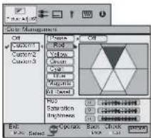
③ Select color adjustment.
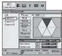
④ Select the "Hue", "Saturation" or "Brightness" using the ▲ / ▼ button.
⑤ Use the ◀ / ▶ button to adjust.

- You can switch between "Before" and "After" using the [TEST] button of the remote control.
⑥ To end

flowchart
graph LR
    A["BACK"] --> B["BACK"]
    B --> C["BACK"]
    C --> D["Save Color Management?"]
    D --> E["OK"]
    style A fill:#fff,stroke:#000
    style B fill:#fff,stroke:#000
    style C fill:#fff,stroke:#000
    style D fill:#fff,stroke:#000
    style E fill:#fff,stroke:#000
- After selecting "Cinema 1", "Cinema 2", or "Cinema 3" from "Picture Mode", and after adjusting "Advanced", adjustment of brightness in each "Color Management" mode is not possible.
Picture Adjust > Lens Aperture
| 09 Lens Aperture | |
| (Dark) -15 to 0 (Bright) | |
| 10 Reset | |
| Reset the setting. | |
Input Signal > HDMI
| 11 HDMI | |||
| Configures HDMI input signal. | |||
| Input | Auto Automatically configu | es the input signals. | |
| Standard | Select this when the dynamic range of the input images is 16-235. | ||
| Enhanced | Select this when the dynamic range of the input images is 0-255. | ||
| Color Space | Auto Automatically configu | es the input signals. | |
| Y Cb Cr (4:4:4) | Select this when the Y Cb Cr (4:4:4) video signals are input. | ||
| Y Cb Cr (4:2:2) | Select this when the Y Cb Cr (4:2:2) video signals are input. | ||
| RGB Select this when the R | RGB video signals are input. | ||
| Control with HDMI | On Enables CEC communications. | ||
| Off Disables CEC communications. | |||
- The setting is available only if the HDMI terminal is selected.
- For some source devices, "Auto (input)" will not function properly. In such cases, please use Standard Mode or Enhanced Mode.
- Abbreviation CEC: Consumer Electronics Control
Setting Menu (continued)
Input Signal > COMP.
| 12 COMP. | |||
| Configures the input signal for the component video input terminals. | |||
| Color Space | Y Pb/Cb Pr/Cr Select this when the component video signals are input. | ||
| RGB Select this when the RGB video signals are input. | |||
| SCART | Select this when RGB video signals and sync signals are input via the SCART interface for European markets. | ||
- The setting is available only if the component video terminals are selected.
Input Signal > Video/S-Video
| 13 Video/S-Video | |||
| Configures the Video/S-Video input signals. | |||
| NTSC Setup Level | 0IRE Adjusts the gradation | for signals without the 7.5 IRE setup. | |
| 7.5IRE Adjusts the gradation | for signals with the 7.5 IRE setup. | ||
| ● Adjust this only when NTSC signals are input via Video or S-Video terminal. | |||
| Color System | Auto Configures the color system automatically. | ||
| NTSC Select this when the color system is NTSC. | |||
| NTSC4.43 Select this when the color system is NTSC4.43. | |||
| PAL Select this when the color system is PAL. | |||
| PAL-M Select this when the color system is PAL-M. | |||
| PAL-N Select this when the color system is PAL-N. | |||
| SECAM Select this when the color system is SECAM. | |||
● The setting is available only when the Video or S-Video input image is projected.
Input Signal > PC
| 14 PC | ||
| Configures PC input. | ||
| Auto Alignment Automatically | adjusts “Tracking”, “Phase” and “Picture Position”. | |
| Tracking | Adjust the horizontal size and display area of the image.(This may vary depending on the signal, but does not usually require adjustment.) | |
| Phase | Adjust flickering and blurred images.(This may vary depending on the signal, but does not usually require adjustment.) | |
| Picture Position Adjust the display position of the image. | ||
- This can be set only when selecting PC input terminal.
Input Signal > Picture Position
| 15 Picture Position |
| Adjusts the horizontal/vertical position of the projected image. |
- The position of the image varies depending on the input signals. The image of some signals may not be fully displayed. Adjust the position of image using this menu to display the image properly.
Input Signal > Aspect (Video)
| 16 Aspect (Video) | ||
| Configures the screen size of the projected image. | ||
| 4:3 Sets the screen size of the projected image as 4:3. | ||
| 16:9 Sets the screen size of the projected image as 16:9. | ||
| Zoom Zooms the images. (This item cannot be selected in the case of HD signals.) | ||
- This setting can also be configured from the remote control. (P14)
● The items cannot be set in the case of PC signals.
Input Signal > Aspect (Computer)
| 17 Aspect (Computer) | ||
| Configures the screen size of the projected image. | ||
| Auto | Enlarges the PC signal horizontally/vertically until it fits the panel height, and displays it in the original aspect ratio. | |
| 1:1 | Displays the PC signal corresponding to the panel at one dot per pixel ratio. The PC screen can be shown in the original size. | |
| Full Enlarges the PC signal horizontally/vertically. | ||
- This setting can also be configured from the remote control. (P14)
● This setting cannot be set in the case of SD or HD signals.
Input Signal > V-Stretch (when HD or SD video signals are input)
| 18 V-Stretch | ||
| When set to “On”, the projected 2.35:1 image will be stretched vertically to the panel resolution. | ||
| On The projected 2.35:1 image | will be stretched vertically to the panel resolution. | |
| Off Projects the 2.35:1 image as-is. (Black bands will be displayed on the top and bottom.) | ||
● This setting cannot be set in the case of PC signals.
Input Signal > Over Scan
| 19 Over Scan | ||
| Selects whether or not to set over scan for the SD video signal. | ||
| On Over scan the top, left, bottom and right at 2.5% each. | ||
| Off Do not over scan. | ||
● This setting is not available when HD signal or PC signal is input.
Setting Menu (continued)
Input Signal > Mask
| 20 Mask | ||
| Masks (Hides) the outer area of the projected image. | ||
| 2.5% Mask 2.5% of the screen. | ||
| 5% Mask 5% of the screen. | ||
| Off No masking. | ||
● Masking is available only when high definition images are input.
Input Signal > Film Mode
| 21 Film Mode | ||
| Selects this to view movies shot on film. | ||
| Auto | After determining if the picture is 24 frame film or 60 frames (50 frames) video, changes the setting to the optimal progressive conversion. | |
| Film | Corrects unnatural movement of material pulldown processed from 24 frames to 60 frames (50 frames) and returned to 24 frames. | |
| Off Sets the appropriate progressive conversion for video. | ||
- Only 480i/576i/1080i may be selected.
- Select "Auto" or "Off" if it begins to function improperly. Particularly, with video it does not operate properly.
Installation > Lens Control
| 22 Lens Control | |||
| Controls the individual motorized function of the lens when setting up the projector | |||
| Focus Function for adjusting the lens focus. | |||
| Zoom Function for adjusting the lens zoom. | |||
| Shift | Function for adjusting lens shift. (Press the up/down/left/right button to shift the screen). | ||
| Image Pattern | |||
| On | Displays the image pattern in conjunction with the above setting items. | ||
Display Display for 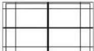 "Focus": "Focus": 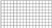 (Picture of big green grids) (Picture of small green grids) (Picture of big green grids) (Picture of small green grids) | |||
| Off Without displaying the image pattern, displays the external input signal. | |||
| Lock | |||
| On | Disables lens adjustment.A warning message appears when the [LENS] button on the remote control is pressed. | ||
| Off Enables lens adjustment. | |||
Installation > Pixel Adjust
| 23 Pixel Adjust | ||
| Makes fine adjustments of 1 pixel unit for each minor color shift in the horizontal/vertical direction of the image. | ||
| Horiz. Red (Move red to left) 1 | to 7 (Move red to right) | |
| Horiz. Green (Move green to left) 1 to 7 (Move green to right) | ||
| Horiz. Blue (Move blue to left) 1 to 7 (Move blue to right) | ||
| Vert. Red (Move red down) 1 to 5 (Move red up) | ||
| Vert. Green (Move green down) 1 to 5 (Moves green up) | ||
| Vert. Blue (Move blue down) 1 to 5 (Move blue up) | ||
- The horizontal and vertical directions are reversed when the image is flipped to the left or right, or flipped up or down.
● To adjust, use still images with distinct outlines. - As the adjustments are minor, the effect may be difficult to see for some images.
Installation > Installation Style
24 Installation Style
Flips the image to the left or right, up or down according to the projection state of the projector.
Front Select this for tabletop front projection.
Ceiling Mount (F) Select this for ceiling front projection.
Rear Select this for tabletop rear projection.
Ceiling Mount (R) Select this for ceiling rear projection.
Installation > Keystone
25 Keystone
Compensates for trapezoidal distortion caused by installation.
- If the "Shift Adjustment" is excepting 0%, the image may be projected on the screen incorrectly when trapezoidal distortion is compensated. (P21)
Installation > Screen Adjust
26 Screen Adjust
Corrects skewed white balance derived from the reflective characteristics of the screen.
Off Makes no correction. (Normally set to "off")
A Corrects to slightly reddish.
B Corrects to slightly greenish.
C Corrects to slightly bluish.
Display Setup > Back Color
27 Back Color
Configures the screen color displayed when there is no input signal.
Blue Sets screen color to "Blue".
Black Sets screen color to "Black".
Display Setup > Menu Position
28 Menu Position
Sets the display position of the menu. The possible positions for displaying the menu are at the four corners or at center of the screen.

Display Setup > Menu Display
29 Menu Display
Sets the duration for displaying the menu.
15 sec Display for 15 seconds.
On Always display.
Setting Menu (continued)
Display Setup > Line Display
| 30 Line Display | ||
| Sets whether to display the input setting when switching the input. | ||
| 5 sec Display for 5 seconds. | ||
| Off Do not display. | ||
Display Setup > Source Display
| 31 Source Display | ||
| Sets whether to display the source of input signals when changing the input. | ||
| On Display the source of input signals. | ||
| Off Do not display. | ||
Display Setup > Logo
| 32 Logo | ||
| Sets whether to display “Logo” during startup. | ||
| On Display for 5 seconds. | ||
| Off Do not display. | ||
Display Setup > Language
| 33 Language | ||
| Sets the language of the menu display. | ||
| 日本語 | Japanese | |
| English English | ||
| Deutsch German | ||
| Español Spanish | ||
| Italiano Italian | ||
| Français French | ||
| Português Portuguese | ||
| Nederlands Dutch | ||
| Svenska Swedish | ||
| Norsk Norwegian | ||
| Русский Russian | ||
| 中文 | Chinese | |
Function > Lamp Power
| 34 Lamp Power | ||
| Configures the output of the light-source lamp. | ||
| Normal For normal circumstances, select this setting. (150W) | ||
| High | Select this when it is difficult to see the image in a bright room. (200W) | |
- The setting cannot be changed within approximately 90 seconds after this unit has been turned on.
- Settings cannot be changed within approximately 60 seconds after they are made.
Function > Trigger
| 35 Trigger | ||
| Configures the output of Trigger terminal. | ||
| Off Do not activate. | ||
| On (Power) Move the screen UP/DOWN in conjunction with the power. | ||
| On (V-Stretch) Operate the anamorphic lens in conjunction with the “V-Stretch”. | ||
Function > Test Pattern
| 36 Test Pattern |
| Display 6 types of test patterns. For checking the color condition and tone, and the pixel size. Use whenever necessary. |
● This can also be displayed by the remote control. (P14)
Function > Off Timer
| 37 Off Timer | ||
| Automatically powers off when there is no operation for a certain duration. | ||
| Off Disables the off timer. | ||
| 1 hour Auto power off after 1 hour. | ||
| 2 hours Auto power off after 2 hours. | ||
| 3 hours Auto power off after 3 hours. | ||
| 4 hours Auto power off after 4 hours. | ||
Function > High Altitude Mode
| 38 High Altitude Mode | ||
| Selects this when using the projector in a location of low atmospheric pressure (higher than 900 meters above sea level). | ||
| On Enable. | ||
| Off Disable. | ||
Information
| Input Displays the currently selected video input. | ||
| Source | Displays the type of the current video input signal.(If PC signal is input, this item cannot be displayed) | |
| Resolution In the case of PC signal, the resolution is displayed. | ||
| H Frequency In the case of PC signal, the horizontal frequency is displayed. | ||
| V Frequency In the case of PC signal, the vertical frequency is displayed. | ||
| Deep Color | Displays the bit depth (color depth) of the video signals input from the HDMI terminals.[Deep Color is not displayed when Y Cb Cr (4:2:2) is input.] | |
| Lamp Time Displays the accumulated hours of usage of the light-source lamp. | ||
Customizing Projected Images
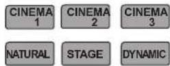
You can adjust the projected image to a desired image quality and register the adjusted value. (Picture Mode) Besides the five default "Cinema 1", "Cinema 2", "Cinema 3", "Natural", "Stage", "Dynamic" and "THX" settings, there are 2 more types of user-defined settings for Picture Mode.
Changing the Initial Setting of Picture Mode
"Contrast", "Brightness", "Color", "Tint", "Color Temp.", "Gamma", "Sharpness", "NR", "CTI", "Lens aperture" and "Clear Motion Drive" are registered in the Picture Mode.
1 Select picture mode
2 Adjust picture quality
Example: To adjust "Contrast"
1 Display the setting menu

2 Select "Picture Adjust"→ "Contrast"
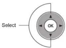
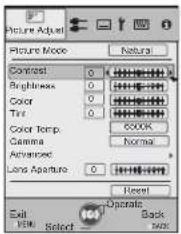
3 Adjust the setting
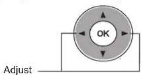

4 To end the adjustments

3 Other items can also be adjusted
4 To end

- "Color Temp.", "Gamma", and "Lens aperture" can also be adjusted from the remote control. (P14)
Registering User-defined Picture Mode
1 Select the picture mode
USER 1
USER 2
2 Adjust picture quality
- See "Changing the initial setting of picture Mode" for procedures on adjusting the picture quality. (P42)
3 To end

Registering User-defined Picture Mode from the Menu
1 Adjust picture quality
- See "Changing the Initial Setting of Picture Mode" for procedures on adjusting the picture quality. (P42)
2 Display the setting menu

③ Select “Picture Adjust” → “Picture Mode” → “Natural”
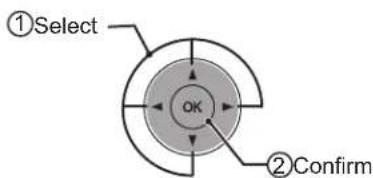
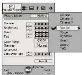
4 Register the setting


CAUTION
- Adjustment settings of image quality will not be registered if other picture mode is selected before registering these settings.
Troubleshooting
Before sending the unit to your authorized dealer for repair, please check the following points.
The following situations are not malfunctions.
■ You do not need to worry about the following situations if there is no abnormality on the screen.
● Part of the top surface or front of the unit is hot.
- A creaking sound is heard from the unit.
- An operating sound is heard from the inside of the unit.
● Color smear occurs on some screens.
■ Perform the following operations when the unit is unable to operate normally due to external static or noise.
① When the unit is in standby mode, please pull out the power plug, then insert again.
② Press the power button on the unit to turn on the power again.
■ A sound may be heard when the lamp is off but there is no danger.
■ D-ILA device is manufactured using high-precision technology but there may be some missing pixels or pixels that remain permanently lit up.
| Power is not supplied | ||
| Is the power cord disconnected? | Insert the power cord (plug) firmly. | P24 |
| Is the lamp cover properly shut? | Remove the power plug when the unit is in standby mode and close the lamp cover properly. After that, insert the plug again. | P49 |
| Is the lamp in Cool Down mode? | After the Cool Down mode is complete, turn on the power again. | P25 |
| Projected image is dark | ||
| Is the lamp near exhaustion? | Check the lamp time on the information menu. Prepare a new lamp unit or replace as soon as possible when the lamp is near exhaustion. | P48 to 50 |
| The unit works when power is turned on but stops abruptly after a few minutes | ||
| Are the air inlets and exhaust vent blocked? | Remove the power plug when the unit is in standby mode and remove any blocking object. After that, insert the plug again. | P12 to 13 |
| Is the filter dirty? | Clean the filter. | P51 |
| Video image does not appear | ||
| Is the correct external input selected? | Select the correct external input. | P24 |
| Is the AV device properly connected? | Connect the AV device properly. | P16 to 20 |
| Is the power of the AV device turned on? | Turn on the power of the AV device and play the video. | P24 |
| Are the correct signals being output from the AV device? | Set the AV device properly. | P16 to 20 |
| Is the setting of the input terminal correct? | Set “COMP.” and “HDMI” in the setting menu according to the input signal. | P35 - 11P36 - 12 |
| Is the video image temporarily hidden? | Press the [HIDE] button to display the video image again. | P25 |
- Even if the "Control with HDMI" function is "On", there are still some devices cannot reveal image normally.
| The picture cannot be projected | ||
| Will the picture flicker and become invisible with HDMI input? | Please use a short HDMI cable. | P18 |
| The image cannot output by HDMI terminal | ||
| Is the setup of “Control with HDMI” function “Off”? | Set up the “Control with HDMI” function to “Off”. | P35 - 11 |
| Color does not appear or looks strange | ||
| Is the image correctly adjusted? | Adjust "Color" and "Tint" in the setting menu. | P31 - 04 05 |
| Video image is fuzzy | ||
| Is the focus correctly adjusted? Adjust the focus. | P24 | |
| Is the unit placed too near or too far away from the screen? | Set the unit at a correct distance from the screen. | P21 to 22 |
| Video images are missing | ||
| Has setting been performed for screen mask? | Set “Mask” in the setting menu to “Off”. | P27, 38 - 20 |
| Is the display out of position? | Alter the “Picture Position” value in the setting menu to ensure that images are not missing. | P36 - 15 |
| Remote control does not work | ||
| Are batteries installed correctly? | Match the polarities (☑r ) ☑rectly when inserting the batteries. | ☑P15 |
| Are batteries exhausted? | Replace with new batteries. | ☑P15 |
| Is there an obstructive object between the remote control and remote sensor? | Remove any obstructive objects. | ☑P15 |
| Is the remote control held too far away from the unit? | Hold the remote control closer to the sensor when using. | ☑P15 |
| Power is cut off suddenly | ||
| Has setting been performed for off timer? | Set "Off Timer" in the setting menu to "Off". | P41 - 37 |
What to Do When these Messages Are Displayed
| Message Cause (Details) | |
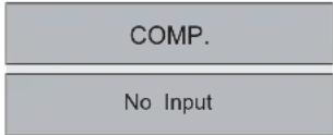 | No device is connected to the input terminal.The input terminal is connected but there is no signal.→Input the video signals. |
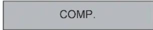 | A video signal that cannot be used in this unit has been input.→Input video signals that can be used.* The names of input terminals such as COMP. will be displayed in yellow. |
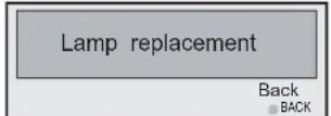 | This message is displayed when the accumulated lamp time has exceeded 2900 hours.To clear the message, press the [Back] button.→Get ready a new lamp unit and replace as soon as possible. Reset the lamp time after replacing the lamp. (P48 to 50) |
About Warning Indicators
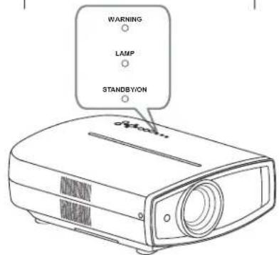
The accumulated lamp time or warning mode of this unit is displayed by the indicators.
For information on indicator display during normal operation, "Controls and Features" (P12)
| No. | Indicator | Blinking Time | Blinking Frequency | Interval between Blinks | Content | |||
| WARNING | LAMP STANDBY /ON | |||||||
| 1 | - | - | Light on (Red) | --- | During standby | Indicator display in normal conditions. | ||
| 2 | - | - | Light on (Green) | --- | When the power on (Hide Off) | |||
| 3 | - | - | Blinking (Green) | 0.5 second | continuous | - | When the power on (Hide On) | |
| 4 | - | - | Blinking (Red) | 0.5 second | continuous | - | During cool down | |
| 5 | - | Light on (orange) | ---- | Lamp replacement is near (P48 to 50)(When accumulated lamp time has exceeded 2900 hours) | ||||
| 6 | - | Light on (orange) | ---- | Lamp has reached the end of life(P48 to 50)(When accumulated lamp time has exceeded 3000 hours) | ||||
| 7 | Light on (Red) | Blinking (orange) | - | 0.25 second | 1 time | 0.75 second | Lamp does not light up and unit is unable to project | |
| 8 | 0.25 second | 2 times | 0.75 second | Lamp is turned off during projection | ||||
| 9 | 0.25 second | 3 times | 0.75 second | Lamp cover is removed | ||||
| 10 | Blinking (Red) | - | - | 0.25 second | 1 time | 0.75 second | Abnormalities in the power supply | |
| 11 | 0.25 second | 2 times | 0.75 second | Cooling fan stops(cooling fan gets caught) | ||||
| 12 | 0.25 second | 3 times | 0.75 second | Internal temperature is too high(abnormal internal temperature) | ||||
| 13 | 0.25 second | 4 times | 0.75 second | External temperature is too high(abnormal external temperature) | ||||
| 14 | Blinking (orange) | 0.25 second | 1 time | 0.75 second | Abnormal electrical circuit(abnormal startup of drive circuit) | |||
| 15 | 0.25 second | 2 times | 0.75 second | Abnormal electrical circuit(abnormal communication of the drive circuit) | ||||
| 16 | 0.25 second | 3 times | 0.75 second | Abnormal electrical circuit(abnormal drive circuit of image) | ||||
| 17 | 0.25 second | 4 times | 0.75 second | Abnormalities in the automatic lens cover | ||||
Actions to Be Taken for Warning Mode
When the unit enters into warning mode (No. 7 to 17), it will automatically stop projection, and run the cooling fan for about 60 seconds.
After the cooling fan has stopped, pull out the power plug from the power outlet.
Then, follow the procedures below.
| No. Check Action | ||
| 7 | ● Check that an impact shock has not occurred during operation. ● Check that the lamp unit and lamp cover are correctly installed. ● Check that nothing is blocking the auto lens cover. | Turn on the power again. |
| 8 | ||
| 9 | ||
| 17 | ||
| 10 | ● Check that nothing is blocking the air inlets. ● Check that the external temperature is normal. | Leave the unit until it cools down. After that, turn on the power again. |
| 11 | ||
| 12 | ||
| 13 | ||
| 14 | ||
| 15 | ||
| 16 | ||
If the warning indication is displayed again, please wait for the cooling fan stopped, then pull out the power plug from the power outlet.
Then call your authorized dealer for repair.
Replacing the Lamp
The lamp is a consumable item. If the image is dark or the lamp is turned off, replace the lamp unit.
- When the lamp replacement time approaches, a message is displayed on the screen and the condition is indicated by the indicator. (P46, 47)

CAUTION
- Pull the power plug from the power outlet. Failure to do so may cause injuries or electric shocks.
- Do not replace the lamp immediately after the unit has been used, and allow a cooling period of 1 hour or more before replacement. The temperature of the lamp is still high and this may cause a burn.
- Do not apply shock to the lamp unit. It may cause lamp blowout.
- Do not use flammable air duster to clean the internal parts of the unit. This may cause fire.
MEMO
Usable Lamp Life
- When using the "Lamp Power" set at "Normal", the lifetime of the lamp will be approximately 3000 hours. This is an average lifetime and cannot be guaranteed.
● The lamp life may not reach 3000 hours depending on the operating conditions. - When the lamp has reached the end of its usable life, deterioration progresses rapidly.
- If the picture becomes dark, the tint becomes strange, or the image flickers, promptly the lamp unit for a new one.
Purchasing the Lamp Unit
Please consult your authorized dealer.
Lamp Unit
Part No.: BHL5010-S
Procedure for Lamp Replacement
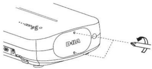
1 Remove the lamp cover
- Remove the screws with a screwdriver.
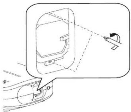
② Loosen the screws on the lamp unit
- Loosen the screws with a screwdriver.
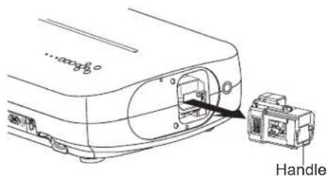
③ Pull out the lamp unit
- Grasp the handle and pull out the lamp unit.
4 Install the new lamp unit
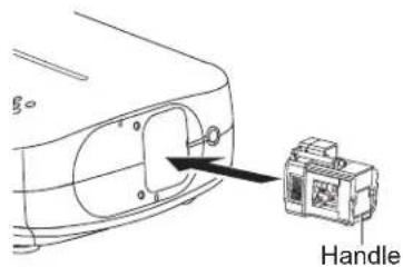
5 Tighten the screws of the new lamp unit
- Tighten the screws with a ⭕screwdriver.
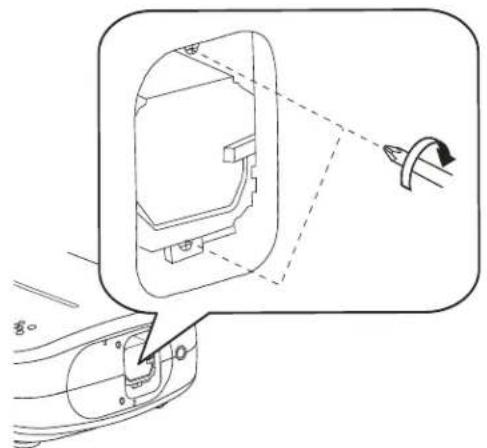
natural_image
Technical line drawing of a mechanical component with a magnified inset showing a curved bracket and a separate view (no text or symbols)6 Attach the lamp cover
- Insert the top part (with 2 claws) of the lamp cover into the unit.
- Fasten the screws with a +screwdriver.
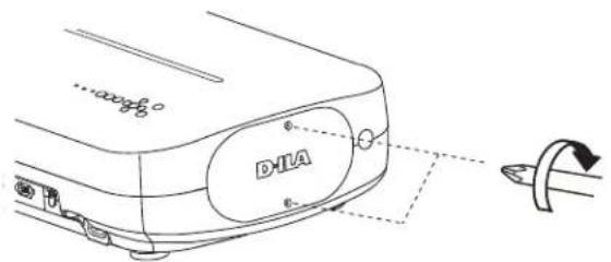

CAUTION
- Use only genuine replacement parts for the lamp unit. Also, never attempt to reuse an old lamp unit. This may cause a malfunction.
- Do not touch the surface of a new lamp. This may shorten the lamp life and cause lamp blowout.
MEMO
After Replacing the Lamp
- Do not place the removed lamp unit at locations that is reachable by children or near combustible items
- Dispose used lamp units in the same way as fluorescent lamps Follow your local community rules for disposal.
Replacing the Lamp (continued)

CAUTION
- Reset the lamp time only when you have replaced the lamp.
● Never reset the service time when the lamp is still in use. Otherwise, the approximate standard for gauging replacement time may be inaccurate and lamp blowout may occur.
Resetting Lamp Time
After replacing the lamp, reset the lamp time.
1 Insert the power plug to the power outlet
STANDBY/ON Light on (Red)
② Must operate with the remote control in the standby mode (the projector is powered, but is not turned on).
- Press in the order as shown.
- Press each button within 2-second intervals and press the last button for 2 seconds or more.
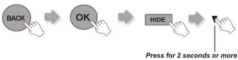
flowchart
graph LR
    A["BACK"] --> B["OK"]
    B --> C["HIDE"]
    C --> D["Press for 2 seconds or more"]
● [STANDBY/ON] indicator and [LAMP] indicator blink alternately for 3 seconds. After that, the unit switches to standby mode.
Cleaning and Replacing the Filter
Clean the filter regularly or air intake efficiency may deteriorate and malfunction may occur.
1 Remove the inner filter
Lift up while pushing the claw
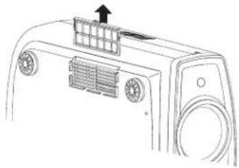
natural_image
Line drawing of a car air conditioner unit with ventilation slots and a mounted rack (no text or symbols)2 Clean the filter
natural_image
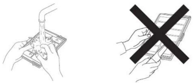
Two line drawings: one showing hands using a tool to clean or prepare, the other showing hands holding a device with a black X symbol (no text or symbols present)● Wash the filter with water and dry it in a shaded area.
- In extremely soiled cases, using a neutral detergent is recommended. Put on rubber gloves when using a neutral detergent.
● After washing the filter with water, make sure that it is completely dry before reinstalling. Otherwise electric shock or malfunctions may occur.
- Do not clean the filter with a vacuum cleaner or air duster. The filter is soft and may be damaged.
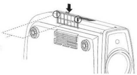
③ Reinstall the inner filter
Check that the left and right claws are locked onto the unit
natural_image
Technical line drawing of a device rear panel with ventilation slots and a downward arrow indicator (no text or symbols)
CAUTION
- Pull the power plug from the power outlet.

MEMO
If the filter is damaged or too dirty to be cleaned
- Replace with a new filter. A dirty filter will dirty the internal parts of the unit and cause shadows on the video image.
- To purchase a new filter or when it is dirty in the internal parts, consult your authorized dealer.
■ Inner Filter Part No.: Replacement Filter: the appearance is black PB006560999 (Inner Filter)
RS-232C Interface
Control of this unit via a computer is possible by connecting the computer to this unit with a RS-232C cross cable (D-Sub 9 pin).
RS-232C Specifications
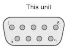
| Pin No. Signal | Function Signal Direction | ||
| 2 RxD | Receive data PC→This unit | ||
| 3 | TxD | Transmit data | This unit→PC |
| 5 GND | Signal ground | - | |
| 1,4,6 - 9 | N/C | - | - |
● PC refers to the controller such as a personal computer.
| Mode | Non-synchronous |
| Character Length | 8 bit |
| Parity | None |
| Start Bit | 1 |
| Stop Bit | 1 |
| Data rate | 19200 bps |
| Data format | Binary |
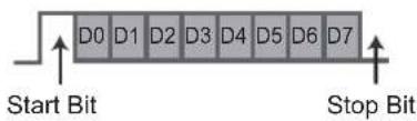
Command Format
The command between this unit and the computer consists of "Header", "Unit ID", "Command", "Data" and "End".
- Header (1 byte), Unit ID (2 bytes), Command (2 bytes), Data (n bytes), End (1 byte)
Header
This binary code indicates the start of communication.
| Binary code Type Description | ||
| 21 Operating command PC→This unit | ||
| 3F Reference command PC→This unit | ||
| 40 Response command This unit→PC | ||
| 06 ACK | This unit→PC(When the command is accepted without error, it returns to PC) |
Unit ID
This code specifies the unit. The binary code is fixed at "8901".
■ Command and data
Operating command and data (Binary code)
| Command Type | Data description | |
| 0000 Connection check | Check whether communication is available between this unit and the PC during standby. | |
| 5057 Power supply | During standby31: Turn on the power.During power on30: Turn off the power. (Standby mode) | |
| 4950 Input | During power on30: S-VIDEO31: VIDEO32: COMP.33: VGA36: HDMI 137: HDMI 2 | |
| 5243 Remote Control | Sends the same code as the supplied remote control.● “Remote control code” (P54) | |
Reference command and data (Binary code)
| Command Type | Data description | |
| 5057 Power supply | During standby or power on30: Standby mode31: Power-on mode32: During Cool Down mode34: Warning mode | |
| 4950 Input | During power on30: S-VIDEO31: VIDEO32: COMP.36: HDMI 137: HDMI 2 |
End
This code indicates the end of communication. The binary code is fixed at
RS-232C Interface (continued)
■ Remote control code
● Binary code is sent during communication.
| Remote control button name | Binary code | Remote control button name | Binary code |
| ▲ | 37 33 30 31 TEST 37 33 | 35 39 | |
| ▼ | 37 33 30 32 CINEMA 3 37 | 33 36 36 | |
| BACK 37 33 30 | 33 STAGE 37 33 36 37 | ||
| ON 37 33 30 | 35 CINEMA 2 37 33 36 38 | ||
| STAND BY 37 33 | 30 36 CINEMA 1 37 33 36 | 39 | |
| HIDE 37 33 31 | 44 NATURAL 37 33 36 41 | ||
| LENS.AP. 37 33 32 | 30 DYNAMIC 37 33 36 42 | ||
| MENU 37 33 32 | 45 | USER 1 37 33 36 43 | |
| OK | 37 33 32 46 | USER 2 37 33 36 | 44 |
| LENS | 37 33 33 30 | THX | 37 33 36 46 |
| ▶ | 37 33 33 34 | HDMI 1 37 33 37 | 30 |
| ◀ | 37 33 33 36 | HDMI 2 37 33 37 | 31 |
| MENU POSITION | 37 33 34 32 | PIC.ADJ. | 37 33 37 32 |
| PC | 37 33 34 36 | GAMMA 37 33 37 | 35 |
| VIDEO | 37 33 34 41 | C.TEMP 37 33 37 | 36 |
| S-VIDEO | 37 33 34 42 | ASPECT | 37 33 37 37 |
| COMP. | 37 33 34 43 |
RS-232C Communication Examples
This section shows the communication examples of RS-232C.
■ Operating command
| Type Command Description | ||
| Connection check | PC→This unit: 21 89 01 00 00 0AThis unit→PC: 06 89 01 00 00 0A | Connection check |
| Power (On) | PC→This unit: 21 89 01 50 57 31 0AThis unit→PC: 06 89 01 50 57 0A | When power is turned on from standby mode |
| Power (Off) | PC→This unit: 21 89 01 50 57 30 0AThis unit→PC: 06 89 01 50 57 0A | When power is turned off (standby mode) from power-on mode |
| Input (COMP.) | PC→This unit: 21 89 01 49 50 32 0AThis unit→PC: 06 89 01 49 50 0A | When video input is set to component |
| Remote Control (MENU) | PC→This unit: 21 89 01 52 43 37 33 32 45 0AThis unit→PC: 06 89 01 52 43 0A | When the same operation as pressing the [MENU] button on the remote control is made |
■ Reference command
| Type Command Description | ||
| Power (On) | PC→This unit: 3F 89 01 50 57 0AThis unit→PC: 06 89 01 50 57 0AThis unit→PC: 40 89 01 50 57 31 0A | When information of power-on mode is acquired |
| Input (S-VIDEO) | PC→This unit: 3F 89 01 49 50 0AThis unit→PC: 06 89 01 49 50 0AThis unit→PC: 40 89 01 49 50 30 0A | When information of S-VIDEO input is acquired |
Copyright and Caution
About Trademarks and Copyright
- HDMI, HDMI logo and high definition multimedia interface are trademarks or registered trademarks of HDMI Licensing LCC.
Caution
LCOS Device Characteristics
Do not project still pictures or pictures that have still segments for a long period of time. The still parts of the picture may remain on the screen.
Take special notice of images on the screens of video games and computer programs. There is no problem when playing normal video images such as movies.
When Unit is Unused for a Long Time
Prolonged disuse of the unit may effect an error on the functions. Turn on the power occasionally and operate the unit.
Usage Environment
- Avoid direct exposure of screen to direct sunlight and illumination. Block light using a curtain. Images can be well projected by darkening the brightness of the room.
- Do not use this unit in rooms with cigarette smoke or oily smoke. This may cause the unit to malfunction.
Parts Replacement
This unit contains parts (optical part, cooling fan, etc.) that require replacement to maintain its functioning. The estimated time for parts replacement varies greatly depending on the usage and environment. Please consult your authorized dealer for replacement.
Maintenance Procedures
Dirt on the cabinet
- Gently clean dirt on the cabinet with a soft cloth. In the case of heavy soiling, soak a cloth in water, wring dry and wipe, followed by wiping again with a dry cloth. Pay attention to the following as the cabinet may deteriorate in condition or paint may come off.
- Do not wipe with thinner or benzene.
- Do not spray with volatile chemicals like insecticide.
- Do not allow prolonged contact with rubber or plastic products.
Dirt in the air inlets
- Use a vacuum cleaner to suck up the dirt. Otherwise, use a cloth to wipe off the dirt. If dirt is allowed to accumulate in the air inlets, the internal temperature cannot be adjusted and this may cause a malfunction.
Dirt on the lens
- Clean the dirt using commercial blowers or lens cleaning papers for cleaning glasses and cameras. Do not use fluid-type cleaning agents. This may lead to peeling of the surface coating film.
Mounting this Unit
Measures to prevent the unit from toppling or dropping should be taken for safety reasons and accident prevention during emergencies including earthquakes.
When mounting this unit on a pedestal or ceiling, remove the 4 feet on the bottom surface and use all the 4 screw holes (M5 screws) to mount.
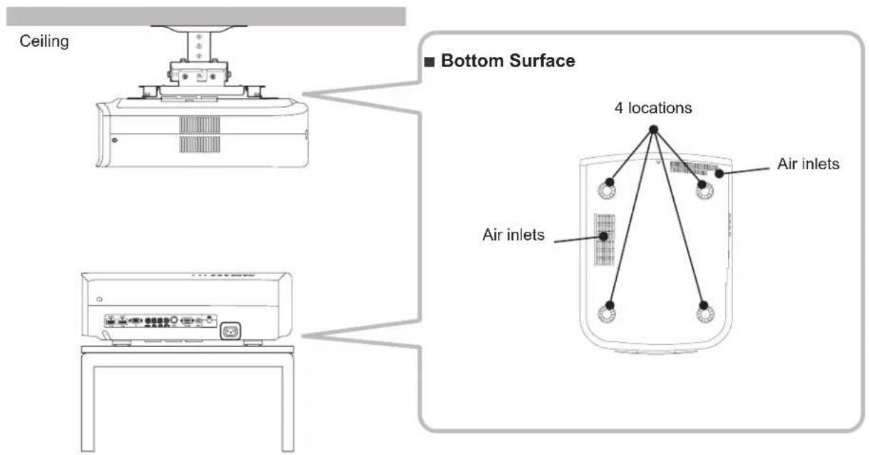
Precautions for Mounting
- Special expertise and techniques are required for mounting this unit. Be sure to ask your dealer or a specialist to perform mounting.
- Depth of the screw holes (screw length) is 23 mm. Use screws shorter than 23 mm but longer than 13 mm.
Using other screws will result in malfunctioning or cause the unit to drop.
- When mounting to a pedestal, ensure sufficient space (foot height of 10 mm or higher) around the unit so that the air inlets are not blocked.
-
Do not tilt this unit more than ±5 degrees from side to side when using.
-
Regardless whether the unit is still under guarantee, Anthem Electronics is not liable for any product damage caused by mounting the unit with non-Anthem Electronics ceiling fittings or when vvthe environment is not suitable for ceiling-mount.
- When using the unit hanging from a ceiling, pay attention to the surrounding temperature. When a heater is in use, temperature around the ceiling is higher than expected.
Specifications
| Product Name | LCOS Projector | |
| Model Name | LTX 500v | |
| Display Panel/Size | LCOS device ^1 ^2 /0.7" (1920 pixels x 1080 pixels) x 3 (Total no. of pixels: Approx. 6.22million) | |
| Projection Lens | 2.0 x power zoom lens (1.4:1 to 2.8:1) (Zoom/Focus:Power) | |
| Light-source Lamp | 200 W Ultra-high pressure mercury lamp [Part No.: BHL5010-S] | |
| Screen Size | Approx. 60" to 200" (Aspect ratio: 16:9) | |
| Objection Distance | Approx. 1.8m to 12m | |
| Color System | NTSC, NTSC4.43, PAL, PAL-M, PAL-N, SECAM (Auto/Manual switch) | |
| Analog Video Input Format | 480i, 480p, 576i, 576p, 720p/50Hz, 720p/60Hz, 1080i/50Hz, 1080i/60Hz | |
| Digital Video Input Format | 480i, 480p, 576i, 576p, 720p/50Hz, 720p/60Hz, 1080i/50Hz, 1080i/60Hz, 1080p/24Hz, 1080p/50Hz, 1080p/60Hz, PC compatible signals (P59) | |
| Resolution | 1920 dots x 1080 dots | |
| Color Management | Featured | |
| Terminals | ||
| Video Input(VIDEO) | 1-line, RCA pin jack x 11.0V (p-p), 75Ω | |
| S-video Input(S-VIDEO) | 1-line, mini DIN 4 pin x 1Y: 1.0V (p-p), 75ΩC: 0.286V (p-p), 75Ω (NTSC); 0.3V (p-p), 75Ω (PAL) | |
| Component Video InputCOMPONENT) | 1-line, RCA pin jack x 3Y: 1.0V (p-p), 75ΩCB/PB, CR/PR: 0.7V (p-p), 75Ω | |
| HDMI Input(HDMI 1, HDMI 2) | 2-line, HDMI 19 pin x 2 (HDCP compliant) ^3 | |
| PC Input | 1-line, D-Sub 15 pin VGA | |
| Trigger Output | 12V 100mA | |
| Power Requirements | AC 110V-240V 50/60 Hz | |
| Power Consumption | 280W (Standby mode: 1W) | |
| Operation Environment | Temperature: 5°C to 35°CHumidity: 20% to 80% (No condensation)(Storage Temperature: -10°C to 60°C) | |
| Installation Height | Below 1524m | |
| Dimensions(Width x Height x Depth) | 365mm X 167mm X 477.5mm | |
| Mass | 11.0Kg | |
| Accessories | (See P13) | |
*1 LCOS is the abbreviation for Liquid Crystal On Silicone.
*2 LCOS devices are manufactured using extremely high-precision technology. Pixel effectiveness is 99.99% . Only 0.01% or less of the pixels are either missing or would remain permanently lit up.
*3 HDCP is the abbreviation for High-bandwidth Digital Content Protection system.
The image of HDMI input terminal may not be displayed due to HDCP specification change.
- Design and specifications are subject to change without prior notice.
- Please note that some of the pictures and illustrations may have been abridged, enlarged or contextualized in order to aid comprehension. Images may differ from the actual product.
■ PC compatible signals
HDMI
| No. | Designation | Resolution | fh [kHz] | fv [Hz] | Dot CLK [MHz] | Polarity | Total No. of dots [dot] | Total No. of lines [line] | No. of effective dots [dot] | No. of effective lines [line] | |
| H | V | ||||||||||
| 1 VGA | 60 640 X 4 | 80 31.500 60 | .000 25.20 | 0 -- 800 52 | 5 640 480 | ||||||
| 2 VGA | 59.94 640 X | 480 31.469 | 59.940 25 | .175 -- 800 | 525 640 480 | ||||||
| 3 | SVGA 60 | 800 X 600 | 37.879 | 60.317 | 40.000 | + | + | 1,056 | 628 | 800 | 600 |
| 4 | XGA 60 | 1024 X 768 | 48.363 | 60.004 | 65.000 | - | - | 1,344 | 806 | 1,024 | 768 |
| 5 | WXGA 60 | 1280 X 768 | 47.760 | 60.000 | 79.998 | - | + | 1,675 | 796 | 1,280 | 768 |
| 6 | WXGA +60 | 1440 X 900 | 55.919 | 59.999 | 106.470 | - | + | 1,904 | 932 | 1,440 | 900 |
| 7 | SXGA 60 | 1280 X 1024 | 63.981 | 60.020 | 108.000 | + | + | 1,688 | 1,066 | 1,280 | 1,024 |
| 8 | WSXGA +60 | 1680 X 1050 | 65.222 | 60.002 | 147.140 | - | + | 2,256 | 1,087 | 1,680 | 1,050 |
| 9 | WUXGA 60 | 1920 X 1200 | 74.038 | 59.95 | 154.000 | + | - | 2,080 | 1,235 | 1,920 | 1,200 |
Images may not be displayed if the above timings are not met.
● PC (D-sub 3-lines 15 pins)
| No. | Designation | Resolution | fh [kHz] | fv [Hz] | Dot CLK [MHz] | Polarity | Total No. of dots [dot] | Total No. of lines [line] | No. of effective dots [dot] | No. of effective lines [line] | |
| H | V | ||||||||||
| 1 | VGA 60 | 640 X 480 | 31.500 | 60.000 | 25.175 | - | - | 800 | 525 | 640 | 480 |
| 2 | VGA 72 | 640 X 480 | 37.900 | 72.000 | 31.500 | - | - | 832 | 520 | 640 | 480 |
| 3 | VGA 75 | 640 X 480 | 37.500 | 75.000 | 31.500 | - | - | 840 | 500 | 640 | 480 |
| 4 | VGA 85 | 640 X 480 | 43.300 | 85.000 | 36.000 | - | - | 832 | 509 | 640 | 480 |
| 5 | SVGA 56 | 800 X 600 | 35.200 | 56.000 | 36.000 | + | + | 1024 | 625 | 800 | 600 |
| 6 | SVGA 60 | 800 X 600 | 37.900 | 60.000 | 40.000 | + | + | 1056 | 628 | 800 | 600 |
| 7 | SVGA 72 | 800 X 600 | 48.100 | 72.000 | 50.000 | + | + | 1040 | 666 | 800 | 600 |
| 8 | SVGA 75 | 800 X 600 | 46.900 | 75.000 | 49.500 | + | + | 1056 | 625 | 800 | 600 |
| 9 | SVGA 85 | 800 X 600 | 53.700 | 85.000 | 56.250 | + | + | 1048 | 631 | 800 | 600 |
| 10 | XGA 60 | 1024 X 768 | 48.400 | 60.000 | 65.000 | - | - | 1344 | 806 | 1024 | 768 |
| 11 | XGA 70 | 1024 X 768 | 56.500 | 70.000 | 75.000 | - | - | 1328 | 806 | 1024 | 768 |
| 12 | XGA 75 | 1024 X 768 | 60.023 | 75.029 | 78.750 | + | + | 1312 | 800 | 1024 | 768 |
| 13 | XGA 85 | 1024 X 768 | 68.700 | 85.000 | 94.500 | + | + | 1376 | 808 | 1024 | 768 |
| 14 | WXGA 60 | 1280 X 768 | 47.760 | 60.000 | 79.998 | - | + | 1675 | 796 | 1280 | 768 |
| 15 | WXGA+ 60 | 1440 X 900 | 55.919 | 59.999 | 106.470 | - | - | 1904 | 932 | 1440 | 900 |
| 16 | SXGA 60 | 1280 X 1024 | 63.981 | 60.020 | 108.000 | + | + | 1688 | 1066 | 1280 | 1024 |
| 17 | SXGA+ 60 | 1400 X 1050 | 64.740 | 59.950 | 101.000 | + | + | 1560 | 1080 | 1400 | 1050 |
| 18 | WSXGA+ 60 | 1680 X 1050 | 65.222 | 60.002 | 147.140 | - | - | 2256 | 1087 | 1680 | 1050 |
| 19 | 1920x1080 60 | 1920 X 1080 | 67.500 | 60.00 | 148.500 | + | + | 2200 | 1125 | 1920 | 1080 |
| 20 MAC13" | 640 X 480 | 35.000 | 66.667 | 30.240 | - | - | 864 | 525 | 640 | 480 | |
| 21 MAC16" | 832 X 624 | 49.107 | 75.087 | 55.000 | - | - | 1120 | 654 | 832 | 624 | |
| 22 MAC19" | 1024 X 768 | 60.241 | 74.927 | 80.000 | - | - | 1328 | 804 | 1024 | 768 | |
Images may not be displayed if the above timings are not met.
Specifications (continued)
Dimensions
■ Top Surface
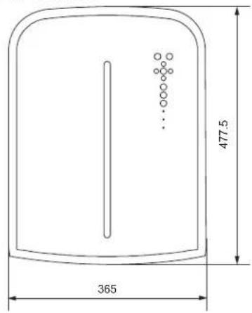
■ Bottom Surface

(Unit: mm)
Front
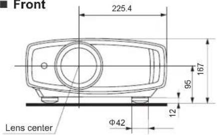
■ Back Surface
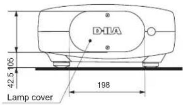
Limited Warranty
CANADA & USA
Anthem Electronics warrants to the original purchaser that each Anthem LTX projector is free from defects in workmanship and materials, during normal use and service, for a period of two (2) years from the date of sale, one (1) year for the remote control and six (6) months for the projector lamp. This warranty is not transferable unless the product is traded-in with an Authorized Anthem Dealer. During the warranty period, Anthem Electronics will repair or replace any defective components free of charge.
Warranty is void if the Anthem product is not purchased from an Authorized Anthem Dealer, if the serial number has been removed, altered, or defaced, if the product has been operated or handled other than in accordance with the instructions in its Operating Manual or otherwise abused, misused, damaged by accident or while in transport, tampered with, modified, or repaired by anyone other than Anthem Electronics or an authorized Anthem Electronics service center. If inspection by Anthem Electronics discloses that the repair required is not covered by this warranty, regular repair charges shall apply.
Display products sold by an Authorized Anthem Dealer are covered under the same warranty terms, except that the warranty period commences from the date of the dealer invoice, not the purchaser's invoice, and cosmetic flaws, if there are any, are excluded.
If a problem or defect is discovered in your Anthem projector, please contact the Authorized Anthem Dealer from whom you purchased the product. Your Dealer will help to determine the nature of the problem and arrange for the appropriate replacement parts, or the return of the product to Anthem Electronics. Alternatively, follow the procedure outlined below to obtain factory service.
A Return Authorization (RA) number must be obtained from Anthem Technical Support before any product can be returned to Anthem Electronics for any reason. The RA Number must be clearly visible on the outside of the shipping carton for Anthem Electronics to accept the return. Product shipped to Anthem Electronics without an RA Number will be refused and returned to the sender, freight collect. Product shipped to Anthem Electronics for repair must have shipping and insurance prepaid by the sender, be packaged in the original carton and packing material, and should be accompanied by a written description of the defect. Anthem Electronics will accept no responsibility for any damage occurring to a product that is shipped in any type of carton and packing material other than the original carton and packing material.
To receive service under warranty, an accompanying copy of the original sales receipt is required. Product repaired under warranty will be returned with shipping and insurance prepaid by Anthem Electronics (within Canada and USA only). All other repairs are subject to charges for labor, parts, return shipping, and insurance.
Disclaimer of Liability
Under no circumstances does Anthem Electronics assume liability or responsibility for injury or damages sustained in the use or operation of Anthem products, or for damages to any other connected products.
In no event shall Anthem Electronics, its agents, representatives, or employees, be responsible for any incidental or consequential damages. Some jurisdictions do not allow limitations of incidental or consequential damages, so this exclusion may not apply to you.
Anthem Electronics reserves the right to make design changes or improvements to products without any obligation to revise prior versions. All specifications are subject to change without notice.
On the expiration of the warranty period all liability of Anthem Electronics in connection with the product shall terminate.
This warranty constitutes the only warranty applicable to products sold by Anthem Electronics. No other warranty or condition, statutory or otherwise, expressed or implied, shall be imposed upon Anthem Electronics, nor shall any representation made by any person, including a representation by a representative or agent of Anthem Electronics, be effective to extend the warranty coverage provided herein.
INTERNATIONAL
Outside of Canada and USA, warranty coverage terms are set and maintained by the Authorized Anthem Distributor, not Anthem Electronics. Terms and conditions may vary.
MEMO
ANTHEM®
MANUEL D'INSTRUCTIONS
PROJECTEUR LCOS
LTX 500v
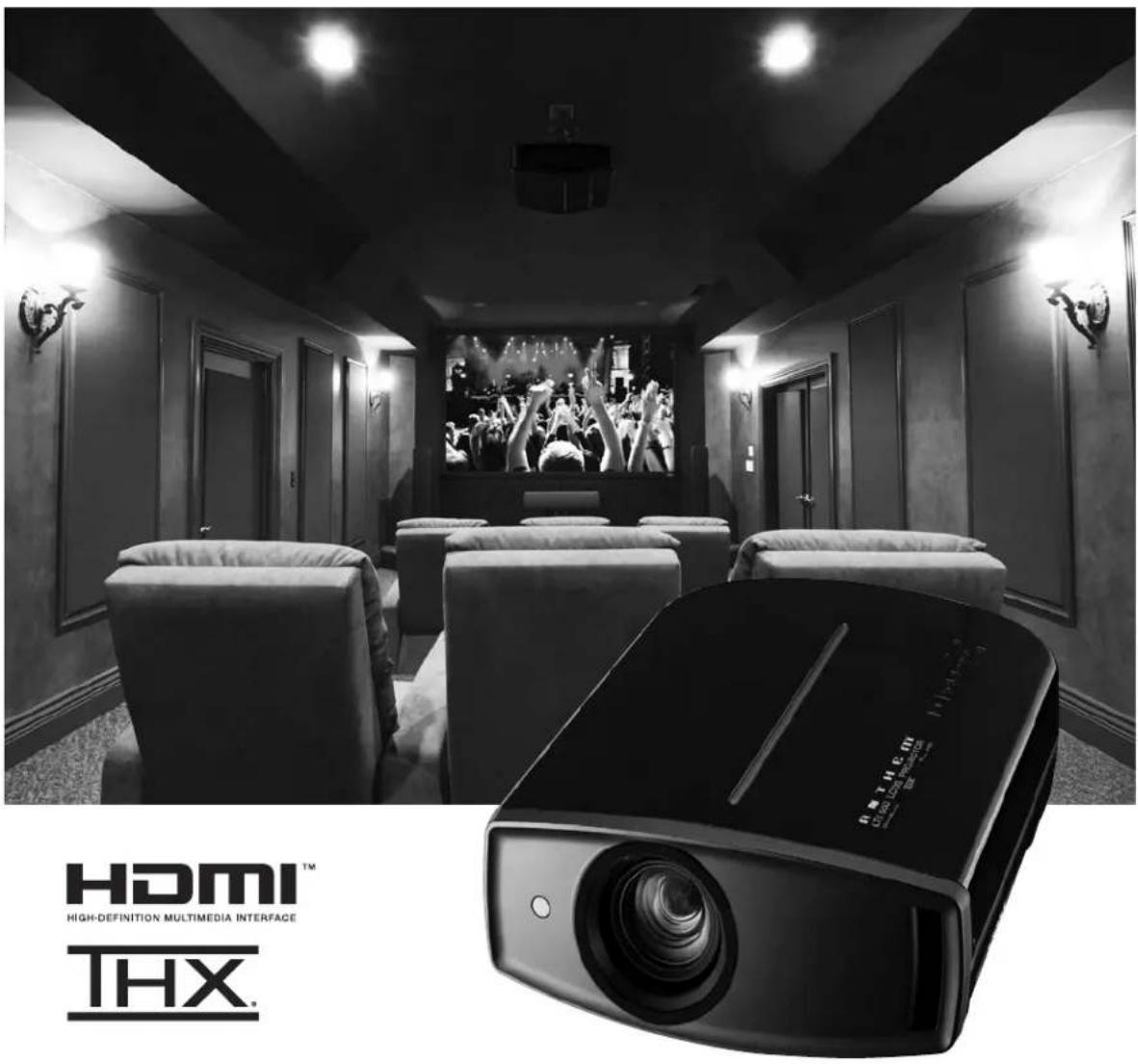
HDMI ^TM
HIGH-DEFINITION MULTIMEDIA INTERFACE
THX
PORTABLE CART WARNING (symbol provided by RETAC)

S3126A
Information for Users on Disposal of Old Equipment and Batteries

Products

Battery
[European Union only]
These symbols indicate that equipment with these symbols should not be disposed of as general household waste. If you want to dispose of the product or battery, please consider the collection systems or facilities for appropriate recycling.
Notice: The sign Pb below the symbol for batteries indicates that this battery contains lead.
DEUTSCH
Merk: Tegnet Pb under symbolet for batterier, viser at batteriet inneholder bly.
РУССКИЙ
Piles AAA ....2 cordons
natural_image
Simple line drawing of a door with a left-pointing arrow above it, no text or symbols present.②

③
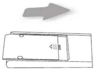
natural_image
Simple line drawing of a door with an arrow indicating direction (no text or symbols)natural_image
Illustration of desktop computers including a laptop, tower, and monitor (no text or symbols)PC
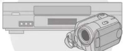
natural_image
Illustration of a vintage projector with a video camera shown in front (no text or symbols)Raccordements (Suite)
Raccordements (Suite)
natural_image
Black-and-white photo of a panda resting on dry grass near a tree (no text or symbols visible)natural_image
Black-and-white photo of two pandas resting in a natural enclosure (no text or symbols visible)3 Pour terminer

NOTE
natural_image
Simple diagram showing a circle inside a rectangle and an arrow pointing right, next to a blank rectangular box (no text or symbols)natural_image
Diagram showing a car interior with a dashed arrow indicating direction, no text or symbols presentnatural_image
Line drawing of a projector with an attached internal socket (no text or symbols)Poignée
natural_image
Technical line drawing of a mechanical component with a magnified inset showing a detail (no text or symbols)natural_image
Line drawing of a front-mounted air conditioner unit with cooling fins and a mounted panel (no text or symbols)natural_image
Two technical illustrations: one showing hands using a tool on a device, the other showing hands holding a device with a black X symbol (no text or labels present)natural_image
Line drawing of a device's front panel with scroll wheel and ventilation slots (no text or symbols)
AVERTISSEMENT
Interface RS-232C (suite)
PORTABLE CART WARNING
symbol provided by RETAD

S3126A
Information for Users on Disposal of Old Equipment and Batteries

Products

Battery
[European Union only]
These symbols indicate that equipment with these symbols should not be disposed of as general household waste. If you want to dispose of the product or battery, please consider the collection systems or facilities for appropriate recycling.
Notice: The sign Pb below the symbol for batteries indicates that this battery contains lead.
DEUTSCH
Merk: Tegnet Pb under symbolet for batterier, viser at batteriet inneholder bly.
РУССКИЙ
natural_image
Simple line drawing of a door with a left-pointing arrow above it, no text or symbols present.②
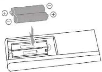
③
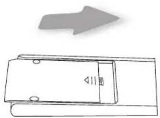
natural_image
Diagram of a door mechanism with an arrow indicating direction (no text or symbols present)natural_image
Illustration of desktop computers including a laptop, tower, and monitor (no text or symbols)PC
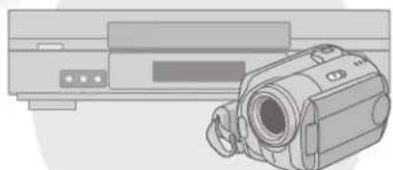
natural_image
Illustration of a vintage camera mounted on a rectangular device (no text or symbols visible)VCR y videocámara
Conexiones
natural_image
Diagram of a computer monitor rear panel showing ports and connectors (no text or labels)natural_image
Black-and-white photo of two red pandas resting on grassy ground, no visible text or symbolsnatural_image
Black-and-white photo of a panda resting on grass, no visible text or symbols③ Para terminar

MEMO
flowchart
graph LR
    A["Hand pointing at left"] --> B["BACKBACK"]
    B --> C["OK"]
    C --> D["Cancel with 'OK' button"]
natural_image
Diagram showing a car interior with a highlighted frame and an airplane icon, no text or symbols presentnatural_image
Technical line drawing of a mechanical component with a magnified inset showing a detail (no text or symbols)natural_image
Line drawing of a car air conditioner unit with ventilation slots and a directional arrow (no text or symbols)② Limpie el filtro
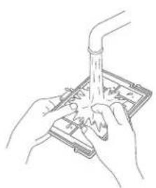
natural_image
Illustration of hands using a tool to test or prepare a sample on a device (no text or symbols visible)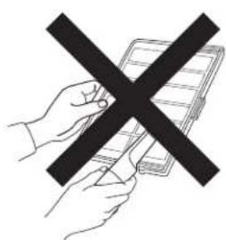
natural_image
Illustration of a hand holding a tablet with a black X symbol (no text or symbols present)
ADVERTENCIA
- MANUEL D'INSTRUCTIONS
- WARNING:
- CAUTION:
- FCC INFORMATION (U.S.A. only)
- NOTE:
- MACHINE NOISE INFORMATION (Germany only)
- About the installation place
- IMPORTANT SAFEGUARDS
- \*DO NOT allow any unqualified person to install the unit.
- Safety Precautions (Continued)
- POWER CONNECTION
- Do not cut off the main plug from this equipment.
- IMPORTANT (Europe only):
- Dear Customer,
- ENGLISH
- Information for Users on Disposal of Old Equipment and Batteries
- [European Union only]
- DEUTSCH
- РУССКИЙ
- THX CertificationTHX Certification
- THX
- THX Certification
- Contents
- Getting Started
- Preparation
- Basic Operation
- Settings
- Troubleshooting
- Others
- How to Read this Manual/Accessories/Optional Accessories
- About this Manual
- ■ Conventions in this manual
- Check the Accessories
- Optional Accessories
- Controls and features
- ■ Front Side/Left Side
- CAUTION
- ■ Rear Side/Top Side/Right Side
- ■ Bottom Surface
- Controls and features (continued)
- How to Use the Remote control
- Loading Batteries
- Effective Range of Remote Control Unit
- ■ When directing the remote control toward this unit
- ■ When reflecting off a screen
- Selecting Connecting Devices
- Connecting
- Connecting via Video Cable and S-Video Cable
- Connecting via Component Video Cable
- Connecting (continued)
- Connecting via HDMI Cable
- Connecting via HDMI-DVI Conversion Cable
- Connecting via SCART-RCA Cable
- Connecting via RGB Video Cable
- Connecting via PC Cable
- Connecting via Trigger Cable
- Installing the Projector and Screen
- Set Angle
- Shift
- ■ Left/Right position
- ■ Up/Down position
- ■ Shifting range of projected image
- (continued)
- Screen Size and Projection Distance
- MEMO
- Projecting Image
- Insert the power plug to the power outlet
- Turn on the power
- Project the image
- Select input mode
- Play back the selected device
- Adjusts image focus, size (zoom), and position (shift).
- Adjust the focus
- Adjust image position (shift).
- To end
- Turn off the power
- TIPS
- You can hide the image temporarily
- About Cool Down mode
- Convenient Features during Projection
- Setting the Screen Size
- Masking the Surrounding Area of an Image
- Project the image
- Mask the image
- Display the setting menu
- Select "Input Signal" → "Mask"
- Set a mask value
- To end
- The structure of the Settings menu
- Setting Menu
- Procedures for Menu Operation
- ② Select "Input Signal" → "Aspect (Video)"
- ③ Set to “16:9”
- Setting Menu (Continued)
- Installation > Installation Style
- Installation Style
- Installation > Keystone
- Keystone
- Installation > Screen Adjust
- Screen Adjust
- Display Setup > Back Color
- Back Color
- Display Setup > Menu Position
- Menu Position
- Display Setup > Menu Display
- Menu Display
- Customizing Projected Images
- Changing the Initial Setting of Picture Mode
- Select picture mode
- Adjust picture quality
- Other items can also be adjusted
- Registering User-defined Picture Mode
- Select the picture mode
- Registering User-defined Picture Mode from the Menu
- Adjust picture quality
- Display the setting menu
- ③ Select “Picture Adjust” → “Picture Mode” → “Natural”
- Register the setting
- What to Do When these Messages Are Displayed
- About Warning Indicators
- Actions to Be Taken for Warning Mode
- Replacing the Lamp
- Usable Lamp Life
- Purchasing the Lamp Unit
- Procedure for Lamp Replacement
- Remove the lamp cover
- ② Loosen the screws on the lamp unit
- ③ Pull out the lamp unit
- Install the new lamp unit
- Tighten the screws of the new lamp unit
- Attach the lamp cover
- After Replacing the Lamp
- Replacing the Lamp (continued)
- Resetting Lamp Time
- Cleaning and Replacing the Filter
- Remove the inner filter
- Clean the filter
- ③ Reinstall the inner filter
- If the filter is damaged or too dirty to be cleaned
- RS-232C Interface
- RS-232C Specifications
- Command Format
- Header
- Unit ID
- ■ Command and data
- End
- RS-232C Interface (continued)
- ■ Remote control code
- RS-232C Communication Examples
- Copyright and Caution
- About Trademarks and Copyright
- LCOS Device Characteristics
- When Unit is Unused for a Long Time
- Usage Environment
- Parts Replacement
- Maintenance Procedures
- Dirt on the cabinet
- Dirt in the air inlets
- Dirt on the lens
- Mounting this Unit
- Precautions for Mounting
- Using other screws will result in malfunctioning or cause the unit to drop.
- Specifications
- ■ PC compatible signals
- Specifications (continued)
- Dimensions
- Limited Warranty
- CANADA & USA
- Disclaimer of Liability
- INTERNATIONAL
- ANTHEM®
- PROJECTEUR LCOS
- LTX 500v
- Raccordements (Suite)
- Pour terminer
- NOTE
- AVERTISSEMENT
- Interface RS-232C (suite)
- Conexiones
- ③ Para terminar
- ② Limpie el filtro
- ADVERTENCIA
Brand : Anthem
Model : LTX 500v
Category : Projector