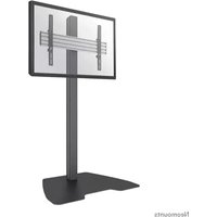
NMPRO-S1 - Monitor Stand NeoMounts - Free user manual and instructions
Find the device manual for free NMPRO-S1 NeoMounts in PDF.


User questions about NMPRO-S1 NeoMounts
0 question about this device. Answer the ones you know or ask your own.
Ask a new question about this device
Download the instructions for your Monitor Stand in PDF format for free! Find your manual NMPRO-S1 - NeoMounts and take your electronic device back in hand. On this page are published all the documents necessary for the use of your device. NMPRO-S1 by NeoMounts.
USER MANUAL NMPRO-S1 NeoMounts
natural_image
Abstract arrangement of black circles forming a cross-like pattern (no text or symbols)NEOMOUNTS PRO
BY NEWSTAR
natural_image
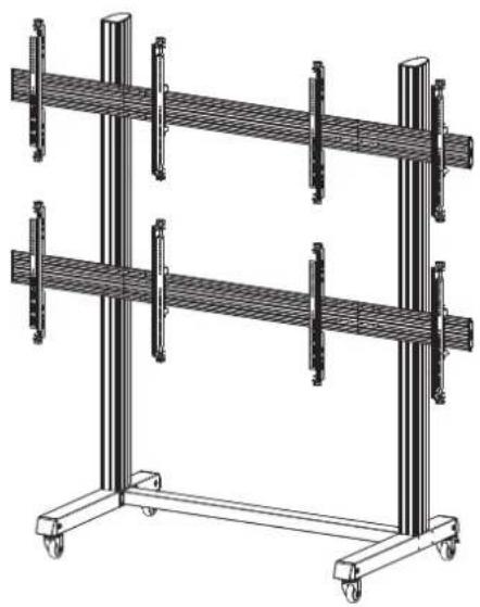
Technical line drawing of a dual-tiered storage rack with vertical supports and wheels (no text or symbols)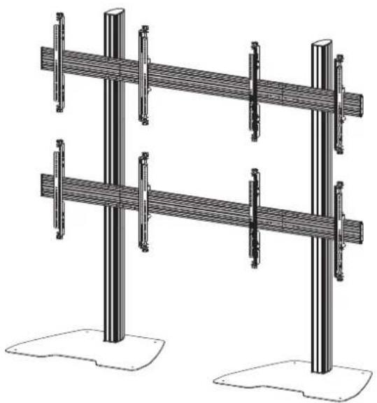
natural_image
Technical line drawing of two identical structural supports with vertical posts and mounting base (no text or symbols)MOBILE CARTS
STANDS
OVERVIEW
Section(1) With Wheels Page 2
natural_image
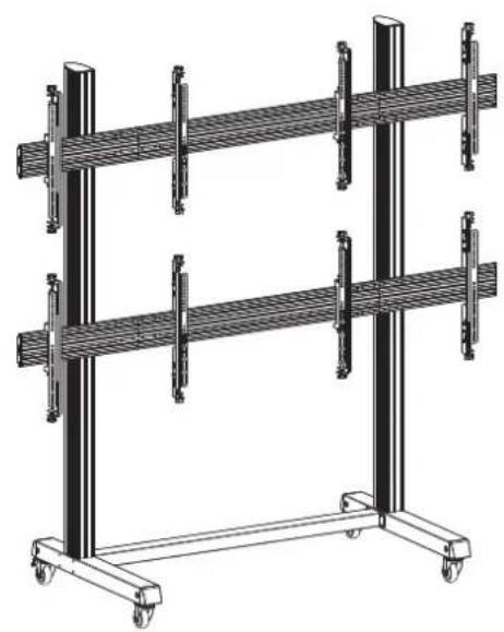
Technical line drawing of a multi-tiered vertical storage rack with railings and wheels (no text or symbols)Section(2) With Floor Plate Page 14
natural_image
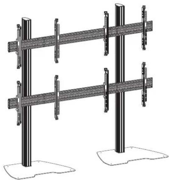
Technical line drawing of two identical vertical metal structures with support posts, mounted on base plates (no text or symbols)This instruction is applicable to all the following models and related extended products
Section(1) With Wheels
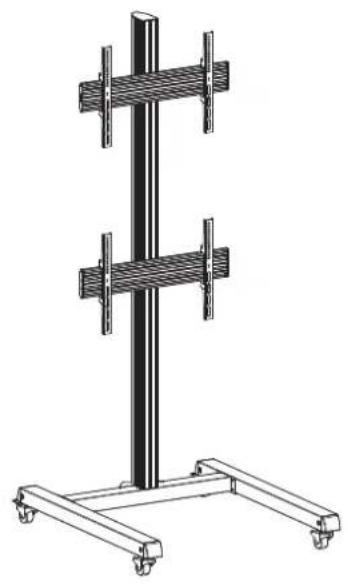
NMPRO-M21NMPRO-M12NMPRO-M22
(With fixed arms) (With fixed arms) (With micro-adjustment arms)
Page 12
natural_image
Technical line drawing of a vertical support structure with two horizontal plates and wheels (no text or symbols)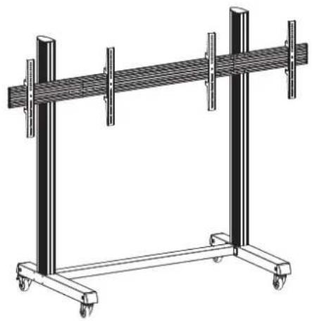
natural_image
Technical line drawing of a mechanical support frame with vertical supports and wheels (no text or symbols)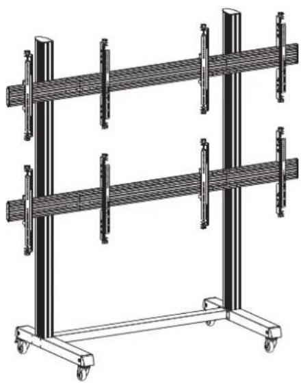
natural_image
Technical line drawing of a multi-tiered vertical storage or rack system with no visible text or symbolsNMPRO-M32 NMPRO-M33
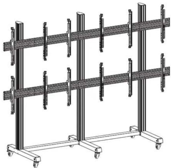
natural_image
Technical line drawing of a multi-tiered storage rack system with vertical supports and wheels (no text or symbols)(With micro-adjustment arms)(With micro-adjustment arms)
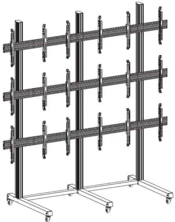
natural_image
Technical line drawing of a multi-tiered vertical storage rack system with wheels and vertical connectors (no text or symbols)WARNING
- Be sure to read this entire manual thoroughly and you fully understand all the instructions and warning before attempting to begin your installation.
- This products should only be installed by someone who has a basic knowledge of building construction installations and fully undestnd these instructions.
• Always have someone assit you to lift and position your equipment. - Tighten screws and bolts firmly, but do not over tighten. Over tightening can damage the item and greatly reduce their ability to hold. Please refer to suggested torque values where applicable in these instructions.
Parts list (NMPRO-M21)
| A1 | A2 | A3 | A4 |
| M5X15 M6X15 M8X15 3mm 5mm 6mm M8X12 | |||
| X4 | X4 | X4 | X4 |
M8X12 M8X4
X2
| B1 | B2 | B3 | B4 | B5 | B6 |
| M806X06.2X1.5 | X1 | X1 | X16 | X16 | X16 |
X1
| C1 | C2/C3 | C4 |
| X14 | X8 | X8 |
X1
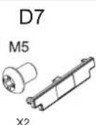
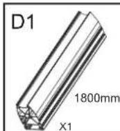
| D1 | D2 | D3 | D4 | D5 | D6 | D7 |
| 1500mmX2 | 1200mmX1 | 750mmX2 | X2 | X2 | X2 | |
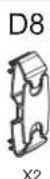
| D8 | 1000mm*1+480mm*2 | D9 | M5X2 | X8 | X4 | X4 |
Parts list (NMPRO-M22)
| A1 | A2 | A3 | A4 |
| M5X15 M6X15 M8X15 3mm 5mm 6mm M8X12 | |||
| X4 | X4 | X4 | X4 |
M8X12 M8X4
X4
| B1 | B2 | B3 | B4 | B5 | B6 |
| $M8∅6X∅6.2X1.5∅6X∅8.2X1.5 | |||||
| X1 | X1 | X1 | X34 | X34 | X34 |
X1
| C1 | C2/C3 | C4 |
| X14 | X8 | X8 |
X1
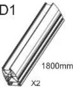 | 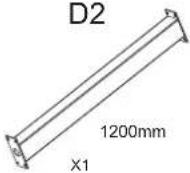 |  |  |  |  | 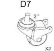 |
D8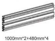 | 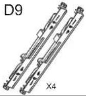 | D10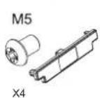 | D11 | D12 | D13 | D14 |
Parts list (NMPRO-M32)
| A1 | A2 | A3 | A4 |
| M5X15 M6X15 M8X15 3mm 5mm | 6mm M8X12 M8X12 M8X45 | ||
| (ZGDT) | [AYZZ) | [HXWK) | [WCKS] |
| X4 | X4 | X4 | X4 |
| C1 | C2/C3 | C4 |
| X25 | X12 | X8 |
 m m | 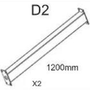 | 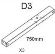 | 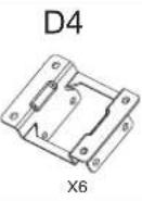 | 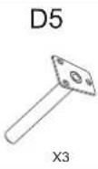 | 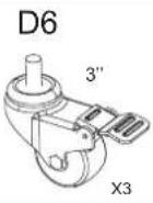 | 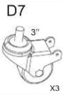 |
D8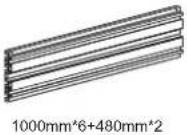 | 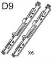 | 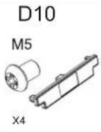 | 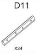 | 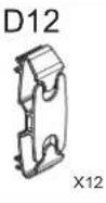 | 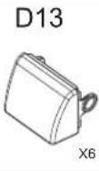 | 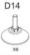 |
Parts list (NMPRO-M33)
| A1 | A2 | A3 | A4 |
| M5X15 M6X15 M8X15 3mm 5mm 6mm M9X12 M8X42 M8X45M8 | |||
 |  |  |  |
| X4 | X4 | X4 | X4 |
| C1 | C2 | C3 |
| [ |  m m | 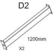 | 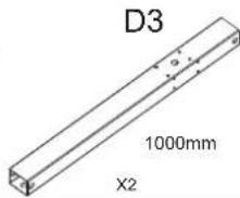 | 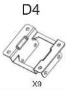 | 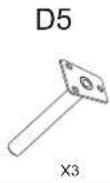 | 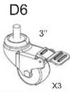 | 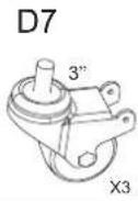 |
| D8 | 1000mm*9+480mm*3 | D9 | X9 | D10 | M5 | X6 | X36 |
Required Tools
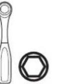 | ||||||||
| Socket Set | [×WTC] | [×DYC] | 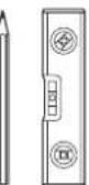 | 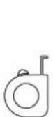 | 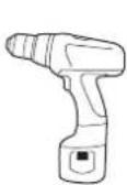 | 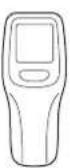 | 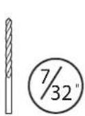 | 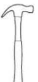 |
| Phillips Screwdriver | Pencil Level | Measuring Tape | Drill | Stud Finder | Wood Bit | Hammer | Masonry Bit | |
Installation
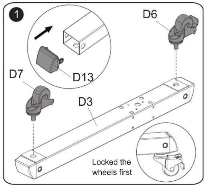
text_image
1 D6 D7 D13 D3 Locked the wheels first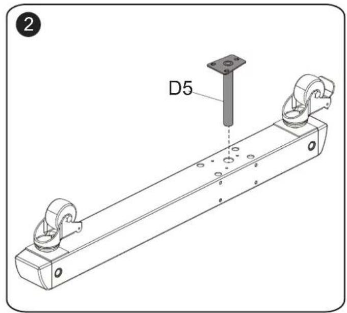
text_image
D5 2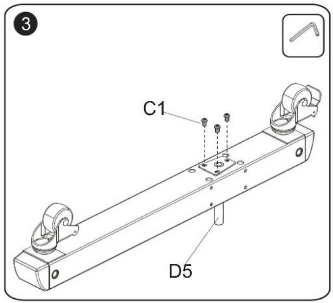
text_image
C1 D5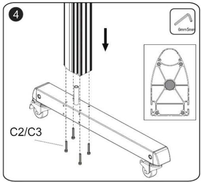
text_image
C2/C3 4 6mm5mm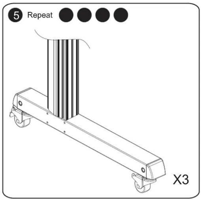
text_image
5 Repeat X3
text_image
6 C1 D2 5mm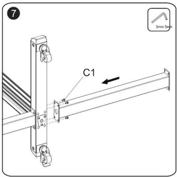
text_image
7 C1 5mm 5mm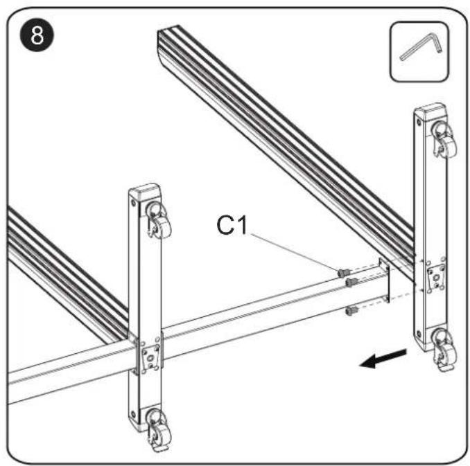
text_image
C1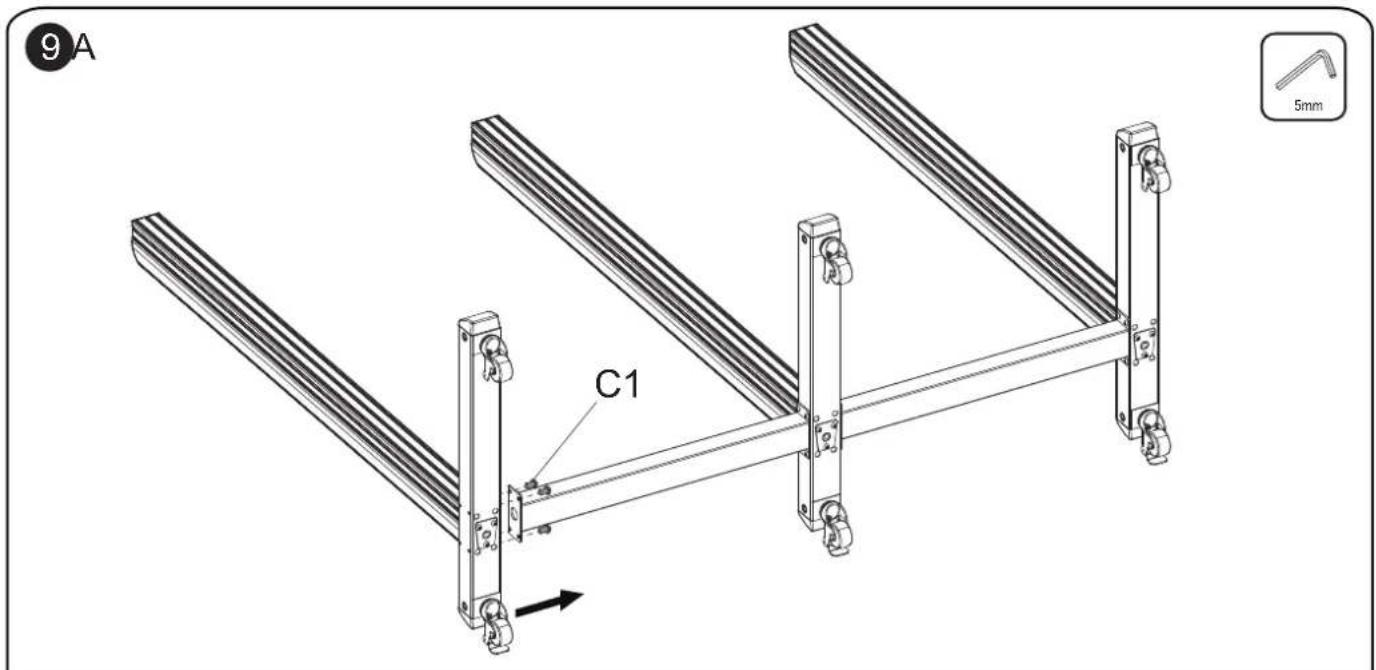
text_image
9A C1 5mm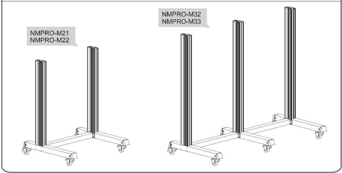
text_image
NMPRO-M21 NMPRO-M22 NMPRO-M32 NMPRO-M33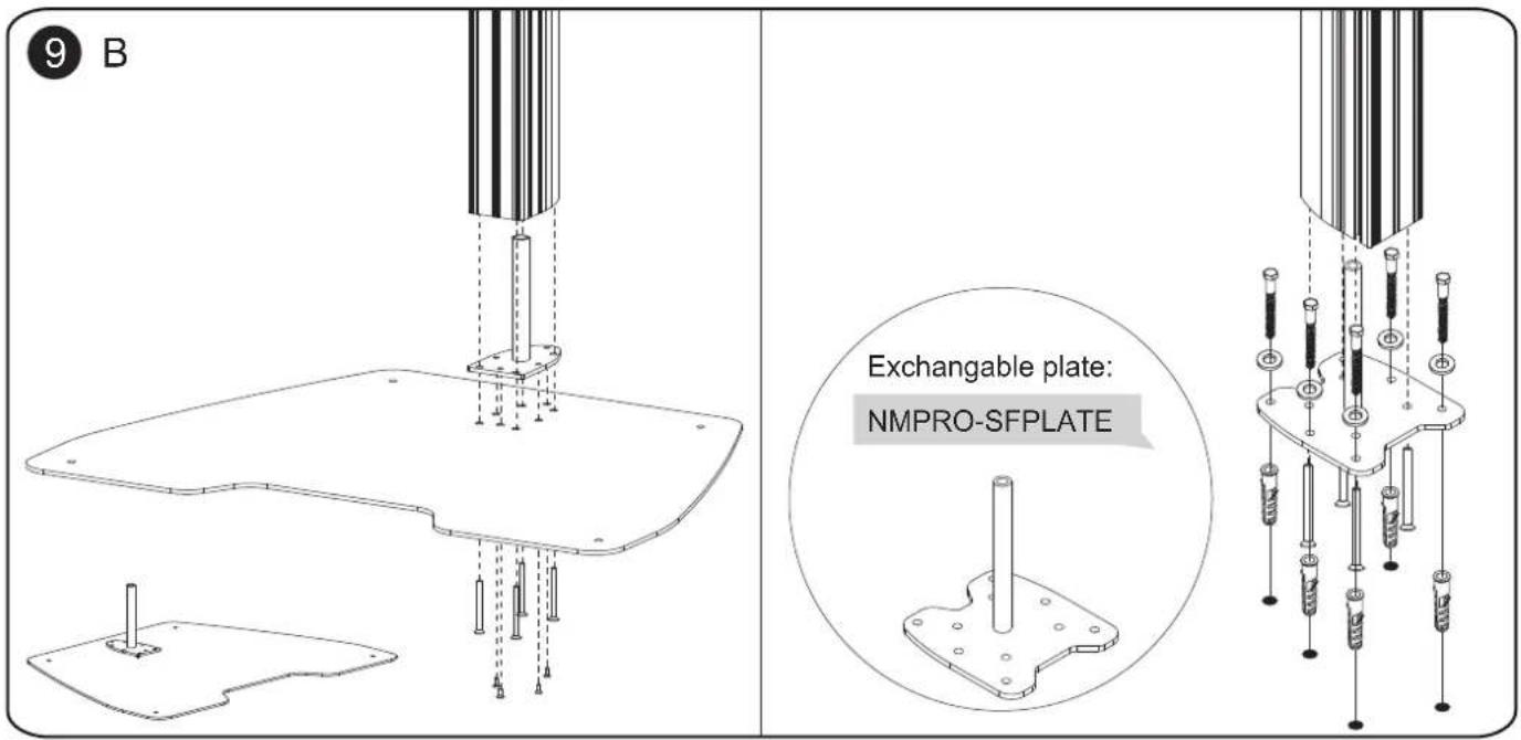
text_image
9 B Exchangeable plate: NMPRO-SFPLATE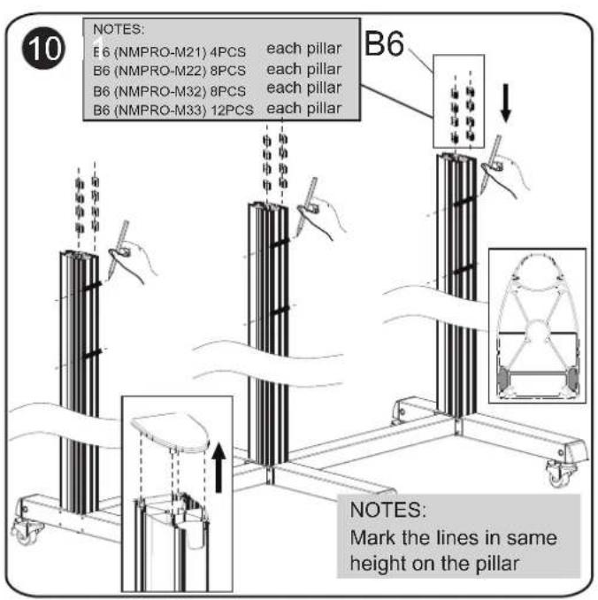
text_image
10 NOTES: E 6 (NMPRO-M21) 4PCS each pillar B6 (NMPRO-M22) 8PCS each pillar B6 (NMPRO-M32) 8PCS each pillar B6 (NMPRO-M33) 12PCS each pillar B6 NOTES: Mark the lines in same height on the pillar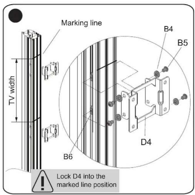
text_image
Marking line TV width B6 B4 B5 D4 Lock D4 into the marked line position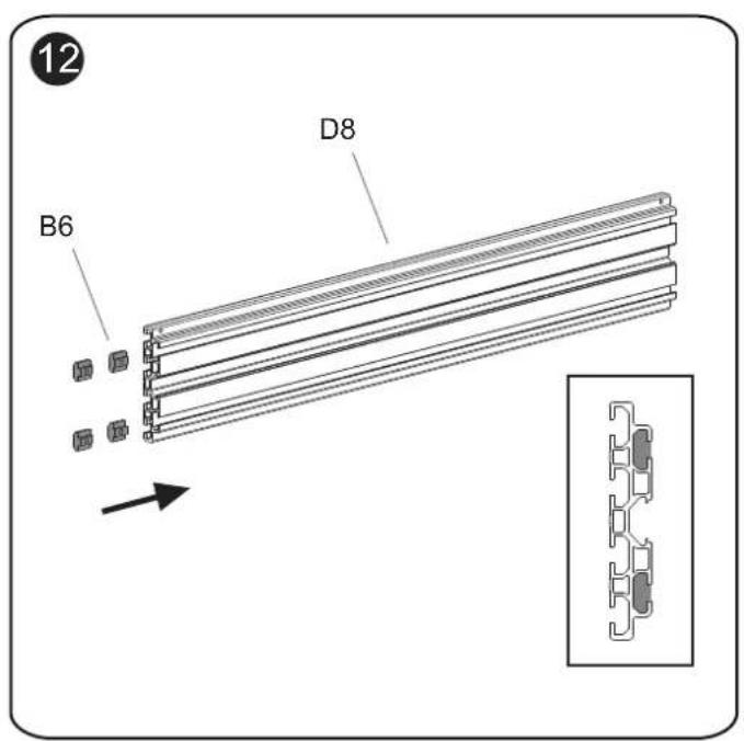
text_image
12 B6 D8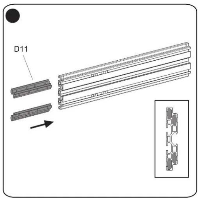
text_image
D11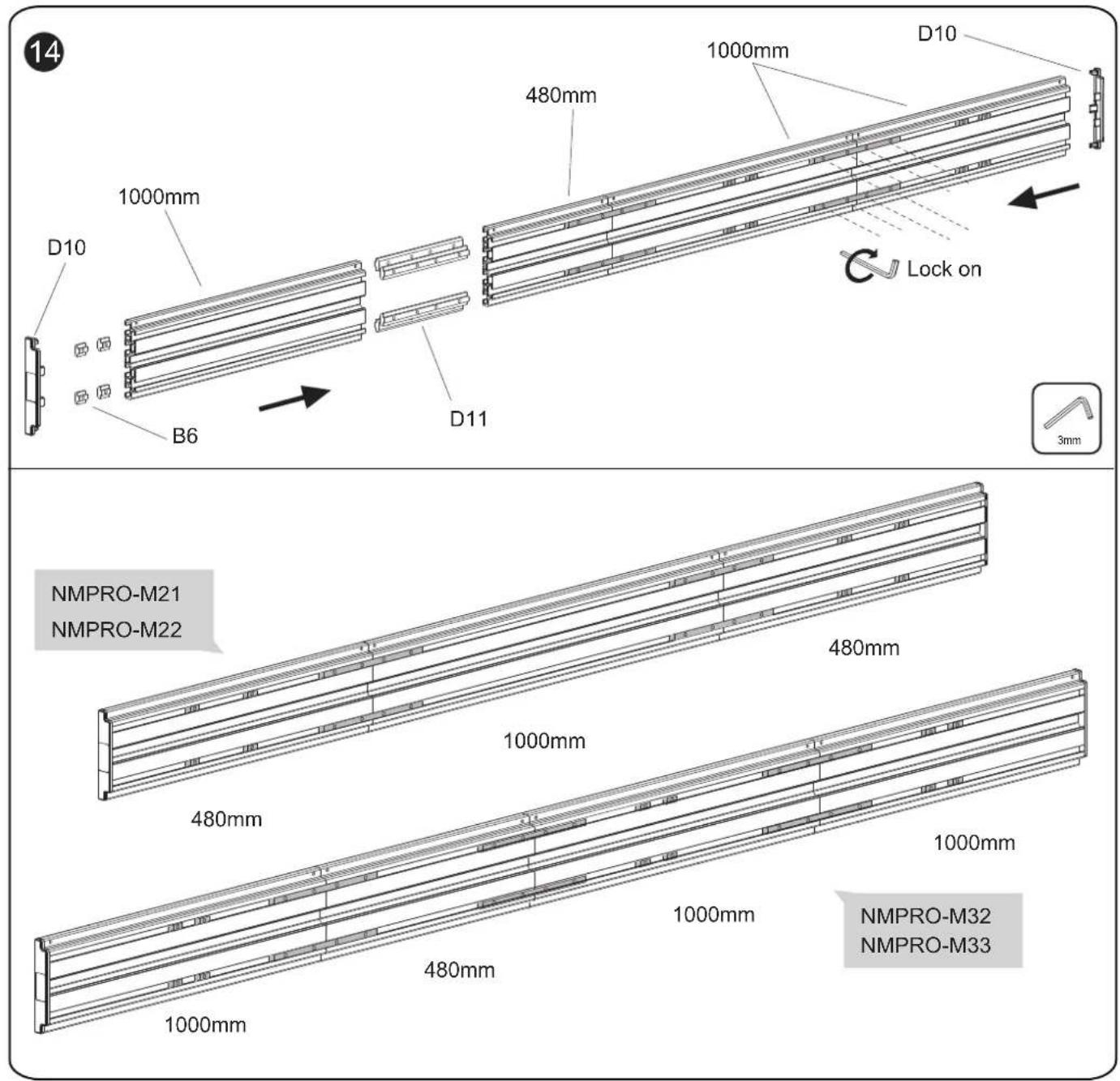
text_image
14 D10 1000mm 480mm 1000mm D10 B6 D11 Lock on 3mm NMPRO-M21 NMPRO-M22 480mm 1000mm 480mm 1000mm 480mm 1000mm NMPRO-M32 NMPRO-M33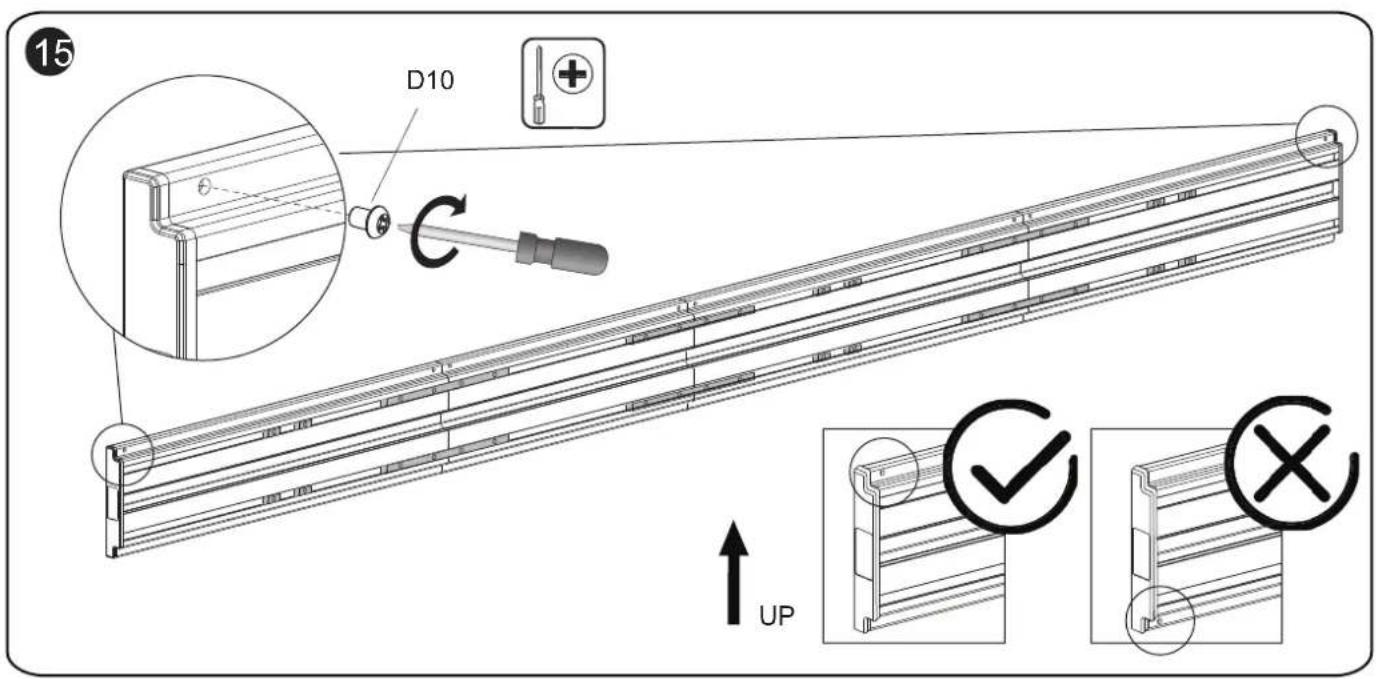
text_image
15 D10 UP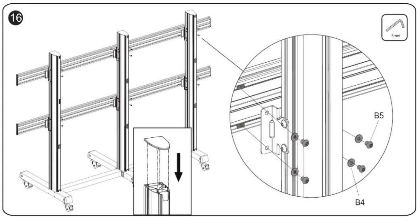
text_image
16 5mm B5 B4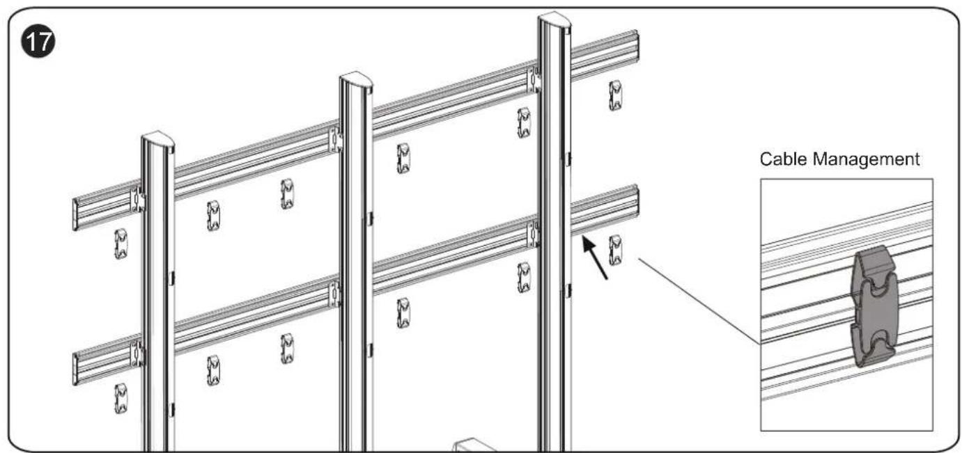
text_image
17 Cable Management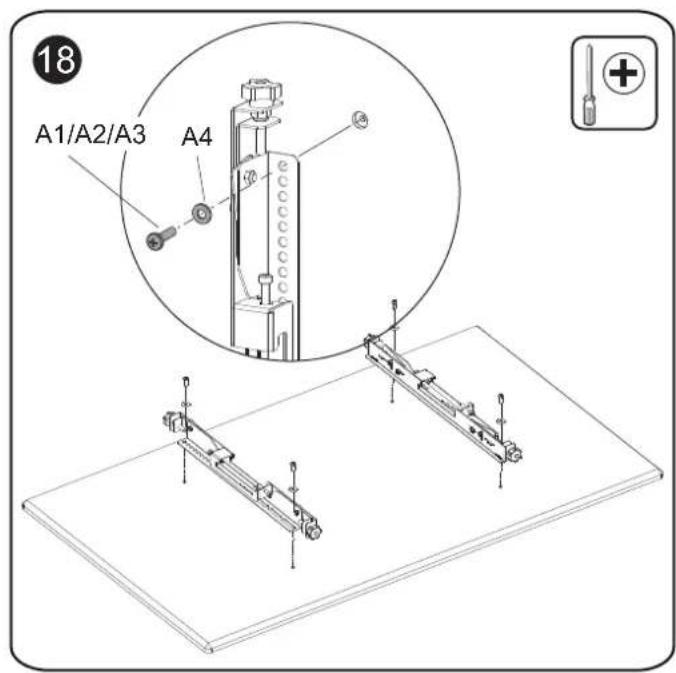
text_image
18 A1/A2/A3 A4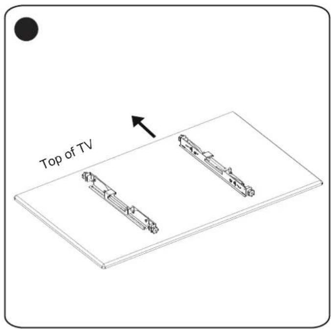
text_image
Top of TV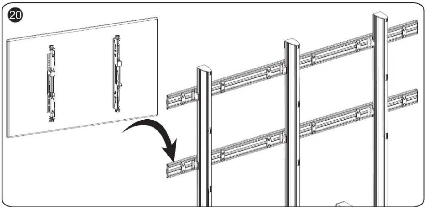
text_image
Technical diagram showing assembly steps of a metal fence structure with labeled components and a directional arrow indicating process.21
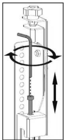
Adjust the vertical position of TV
Height
adjustment
10mm
natural_image
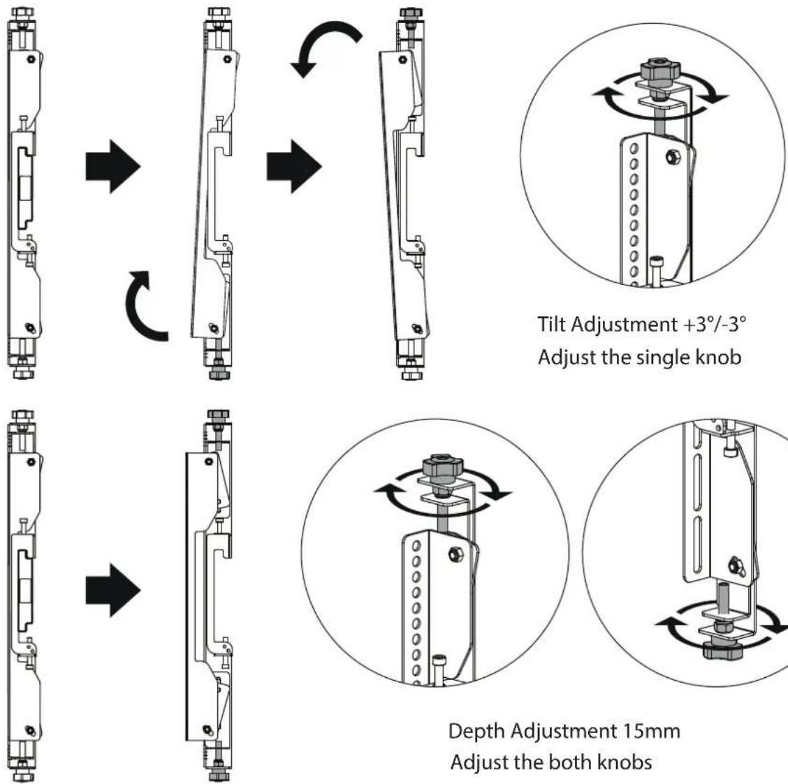
Technical diagram of a mechanical device with rotational arrows indicating motion (no text or symbols)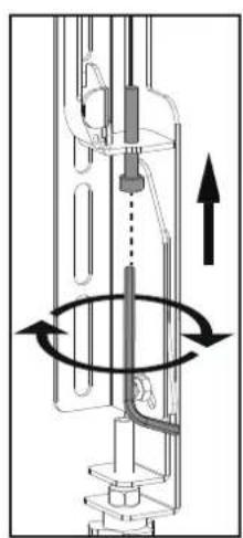
natural_image
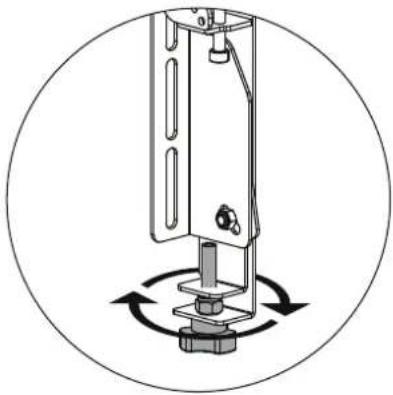
Mechanical assembly diagram showing a rotating shaft and housing with directional arrows indicating motion (no text or labels)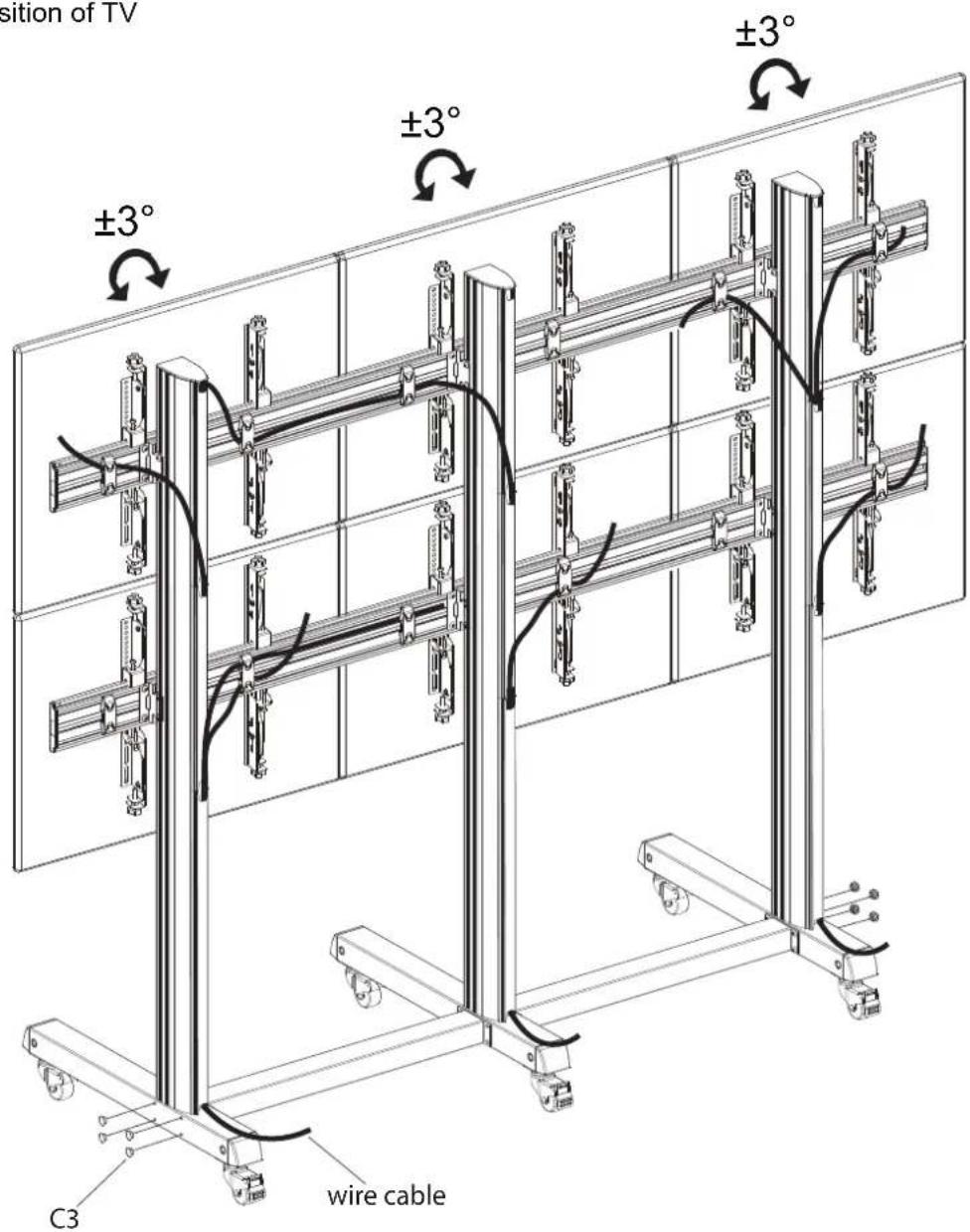
text_image
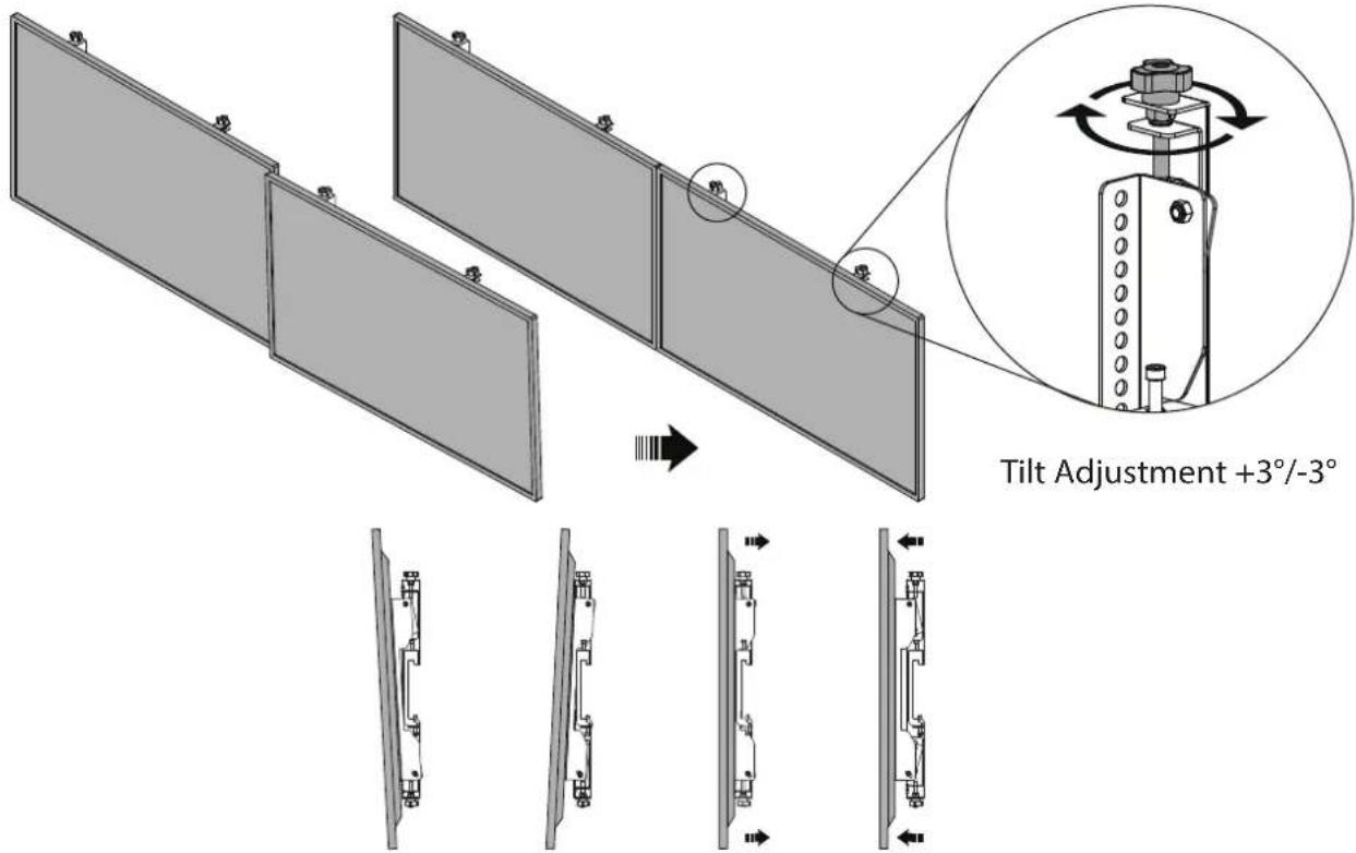
Position of TV ±3° ±3° ±3° C3 wire cable22
natural_image
Mechanical assembly diagram showing a vertical frame with mounting base and rotating components (no text or symbols)23
Parts list (NMPRO-M12)
| A1 | A2 | A3 | A4 |
| M5X15 M6X15 M8X15 5mm 6mm | M8X12 M8X | ||
| X4 X1 X1 X16 X16 X16 X14 X4 | X4 | ||
12 M8X45M8∅
| B1 | B2 | B3 | B4 | B5 | B6 |
X1
| C1 | C2/C3 | C4 |
X1
text_image
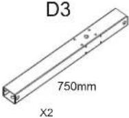
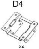
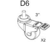
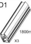
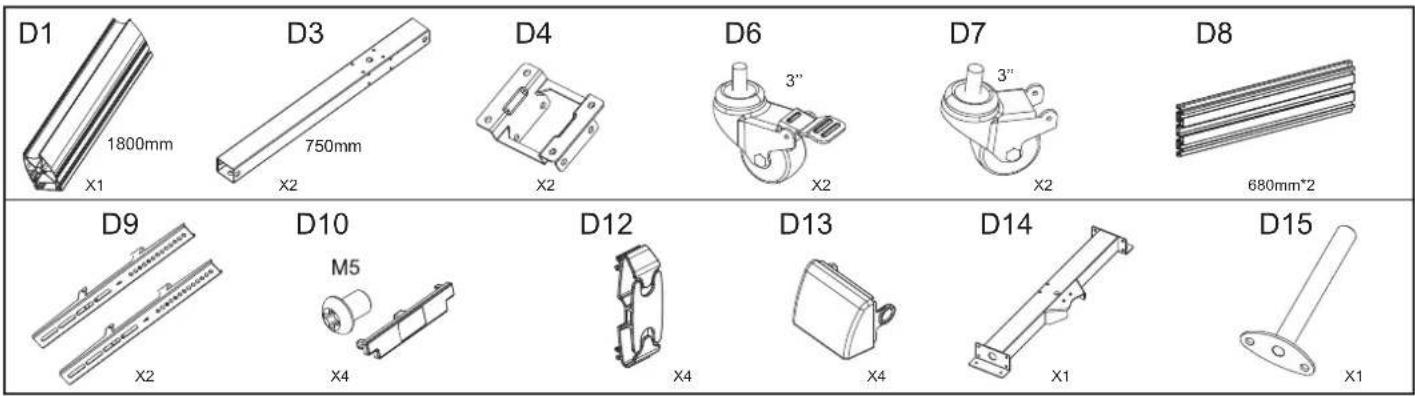
D1 1800mm X1 D3 750mm X2 D4 X2 D6 3" X2 D7 3" X2 D8 680mm*2 D9 X2 D10 M5 X4 D12 X4 D13 X4 D14 X1 D15 X1Installation
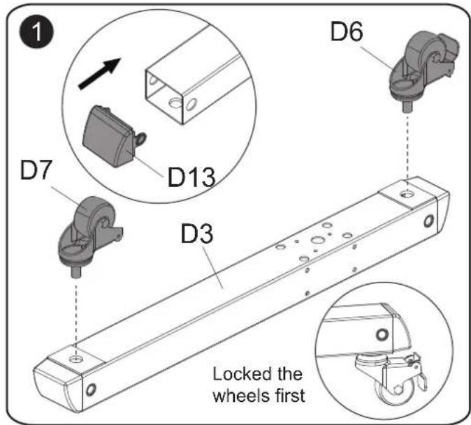
text_image
1 D6 D7 D13 D3 Locked the wheels first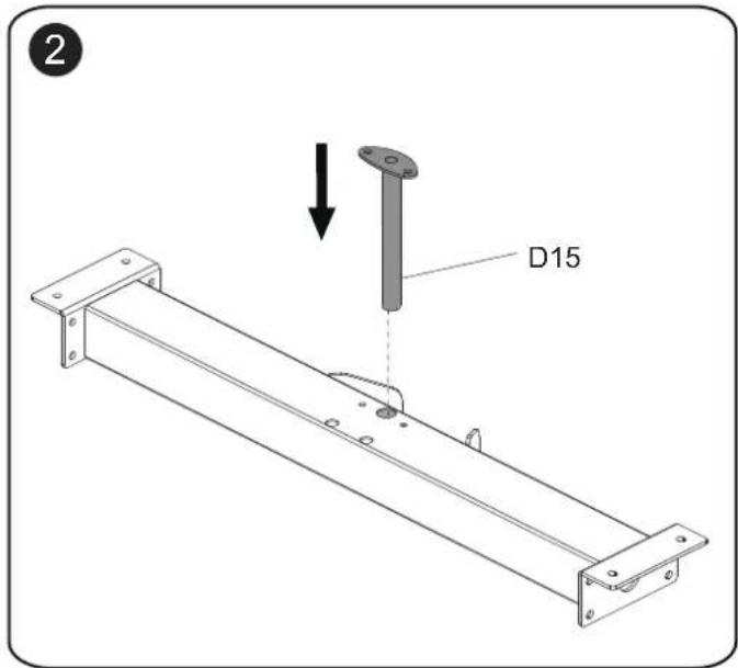
text_image
D15 ②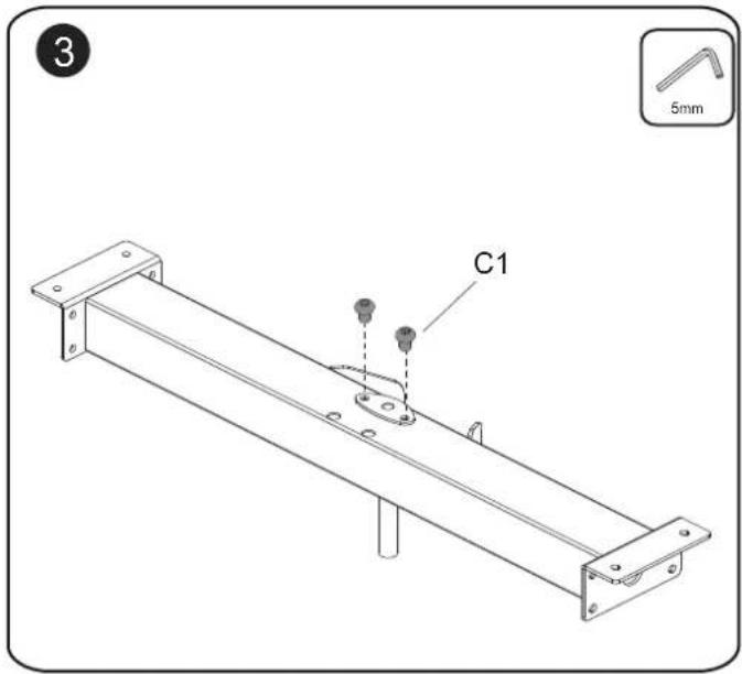
text_image
3 C1 5mm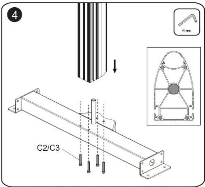
text_image
4 C2/C3 6mm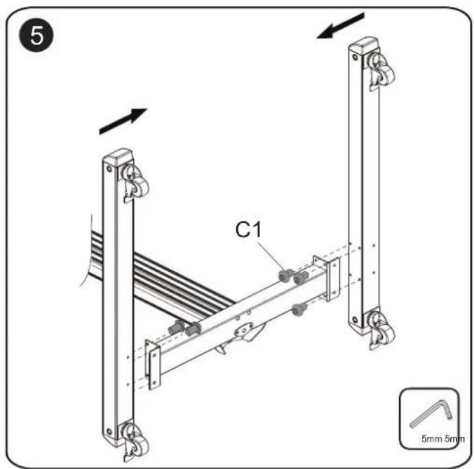
text_image
C1 5mm 5mm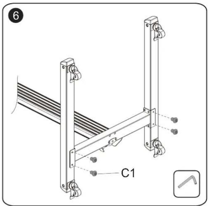
text_image
6 C1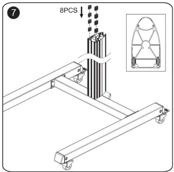
text_image
7 8PCS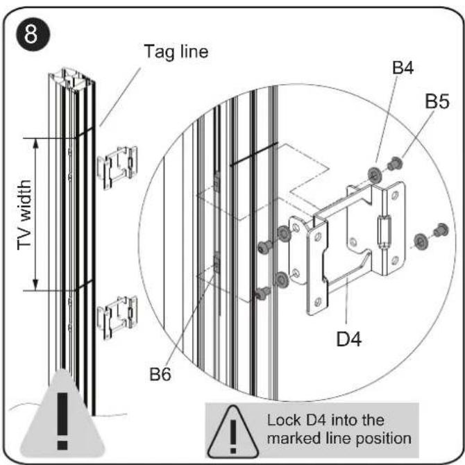
text_image
8 Tag line TV width B4 B5 D4 B6 Lock D4 into the marked line positionPlease refer to page 9 and 10 for the remaining steps.
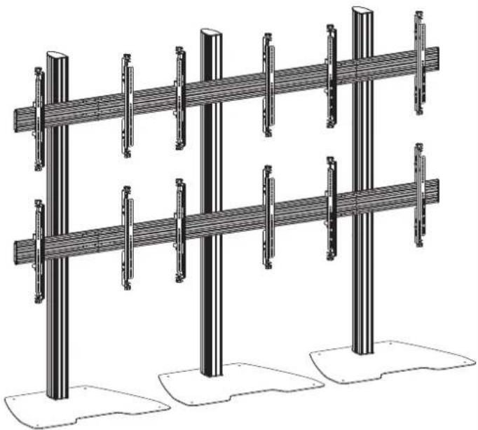
Section(2) With Floor Plate
NMPRO-S1 NMPRO-S12
(With fixed arms)
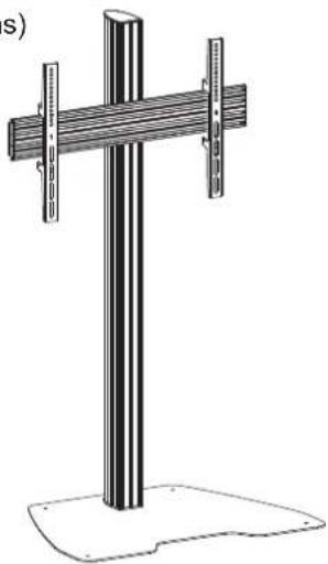
natural_image
Technical line drawing of a vertical support structure with two metal bars and a base (no text or symbols)(With fixed arms)
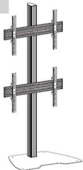
natural_image
Technical line drawing of a vertical support structure with two horizontal bars and a base (no text or symbols)NMPRO-S21 NMPRO-S22
(With fixed arms)
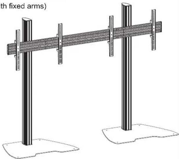
text_image
th fixed arms)(With micro-adjustment arms)
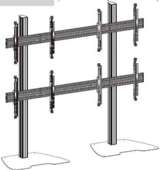
natural_image
Technical line drawing of two identical structural supports with vertical posts and support columns (no text or symbols)NMPRO-S32 NMPRO-S33
(With micro-adjustment arms)
natural_image
Technical line drawing of a multi-tiered structural framework with vertical supports and base platforms (no text or symbols)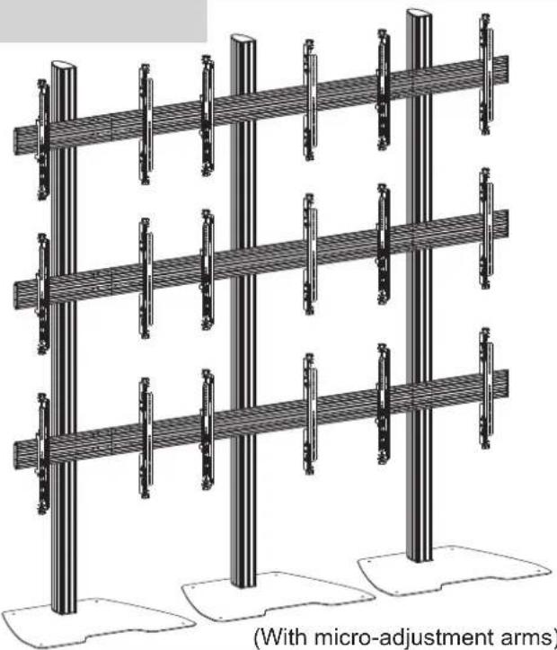
natural_image
Structural diagram of a multi-level support frame with vertical columns and horizontal beams, labeled 'With micro-adjustment arms' (no text or symbols on the structure itself)WARNING
- Be sure to read this entire manual thoroughly and you fully understand all the instructions and warning before attempting to begin your installation.
- This products should only be installed by someone who has a basic knowledge of building construction installations and fully undestnd these instructions.
• Always have someone assit you to lift and position your equipment. - Tighten screws and bolts firmly, but do not over tighten. Over tightening can damage the item and greatly reduce their ability to hold. Please refer to suggested torque values where applicable in these instructions.
Parts list (NMPRO-S1)
| A1 A2 A3 A4 | |||
| M5X15 M6X15 M8X15 5mm M8X15 X4 X1 X8 X8 X8X4 X4 X4 | .09X06 2X1.52 M8 | ||
X1 X1
| B2B1 B4 B5 B6 | ||||
| ∅0X∅8.2X1.5 | ||||
| C1 | C2 | C3 | C4 | C5 | C6 |
| M8X45 | M8X12 | Rubber Pad | Lag bell∅5X∅8.2X1.5 | Anchor | |
| X4 | X4 | X5 | X4 | X4 | X4 |
X1
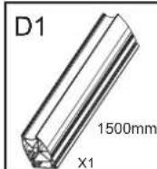
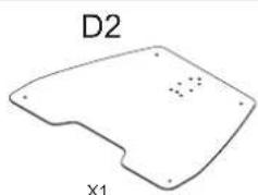
natural_image
Simple line drawing of a 3D object with labeled points D2 and X1 (no text or symbols on the shape itself)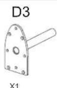
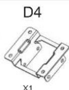
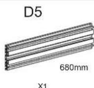
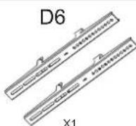
Parts list (NMPRO-S12)
| A1 A2 A3 A4 | |||
| M5X15 M6X15 M8X15 | ∅6X∅6 2X1.5 | ||
| X4 | X4 X4 X4 | ||
X2
| B2B1 B4 B5 B6 | ||||
| 36x05.2x15 | 5mm M8X12 M8 | |||
| X1 X16 | X16 | X16 | ||
X1
| C1 | C2 | C3 | C4 | C5 | C6 |
| M8X45 | M8X12 | Rubber Pad | Lag bolt 6 × 8.2 × 1.5 | Anchor | |
| X4 | X4 | X5 | X4 | X4 | X4 |
X1
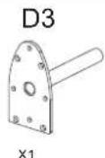
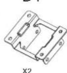
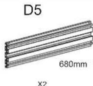
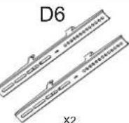
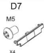
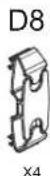
Parts list (NMPRO-S21)
| A1 | A2 | A3 | A4 |
| M5X15 M6X15 M8X15X4 | X4 | 5mm M8X12 M8X4 | 08X06 2X15X4 |
X2
| B1 | B2 | B4 | B5 | B6 |
| 3mm | ∅6X∅8.2X1.5 | |||
| X1 | X1 | X16 | X16 | X16 |
X1
| C2C1 C4C3 C5 C6 | |||||
| M8X45 | M8X12 06 X4X4 PadX4X4 X4 X4 X4X5 | Lag bolt | Anchor | ||
X2
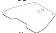
| D2 | D3 | D4 | D5 | D8 | D9 | ||
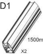 m m | 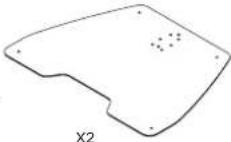 | 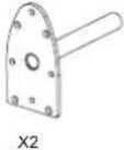 | 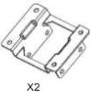 | 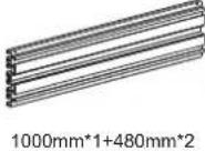 | 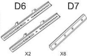 | 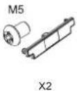 | 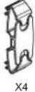 |
Parts list (NMPRO-S22)
| A1 | A2 | A3 | A4 |
| M5X15 M6X4 | X15 M8X15X4 | 5mm M8X12 | L00x06 2x1.5X4 |
X4
| B1 | B2 | B4 | B5 | B6 |
| 3mm | ∅6X∅8.2X1.5 | |||
| X1 | X1 | X34 | X34 | X34 |
X1
| C2C1 C4C3 C5 C6 | |||||
| M8X45 | M8X12 | Rubber Pad | Lag bolt∅6X0ft.2X1.5 | Anchor | |
| X4X4 X4 X4 X4X5 | |||||
X2
| D2 | D3 | D4 | D5 | D8 | D9 | ||
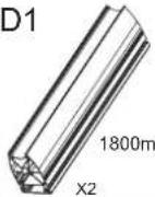 m m | 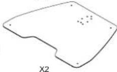 | 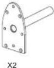 | 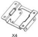 | 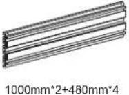 | 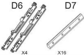 | 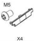 | 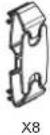 |
Parts list (NMPRO-S32)
| A1 | A2 | A3 | A4 |
| M5X15 M6X4 | X15 M8X15X4 | 5mm M8X4 | 12 M8X4 |
X6
| B1 | B2 | B4 | B5 | B6 |
| 3mm | ∅6X∅8.2X1.5 | |||
| X1 | X1 | X50 | X50 | X50 |
X1
| C2C1 | C4C3 | C5 | C6 | ||
| M8X45 | M8X12 | Rubber Pad | Lag bolt∅6X∅8.2X1.5 | Anchor | |
| X4X4 | X4 X4X4X5 |
X3
| D2 | D3 | D4 | D5 | D6 | D7 | D8 | D9 | |
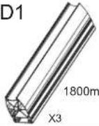 m m | 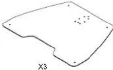 | 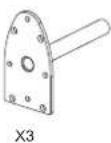 | 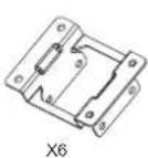 | 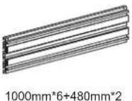 | 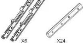 |  | [6VGK] |
Parts list (NMPRO-S33)
| A1 | A2 | A3 | A4 |
| M5X15 M6X15 M8X15X4 | X4 | 5mm M8X12 | 06X26 2X15M8X4 |
X9
| B1 | B2 | B4 | B5 | B6 |
| 3mm | ∅X08.2X1.5 | |||
| X1 | X1 | X74 | X74 | X74 |
X1
| C2C1 | C4C3 | C5 | C6 | ||
| M8X45 | M8X12 | Rubber Pad | Lag bolt.∅6X∅8.2X1.5 | Anchor | |
| X4X4 | X4 X4 X4X5 |
X3

text_image
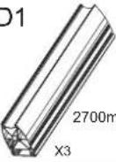
D1 2700mm X3 D2 X3 D3 X3 D4 X9 D5 1000mm*9+480mm*3 D6 X9 D7 X36 D8 M5 X6 D9 X18Required Tools

text_image
Socket Set Phillips Screwdriver Pencil Level Measuring Tape Drill Stud Finder Wood Bit Hammer Masonry BitInstallation
text_image
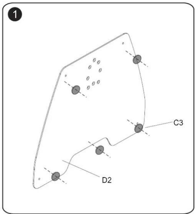
1 C3 D2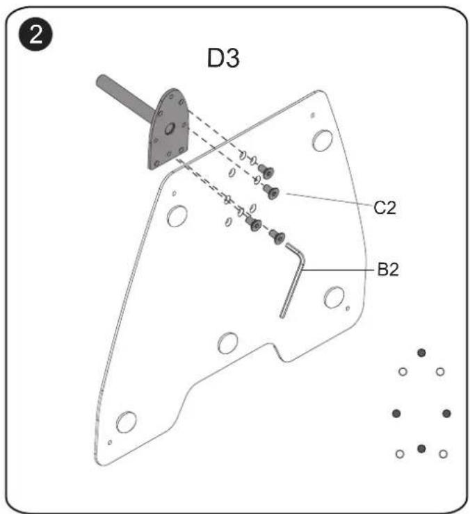
text_image
D3 C2 B2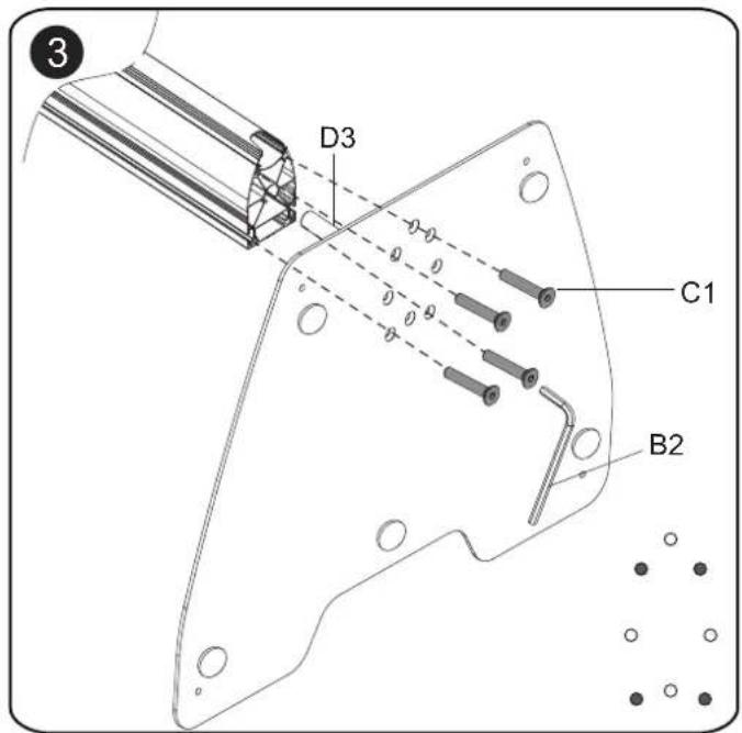
text_image
D3 C1 B2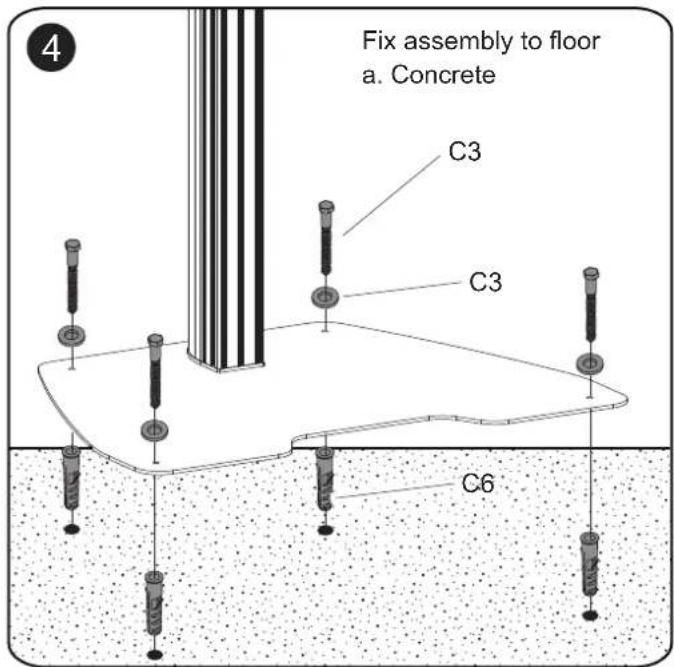
text_image
Fix assembly to floor a. Concrete C3 C3 C6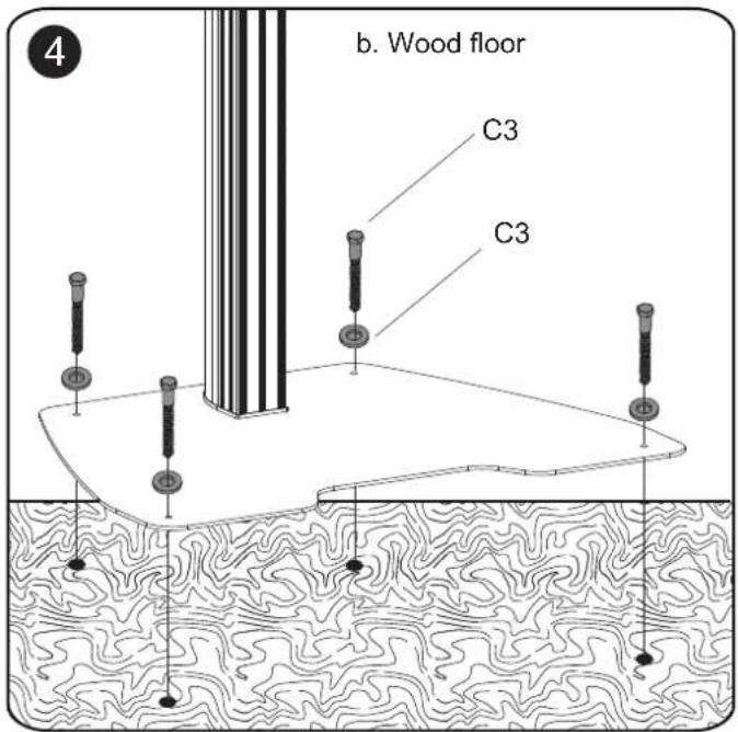
text_image
b. Wood floor C3 C3
text_image
5 B6 NOTES: B6 (NMPRO-S1) 4PCS each pillar B6 (NMPRO-S21) 4PCS each pillar B6 (NMPRO-S12) 8PCS each pillar B6 (NMPRO-S22) 8PCS each pillar B6 (NMPRO-S32) 8PCS each pillar B6 (NMPRO-S33) 12PCS each pillar NOTES: Mark the lines in same height on the pillar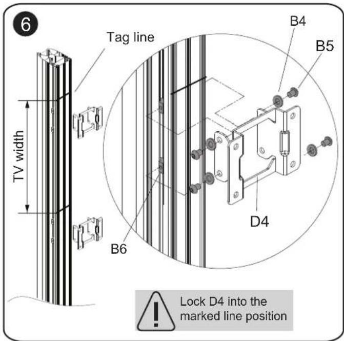
text_image
6 TV width Tag line B4 B5 D4 B6 Lock D4 into the marked line position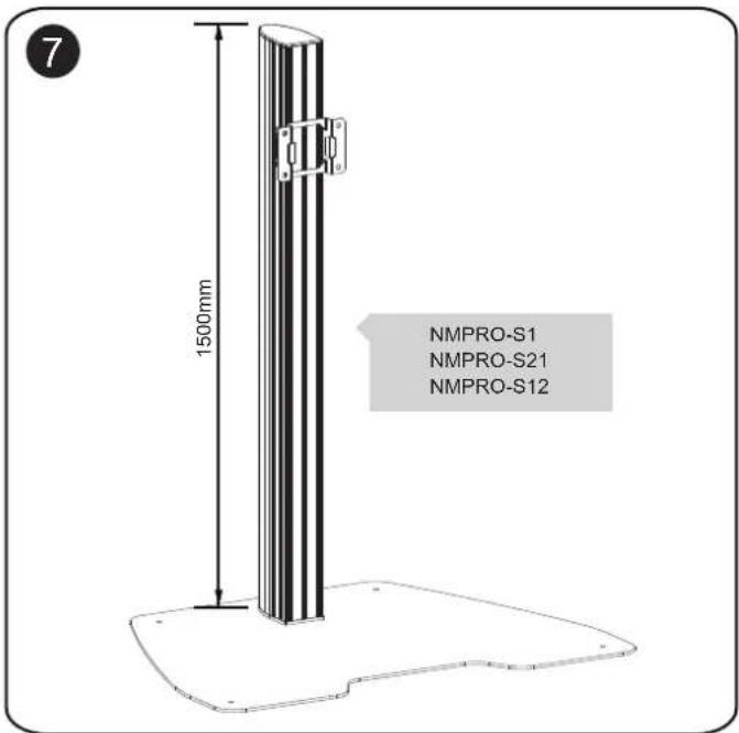
text_image
7 1500mm NMPRO-S1 NMPRO-S21 NMPRO-S12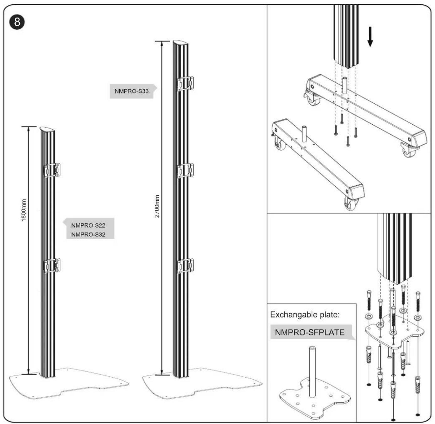
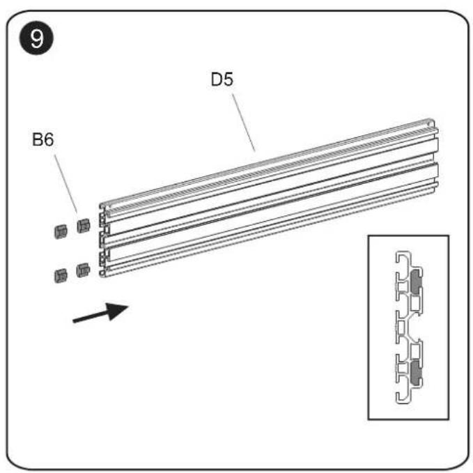
text_image
9 B6 D5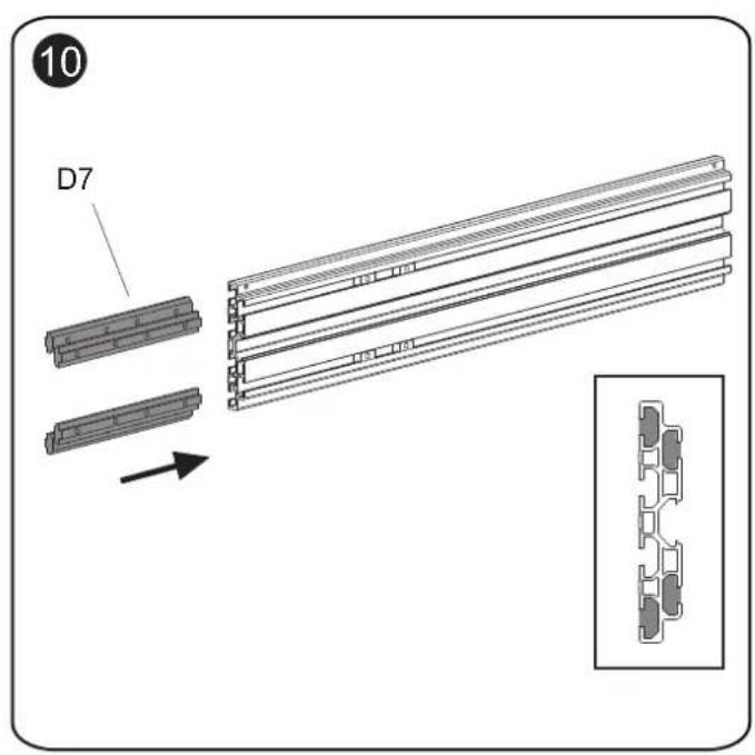
text_image
10 D7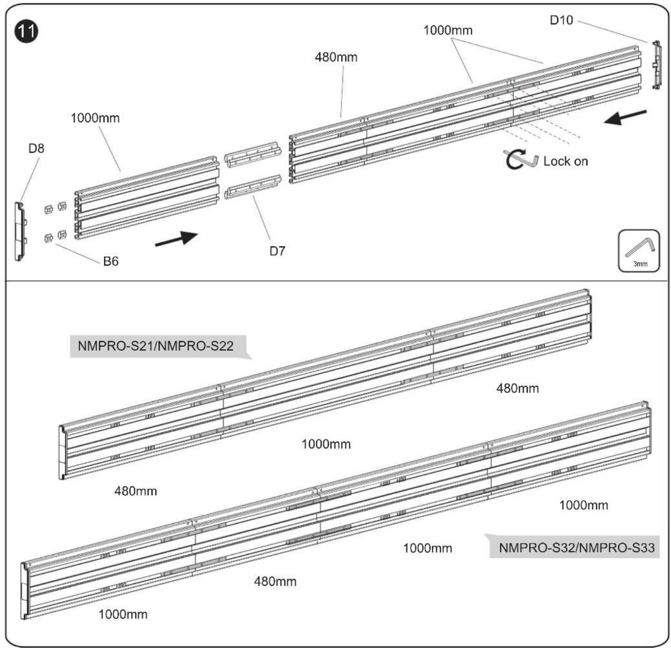
text_image
11 D8 1000mm B6 480mm 1000mm D7 1000mm D10 Lock on 3mm NMPRO-S21/NMPRO-S22 480mm 1000mm 480mm 1000mm 480mm 1000mm NMPRO-S32/NMPRO-S33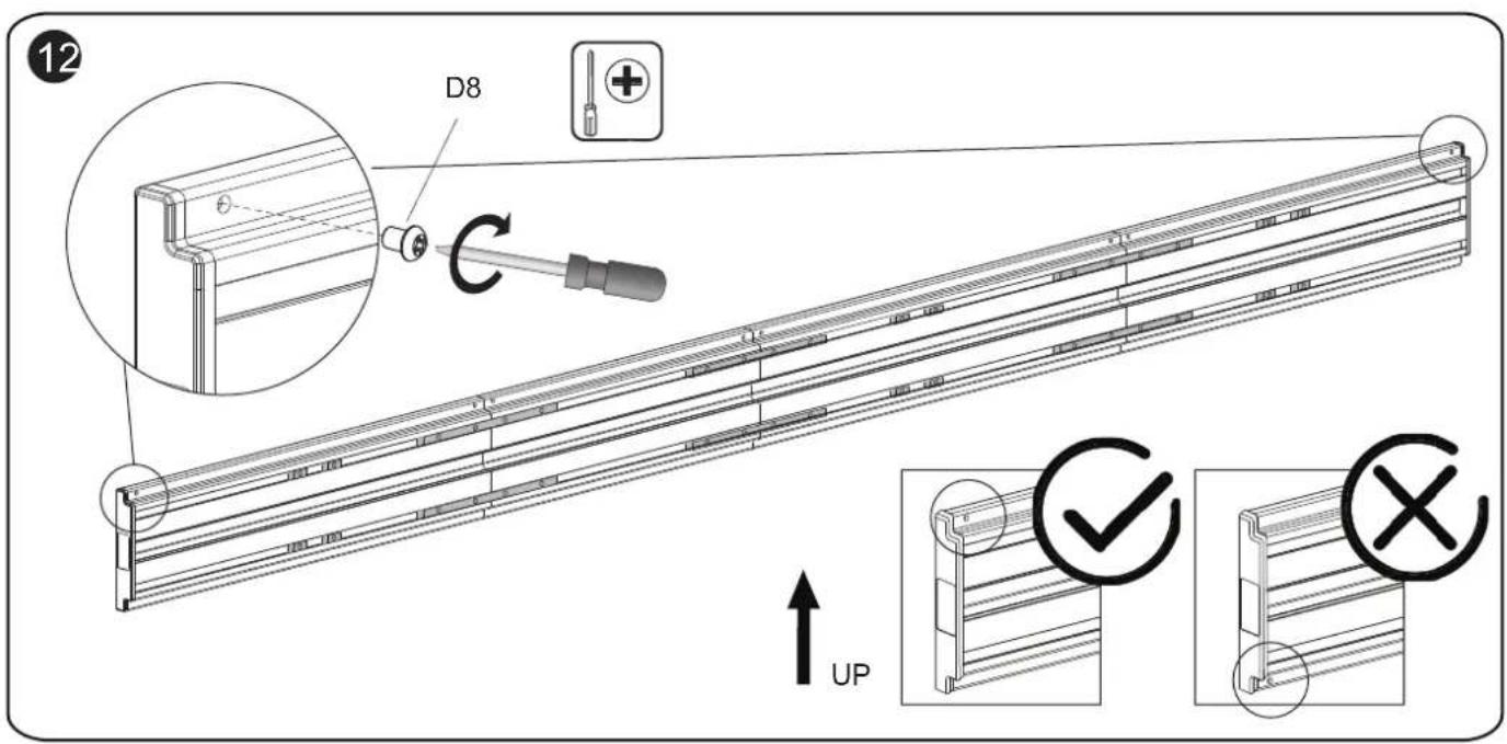
text_image
12 D8 ↑UP ✓ ×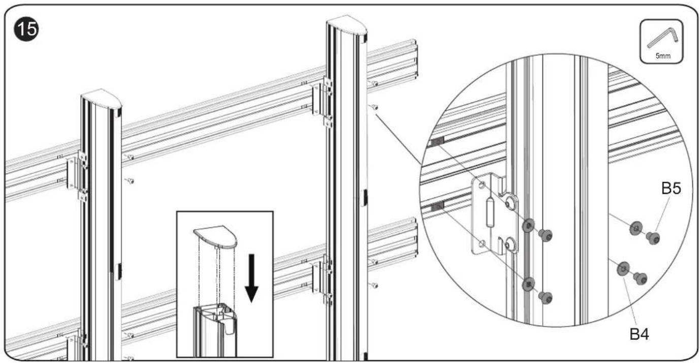
text_image
15 5mm B5 B4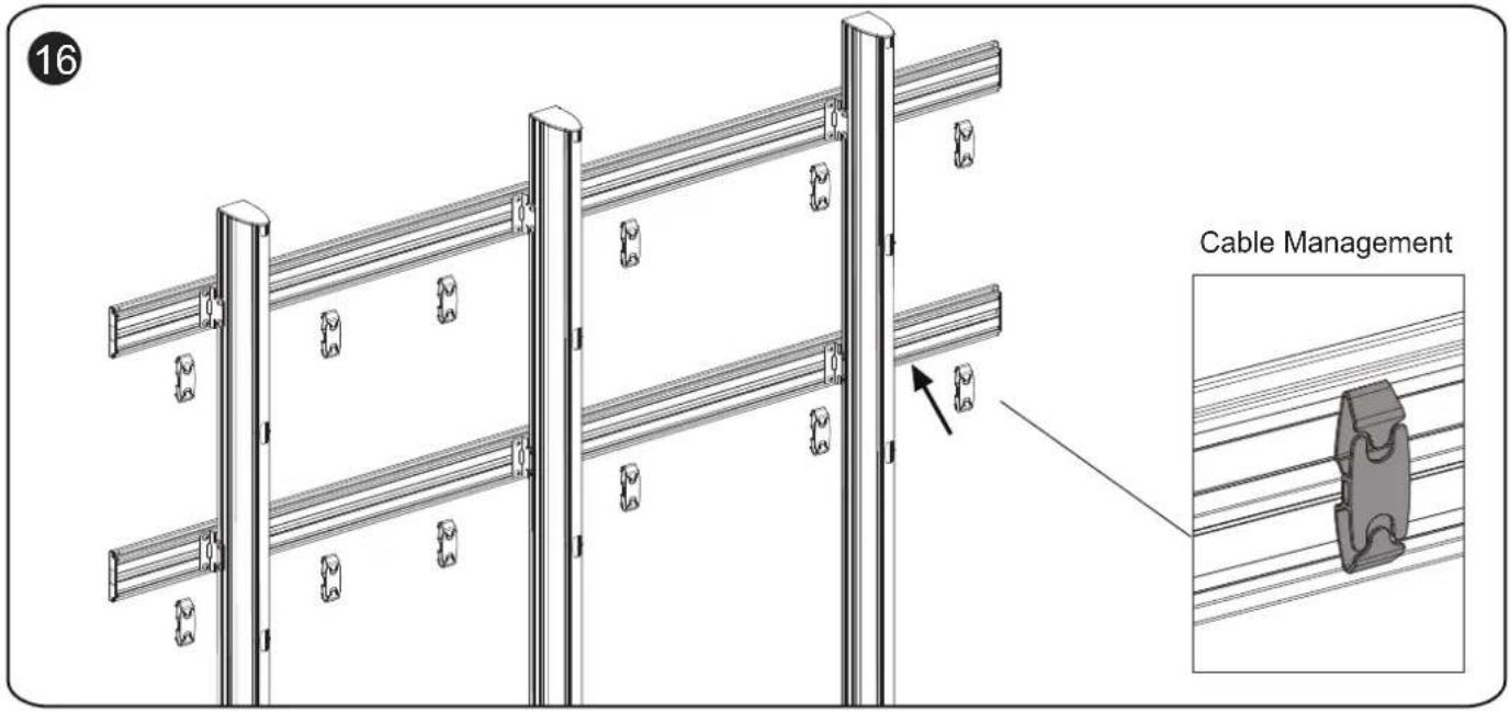
text_image
16 Cable Management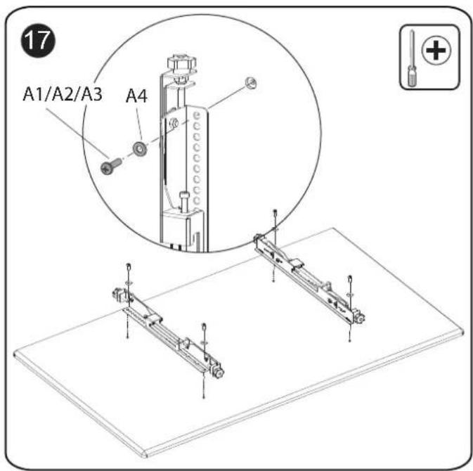
text_image
17 A1/A2/A3 A4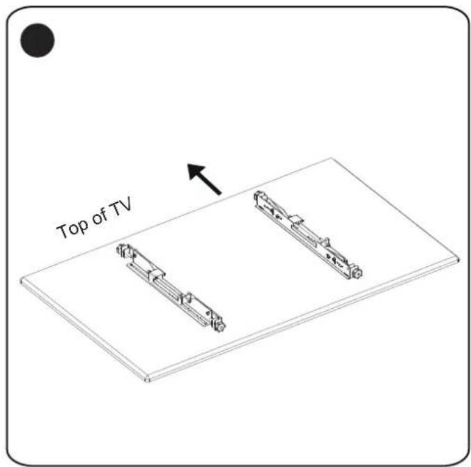
text_image
Top of TV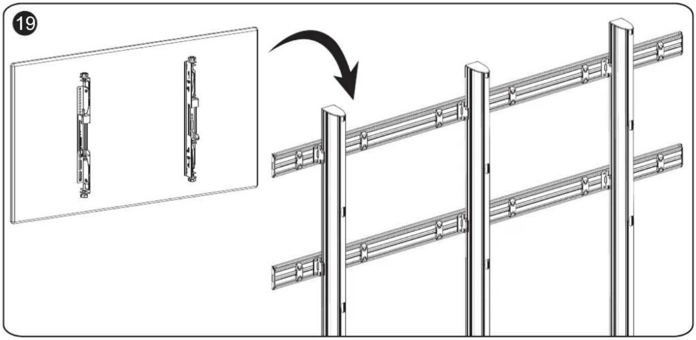
text_image
Technical diagram showing assembly steps of a metal fence with labeled components and a directional arrow indicating process.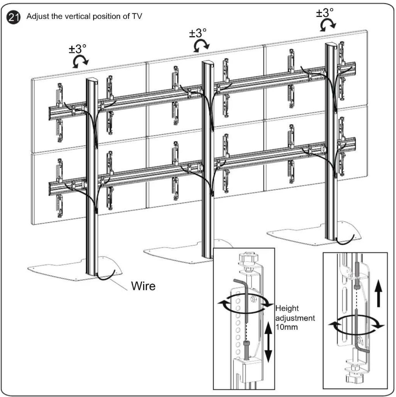
text_image
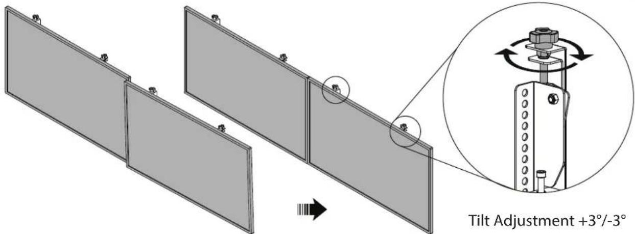
21 Adjust the vertical position of TV ±3° ±3° ±3° Wire Height adjustment 10mm21
natural_image
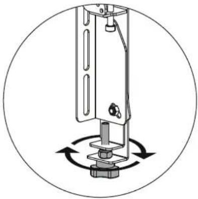
Mechanical assembly diagram showing a rotating component with arrows indicating rotational motion (no text or symbols)23
text_image
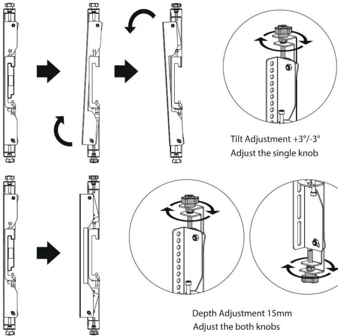
Tilt Adjustment +3°/-3°