
AV30-500BL - Uncategorized NeoMounts - Free user manual and instructions
Find the device manual for free AV30-500BL NeoMounts in PDF.


| Product Type | Universal Videobar Mount |
| Compatible Videobar Models | Bose Professional VB1, Neat Bar (gen 1), Neat Bar Pro, Poly Studio USB, Poly Studio X50/X52/V52, Poly Studio X70/X72/V72, Jabra Panacast 50, Jabra Panacast 40, Logitech Meetup, Cisco Webex Room Kit Plus, Yealink MSpeaker II, Yealink MeetingBar A40/A50, AVer VB350/VB370A, Barco ClickShare Bar (Pro), Logitech Rally Bar/Mini/Huddle, Maxhub Xbar W70/U50/V50, Bose Professional VB-S, Logitech Meetup 2, Poly Studio V12/X30/X32/R30, Yealink UVC20/UVC40/UVC34/MeetingBar A30/MeetingEye 400/600, Maxhub UC S05/S07/S10/S10 Pro/S15, Logitech Rally Plus, Yealink UVC30 Room, Predia Connect Camera, biamp Parlé VBC 2800/VBC 2500(a)/ABC 2500(a), biamp Parlé SBC 2, Lenovo ThinkSmart One, and more |
| Mounting Orientation | Above or below screen |
| VESA Compatibility | Horizontal: 200, 400, 600, 800 mm; Vertical: adjustable via plates (P) |
| Maximum Extension | 84 cm (with extension brackets S, R) |
| Minimum Profile Depth | 35 mm |
| Height Adjustment | Yes, via bracket (Q) sliding on vertical bars (T) |
| Weight Capacity | Approximately 20 kg (44 lbs) |
| Material | Steel, powder-coated |
| Color | Black |
| Included Accessories | Brackets (O, Q, P), vertical bars (T), extension brackets (S, R), universal mounting brackets (U, V, W, X, Y, Z), screws, locking screws, instruction manual |
| Installation | Requires wall/floor mount (not included); screen brackets not included; professional installation recommended |
| Safety | Mount must support at least 4x combined weight; do not install near heat, moisture, or vibration; use at least two persons for installation |
| Warranty | 5 years on mount body |
Frequently Asked Questions - AV30-500BL NeoMounts
User questions about AV30-500BL NeoMounts
0 question about this device. Answer the ones you know or ask your own.
Ask a new question about this device
Download the instructions for your Uncategorized in PDF format for free! Find your manual AV30-500BL - NeoMounts and take your electronic device back in hand. On this page are published all the documents necessary for the use of your device. AV30-500BL by NeoMounts.
USER MANUAL AV30-500BL NeoMounts


T. (×2)

U. (x1)

V. (×1)

W. (x2)

X. (x1)

Y. x1
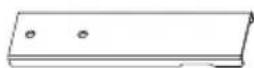
Z. x2
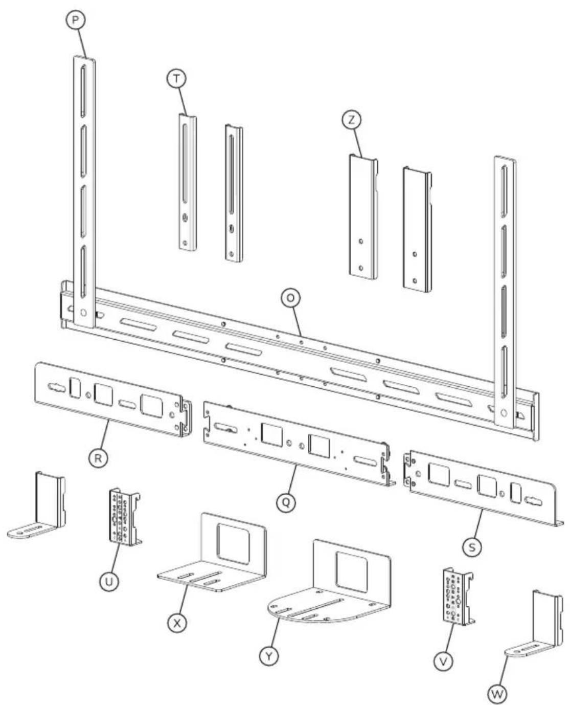
STEP 1
EN Determine whether the videobar should be mounted above or below the screen and continue with the corresponding instruction steps in the manual
NL Bepaal of de videobar boven of onder het scherm moet worden gemonteerd en ga verder met de bijbehorende instructiestappen in de handleiding
DE Bestimmen Sie, ob die Videobar oberhalb oder unterhalb des Bildschirms montiert werden soll, und fahren Sie mit den entsprechenden Anleitungsschritten im Manual fort
FR Déterminez si la barre vidéo doit être montée au-dessus ou au-dessous de l'écran et poursuivez avec les étapes d'instruction correspondantes dans le manuel
IT Determinare se la barra video deve essere montata al di sopra o al di sotto dello schermo e proseguire con le relative fasi di istruzione del manuale
ES Determine si la barra de vídeo debe montarse encima o debajo de la pantalla y continúe con los pasos de instrucción correspondientes del manual
PT Determine se a barra de vídeo deve ser montada por cima ou por baixo do ecrã e continue com os passos de instrução correspondentes no manual
PL Określ, czy listwa wideo powinna być zamontowana nad czy pod ekranem, a następnie postępuj zgodnie z odpowiednimi instrukcjami w podręczniku
STEP 2-31 Below screen

STEP 32-61 Above screen

STEP 2 Below screen
EN Determine the horizontal VESA dimension of the screen
EN Disconnect the vertical mounting plates (P) from the bracket (O)
STEP 4 Below screen
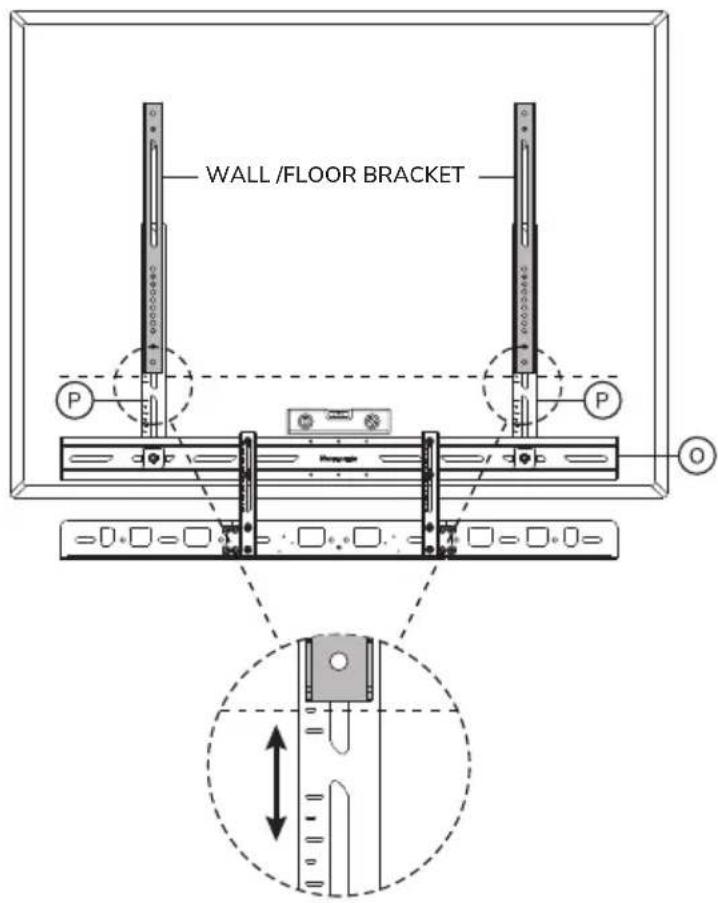
EN Align the vertical mounting plates (P) with the horizontal VESA of the screen
NL Lijn de verticale bevestigingsplaten (P) uit met de horizontale VESA van het scherm
DE Richten Sie die vertikalen Montageplatten (P) an der horizontalen VESA des Bildschirms aus
FR Aligner les plaques de montage verticales (P) avec les plaques VESA horizontales de l'écran
IT Allineare le piastre di montaggio verticali (P) con il VESA orizzontale dello schermo
ES Alinee las placas de montaje verticales (P) con el VESA horizontal de la pantalla
PT Alinhar as placas de montagem verticais (P) com a VESA horizontal do ecrã
PL Wyrównaj pionowe płytki montażowe (P) z poziomymi płytkami VESA ekranu

STEP 5 Below screen
EN Install the vertical mounting plates (P) in the correct position onto the bracket (O)
NL Installeer de verticale bevestigingsplaten (P) in de juiste positie op de beugel (O)
DE Montieren Sie die vertikalen Montageplatten (P) in der richtigen Position an der Halterung (O)
FR Installer les plaques de montage verticales (P) dans la position correcte sur le support (O)
IT Installare le piastre di montaggio verticali (P) nella posizione corretta sulla staffa (O)
ES Instale las placas de montaje verticales (P) en la posición correcta en el soporte (O)
PT Instalar as placas de montagem vertical (P) na posição correcta no suporte (O)
PL Zamontować pionowe płyty montażowe (P) we właściwej pozycji do wspornika (O)

STEP 6 Below screen
EN Attach the bracket (Q) to the vertical bars (T)
STEP 7 Below screen
EN Move the bracket (Q) to the lowest position
OPTION Below screen
EN Attach the extension brackets (S, R) if needed
NL Bevestig de verlengbeugels (S, R) indien nodig
DE Befestigen Sie die Verlängerungshalterungen (S, R), falls erforderlich
FR Fixez les supports d'extension (S, R) si nécessaire
IT Fissa le staffe di estensione (S. R) se necessario
ES Fije los soportes de extensión (S, R) si es necesario
PT Prenda os suportes de extensão (S, R) se necessário
PL Przymocuj wsporniki przedłużające (S, R), jeśli to konieczne

Note: Extension parts to be used when device connection is more than 30.8 cm

STEP 8 Below screen
EN Determine the vertical position of the videobar mount on the screen. The bracket (O) should be approx. 5 cm above the bottom of the screen
NL Bepaal de verticale positie van de videobarbeugel op het scherm. De beugel (O) moet circa 5 cm boven de onderzijde van het scherm zitten
DE Bestimmen Sie die vertikale Position der Videobar-Halterung auf dem Bildschirm. Die Halterung (O) sollte sich ca. 5 cm über der Unterseite des Bildschirms befinden
FR Déterminez la position verticale du support de la barre vidéo sur l'écran. Le support (O) doit se trouver à environ 5 cm au-dessus du bas de l'écran
IT Determinare la posizione verticale della staffa della barra video sullo schermo. La staffa (O) deve trovarsi a circa 5 cm sopra della parte inferiore dello schermo
ES Determine la posición vertical del soporte de la barra de vídeo en la pantalla. El soporte (O) debe estar aproximadamente 5 cm por encima de la parte inferior de la pantalla
PT Determine a posição vertical do suporte da barra de vídeo no ecrã. O suporte (O) deve ficar aproximadamente 5 cm acima da parte inferior do ecrã
PL Określ pionowe położenie uchwytu paska wideo na ekranie. Uchwyt (O) powinien znajdować się około 5 cm nad dolną krawędzia ekranu
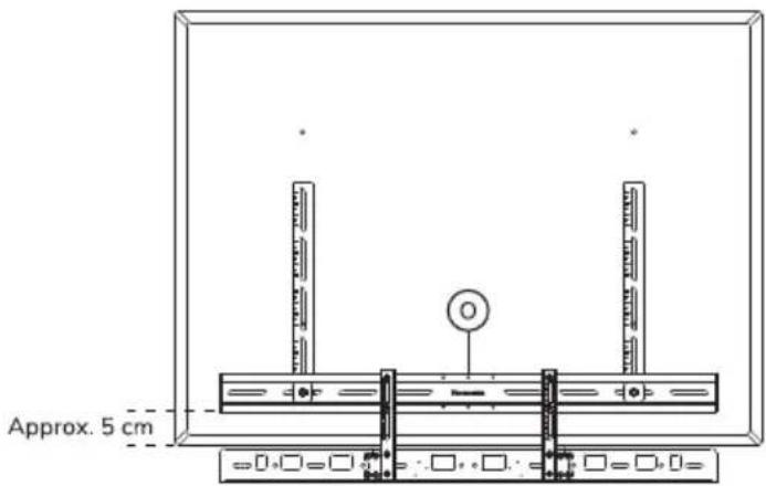
EN Attach the videobar mount to the screen and level horizontally
NL Bevestig de videobarbeugel aan het scherm en lijn horizontaal uit
DE Befestigen Sie die Videobar-Halterung am Bildschirm und richten Sie sie horizontal aus
FR Fixez le support de la barre vidéo à l'écran et alignez-le horizontalement
IT Fissare la staffa della barra video allo schermo e allinearla orizzontalmente
ES Fije el soporte de la barra de vídeo a la pantalla y alinéelo horizontalmente
PT Fixe o suporte da barra de vídeo ao ecrã e alinhe-o horizontalmente
PL Przymocuj wspornik paska wideo do ekranu i wyrównaj w poziomie
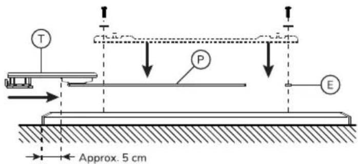

Place the screen on a flat surface, using protective material to prevent damage.

Note:
Screen brackets are not included. Follow the installation instructions included with the wall/floor mount.
STEP 10 Below screen
EN Select the relevant model and go to the corresponding instruction step
NL Selecteer het relevante model en ga naar de bijbehorende instructiestap
DE Wählen Sie das entsprechende Modell und gehen Sie zum entsprechenden Anweisungsschritt
FR Sélectionnez le modèle approprié et passez à l'étape d'instruction correspondante
IT Selezionare il modello in questione e passare alla fase di istruzione corrispondente
ES Seleccione el modelo pertinente y vaya al paso de instrucciones correspondiente
PT Selecionar o modelo relevante e passar ao passo de instrução correspondente
PL Wybierz odpowiedni model i przejdź do odpowiedniego kroku instrukcji
Select videobar model
Bose Professional VB1
Neat Bar (gen 1)*
Neat Bar Pro*
Poly Studio USB
Poly Studio X50/X52/V52
Poly Studio X70/X72/V72
Jabra Panacast 50
Jabra Panacast 40*
Logitech Meetup*
Cisco Webex Room Kit Plus
Yealink MSpeaker II*
Yealink MeetingBar A40*
Yealink MeetingBar A50*
AVer VB350*
AVer VB370A*
Barco ClickShare Bar (Pro)*
Parts to use

U. (x1)

V. (x1)
Instruction step
STEP 11-13
Logitech Rally Bar
Logitech Rally Bar Mini
Logitech Rally Bar Huddle
Maxhub Xbar W70
Maxhub Xbar U50/V50

U. (×1)

V. (x1)
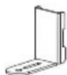
W. (×2)
STEP 14-16
Bose Professional VB-S
Logitech Meetup 2
Poly Studio V12
Poly Studio X30/X32
Poly Studio R30
Yeanlink UVC20
Yealink UVC40
Yealink UVC34
Yealink MeetingBar A30
Yealink MeetingEye 400
Yealink MeetingEye 600
Maxhub UC S05
Maxhub UC S07
Maxhub UC S10
Maxhub UC S10 Pro
Maxhub UC S15

T. x2

U. x1

V. (x1)

X. (×1)
STEP 17-19
| Select videobar model | Parts to use | Instruction step |
| Logitech Rally Plus |  G4A7 G4A7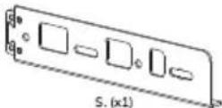  [Z046] [Z046] U.(x1)V.(x1)Y.(x1) U.(x1)V.(x1)Y.(x1) |  |
| Yealink UVC30 RoomPredia Connect CameraSmall VC camera's | 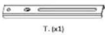  |  |
| biamp Parlé VBC 2800biamp Parlé VBC 2500(a)biamp Parlé ABC 2500(a) |  |  |
| biamp Parlé SBC 2Lenovo ThinkSmart One* |    [2064] [2064] U.(x1)V.(x1) U.(x1)V.(x1) |  |
Note:
If your device is not listed, check the Neomounts website for any updated versions of the manual.
Use the technical line drawings to determine if your product is compatible with the included universal brackets (U, V, W, X,Y).
* Requires mounting plate supplied with the device itself.
STEP 11 Below screen
EN Determine the correct hole pattern for the videobar model
NL Bepaal het juiste gatenpatroon voor het model videobar
DE Bestimmen Sie das richtige Lochmuster für das Videobar-Modell
FR Déterminer le schéma de perçage correct pour le modèle de vidéobar
IT Determinare la corretta disposizione dei fori per il modello di videobar
ES Determine el patrón de orificios correcto para el modelo de videobar
PT Determinar o padrão de orifícios correto para o modelo de barra de vídeo
PL Określenie prawidłowego układu otworów dla modelu wideobaru
Neat Bar (gen 1)
Neat Bar Pro*
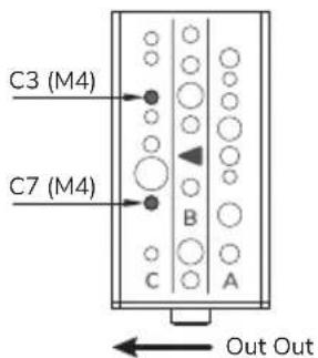
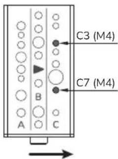
Poly Studio USB
Poly Studio X50 / X52 / V52
Poly Studio X70 / X72 / V72

Cisco Webex Room Kit Plus
Jabra PanaCast 50

AVer VB350*
AVer VB370A*
Yealink MeetingBar A40*
Yealink MeetingBar A50*
Barco ClickShare Bar (Pro)*
Jabra PanaCast 40*

Bose Professional VB1


Logitech Meetup*

Yealink MSpeaker II*

STEP 12 Below screen
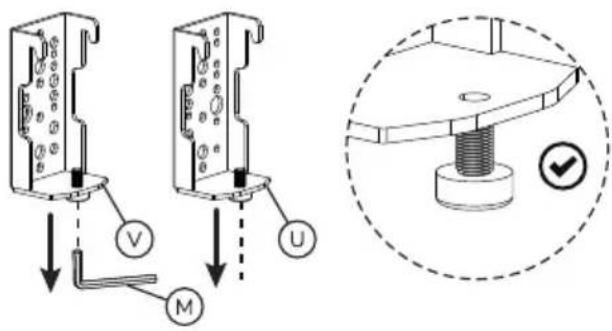
EN Loosen the locking screws and attach U and V to the videobar
NL Draai de borgschroeven los en bevestig U en V aan de videobar
DE Lösen Sie die Feststellschrauben und befestigen Sie Q und R an die Videobar
FR Desserrez les vis de verrouillage et fixez U et V au vidéobar
IT Allentare le viti di bloccaggio e fissare U e V al videobar
ES Afloje los tornillos de bloqueo y fije U y V al videobar
PT Desapertar os parafusos de bloqueio e fixar U e V na barra de vídeo
PL Poluzuj śruby blokujące i przymocuj U i V do wideobaru


STEP 13 Below screen
EN Attach the videobar to the bracket and secure it
NL Bevestig de videobar aan de beugel en zet deze vast
DE Befestigen Sie die Videobar an der Halterung und sichern Sie sie
FR Fixer le vidéobar au support et le sécuriser
IT Fissare la videobar alla staffa e fissarla
ES Coloca el videobar en el soporte y fijalo
PT Fixar a barra de vídeo no suporte e fixá-la
PL Przymocuj wideobar do uchwytu i zabezpiecz go

Continue to step 31 to complete the installation
STEP 14 Below screen
EN Loosen the locking screws and attach W (x2) to U and V

STEP 15 Below screen
EN Attach the combination to the videobar
STEP 16 Below screen
EN Attach the videobar to the bracket and secure it
NL Bevestig de videobar aan de beugel en zet deze vast
DE Befestigen Sie die Videobar an der Halterung und sichern Sie sie
FR Fixer le vidéobar au support et le sécuriser
IT Fissare la videobar alla staffa e fissarla
ES Coloca el videobar en el soporte y fijalo
PT Fixar a barra de vídeo no suporte e fixá-la
PL Przymocuj wideobar do uchwytu i zabezpiecz go

Continue to step 31 to complete the installation
STEP 17 Below screen
EN Loosen the locking screws and attach X to U and V
NL Draai de borgschroeven los en bevestig X aan U en V
DE Lösen Sie die Sicherungsschrauben und befestigen Sie X an U und V
FR Desserrez les vis de blocage et fixez X à U et V
IT Allentare le viti di bloccaggio e fissare X a U e V
ES Afloje los tornillos de fijación y fije X a U y V
PT Desaperte os parafusos de fixação e prenda X a U e V
PL Poluzuj śruby blokujące i przymocuj X do U i V
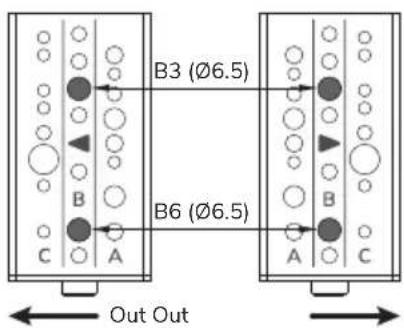


STEP 18 A Below screen
EN Attach the combination to the videobar
NL Bevestig de combinatie aan de videobar
DE Befestigen Sie die Kombination an die Videobar
FR Fixer la combinaison au vidéobar
IT Fissare la combinazione al videobar
ES Fije la combinación al videobar
PT Fixar a combinação à barra de vídeo
PL Przymocuj kombinację do wideobaru
Bose Professional VB-S Maxhub UC S05
Poly Studio Maxhub UC S07
Poly Studio X30/X32 Maxhub UC S10
Poly Studio R30 Maxhub UC S10 Pro
Yealink UVC34 Maxhub UC S15

STEP 18 B Below screen
EN Attach the combination to the videobar
NL Bevestig de combinatie aan de videobar
DE Befestigen Sie die Kombination an die Videobar
FR Fixer la combinaison au vidéobar
IT Fissare la combinazione al videobar
ES Fije la combinación al videobar
PT Fixar a combinação à barra de vídeo
PL Przymocuj kombinację do wideobaru
Yealink UVC40
Yealink MeetingBar A30
Yealink MeetingEye 400
Yealink MeetingEye 600

STEP 19 Below screen
EN Attach the videobar to the bracket and secure it
NL Bevestig de videobar aan de beugel en zet deze vast
DE Befestigen Sie die Videobar an der Halterung und sichern Sie sie
FR Fixer le vidéobar au support et le sécuriser
IT Fissare la videobar alla staffa e fissarla
ES Coloca el videobar en el soporte y fijalo
PT Fixar a barra de vídeo no suporte e fixá-la
PL Przymocuj wideobar do uchwytu i zabezpiecz go
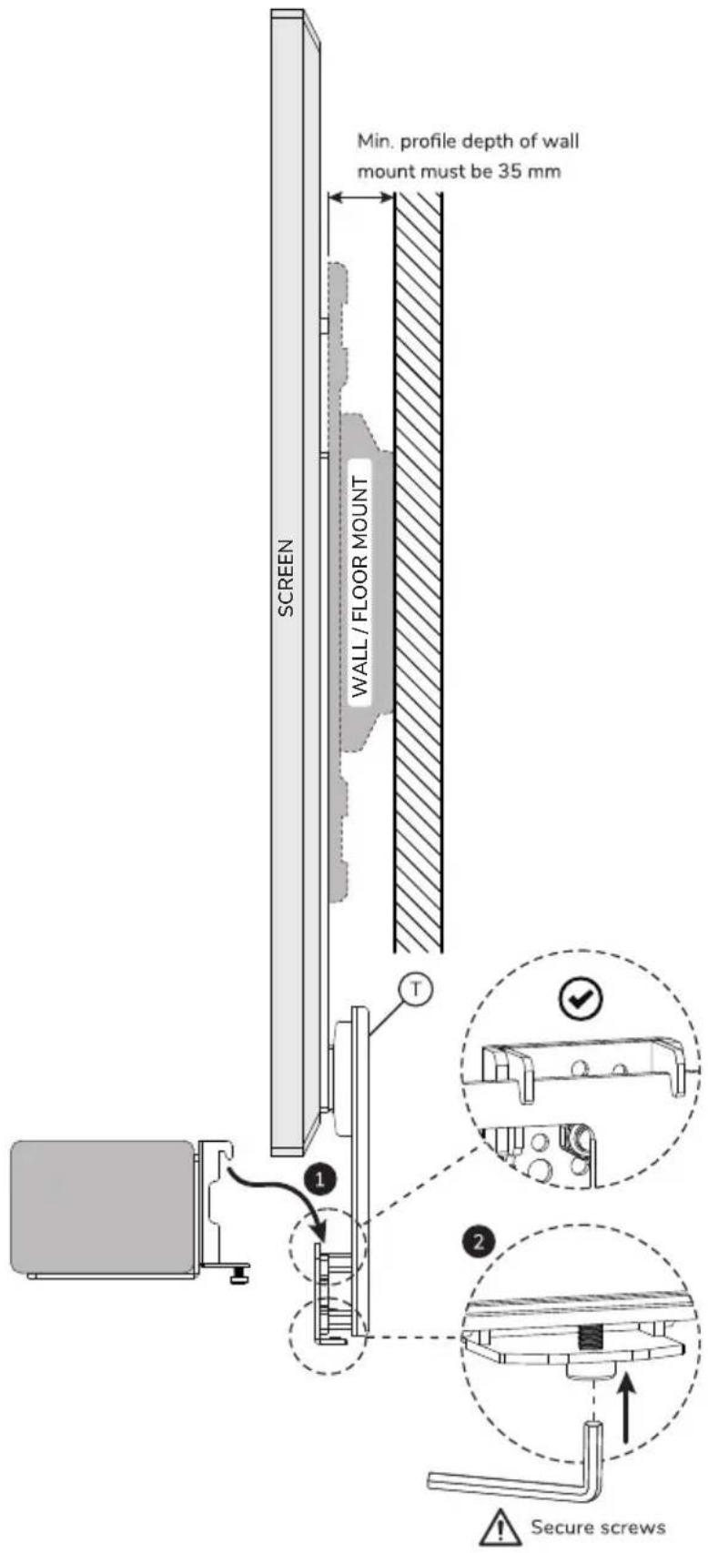
Continue to step 31 to complete the installation
OPTION Below screen
EN Attach X to the vertical bars (T) and mount the combination to the horizontal bar (O)
NL Bevestig X aan de verticale stangen (T) en monteer de combinatie aan de horizontale stang (O)
DE Befestigen Sie X an den vertikalen Stangen (T) und montieren Sie die Kombination an der horizontalen Stange (O)
FR Fixez X aux barres verticales (T) et montez l'ensemble sur la barre horizontale (O)
IT Fissare X alle barre verticali (T) e montare il tutto sulla barra orizzontale (O)
ES Fije X a las barras verticales (T) y monte la combinación en la barra horizontal (O)
PT Fixar X às barras verticais (T) e montar a combinação na barra horizontal (O)
PL Przymocuj X do pionowych prętów (T) i zamontuj zestaw do poziomego pręta (O)

STEP 20 Below screen
EN Attach the speakers to the bracket and secure them
NL Bevestig de luidsprekers aan de beugel en zet deze vast
DE Befestigen Sie die Lautsprecher an der Halterung und sichern Sie sie
FR Fixer les haut-parleurs au support et les sécuriser
IT Fissare gli altoparlanti alla staffa e fissarli
ES Coloca los altavoces en el soporte y asegúrelos
PT Fixar os altifalantes no suporte e fixe-os
PL Przymocuj głośniki do uchwytu i zamocuj je
Logitech Rally Speakers


STEP 21 Below screen
EN Loosen the locking screws, install U and V to Z and attach Y to Z
NL Draai de borgschroeven los, bevestig U en V aan Z en mon-
teer Y aan Z
DE Lösen Sie die Verriegelungsschrauben, montieren Sie U und V an Z und befestigen Sie Y an Z
FR Desserrez les vis de verrouillage, installez U et V sur Z et fixez Y à Z
IT Allentare le viti di bloccaggio, installare U e V su Z e fissare Y a Z
ES Afloje los tornillos de bloqueo, instale U y V en Z y fije Y a Z
PT Desapertar os parafusos de fixação, instalar U e V em Z e fixar Y em Z
PL Poluzuj śruby blokujące, zamontuj U i V do Z i przymocuj Y do Z

Logitech Rally Plus


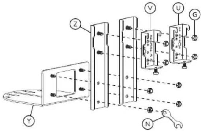

STEP 22 Below screen
EN Attach the speakers to the bracket and secure them
NL Bevestig de luidsprekers aan de beugel en zet deze vast
DE Befestigen Sie die Lautsprecher an der Halterung und sichern Sie sie
FR Fixer les haut-parleurs au support et les sécuriser
IT Fissare gli altoparlanti alla staffa e fissarli
ES Coloca los altavoces en el soporte y asegúrelos
PT Fixar os altifalantes no suporte e fixe-os
PL Przymocuj głośniki do uchwytu i zamocuj je


STEP 23 Below screen
EN Attach the camera to the bracket and secure it
NL Bevestig de camera aan de beugel en zet deze vast
DE Befestigen Sie die Kamera an der Halterung und sichern Sie sie
FR Fixer la caméra au support et la sécuriser
IT Fissare la videocamera alla staffa e fissarla
ES Coloca la cámara en el soporte y fijalo
PT Fixar a câmara no suporte e fixá-la
PL Przymocuj kamerę do uchwytu i zabezpiecz go
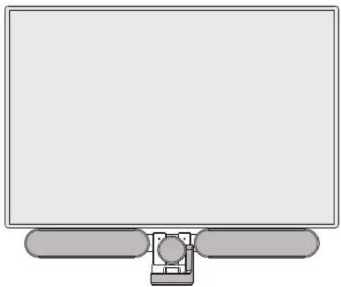

OPTION Below screen
EN Attach Y to the vertical bars (T) and mount the combination to the horizontal bar (O)
NL Bevestig Y aan de verticale stangen (T) en monteer de combinatie aan de horizontale stang (O)
DE Befestigen Sie Y an den vertikalen Stangen (T) und montieren Sie die Kombination an der horizontalen Stange (O)
FR Fixez Y aux barres verticales (T) et montez l'ensemble sur la barre horizontale (O)
IT Fissare Y alle barre verticali (T) e montare il tutto sulla barra orizzontale (O)
ES Fije Y a las barras verticales (T) y monte la combinación en la barra horizontal (O)
PT Fixar Y às barras verticais (T) e montar a combinação na barra horizontal (O)
PL Przymocuj Y do pionowych prętów (T) i zamontuj zestaw do poziomego pręta (O)

STEP 24 Below screen
EN Attach W to a vertical bar (T) and mount the combination to the horizontal bar (O)
NL Bevestig W aan een verticale stang (T) en monteer de combinatie aan de horizontale stang (O)
DE Befestigen Sie W an einer vertikalen Stange (T) und montieren ren Sie die Kombination an der horizontalen Stange (O)
FR Fixez W à une barre verticale (T) et montez l'ensemble sur la barre horizontale (O)
IT Fissare W a una barra verticale (T) e montare il tutto sulla barra orizzontale (O)
ES Fije W a una barra vertical (T) y monte la combinación en la barra horizontal (O)
PT Fixar W a uma barra vertical (T) e montar a combinação na barra horizontal (O)
PL Przymocuj W do pionowych belki (T) i zamontuj zestaw do poziomego pręta (O)


STEP 25 Below screen
EN Attach the camera to the bracket and secure it
NL Bevestig de camera aan de beugel en zet deze vast
DE Befestigen Sie die Kamera an der Halterung und sichern Sie sie
FR Fixer la caméra au support et la sécuriser
IT Fissare la videocamera alla staffa e fissarla
ES Coloca la cámara en el soporte y fijalo
PT Fixar a câmara no suporte e fixá-la
PL Przymocuj kamere do uchwytu i zabezpiecz go
Yealink UVC30 Room
Predia Connect Camera
Small VC camera's

STEP 26 Below screen
EN Attach the videobar to the bracket and secure it
NL Bevestig de videobar aan de beugel en zet deze vast
DE Befestigen Sie die Videobar an der Halterung und sichern Sie sie
FR Fixer le vidéobar au support et le sécuriser
IT Fissare la videobar alla staffa e fissarla
ES Coloca el videobar en el soporte y fijalo
PT Fixar a barra de vídeo no suporte e fixá-la
PL Przymocuj wideobar do uchwytu i zabezpiecz go
biamp Parlé VBC 2800
biamp Parlé VBC 2500(a)
biamp Parlé ABC 2500(a)


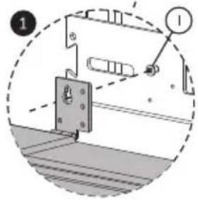
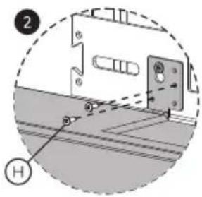
STEP 27 Below screen
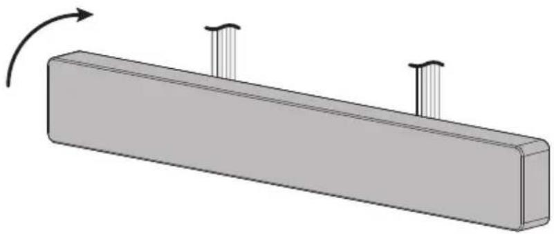
EN Attach the speakerbar to the bracket and secure it
NL Bevestig de speakerbar aan de beugel en zet deze vast
DE Befestigen Sie die Soundbar an der Halterung und sichern Sie sie
FR Fixer la barre de son au support et la sécuriser
IT Fissare la soundbar alla staffa e fissarla
ES Coloca la barra de sonido en el soporte y fijala
PT Fixar a barra de som no suporte e fixá-la
PL Przymocuj soundbar do uchwytu i zabezpiecz ją
biamp Parlé SBC 2



STEP 28 Below screen
EN Attach the videobar to the bracket and secure it
NL Bevestig de videobar aan de beugel en zet deze vast
DE Befestigen Sie die Videobar an der Halterung und sichern Sie sie
FR Fixer le vidéobar au support et le sécuriser
IT Fissare la videobar alla staffa e fissarla
ES Coloca el videobar en el soporte y fijalo
PT Fixar a barra de vídeo no suporte e fixá-la
PL Przymocuj wideobar do uchwytu i zabezpiecz go

Continue to step 31 to complete the installation
STEP 29 Below screen
EN Attach the videobar to the bracket and secure it
NL Bevestig de videobar aan de beugel en zet deze vast
DE Befestigen Sie die Videobar an der Halterung und sichern Sie sie
FR Fixer le vidéobar au support et le sécuriser
IT Fissare la videobar alla staffa e fissarla
ES Coloca el videobar en el soporte y fijalo
PT Fixar a barra de vídeo no suporte e fixá-la
PL Przymocuj wideobar do uchwytu i zabezpiecz go
Lenovo ThinkSmart One


STEP 30 Below screen
EN Attach the videobar to the bracket and secure it
NL Bevestig de videobar aan de beugel en zet deze vast
DE Befestigen Sie die Videobar an der Halterung und sichern Sie sie
FR Fixer le vidéobar au support et le sécuriser
IT Fissare la videobar alla staffa e fissarla
ES Coloca el videobar en el soporte y fijalo
PT Fixar a barra de vídeo no suporte e fixá-la
PL Przymocuj wideobar do uchwytu i zabezpiecz go
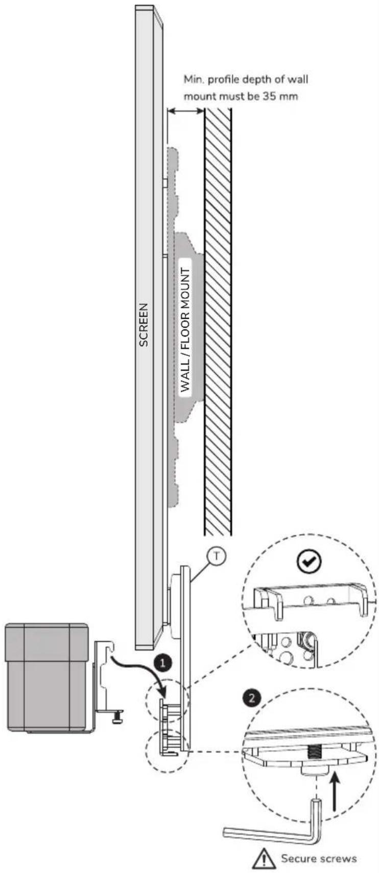
Continue to step 31 to complete the installation
STEP 31 Below screen
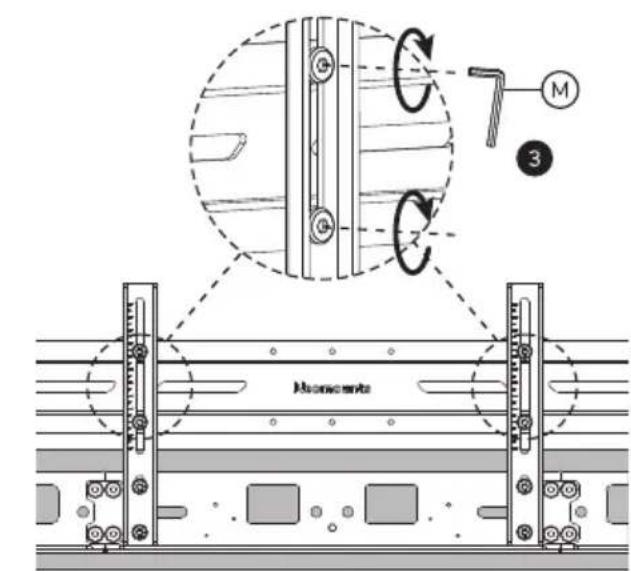
EN Adjust the height of the videobar to the desired position
NL Stel de hoogte van de videobar in op de gewenste positie
DE Stellen Sie die Höhe der Videobar auf die gewünschte Position ein
FR Ajuster la hauteur de la barre vidéo à la position souhaitée
IT Regolare l'altezza della videobar nella posizione desiderata
ES Ajuste la altura de la videobarra a la posición deseada
PT Ajustar a altura da barra de vídeo para a posição pretendida
PL Dostosuj wysokość paska wideo do żądanej pozycji


STEP 32 Above screen
EN Determine the horizontal VESA dimension of the screen
STEP 33 Above screen
EN Disconnect the vertical mounting plates (P) from the bracket (O)
STEP 34 Above screen
EN Align the vertical mounting plates (P) with the horizontal VESA of the screen
NL Lijn de verticale bevestigingsplaten (P) uit met de horizontale VESA van het scherm
DE Richten Sie die vertikalen Montageplatten (P) an der horizontalen VESA des Bildschirms aus
FR Aligner les plaques de montage verticales (P) avec les plaques VESA horizontales de l'écran
IT Allineare le piastre di montaggio verticali (P) con il VESA orizzontale dello schermo
ES Alinee las placas de montaje verticales (P) con el VESA horizontal de la pantalla
PT Alinhar as placas de montagem verticais (P) com a VESA horizontal do ecrã
PL Wyrównaj pionowe płytki montażowe (P) z poziomymi płytkami VESA ekranu

STEP 35 Above screen
EN Install the vertical mounting plates (P) in the correct position onto the bracket (O)
NL Installeer de verticale bevestigingsplaten (P) in de juiste positie op de beugel (O)
DE Montieren Sie die vertikalen Montageplatten (P) in der richtigen Position an der Halterung (O)
FR Installer les plaques de montage verticales (P) dans la position correcte sur le support (O)
IT Installare le piastre di montaggio verticali (P) nella posizione corretta sulla staffa (O)
ES Instale las placas de montaje verticales (P) en la posición correcta en el soporte (O)
PT Instalar as placas de montagem vertical (P) na posição correcta no suporte (O)
PL Zamontować pionowe płyty montażowe (P) we właściwej pozycji do wspornika (O)

STEP 36 Above screen
EN Attach the bracket (Q) to the vertical bars (T)
STEP 37 Above screen
EN Move the bracket (Q) to the highest position

OPTION Above screen
EN Attach the extension brackets (S, R) if needed
NL Bevestig de verlengbeugels (S, R) indien nodig
DE Befestigen Sie die Verlängerungshalterungen (S, R), falls erforderlich
FR Fixez les supports d'extension (S, R) si nécessaire
IT Fissa le staffe di estensione (S. R) se necessario
ES Fije los soportes de extensión (S, R) si es necesario
PT Prenda os suportes de extensão (S, R) se necessário
PL Przymocuj wsporniki przedłużające (S, R), jeśli to konieczne

Note: Extension parts to be used when device connection is more than 30.8 cm


STEP 38 Above screen
EN Determine the vertical position of the videobar mount on the screen. The bracket (O) should be approx. 5 cm below the top of the screen
NL Bepaal de verticale positie van de videobarbeugel op het scherm. De beugel (O) moet circa 5 cm onder de bovenkant van het scherm zitten
DE Bestimmen Sie die vertikale Position der Videobar-Halterung auf dem Bildschirm. Die Halterung (O) sollte sich ca. 5 cm über der Oberseite des Bildschirms befinden
FR Déterminez la position verticale du support de la barre vidéo sur l'écran. Le support (O) doit se trouver à environ 5 cm en dessous du haut de l'écran
IT Determinare la posizione verticale della staffa della barra video sullo schermo. La staffa (O) deve trovarsi a circa 5 cm al di sotto della parte superiore dello schermo
ES Determine la posición vertical del soporte de la barra de vídeo en la pantalla. El soporte (O) debe estar aproximadamente 5 cm por debajo de la parte superior de la pantalla
PT Determine a posição vertical do suporte da barra de vídeo no ecrã. O suporte (O) deve ficar aproximadamente 5 cm abaixo da parte superior do ecrã
PL Określ pionowe położenie uchwytu paska wideo na ekranie. Uchwyt (O) powinien znajdować się około 5 cm poniżej górnej krawędzi ekranu

STEP 39 Above screen
EN Attach the videobar mount to the screen and level horizontally
NL Bevestig de videobarbeugel aan het scherm en lijn horizontaal uit
DE Befestigen Sie die Videobar-Halterung am Bildschirm und richten Sie sie horizontal aus
FR Fixez le support de la barre vidéo à l'écran et alignez-le horizontalement
IT Fissare la staffa della barra video allo schermo e allinearla orizzontalmente
ES Fije el soporte de la barra de vídeo a la pantalla y alinéelo horizontalmente
PT Fixe o suporte da barra de vídeo ao ecrã e alinhe-o horizontalmente
PL Przymocuj wspornik paska wideo do ekranu i wyrównaj w poziomie

Place the screen on a flat surface, using protective material to prevent damage.
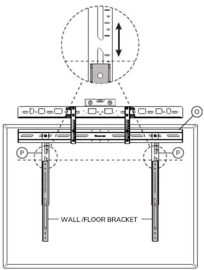

Note: Screen brackets are not included. Follow the installation instructions included with the wall/floor mount.
STEP 40 Above screen
EN Select the relevant model and go to the corresponding instruction step
NL Selecteer het relevante model en ga naar de bijbehorende instructiestap
DE Wählen Sie das entsprechende Modell und gehen Sie zum entsprechenden Anweisungsschritt
FR Sélectionnez le modèle approprié et passez à l'étape d'instruction correspondante
IT Selezionare il modello in questione e passare alla fase di istruzione corrispondente
ES Seleccione el modelo pertinente y vaya al paso de instrucciones correspondiente
PT Selecionar o modelo relevante e passar ao passo de instrução correspondente
PL Wybierz odpowiedni model i przejdź do odpowiedniego kroku instrukcji
Select videobar model
Bose Professional VB1
Neat Bar (gen 1) *
Neat Bar Pro*
Poly Studio USB
Poly Studio X50/X52/V52
Poly Studio X70/X72/V72
Jabra Panacast 50
Jabra Panacast 40*
Logitech Meetup*
Cisco Webex Room Kit Plus
Yealink MSpeaker II*
Yealink MeetingBar A40*
Yealink MeetingBar A50*
AVer VB350*
AVer VB370A*
Barco ClickShare Bar (Pro)*
Parts to use

U. (x1)

V. (x1)
Instruction step
STEP 41-43
Logitech Rally Bar
Logitech Rally Bar Mini
Logitech Rally Bar Huddle
Maxhub Xbar W70
Maxhub Xbar U50/V50

U. (×1)

V. (x1)
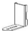
W. (×2)
STEP 44-46
Bose Professional VB-S
Logitech Meetup 2
Poly Studio V12
Poly Studio X30/X32
Poly Studio R30
Yeanlink UVC20
Yealink UVC40
Yealink UVC34
Yealink MeetingBar A30
Yealink MeetingEye 400
Yealink MeetingEye 600
Maxhub UC S05
Maxhub UC S07
Maxhub UC S10
Maxhub UC S10 Pro
Maxhub UC S15

T. x2

U. x1

V. (x1)
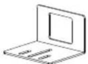
X. (×1)
STEP 47-49
| Select videobar model | Parts to use | Instruction step |
| Logitech Rally Plus |    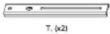  U. (x1) V. (x1) Y. (x1) U. (x1) V. (x1) Y. (x1) | STEP 50-53 |
| Yealink UVC30 Room Predia Connect Camera Small VC camera's |  T. (x1) [6D22] W. (x1) T. (x1) [6D22] W. (x1) | STEP 54-55 |
| biamp Parlé VBC 2800 biamp Parlé VBC 2500(a) biamp Parlé ABC 2500(a) |  | STEP 56 |
| biamp Parlé SBC 2 Lenovo ThinkSmart One* | Q. (x1) R. (x1) S. (x1) U. (x1) V. (x1) | STEP 57-60 |
Note:
If your device is not listed, check the Neomounts website for any updated versions of the manual.
Use the technical line drawings to determine if your product is compatible with the included universal brackets (U, V, W, X,Y).
* Requires mounting plate supplied with the device itself.
STEP 41 Above screen
EN Determine the correct hole pattern for the videobar model
NL Bepaal het juiste gatenpatroon voor het model videobar
DE Bestimmen Sie das richtige Lochmuster für das Videobar-Modell
FR Déterminer le schéma de perçage correct pour le modèle de vidéobar
IT Determinare la corretta disposizione dei fori per il modello di videobar
ES Determine el patrón de orificios correcto para el modelo de videobar
PT Determinar o padrão de orifícios correto para o modelo de barra de vídeo
PL Określenie prawidłowego układu otworów dla modelu wideobaru
Neat Bar (gen 1)
Neat Bar Pro*


Poly Studio USB
Poly Studio X50 / X52 / V52
Poly Studio X70 / X72 / V72

Cisco Webex Room Kit Plus
Jabra PanaCast 50

AVer VB350*
AVer VB370A*
Yealink MeetingBar A40*
Yealink MeetingBar A50*
Barco ClickShare Bar (Pro)*
Jabra PanaCast 40*

Bose Professional VB1


Logitech Meetup*

Yealink MSpeaker II*

STEP 42 Above screen
EN Loosen the locking screws and attach U and V to the videobar
NL Draai de borgschroeven los en bevestig U en V aan de videobar
DE Lösen Sie die Feststellschrauben und befestigen Sie Q und R an die Videobar
FR Desserrez les vis de verrouillage et fixez U et V au vidéobar
IT Allentare le viti di bloccaggio e fissare U e V al videobar
ES Afloje los tornillos de bloqueo y fije U y V al videobar
PT Desapertar os parafusos de bloqueio e fixar U e V na barra de vídeo
PL Poluzuj śruby blokujące i przymocuj U i V do wideobaru

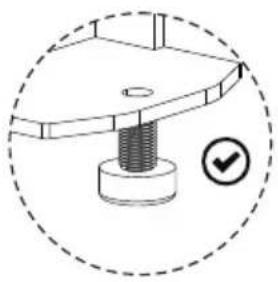

STEP 43 Above screen
EN Attach the videobar to the bracket and secure it
NL Bevestig de videobar aan de beugel en zet deze vast
DE Befestigen Sie die Videobar an der Halterung und sichern Sie sie
FR Fixer le vidéobar au support et le sécuriser
IT Fissare la videobar alla staffa e fissarla
ES Coloca el videobar en el soporte y fijalo
PT Fixar a barra de vídeo no suporte e fixá-la
PL Przymocuj wideobar do uchwytu i zabezpiecz go

STEP 44 Above screen
EN Loosen the locking screws and attach W (x2) to U and V

STEP 45 Above screen
EN Attach the combination to the videobar
STEP 46 Above screen
EN Attach the videobar to the bracket and secure it
NL Bevestig de videobar aan de beugel en zet deze vast
DE Befestigen Sie die Videobar an der Halterung und sichern Sie sie
FR Fixer le vidéobar au support et le sécuriser
IT Fissare la videobar alla staffa e fissarla
ES Coloca el videobar en el soporte y fijalo
PT Fixar a barra de vídeo no suporte e fixá-la
PL Przymocuj wideobar do uchwytu i zabezpiecz go

STEP 47 Above screen
EN Loosen the locking screws and attach X to U and V

STEP 48 A Above screen
EN Attach the combination to the videobar
Bose Professional VB-S Maxhub UC S05
Poly Studio Maxhub UC S07
Poly Studio X30/X32 Maxhub UC S10
Poly Studio R30 Maxhub UC S10 Pro
Yealink UVC34 Maxhub UC S15

STEP 48 B Above screen
EN Attach the combination to the videobar
STEP 49 Above screen
EN Attach the videobar to the bracket and secure it
NL Bevestig de videobar aan de beugel en zet deze vast
DE Befestigen Sie die Videobar an der Halterung und sichern Sie sie
FR Fixer le vidéobar au support et le sécuriser
IT Fissare la videobar alla staffa e fissarla
ES Coloca el videobar en el soporte y fijalo
PT Fixar a barra de vídeo no suporte e fixá-la
PL Przymocuj wideobar do uchwytu i zabezpiecz go

OPTION Above screen
EN Attach X to the vertical bars (T) and mount the combination to the horizontal bar (O)
NL Bevestig X aan de verticale stangen (T) en monteer de combinatie aan de horizontale stang (O)
DE Befestigen Sie X an den vertikalen Stangen (T) und montieren Sie die Kombination an der horizontalen Stange (O)
FR Fixez X aux barres verticales (T) et montez l'ensemble sur la barre horizontale (O)
IT Fissare X alle barre verticali (T) e montare il tutto sulla barra orizzontale (O)
ES Fije X a las barras verticales (T) y monte la combinación en la barra horizontal (O)
PT Fixar X às barras verticais (T) e montar a combinação na barra horizontal (O)
PL Przymocuj X do pionowych prętów (T) i zamontuj zestaw do poziomego pręta (O)


STEP 50 Above screen
EN Attach the speakers to the bracket and secure them
NL Bevestig de luidsprekers aan de beugel en zet deze vast
DE Befestigen Sie die Lautsprecher an der Halterung und sichern Sie sie
FR Fixer les haut-parleurs au support et les sécuriser
IT Fissare gli altoparlanti alla staffa e fissarli
ES Coloca los altavoces en el soporte y asegúrelos
PT Fixar os altifalantes no suporte e fixe-os
PL Przymocuj głośniki do uchwytu i zamocuj je
Logitech Rally Speakers


STEP 51 Above screen
EN Loosen the locking screws, install U and V to Z and attach Y to Z
NL Draai de borgschroeven los, bevestig U en V aan Z en mon-
teer Y aan Z
DE Lösen Sie die Verriegelungsschrauben, montieren Sie U und V an Z und befestigen Sie Y an Z
FR Desserrez les vis de verrouillage, installez U et V sur Z et fixez Y à Z
IT Allentare le viti di bloccaggio, installare U e V su Z e fissare Y a Z
ES Afloje los tornillos de bloqueo, instale U y V en Z y fije Y a Z
PT Desapertar os parafusos de fixação, instalar U e V em Z e fixar Y em Z
PL Poluzuj śruby blokujące, zamontuj U i V do Z i przymocuj Y do Z

Logitech Rally Plus


STEP 52 Above screen
EN Attach the speakers to the bracket and secure them
NL Bevestig de luidsprekers aan de beugel en zet deze vast
DE Befestigen Sie die Lautsprecher an der Halterung und sichern Sie sie
FR Fixer les haut-parleurs au support et les sécuriser
IT Fissare gli altoparlanti alla staffa e fissarli
ES Coloca los altavoces en el soporte y asegúrelos
PT Fixar os altifalantes no suporte e fixe-os
PL Przymocuj głośniki do uchwytu i zamocuj je

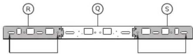
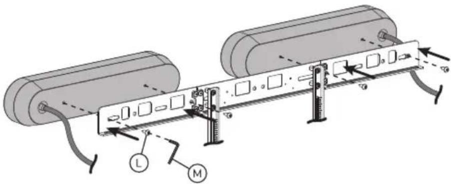
STEP 53 Above screen
EN Attach the camera to the bracket and secure it
NL Bevestig de camera aan de beugel en zet deze vast
DE Befestigen Sie die Kamera an der Halterung und sichern Sie sie
FR Fixer la caméra au support et la sécuriser
IT Fissare la videocamera alla staffa e fissarla
ES Coloca la cámara en el soporte y fijalo
PT Fixar a câmara no suporte e fixá-la
PL Przymocuj kamerę do uchwytu i zabezpiecz go


Continue to step 61 to complete the installation
OPTION Above screen
EN Attach Y to the vertical bars (T) and mount the combination to the horizontal bar (O)
NL Bevestig Y aan de verticale stangen (T) en monteer de combinatie aan de horizontale stang (O)
DE Befestigen Sie Y an den vertikalen Stangen (T) und montieren Sie die Kombination an der horizontalen Stange (O)
FR Fixez Y aux barres verticales (T) et montez l'ensemble sur la barre horizontale (O)
IT Fissare Y alle barre verticali (T) e montare il tutto sulla barra orizzontale (O)
ES Fije Y a las barras verticales (T) y monte la combinación en la barra horizontal (O)
PT Fixar Y às barras verticais (T) e montar a combinação na barra horizontal (O)
PL Przymocuj Y do pionowych prętów (T) i zamontuj zestaw do poziomego pręta (O)


STEP 54 Above screen
EN Attach W to a vertical bar (T) and mount the combination to the horizontal bar (O)
NL Bevestig W aan een verticale stang (T) en monteer de combinatie aan de horizontale stang (O)
DE Befestigen Sie W an einer vertikalen Stange (T) und montieren ren Sie die Kombination an der horizontalen Stange (O)
FR Fixez W à une barre verticale (T) et montez l'ensemble sur la barre horizontale (O)
IT Fissare W a una barra verticale (T) e montare il tutto sulla barra orizzontale (O)
ES Fije W a una barra vertical (T) y monte la combinación en la barra horizontal (O)
PT Fixar W a uma barra vertical (T) e montar a combinação na barra horizontal (O)
PL Przymocuj W do pionowych belki (T) i zamontuj zestaw do poziomego pręta (O)



STEP 55 Above screen
EN Attach the camera to the bracket and secure it
NL Bevestig de camera aan de beugel en zet deze vast
DE Befestigen Sie die Kamera an der Halterung und sichern Sie sie
FR Fixer la caméra au support et la sécuriser
IT Fissare la videocamera alla staffa e fissarla
ES Coloca la cámara en el soporte y fijalo
PT Fixar a câmara no suporte e fixá-la
PL Przymocuj kamerę do uchwytu i zabezpiecz go
Yealink UVC30 Room
Predia Connect Camera
Small VC camera's

STEP 56 Above screen
EN Attach the videobar to the bracket and secure it
NL Bevestig de videobar aan de beugel en zet deze vast
DE Befestigen Sie die Videobar an der Halterung und sichern Sie sie
FR Fixer le vidéobar au support et le sécuriser
IT Fissare la videobar alla staffa e fissarla
ES Coloca el videobar en el soporte y fijalo
PT Fixar a barra de vídeo no suporte e fixá-la
PL Przymocuj wideobar do uchwytu i zabezpiecz go
biamp Parlé VBC 2800
biamp Parlé VBC 2500(a)
biamp Parlé ABC 2500(a)
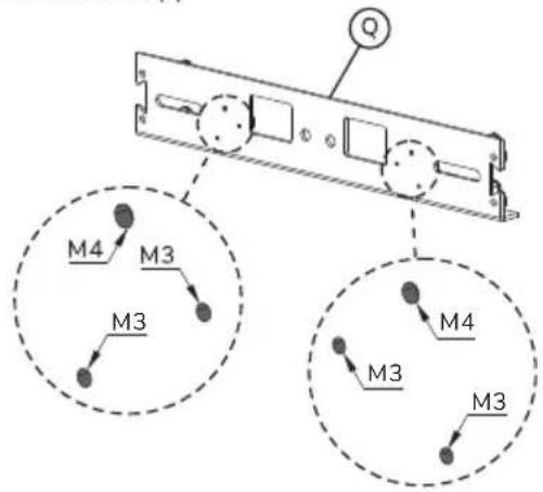
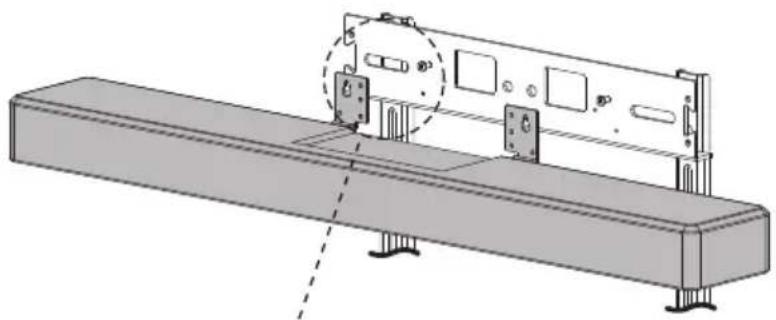


STEP 57 Above screen
EN Attach the speakerbar to the bracket and secure it
NL Bevestig de speakerbar aan de beugel en zet deze vast
DE Befestigen Sie die Soundbar an der Halterung und sichern Sie sie
FR Fixer la barre de son au support et la sécuriser
IT Fissare la soundbar alla staffa e fissarla
ES Coloca la barra de sonido en el soporte y fijala
PT Fixar a barra de som no suporte e fixá-la
PL Przymocuj soundbar do uchwytu i zabezpiecz ją
biamp Parlé SBC 2


STEP 58 Above screen
EN Attach the videobar to the bracket and secure it
NL Bevestig de videobar aan de beugel en zet deze vast
DE Befestigen Sie die Videobar an der Halterung und sichern Sie sie
FR Fixer le vidéobar au support et le sécuriser
IT Fissare la videobar alla staffa e fissarla
ES Coloca el videobar en el soporte y fijalo
PT Fixar a barra de vídeo no suporte e fixá-la
PL Przymocuj wideobar do uchwytu i zabezpiecz go
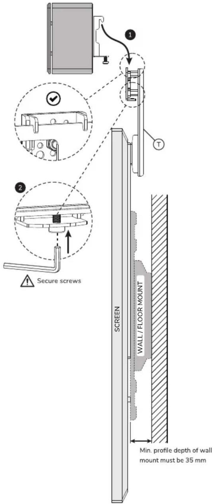
STEP 59 Above screen
EN Attach the videobar to the bracket and secure it
NL Bevestig de videobar aan de beugel en zet deze vast
DE Befestigen Sie die Videobar an der Halterung und sichern Sie sie
FR Fixer le vidéobar au support et le sécuriser
IT Fissare la videobar alla staffa e fissarla
ES Coloca el videobar en el soporte y fijalo
PT Fixar a barra de vídeo no suporte e fixá-la
PL Przymocuj wideobar do uchwytu i zabezpiecz go
Lenovo ThinkSmart One
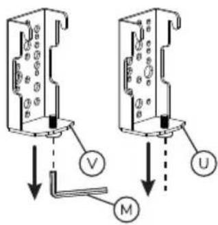

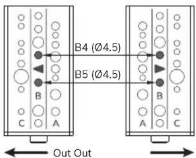


STEP 60 Above screen
EN Attach the videobar to the bracket and secure it
NL Bevestig de videobar aan de beugel en zet deze vast
DE Befestigen Sie die Videobar an der Halterung und sichern Sie sie
FR Fixer le vidéobar au support et le sécuriser
IT Fissare la videobar alla staffa e fissarla
ES Coloca el videobar en el soporte y fijalo
PT Fixar a barra de vídeo no suporte e fixá-la
PL Przymocuj wideobar do uchwytu i zabezpiecz go

STEP 61 Above screen
EN Adjust the height of the videobar to the desired position
NL Stel de hoogte van de videobar in op de gewenste positie
DE Stellen Sie die Höhe der Videobar auf die gewünschte Position ein
FR Ajuster la hauteur de la barre vidéo à la position souhaitée
IT Regolare l'altezza della videobar nella posizione desiderata
ES Ajuste la altura de la videobarra a la posición deseada
PT Ajustar a altura da barra de vídeo para a posição pretendida
PL Dostosuj wysokość paska wideo do żądanej pozycji


EN ! CAUTION
- To ensure safety, please read this manual carefully before installation and follow the instructions. Store this manual in a secure place for future reference.
- The manufacturer shall not be legally responsible for any equipment damage or personal injury caused by incorrect installation or operation other than that covered in this manual.
- The mount is designed for easy installation and removal. The manufacturer shall not be liable for damage to equipment or personal injuries arising out of human factors or acts of nature, such as earthquake or typhoon.
- It is recommended that the mount be installed by qualified personnel only.
- At least two persons are needed to install or remove the product to avoid hazard of falling objects.
- Please carefully inspect the area where the mount is to be installed:
- Avoid places that are subject to high temperatures, humidity or contact with water.
- Do not install the product near air conditioning vents or areas with excess dust and fumes.
- Only install on vertical walls and avoid slanted surfaces.
- Do not install in places subject to any shock or vibration.
- Do not install in places subject to direct exposure to bright light, as it may cause eye fatigue when viewing the display panel.
- Maintain sufficient space around the display to ensure adequate ventilation.
- To ensure safe installation, first check the structure of the wall, ceiling or floor and select a secure mounting location.
- The wall, ceiling or floor should be strong enough to sustain a weight of at least four times of the display and mount combined. The mounting location must be able to withstand earthquake or other strong shock.
- Do not modify any accessories or use broken parts. Contact your dealer with any questions.
- Tighten all screws (do not exert excessive force to avoid breaking the screw or damaging its thread).
- Drill holes and bolts will be left in the wall, ceiling or floor once the display and bracket are removed. Stains may occur after extended use.
- Since the manufacturer has no way to control the wall, ceiling or floor type and installation of the mount, the warranty of the product shall only cover the body of the mount. The warranty period of the product is 5 years.
- Please consult the English language manual for any dispute on conditions.
DE ! VORSICHT


- STEP 1
- STEP 2 BELOW SCREEN
- STEP 4 BELOW SCREEN
- STEP 5 BELOW SCREEN
- STEP 6 BELOW SCREEN
- STEP 7 BELOW SCREEN
- OPTION BELOW SCREEN
- STEP 8 BELOW SCREEN
- STEP 10 BELOW SCREEN
- SELECT VIDEOBAR MODEL
- PARTS TO USE
- INSTRUCTION STEP
- STEP 11-13
- STEP 14-16
- STEP 17-19
- STEP 11 BELOW SCREEN
- STEP 12 BELOW SCREEN
- STEP 13 BELOW SCREEN
- STEP 14 BELOW SCREEN
- STEP 15 BELOW SCREEN
- STEP 16 BELOW SCREEN
- STEP 17 BELOW SCREEN
- STEP 18 A BELOW SCREEN
- STEP 18 B BELOW SCREEN
- STEP 19 BELOW SCREEN
- STEP 20 BELOW SCREEN
- STEP 21 BELOW SCREEN
- STEP 22 BELOW SCREEN
- STEP 23 BELOW SCREEN
- STEP 24 BELOW SCREEN
- STEP 25 BELOW SCREEN
- STEP 26 BELOW SCREEN
- STEP 27 BELOW SCREEN
- STEP 28 BELOW SCREEN
- STEP 29 BELOW SCREEN
- STEP 30 BELOW SCREEN
- STEP 31 BELOW SCREEN
- STEP 32 ABOVE SCREEN
- STEP 33 ABOVE SCREEN
- STEP 34 ABOVE SCREEN
- STEP 35 ABOVE SCREEN
- STEP 36 ABOVE SCREEN
- STEP 37 ABOVE SCREEN
- OPTION ABOVE SCREEN
- STEP 38 ABOVE SCREEN
- STEP 39 ABOVE SCREEN
- STEP 40 ABOVE SCREEN
- STEP 41-43
- STEP 44-46
- STEP 47-49
- STEP 41 ABOVE SCREEN
- STEP 42 ABOVE SCREEN
- STEP 43 ABOVE SCREEN
- STEP 44 ABOVE SCREEN
- STEP 45 ABOVE SCREEN
- STEP 46 ABOVE SCREEN
- STEP 47 ABOVE SCREEN
- STEP 48 A ABOVE SCREEN
- STEP 48 B ABOVE SCREEN
- STEP 49 ABOVE SCREEN
- STEP 50 ABOVE SCREEN
- STEP 51 ABOVE SCREEN
- STEP 52 ABOVE SCREEN
- STEP 53 ABOVE SCREEN
- STEP 54 ABOVE SCREEN
- STEP 55 ABOVE SCREEN
- STEP 56 ABOVE SCREEN
- STEP 57 ABOVE SCREEN
- STEP 58 ABOVE SCREEN
- STEP 59 ABOVE SCREEN
- STEP 60 ABOVE SCREEN
- STEP 61 ABOVE SCREEN
- EN ! CAUTION
- DE ! VORSICHT
Brand : NeoMounts
Model : AV30-500BL
Category : Uncategorized