
HM81MK - Saw McKenzie - Free user manual and instructions
Find the device manual for free HM81MK McKenzie in PDF.


| Brand | McKenzie |
| Model | HM81MK |
| Product type | Pendulum circular saw (mitre saw) |
| Weight | 7 kg |
| Power supply | 220-240 V~, 50 Hz |
| Rated power (S1) | 1400 W |
| Maximum power (S6 25%) | 1700 W |
| No-load speed | 4900 min⁻¹ |
| Saw blade (diameter, bore, thickness) | ø 210 x ø 30 x 2.6 mm |
| Number of teeth | 40 |
| Max. tooth width | 3 mm |
| Pivot range (mitre) | -45° / 0° / +45° (left) |
| Rotary table | 0° to 45° to the left |
| Cutting width at 90° | 115 x 60 mm |
| Cutting width at 45° | 115 x 25 mm |
| Cutting width at double mitre (2x45°) | 80 x 25 mm |
| Cutting depth | Continuously adjustable via limiting screw |
| Laser guide | Class 2, wavelength 650 nm, <1 mW |
| Protection class | II (double insulation) |
| Sound pressure level | 96.5 dB(A) (uncertainty K=3 dB) |
| Sound power level | 109.5 dB(A) (uncertainty K=3 dB) |
| Main functions | Mitre cut, circular cut, double mitre, depth adjustment, guide laser |
| Maintenance and cleaning | Clean chips, oil rotating parts, check carbon brushes |
| Safety | Mobile blade guard, shaft lock, emergency stop via switch, protective cover |
| Wear parts | Carbon brushes, saw blade, table inserts, dust bag, V-belts |
| Included accessories | Clamping device, anti-tilt protection, chip collection bag, hex key |
| Manufacturer | SAS Equipement de la Maison, 24 rue Auguste Chabrières, 75015 Paris, France |
Frequently Asked Questions - HM81MK McKenzie
User questions about HM81MK McKenzie
0 question about this device. Answer the ones you know or ask your own.
Ask a new question about this device
Download the instructions for your Saw in PDF format for free! Find your manual HM81MK - McKenzie and take your electronic device back in hand. On this page are published all the documents necessary for the use of your device. HM81MK by McKenzie.
USER MANUAL HM81MK McKenzie
natural_image
Exterior view of a MCKENZIE cutting machine tool with a caliper and scale (no text or symbols on the device itself)HM81MK
| DE | Kapp- und GehrungssägeOriginalbedienungsanleitung | 5 |
| GB | Cross-cut mitre sawTranslation of original instruction manual | 21 |
| FR | Scie à onglet pendulaireTraduction des instructions d'origine | 35 |
| PT | Serra de esquadria e angularTradução do manual de operação original | 51 |
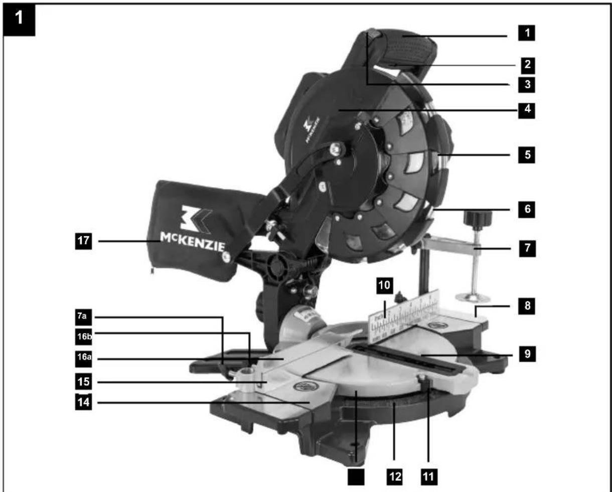
text_image
1 2 3 4 5 6 7 8 9 10 11 12 14 15 16a 16b 7a MCKENZIE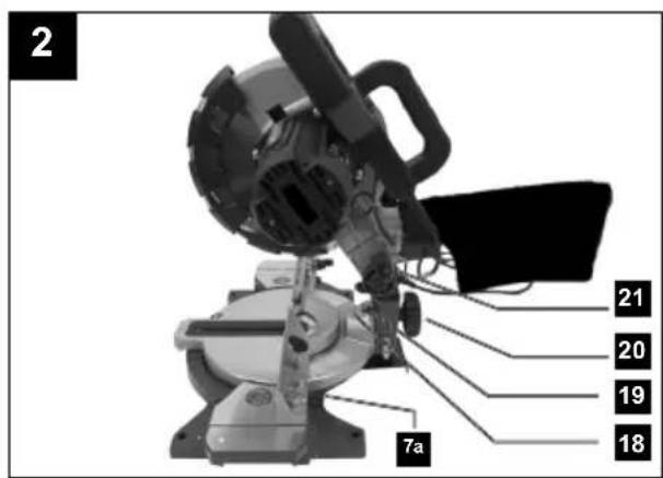
text_image
2 7a 21 20 19 18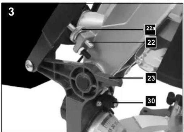
text_image
3 22a 22 23 30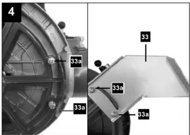
text_image
4 33a 33a 33a 33a 33a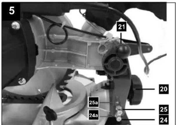
text_image
5 21 20 25a 24a 25 24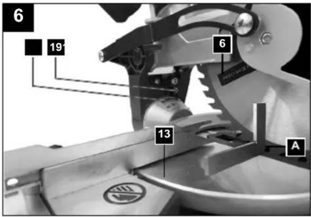
text_image
6 19 6 13 A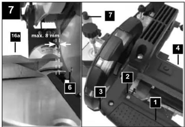
text_image
7 16a max. 8 mm 6 7 4 2 3 1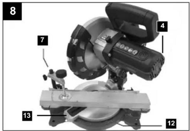
text_image
8 4 7 13 12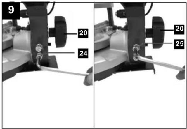
text_image
9 20 24 20 25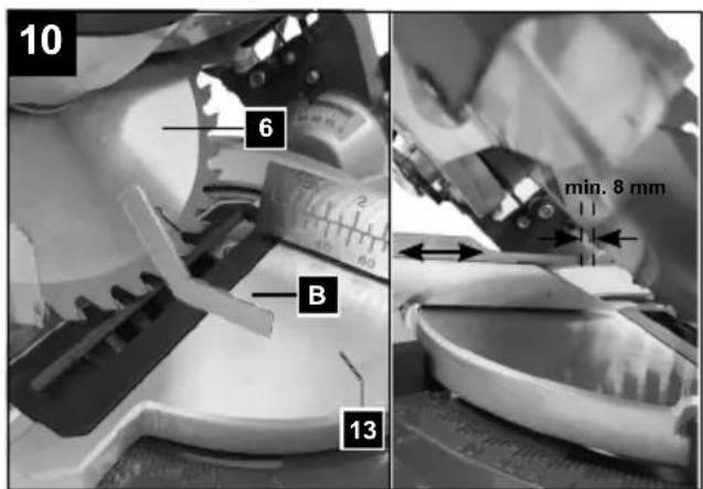
text_image
10 6 B min. 8 mm 13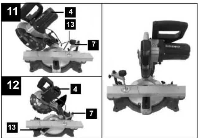
text_image
11 4 13 7 12 4 7 13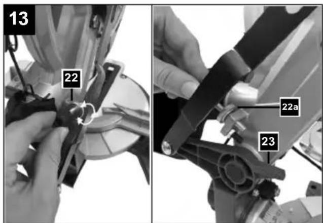
text_image
13 22 22a 23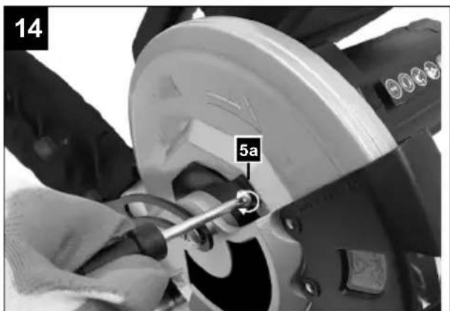
text_image
14 5a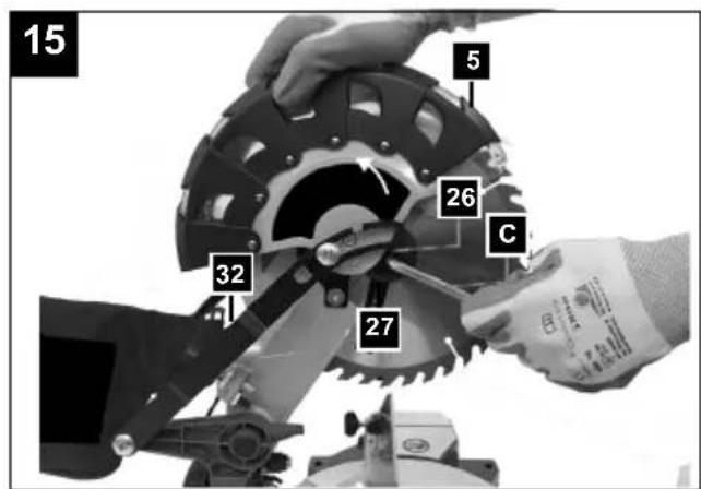
text_image
15 5 26 32 27 C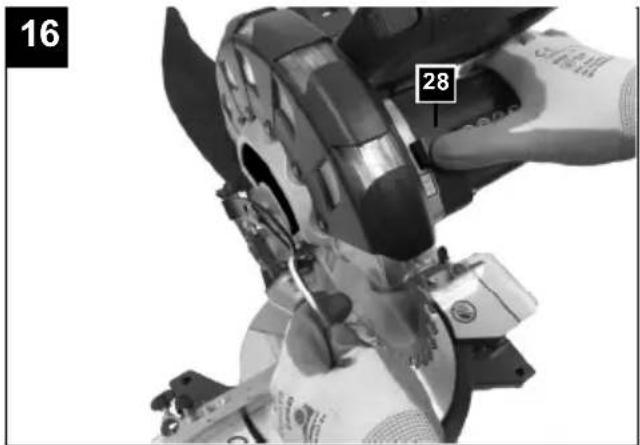
natural_image
Close-up of hands operating a mechanical device with a numbered label (16 and 28) on the left side, no readable text or symbols beyond the number.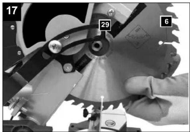
text_image
17 29 6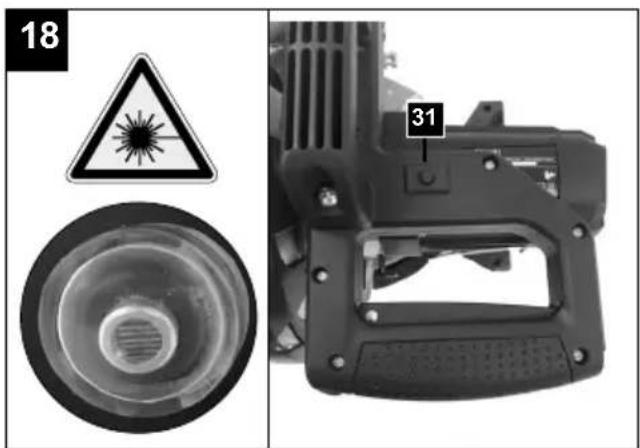
text_image
18 31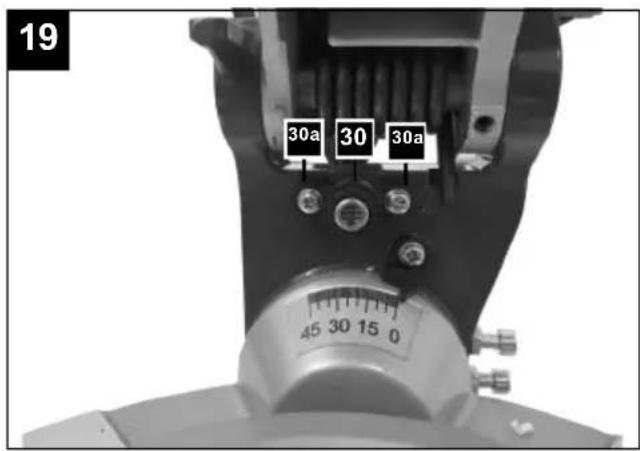
text_image
19 30a 30 30a 45 30 15 0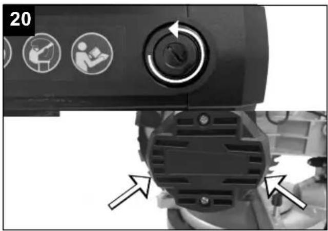
text_image
20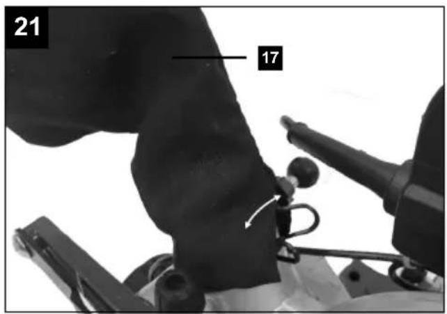
text_image
21 17Explanation of the symbols on the device
Symbols are used in this manual to draw your attention to potential hazards. The safety symbols and the accompanying explanations must be fully understood. The warnings themselves will not rectify a hazard and cannot replace proper accident prevention measures.
 | Warning - read the instruction manual to reduce the risk of injury. |
 | Wear hearing protection. Excessive noise can result in a loss of hearing. |
 | Wear a dust protection mask. When machining wood and other materials, harmful dust may be generated. Do not machine material containing asbestos! |
 | Wear eye protection. Sparks created during work or fragments, chippings and dust ejected by the device can case sight loss. |
 | Important! Risk of injury. Never reach into the running saw blade! |
 | Attention! Laser radiation |
 | Protection class II (double insulation) |
 | The product complies with the applicable European directives. |
| ⚠ Attention! | We have marked points in these operating instructions that impact your safety with this symbol. |
Table of contents: Page:
- Introduction....23
- Device description (Fig. 1-21).... 23
- Scope of delivery 24
- Proper use 24
- Safety information....24
- Technical data.... 28
- Before commissioning 29
- Attachment and operation....29
- Transport....32
- Maintenance 32
- Storage 32
- Electrical connection 33
- Disposal and recycling.... 33
- Troubleshooting 34
- Declaration of conformity 68
1. Introduction
Manufacturer:
We hope your new tool brings you much enjoyment and success.
Note:
In accordance with the applicable product liability laws, the manufacturer of this device assumes no liability for damage to the device or caused by the device arising from:
- Improper handling,
- Failure to comply with the operating instructions.
• Repairs carried out by third parties, unauthorised specialists. - Installing and replacing non-original spare parts,
• Application other than specified, - Failure of the electrical system in the event of the electrical regulations and VDE provisions 0100, DIN 13 / VDE0113 not being observed.
Please consider:
Read through the complete text in the operating manual before installing and commissioning the device.
The operating manual is intended to help the user to become familiar with the machine and take advantage of its application possibilities in accordance with the recommendations.
The operating manual includes important instructions for safe, proper and economic operation of the device, for avoiding danger, for minimising repair costs and downtimes, and for increasing the reliability and extending the service life of the device.
In addition to the safety instructions in this operating manual, you must also observe the regulations applicable to the operation of the device in your country.
Keep the operating manual package with the machine at all times and store it in a plastic cover to protect it from dirt and moisture. They must be read and carefully observed by all operating personnel before starting the work.
The device may only be used by personnel who have been trained to use it and who have been instructed with respect to the associated hazards. The required minimum age must be observed.
In addition to the safety instructions in this operating manual and the separate regulations of your country, the generally recognised technical rules relating to the operation of such machines must also be observed.
We accept no liability for accidents or damage that occur due to a failure to observe this manual and the safety instructions.
2. Device description (Fig. 1-21)
- Handle
- On/off switch
- Locking switch
- Machine head
- Moving saw blade guard
- Saw blade
- Clamping device
- Workpiece support
- Table inlay
- Set screw for rotary table
- Pointer
- Scale
- Rotary table
- fixed saw table
- Stop rail
16a. Moveable stop rail
16b. Locking screw - Dust bag
- Scale
- Pointer
- Locking screw
- Locking pin
- Screw for cutting depth limiting
- Stop for cutting depth limiting
- Adjusting screw (90°)
- Adjusting screw (45°)
- Flange screw
- Outer flange
- Sawing shaft lock
- Inner flange
- Laser
- Laser ON/OFF switch
- Guide bar
- Tilt protection
A.) 90° stop bracket (not included in the scope of supply)
B.) 45^ stop bracket (not included in the scope of delivery)
C.) Allen key, 6 mm
3. Scope of delivery
- Chop saw
- Clamping device (7)
- Tilt protection (33)
- Dust bag (17)
- Allen key, 6 mm (C)
- Operating manual
4. Proper use
The chop saw is used for the cutting of wood and plastic, according to the machine size. The saw is not suitable for the cutting of firewood.
Warning! Do not use the device to cut materials other than those described in the operating manual.
Warning! The supplied saw blade is only intended for the sawing of wood! Do not use this blade for sawing firewood!
The machine may only be used in the intended manner. Any use beyond this is improper. The user/operator, not the manufacturer, is responsible for damages or injuries of any type resulting from this.
Only suitable saw blades may be used for the machine. The use of any type of cutting wheels is prohibited.
An element of the intended use is also the observance of the safety instructions, as well as the assembly instructions and operating information in the operating manual.
Persons who operate and maintain the machine must be familiar with it and must be informed about potential dangers.
In addition, the applicable accident prevention regulations must be strictly observed.
Other general occupational health and safety-related rules and regulations must be observed.
The liability of the manufacturer and resulting damages are excluded in the event of modifications of the machine.
Despite use as intended, specific risk factors cannot be entirely eliminated. Due to the design and layout of the machine, the following risks remain:
- Contact with the saw blade in the exposed sawing area.
- Reaching into the running saw blade (cutting injury).
- Kick-back of workpieces and workpiece parts.
- Saw blade breakage.
- Ejection of faulty carbide parts of the saw blade.
- Hearing damage when the necessary hearing protection is not used.
- Harmful emissions of wood dusts during use in enclosed areas.
Please observe that our equipment was not designed with the intention of use for commercial or industrial purposes. We assume no guarantee if the equipment is used in commercial or industrial applications, or for equivalent work.
5. Safety information
General power tool safety warnings
⚠ WARNING! Read all safety warnings, instructions, illustrations and specifications provided with this power tool. Failure to observe safety information and instructions can result in electric shock, fire and/or serious injuries.
Save all warnings and instructions for future reference.
The term “electric tool” used in the safety instructions refers to mains-powered electrical tools (with a mains cable) and battery-powered electrical tools (without a mains cable).
Work area safety
a) Keep work area clean and well lit.
Cluttered or dark areas invite accidents.
b) Do not operate power tools in explosive atmospheres, such as in the presence of flammable liquids, gases or dust.
Power tools create sparks which may ignite the dust or fumes.
c) Keep children and bystanders away while operating a power tool.
Distractions can cause you to lose control.
Electrical safety
a) Power tool plugs must match the outlet. Never modify the plug in any way. Do not use any adapter plugs with earthed (grounded) power tools. Unmodified plugs and matching outlets will reduce risk of electric shock.
b) Avoid body contact with earthed or grounded surfaces, such as pipes, radiators, ranges and refrigerators. There is an increased risk of electric shock if your body is earthed or grounded.
c) Do not expose power tools to rain or wet conditions.
Water entering a power tool will increase the risk of electric shock.
d) Do not use the cable for another purpose, for example, carrying or hanging the power tool or pulling the plug out of the socket.
Keep the cable away from heat, oil, sharp edges or moving device parts. Damaged or coiled cables increase the risk of an electric shock.
e) If you work with a power tool outdoors, only use extension cables that are also suitable for outdoor use.
Using an extension cable suitable for outdoor use reduces the risk of an electric shock.
f) If you cannot avoid using the electrical tool in a wet environment, use a fault-current circuit breaker.
Use of an RCD reduces the risk of electric shock.
Personal safety
a) Stay alert, watch what you are doing and use common sense when operating a power tool. Do not use a power tool while you are tired or under the influence of drugs, alcohol or medication.
A moment of carelessness when using electrical tools can result in serious injuries.
b) Use personal protective equipment. Always wear eye protection.
Protective equipment such as a dust mask, non-skid safety shoes, hard hat or hearing protection used for appropriate conditions will reduce personal injuries.
c) Prevent unintentional starting. Ensure the switch is in the off-position before connecting to power source and/or battery pack, picking up or carrying the tool. Carrying power tools with your finger on the switch or energising power tools that have the switch on invites accidents.
d) Remove any adjusting key or wrench before turning the power tool on.
A tool or spanner that is located in a rotating device part may result in injuries.
e) Do not overreach.
Keep proper footing and balance at all times.
This enables better control of the power tool in unexpected situations.
f) Dress properly. Do not wear loose clothing or jewellery. Keep hair, clothing and gloves away from moving parts. Loose clothes, jewellery or long hair can be caught in moving parts.
g) If dust extraction and collection devices can be mounted, make sure that they are connected and used properly.
Use of dust collection can reduce dust-related hazards.
h) Do not let familiarity gained from frequent use of tools allow you to become complacent and ignore tool safety principles. A careless action can cause severe injury within a fraction of a second.
Power tool use and care
a) Do not overload the device.
Use the correct power tool for your application. The correct power tool will do the job better and safer at the rate for which it was designed.
b) Do not use the power tool if the switch does not turn it on and off. Any power tool that cannot be controlled with the switch is dangerous and must be repaired.
c) Disconnect the plug from the power source and/or remove the battery pack, if detachable, from the power tool before making any adjustments, changing accessories, or storing power tools.
Such preventive safety measures reduce the risk of starting the power tool accidentally.
d) Store idle power tools out of the reach of children and
do not allow persons unfamiliar with the power tool or these instructions to operate the power tool. Power tools are dangerous in the hands of untrained users.
e) Maintain power tools and accessories.
Check whether moving parts function properly and do not get stuck and whether parts are broken or are damaged and thus adversely affect the electric tool function. If damaged, have the power tool repaired before use. Many accidents are caused by poorly maintained power tools.
f) Keep cutting tools sharp and clean. Properly maintained cutting tools with sharp cutting edges are less likely to bind and are easier to control.
g) Use the power tool, accessories and tool bits etc. in accordance with these instructions, taking into account the working conditions and the work to be performed. Use of the power tool for operations different from those intended could result in a hazardous situation.
h) Keep handles and grasping surfaces dry, clean and free from oil and grease. Slippery handles and grasping surfaces do not allow for safe handling and control of the tool in unexpected situations.
Service
a) Have your power tool serviced by a qualified repair person using only identical replacement parts. This will ensure that the safety of the power tool is maintained.
Warning! This power tool generates an electromagnetic field during operation. This field can impair active or passive medical implants under certain conditions. In order to prevent the risk of serious or deadly injuries, we recommend that persons with medical implants consult with their physician and the manufacturer of the medical implant prior to operating the power tool.
Safety instructions for chop and mitre saws
a) Mitre saws are intended to cut wood or wood-like products, they cannot be used with abrasive cut-off wheels for cutting ferrous material such as bars, rods, studs, etc. Abrasive dust causes moving parts such as the lower guard to jam. Sparks from abrasive cutting will burn the lower guard, the kerf insert and other plastic parts.
b) Use clamps to support the workpiece whenever possible. If supporting the workpiece by hand, you must always keep your hand at least 100 mm from either side of the saw blade. Do not use this saw to cut pieces that are too small to be securely clamped or held by hand. If your hand is placed too close to the saw blade, there is an increased risk of injury from blade contact.
c) The workpiece must be stationary and clamped or held against both the fence and the table. Do not feed the workpiece into the blade or cut "freehand" in any way. Unrestrained or moving workpieces could be thrown at high speeds, causing injury.
d) Push the saw through the workpiece. Do not pull the saw through the workpiece. To make a cut, raise the saw head and pull it out over the workpiece without cutting. Start the motor, press the saw head down and push the saw through the workpiece. Cutting on the pull stroke is likely to cause the saw blade to climb on top of the workpiece and violently throw the blade assembly towards the operator.
e) Never cross your hand over the intended line of cutting either in front or behind the saw blade. Supporting the workpiece "cross handed" i.e. holding the workpiece to the right of the saw blade with your left hand or vice versa is very dangerous.
f) Do not reach behind the fence while the blade is spinning. Observe the 100 mm safety distance between hands and the rotating saw blade (this applies to both sides of the saw blade, e.g. also when removing waste pieces of wood). The proximity of the spinning saw blade to your hand may not be obvious and you may be seriously injured.
g) Inspect your workpiece before cutting. If the workpiece is bowed or warped, clamp it with the outside bowed face toward the fence. Always make certain that there is no gap between the workpiece, fence and table along the line of the cut. Bent or warped workpieces can twist or shift and may cause binding on the spinning saw blade while cutting. There should be no nails or foreign objects in the workpiece.
h) Do not use the saw until the table is clear of all tools, wood scraps, etc., except for the workpiece. Small debris or loose pieces of wood or other objects that contact the revolving blade can be thrown with high speed.
i) Only cut one workpiece at a time. Stacked multiple workpieces cannot be adequately clamped or braced and may bind on the blade or shift during cutting.
j) Ensure the mitre saw is mounted or placed on a level, firm work surface before use. A level and firm work surface reduces the risk of the mitre saw becoming unstable.
k) Plan your work. Every time you change the bevel or mitre angle setting, make sure the adjustable fence is set correctly to support the workpiece and will not interfere with the blade or the guarding system.
Without turning the tool "ON" and with no workpiece on the table, move the saw blade through a complete simulated cut to assure there will be no interference or danger of cutting the fence.
I) Provide adequate support such as table extensions, saw horses, etc. for a workpiece that is wider or longer than the table top. Workpieces that are longer or wider than the table of the chop and mitre saw can tip if they are not properly supported. If the cut-off piece or workpiece tips, it can lift the lower guard or be thrown by the spinning blade.
m) Do not use another person as a substitute for a table extension or as additional support. Unstable support of the workpiece can lead to the blade becoming jammed. Also, the workpiece could shift during the cutting process, pulling you or your assistant into the rotating blade.
n) The cut-off piece must not be jammed or pressed by any means against the spinning saw blade. If confined, i.e. using length stops, the cut-off piece could get wedged against the blade and thrown violently.
o) Always use a clamp or a fixture designed to properly support round material such as rods or tubing. Rods have a tendency to roll while being cut, causing the blade to "bite" and pull the work with your hand into the blade.
p) Let the blade reach full speed before contacting the workpiece. This will reduce the risk of the workpiece being thrown.
q) If the workpiece or blade becomes jammed, turn the mitre saw off. Wait for all moving parts to stop and disconnect the plug from the power source and/or remove the battery pack. Then, remove the jammed material. If you continue sawing with such jamming this can result in a loss of control or to the chop and mitre saw being damaged.
r) After finishing the cut, release the switch, hold the saw head down and wait for the blade to stop before removing the cut-off piece. Reaching with your hand near the coasting blade is dangerous.
s) Hold the handle firmly when making an incomplete cut or when releasing the switch before the saw head is completely in the down position. The braking action of the saw may cause the saw head to be suddenly pulled downward, causing a risk of injury.
Safety instructions for the handling of saw blades
1 Do not use damaged or deformed saw blades.
2 Do not use saw blades with cracks. Separate cracked saw blades. Repairs are not permitted.
3 Do not use saw blades made of high speed steel.
4 Check the condition of the saw blades before using the chop and slide saw.
5 Make sure that a suitable saw blade for the material to be cut is selected.
6 Only use saw blades recommended by the manufacturer.
Saw blades designed to cut wood and similar materials must comply with EN 847-1.
7 Do not use saw blades made of high-speed alloy steel (HSS steel).
8 Only use saw blades for which the maximum permissible speed is not lower than the maximum spindle speed of the chop and slide saw, and which are suitable for the material to be cut.
9 Observe the rotational direction of the saw blade.
10 Only use saw blades if you have mastered their use.
11 Observe the maximum speed. The maximum speed specified on the saw blade may not be exceeded. If specified, observe the speed range.
12 Clean dirt, grease, oil and water off of the clamping surfaces.
13 Do not use any loose reducing rings or bushes for the reducing of holes on saw blades.
14 Make sure that fixed reducer rings for securing the saw blade have the same diameter and have at least 1/3 of the cutting diameter.
15 Make sure that fixed reducer rings are parallel to each other.
16 Handle saw blade with caution. They are ideally stored in the originally package or special containers. Wear protective gloves in order to improve grip and to further reduce the risk of injury.
17 Prior to the use of saw blades, make sure that all protective devices are properly fastened.
18 Prior to use, ensure that the saw blade meets the technical requirements of this chop and pull saw, and is properly fastened.
19 Only use the supplied saw blade for cutting wood, never for the processing of metals.
20 Use only a saw blade with a diameter that matches the specifications on the saw.
21 Use additional workpiece supports if this is necessary for the stability of the workpiece.
22 Workpiece support extensions must always be secured and used during work.
23 Replace table inserts when worn!
24 Avoid overheating the saw teeth.
25 When sawing plastic, avoid melting of the plastic. Use the appropriate saw blades for this purpose. Replace damaged or worn saw blades immediately. When the saw blade overheats, stop the machine. Allow the saw blade to cool down before using the machine again.
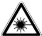
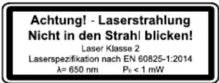
Attention: Laser beam
Do not stare into beam
Laser class 2
Protect yourself and your environment from accidents using suitable precautionary measures!
- Do not look directly into the laser beam with unprotected eyes.
- Never look into the path of the beam.
- Never point the laser beam towards reflecting surfaces and persons or animals. Even a laser beam with a low output can cause damage to the eyes.
- Caution - methods other than those specified here can result in dangerous radiation exposure.
- Never open the laser module. Unexpected exposure to the beam can occur.
- The laser may not be replaced with a different type of laser.
- Repairs of the laser may only be carried out by the laser manufacturer or an authorised representative.
Residual risks
The electric tool has been built according to state-of-the-art and the recognised technical safety rules. However, individual residual risks can arise during operation.
- Health hazard due to electrical power, with the use of improper electrical connection cables.
• Furthermore, despite all precautions having been met, some non-obvious residual risks may still remain. -
Residual risks can be minimised if the "Important information" and the "Proper use" are observed along with the whole of the operating instructions.
-
Do not load the machine unnecessarily: excessive pressure when sawing will quickly damage the saw blade, which results in reduced output of the machine in the processing and in cut precision.
- When cutting plastic material, please always use clamps: the parts which should be cut must always be fixed between the clamps.
- Avoid accidental starting of the machine: the start button may not be pressed when inserting the plug in an outlet.
- Use the tool that is recommended in this manual. This is how to ensure that your machine provides optimum performance.
- Keep your hands away from the work area, when the machine is in operation.
- Before performing setting or maintenance work, release the start button and pull out the power plug.
6. Technical data
AC motor 220 - 240 V\~ 50Hz
| Nominal power S1 1400 Watts | |
| Operating mode S6 25%* 1700 W | |
| Idle speed n_0 | 4900 min ^-1 |
| Carbide saw blade ø 210 x ø 30 x 2.6 mm | |
| Number of teeth 40 | |
| Maximum tooth width of the saw blade | 3 mm |
| Pivot range -45° / 0° / +45° | |
| Mitre cut 0° to 45° to the left | |
| Saw width at 90° 115 x 60 mm | |
| Saw width at 45° 115 x 25 mm | |
| Saw width at 2 x 45° (double mitre cut) | 80 x 25 mm |
| Protection class | II / ☑ |
| Laser class | 2 |
| Laser wavelength | 650 nm |
| Power of laser | < 1 mW |
| Weight | 7 kg |
* Operating mode S6, uninterrupted, periodic operation. The mode comprises of a start-up period, a time with constant load and an idle time. The operating time is 10 mins, the relative duty cycle is 25% of the operating time.
The workpiece must have a minimum height of 3 mm and a minimum width of 10 mm. Make sure that the workpiece is always secured with the clamping device.
Noise
The noise values have been determined in accordance with EN 62841.
Sound pressure level L_pA : 96.5 dB
Uncertainty K_pA : 3 dB
Sound power level L_WA : 109.5 dB
Uncertainty K_WA : 3 dB
Wear hearing protection.
Excessive noise can result in a loss of hearing.
The specified noise emission values have been measured in accordance with a standardised test procedure and can be used to compare one power tool with another.
The specified noise emission values can also be used for an initial estimation of the exposure.
Warning:
- The noise emission values can vary from the specified values during the actual use of the power tool, depending on the type and the manner in which the power tool is used, and in particular the type of workpiece being processed..
- Try to keep the stress as low as possible. For example: Limit working time. In the process all parts of the operating cycle must be taken into account (such as times in which the electric tool is switched off or time in which it is switched on, but is not running under a load).
7. Before commissioning
- Open the packaging and carefully remove the device.
- Remove the packaging material, as well as the packaging and transport safety devices (if present).
- Check whether the scope of delivery is complete.
- Check the device and accessory parts for transport damage.
- If possible, keep the packaging until the expiry of the warranty period.
ATTENTION
The device and the packaging are not children's toys! Do not let children play with plastic bags, films or small parts! There is a danger of choking or suffocating!
- The machine must be securely installed. Secure the machine through the holes on the fixed saw table (14) with 4 screws (not included in the scope of delivery) to a workbench, machine stand or similar.
• Fit the tilt protection (33). - Prior to commissioning, all covers and safety devices must be mounted correctly.
- It must be possible for the saw blade to run freely.
- In case of previously machined wood, be aware of any foreign objects, such as nails or screws, etc.
- Before pressing the on/off switch, make sure that the saw blade is correctly fitted, and that moving parts run smoothly.
- Before connecting the machine, make certain that the data on the type plate matches with the mains power data.
7.1 Checking the movable saw blade guard safety device (5)
The saw blade guard protects against accidental contact with the saw blade and against flying chips.
Check function.
To do this, fold the saw down:
- The saw blade guard must expose the saw blade when it is swung down without touching other parts.
- When the saw is folded up to the initial position, the saw blade guard must automatically cover the saw blade.
8. Attachment and operation
⚠ Attention!
Always make sure the product is fully assembled before commissioning!
8.1 Setting up the chop saw (Fig. 1/2/4/5)
- To adjust the rotary table (13), loosen the locking screw (10) by approx. 2 turns.
- Rotate the rotary table (13) and pointer (11) to the desired angle on the scale (12) and lock in place with the locking screw (10).
-
The saw is unlocked from the lower position by gently pressing down on the machine head (4) and, at the same time, pulling out the locking pin (21) from the engine mount.
-
Swivel the machine head (4) upwards.
- Loosen the Phillips screws (33a) on the underside of the saw. Fasten the tilt protection (33) and retighten the Phillips screws (33a).
- The clamping devices (7) can be attached to both sides of the fixed saw table (14). Insert the clamping devices (7) into the holes provided for them on the rear side of the stop rail (15) and secure them with the star grip screws (7a).
For mitre cuts 0^-45^ , mount the clamping device (7) on one side (right) only (see Fig. 11-12). - The machine head (4) can be tilted to the left to max. 45^ by loosening the locking screw (20).
8.2 Fine adjustment of the stop for 90° chop cut (Fig. 1/2/5/6)
Stop bracket not included in the scope of delivery.
- Lower the machine head (4) and fix it with the locking pin (21).
- Loosen the locking screw (20).
- Place the stop bracket (A) between the saw blade (6) and the rotary table (13).
- Loosen the locknut (24a).
- Adjust the adjustment screw (24) until the angle between the saw blade (6) and the rotary table (13) is 90^ .
• Re-tighten the locknut (24a). - Then check the position of the angle display. If necessary, loosen the pointer (19) with a Phillips screw-driver, set the scale (18) to 0^ position and re-tighten the retaining screw.
8.3 90° chop cut and rotary table 0° (Fig. 1/2/7)
Attention! For 90° chop cuts, the moveable stop rails (16a) must be fixed in the inner position.
- Loosen the locking screws (16b) on the moveable stop rail (16a) and push the moveable stop rail (16a) inwards.
- The moveable stop rail (16a) must be locked in a position far enough from the inner position that the distance between the stop rail (16a) and the saw blade (6) is no more than 8 mm.
- Before making the cut, check that no collision could occur between the stop rail (16a) and the saw blade (6).
- Tighten the locking screws (16b) again.
- Move the machine head (4) to the upper position.
- Place the wood to be cut against the stop rail (16) and on the rotary table (13).
- Secure the material on the fixed saw table (14) with the clamping devices (7) to prevent it from shifting during the cutting process.
- Unlock the locking switch (3) and press the on/off switch (2) to switch the motor on.
- Move the machine head (4) with the handle (1) evenly and with light pressure downwards until the saw blade (6) has cut through the workpiece.
- When the sawing process is finished, return the machine head to the upper resting position and release the ON/OFF switch (2).
- Attention! The return spring automatically raises the machine. Do not let go of the handle (1) after finishing cutting but move the machine head slowly upwards with light counter-pressure.
8.4 90° chop cut and rotary table 0°-45° (Fig. 1/7/8)
Angled cuts of 0^ - 45^ to the left and right can be carried out with the chop saw.
Attention! For 90° chop cuts, the moveable stop rails (16a) must be fixed in the inner position.
- Loosen the locking screw (16b) on the moveable stop rail (16a) and push the moveable stop rail (16a) inwards.
- The moveable stop rail (16a) must be locked in a position far enough from the inner position that the distance between the stop rail (16a) and the saw blade (6) is at least 8 mm.
- Before making the cut, check that no collision could occur between the stop rail (16a) and the saw blade (6).
- Tighten the locking screw (16b) again.
- Loosen the locking screw (10).
- Use the handle (1) to adjust the rotary table to the desired angle.
- The pointer (11) on the rotary table must match the desired angle on the scale (12) on the fixed saw table (14).
- Retighten the locking screw (10) to lock the rotary table (13) in position.
• Make a cut as described in point 8.3.
8.5 Fine adjustment of the stop for 45° mitre cut (Fig. 1/2/5/9/10)
Stop bracket not included in the scope of delivery.
- Lower the machine head (4) and fix it with the locking pin (21).
- Fix the rotary table (13) in the 0^ position. Attention! For mitre cuts (inclined saw head), the moveable stop rail (16a) must be fixed in the outer position.
- Loosen the locking screw (16b) on the moveable stop rail (16a) and push the moveable stop rail (16a) outwards.
- The moveable stop rail (16a) must be locked in a position far enough from the inner position that the distance between the stop rails (16a) and the saw
blade (6) is at least 8 mm.
- Before making the cut, check that no collision could occur between the stop rail (16a) and the saw blade (6).
- Loosen the locking screw (20) and tilt the machine head (4) to the left, to 45^ , using the handle (1).
- Place 45^ stop bracket (b) between saw blade (6) and rotary table (13).
- Loosen the locknut (25a) and the adjustment screw (25) until the angle between the saw blade (6) and the rotary table (13) is exactly 45^ .
• Re-tighten the locknut (25a). - Then check the position of the angle display. If necessary, loosen the pointer (19) with a Phillips screwdriver, set the scale (18) to 45^ position and re-tighten the retaining screw.
8.6 0°-45° mitre cut and rotary table 0° (Fig. 1/2/11)
Mitre cuts of 0^ - 45^ to the working surface can be carried out to the left using the chop saw.
Attention! For mitre cuts (inclined saw head), the moveable stop rail (16a) must be fixed in the outer position.
- Loosen the locking screw (16b) on the moveable stop rail (16a) and push the moveable stop rail (16a) outwards.
- The moveable stop rail (16a) must be locked in a position far enough from the inner position that the distance between the stop rails (16a) and the saw blade (6) is at least 8 mm.
- Before making the cut, check that no collision could occur between the stop rails (16a) and the saw blade (6).
- Tighten the locking screw (16b) again.
- Move the machine head (4) to the upper position.
- Fix the rotary table (13) in the 0^ position.
- Loosen the locking screw (20) and tilt the machine head (4) to the left with the handle (1) until the pointer (19) points to the desired angle on the scale (18).
- Retighten the locking screw (20).
• Make a cut as described in point 8.3.
8.7 0°-45° mitre cut and rotary table 0°-45° (Fig. 2/4/12)
The chop saw can be used for mitre cuts of 0^-45^ to the left of the work surface and of 0^-45^ to the stop rail (double mitre cut).
Attention! For mitre cuts (inclined saw head), the moveable stop rail (16a) must be fixed in the outer position.
- Loosen the locking screw (16b) on the moveable stop rail (16a) and push the moveable stop rail (16a) outwards.
- The moveable stop rail (16a) must be locked in a position far enough from the inner position that the distance between the stop rail (16a) and the saw blade (6) is at least 8 mm.
- Before making the cut, check that no collision could occur between the stop rail (16a) and the saw blade (6).
- Tighten the locking screw (16b) again.
- Move the machine head (4) to the upper position.
- Loosen the rotary table (13) by loosening the locking screw (10).
- Use the handle (10) to adjust the rotary table (13) to the desired angle (see also point 8.4).
- Retighten the locking screw (10) to lock the rotary table in position.
- Loosen the locking screw (20).
- Use the handle (1) to tilt the machine head (4) to the left to the desired angle (see also point 8.6).
- Retighten the locking screw (20).
• Make a cut as described in point 8.3.
8.8 Restricting the cutting depth (Fig. 3/13)
- The cutting depth can be seamlessly adjusted with the screw (22). To do so, loosen the knurled nut on the screw (22a). Set the desired cutting depth by screwing in or unscrewing the screw (22). Then retighten the knurled nut (22a) on the screw (22).
- Check the setting with a test cut.
8.9 Dust bag (Fig. 1/21)
The saw is equipped with a dust bag (17) for chips.
Squeeze together the metal ring on the dust bag and attach it to the outlet opening in the motor area. The dust bag (17) can be emptied via the zip on the underside.
Connection to an external dust extraction system
- Connect the suction hose to the dust extraction.
- The dust extraction system must be suitable for the material to be processed.
- Use a special extraction device to extract dusts that are particularly harmful to health or carcinogenic.
8.10 Replacing the saw blade (Fig. 1/2/14-17)
Pull out the mains plug!
Attention!
Wear protective gloves when changing the saw blade! Risk of injury!
- Swivel the machine head (4) upwards and lock it with the locking pin (21).
- Loosen the fixing screw (5a) of the cover with a Phillips screwdriver.
WARNING! Do not unscrew this screw all the way.
- Fold the saw blade guard (5) up sufficiently that the saw blade guard (5) is above the flange screw (26).
- With one hand, fit the Allen key (C) to the flange screw (26).
- Hold the Allen key (C) and slowly close the saw blade guard (5) until it touches the Allen key (C).
- Firmly press the saw shaft lock (28), and slowly turn the flange screw (26) clockwise. After max. one turn, the saw shaft lock (28) engages.
- Then undo the flange screw (26), by applying a slightly greater force in a clockwise direction.
- Fully unscrew the flange screw (26) and remove the outer flange (27).
- Remove the saw blade (6) from the inner flange (29) and pull it out downwards.
- Carefully clean the flange screw (26), outer flange (27) and inner flange (29).
- Insert the new saw blade (6) in the reverse sequence and tighten.
- Attention! The cutting angle of the teeth, i.e. the direction of rotation of the saw blade (6), must correspond to the direction of the arrow on the housing.
- Before continuing work, check that the safety devices are functioning properly.
- Attention! After each saw blade change, check that the saw blade (6) runs freely in the table cut-out (9) in vertical position as well as when tilted to 45^ .
- Attention! Changing and aligning the saw blade (6) must be carried out properly.
8.11 Laser operation (Fig. 18)
- Switching on: Press the laser ON/OFF switch (31) 1x. A laser line is projected onto the workpiece to be cut, indicating the exact cutting path.
- Switching off: Press the laser ON/OFF switch (31) again.
8.12 Calibrating the laser (Fig. 19)
If the laser (30) is no longer showing the correct cutting line, it can be readjusted. Loosen the Phillips screws (30a) and adjust the laser by sliding it sideways such that the laser beam hits the cutting teeth of the saw blade (6).
9. Transport
- Tighten the locking screw (10) to lock the rotary table (13).
- Push the machine head (4) downwards and lock it with the locking pin (21). The saw is now locked in the lower position.
- Carry the machine on the fixed saw table (14).
- To reassemble the machine, proceed as described in chapter 7.
10. Maintenance
⚠ Warning! Pull out the mains plug before carrying out any adjustments, maintenance or repair work!
General maintenance tasks
Wipe swarf and dust off the machine from time to time with a cloth. Oil the rotating parts once monthly to extend the life of the tool. Do not oil the motor.
Do not use corrosive agents for cleaning the plastic.
Cleaning the movable saw blade guard safety device (5)
Check the saw blade guard for dirt before each start-up.
Remove old shavings and wood splinters using a brush or similar suitable tool.
Brush inspection
If the machine is new, check the carbon brushes after the first 50 operating hours or if a new brush has been mounted. After the initial check, check every 10 operating hours.
If the carbon is worn down to a length of 6 mm, or the spring or the shunt wire is burnt or damaged, both brushes must be replaced. If the brushes are found to be usable after removal, they can be reinstalled.
To service the carbon brushes, open both locks (as shown in figure 20) counter-clockwise. Then remove the carbon brushes.
Re-insert the carbon brushes in reverse order.
Service information
With this product, it is necessary to note that the following parts are subject to natural or usage-related wear, or that the following parts are required as consumables.
Wearing parts*: Carbon brushes, saw blade, table in-lays, dust collection bags, V-belts
* may not be included in the scope of supply!
11. Storage
Store the device and its accessories in a dark, dry and frost-free place that is inaccessible to children. The optimum storage temperature lies between 5 and 30 °C.
Store the power tool in its original packaging.
Cover the electric tool to protect it from dust or moisture.
Store the operating manual with the power tool.
12. Electrical connection
The electrical motor installed is connected and ready for operation. The connection complies with the applicable VDE and DIN provisions. The customer's mains connection as well as the extension cable used must also comply with these regulations.
- The product fulfils the requirements of EN 61000-3-11 and may only be used at the following connection points: This means that use of the product at any freely selectable connection points is not allowed.
- Given unfavourable conditions in the power supply the product can cause the voltage to fluctuate temporarily.
- The product is intended solely for use at connection points that
- a) do not exceed a maximum permissible mains impedance "Z" (Zmax. = 0.382 Ω), or
- b) have a mains constant current carrying capacity of at least 100 A per phase.
- As the user, you are required to ensure, in consultation with your electric power company if necessary, that the connection point at which you wish to operate the product meets one of the two requirements, a) or b), named above.
Important information
In the event of overloading, the motor will switch itself off. After a cool-down period (time varies) the motor can be switched back on again.
Damaged electrical connection cable.
The insulation on electrical connection cables is often damaged.
This may have the following causes:
- Pressure points, where connection cables are passed through windows or doors.
- Kinks where the connection cable has been improperly fastened or routed.
- Places where the connection cables have been cut due to being driven over.
- Insulation damage due to being ripped out of the wall outlet.
- Cracks due to the insulation ageing.
Such damaged electrical connection cables must not be used and are life-threatening due to the insulation damage.
Check the electrical connection cables for damage regularly. Ensure that the connection cables are disconnected from electrical power when checking for damage.
Electrical connection cables must comply with the applicable VDE and DIN provisions. Only use connection cables with the designation "H05VV-F".
The printing of the type designation on the connection cable is mandatory.
AC motor:
The mains voltage must be 220 - 240 V\~.
- Extension cables up to 25 m long must have a cross-section of 1.5 square millimetres.
Connections and repair work on the electrical equipment may only be carried out by electricians.
Please provide the following information in the event of any enquiries:
• Type of current for the motor
• Data of motor type plate
Connection type X
If the mains connection cable of this device is damaged, it must be replaced by a special connection cable which can be obtained from the manufacturer or its service department.
13. Disposal and recycling
Notes for packaging


The packaging materials are recyclable. Please dispose of packaging in an environmentally friendly manner.
Notes on the electrical and electronic equipment act [ElektroG]
![McKenzie HM81MK - Notes on the electrical and electronic equipment act [ElektroG] - 1](/content/2026/05/756195/images/71c03b048033055a0d69bcc8d0690c0bca99f46c24906246d5dd0a86b09f09da.jpg)
Waste electrical and electronic equipment does not belong in household waste, but must be collected and disposed of separately!
- Used batteries or rechargeable batteries that are not installed permanently in the old appliance must be removed non-destructively before disposal. Their
disposal is regulated by the battery law.
- Owners or users of electrical and electronic devices are legally obliged to return them after use.
- The end user is responsible for deleting their personal data from the old device being disposed of!
- The symbol of the crossed-out dustbin means that waste electrical and electronic equipment must not be disposed of with household waste.
-
Waste electrical and electronic equipment can be handed in free of charge at the following places:
-
Public disposal or collection points (e.g. municipal works yards)
-
Points of sale of electrical appliances (stationary and online), provided that dealers are obliged to take them back or offer to do so voluntarily.
-
Up to three waste electrical devices per type of device, with an edge length of no more than 25 centimetres, can be returned free of charge to the manufacturer without prior purchase of a new device from the manufacturer or taken to another authorised collection point in your vicinity.
-
Further supplementary take-back conditions of the manufacturers and distributors can be obtained from the respective customer service.
-
If the manufacturer delivers a new electrical appliance to a private household, the manufacturer can arrange for the free collection of the old electrical appliance upon request from the end user. Please contact the manufacturer's customer service for this.
- These statements only apply to devices installed and sold in the countries of the European Union and which are subject to the European Directive 2012/19/EU. In countries outside the European Union, different regulations may apply to the disposal of waste electrical and electronic equipment.
14. Troubleshooting
| Fault Possible cause Remedy | ||
| Motor does not work Engine, cable or connector defective, mains fuses blown. | Arrange for inspection of the machine by a specialist.Never repair the motor yourself. Danger!Check mains fuses and replace as necessary | |
| The engine runs slowly and does not reach the operating speed. | Voltage too low, coils damaged, capacitor burnt. | Contact the utility provider to check the voltage.Arrange for inspection of the motor by a specialist. Arrange for replacement of the capacitor by a specialist. |
| Engine producing excessive noise. | Coils damaged, motor defective. | Arrange for inspection of the motor by a specialist. |
| The motor does not reach its full power. | Circuits in the network are overloaded (lamps, other motors, etc.). | Do not use any other equipment or motors on the same circuit. |
| Motor overheats easily. Overloading of the motor, insufficient cooling of the motor. | Avoid overloading the motor while cutting, remove dust from the motor in order to ensure optimal cooling of the motor. | |
| Saw cut is rough or wavy. Saw blade dull, tooth shape not appropriate for the material thickness. | Resharpen saw blade and/or use suitable saw blade. | |
| Workpiece pulls away and/or splinters. | Excessive cutting pressure and/or saw blade not suitable for use. | Insert suitable saw blade. |