
DXC+ - Remote control toy SPEKTRUM - Free user manual and instructions
Find the device manual for free DXC+ SPEKTRUM in PDF.


| Product Type | RC Model Transmitter |
| Brand | Spektrum |
| Model | DXC+ |
| Dimensions (L × W × H) | 160 mm x 122 mm x 251 mm |
| Weight | 402 g |
| Power Supply | 4 AA batteries (1.5 V) or rechargeable battery (3.5-9.6 V) |
| Frequency Band | 2.402 - 2.478 GHz |
| Number of Channels | 12 |
| Radio Protocol | DSMR (compatible with DSMR 5.5, DSMR, DSMR+, SLT) |
| Display Type | LCD with backlight |
| Model Memories | 20 slots |
| Main Functions | Advanced programming, AVC (Active Vehicle Control), telemetry, programmable mixing, race settings, expo, timer |
| Integrated Failsafe | Yes, adjustable during binding |
| Inactivity Alarm | Yes (5, 10, 30, 60 min or disabled) |
| Care and Cleaning | Clean with a dry cloth; avoid moisture and solvents |
| Available Spare Parts | Transmitter case SPM6719, other parts on SpektrumRC.com |
| Repairability | Repairs by Horizon Hobby or authorized dealer |
| Warranty | 6 months (according to local legal conditions) |
| General Information | Sophisticated hobby product, not a toy for children without adult supervision |
Frequently Asked Questions - DXC+ SPEKTRUM
User questions about DXC+ SPEKTRUM
0 question about this device. Answer the ones you know or ask your own.
Ask a new question about this device
Download the instructions for your Remote control toy in PDF format for free! Find your manual DXC+ - SPEKTRUM and take your electronic device back in hand. On this page are published all the documents necessary for the use of your device. DXC+ by SPEKTRUM.
USER MANUAL DXC+ SPEKTRUM
12-Channel 2.4GHz DSMR® Radio System
Instruction Manual Bedienungsanleitung Manuel d'utilisation Manuale di Istruzioni

Scan the QR code and select the Manuals & Support tab from the product page or the most up-to-date information
NOTICE: All instructions, warranties and other collateral documents are subject to change at the sole discretion of Horizon Hobby, LLC. For up-to-date product literature, visit horizonhobby.com or TowerHobbies.com and click on the support or resources tab for this Product.
MEANING OF SPECIAL LANGUAGE
The following terms are used throughout the product literature to indicate various levels of potential harm when operating this product:
WARNING: Procedures, which if not properly followed, create the probability of property damage, collateral damage and serious injury OR create a high probability of superficial injury.
CAUTION: Procedures, which if not properly followed, create the probability of physical property damage AND a possibility of serious injury.
NOTICE: Procedures, which if not properly followed, create a possibility of physical property damage AND little or no possibility of injury.

WARNING: Read the ENTIRE instruction manual to become familiar with the features of the product before operating.
Failure to operate the product correctly can result in damage to the product, personal property and cause serious injury.
This is a sophisticated hobby product. It must be operated with caution and common sense and requires some basic mechanical ability. Failure to operate this product in a safe and responsible manner could result in injury or damage to the product or other property. This product is not intended for use by children without direct adult supervision. Do not attempt disassembly, use with incompatible components or augment product in any way without the approval of Horizon Hobby, LLC. This manual contains instructions for safety, operation and maintenance. It is essential to read and follow all the instructions and warnings in the manual, prior to assembly, setup or use, in order to operate correctly and avoid damage or serious injury.

WARNING AGAINST COUNTERFEIT PRODUCTS
Always purchase from a Horizon Hobby, LLC authorized dealer to ensure authentic high-quality Spektrum product. Horizon Hobby, LLC disclaims all support and warranty with regards, but not limited to, compatibility and performance of counterfeit products or products claiming compatibility with DSM or Spektrum technology.
NOTICE: This product is only intended for use with unmanned, hobby-grade, remote-controlled vehicles and aircraft. Horizon Hobby disclaims all liability outside of the intended purpose and will not provide warranty service related thereto.
Age Recommendation: Not for Children under 14 years. This is not a toy.
WARRANTY REGISTRATION
Visit community.spektrumrc.com today to register your product.
SAFETY PRECAUTIONS
- Always ensure all batteries have been properly charged prior to using the model.
• Always check all servos and their connections prior to each run. - Never operate your model near spectators, parking areas or any other area that could result in injury to people or damage of property.
-
Never operate your model during adverse weather conditions. Poor visibility can cause disorientation and loss of control of your model.
-
Never point the transmitter antenna directly toward the model. The radiation pattern from the tip of the antenna is inherently low.
- If at any time during the operation of your model you observe any erratic or abnormal operation, immediately stop operation of your model until the cause of the problem has been ascertained and corrected.
TABLE OF CONTENTS
DXC+ Controls and Switches....4
Installing Batteries....4
Main Screen....4
Navigation....5
Using the Scroll wheel Selector....5
Individual Direction Adjustments 5
Auto Switch Select....5
Switch Selection tip 5
Channel Monitor 5
Click 5
Scroll 5
Hold 5
Menu....6
Model Select 6
Vehicle Type 6
Model Name....6
Channel Count....7
Travel....7
Sub-Trim....7
Reverse 7
Speed....7
Channel Name....8
Absolute Travel 8
Rates 8
Exponential 8
Timer....9
Bind/Frame Menu 9
mixing....10
Steering Mix....10
programmable mix....10
AVC Programming Menu....11
Trim setup....11
Trim ASSIGN....11
Channel assign....11
Telemetry 12
USB Settings 12
settings....13
System settings (continued)....14
Calibrate 14
System Setup 14
Model Select 14
Model Utilities....14
Utilities....15
Model Utilities (continued) 15
Physical Transmitter Adjustments 16
Standard wheel conversion....16
Steering Tension Adjustment 16
Data Port 16
AVC Tuning (avc receiver not included) 17
What Is Gain?......17
What is priority? 17
WHAT IS HEADING HOLD?......17
AVC Tuning Procedure....17
General Tuning Tips 17
Changing Battery Voltage 17
Troubleshooting Guide....18
AVC Troubleshooting Guide....18
Optional parts list ....18
Part #....18
parts description....18
1-Year Limited Warranty....19
Warranty and Service Contact Information....20
FCC Information....20
IC Information 21
Compliance Information for the European Union....21
BOX CONTENTS
The DXC+ transmitter is compatible with Spektrum ^TM DSMR 5.5 ^® , DSMR ^® , DSMR+ ^® , and SLT ^® Receivers.
SPECIFICATIONS
| DXC + | |
| Type 12-Channel DSMR | |
| Dimensions (L × W × H) 160mm x 122mmx 251mm | |
| Antenna Length Integrated | |
| Channels 12 | |
| Weight 402 | |
| Band 2402 MHz – 2478 MHz | |
| Voltage Range 3.5–9.6V | |
GETTING STARTED DAILY DRIVING
Without AVC
- Install batteries in transmitter
- Press and hold the bind button on the receiver and then turn on vehicle
- Turn transmitter on and put it in bind mode
- Set up servo reverse, travel, and sub trim
-
Re-bind to set proper failsafe positions
-
Turn on transmitter first
- Turn on vehicle
- Turn off vehicle first
- Turn off transmitter
DXC+ CONTROLS AND SWITCHES
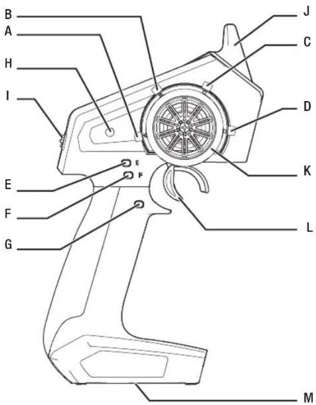
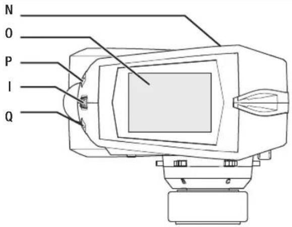
A: Trimmer Button A
Default- Throttle Trim
B: Trimmer Button B
Default- Steering Trim
C: Trimmer Button C
D: Trimmer Button D
E: Trimmer Button E
Default- Steering Rate Up
F: Trimmer Button F
Default- Brake Rate Up
G: Button G
Default- Timer Start/Stop
H: Power Button
I: Roller Wheel
J: Antenna
K: Steering Wheel
L: Trigger (throttle/brake)
M: Battery Door
N: Data Port
0: LCD Screen
P: Back Button
Q: Clear Button
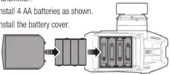
INSTALLING BATTERIES
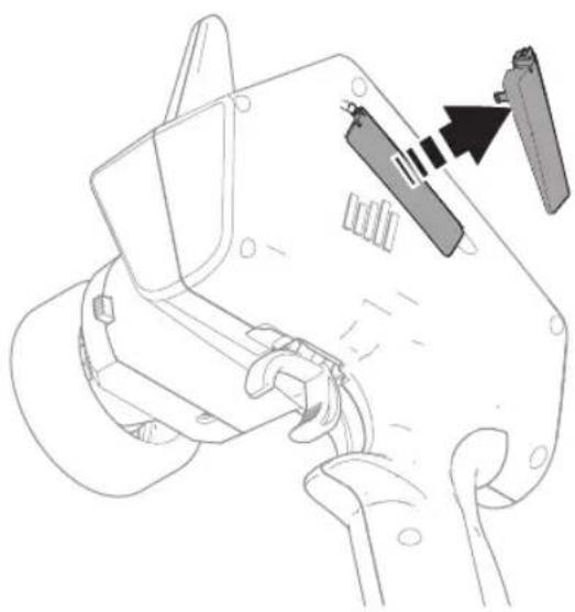
- Remove the battery cover from the bottom of the transmitter.
- Install 4 AA batteries as shown.
- Install the battery cover.
MAIN SCREEN
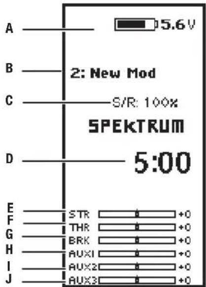
The Main Screen displays information about the active model, including the Timer (when activated). To return to the Main Screen at any time, press and hold the scroll wheel for at least 6 seconds.
A: Transmitter Battery Voltage
B: Model Name
C: Steering Rate
D: Timer (when activated)
E: Position of Steering (STR) trim
F: Position of Throttle (THR) trim
G: Position of Brake (BRK) trim
H: Position of AUX 1 trim
I: Position of AUX 2 trim
J: Position of AUX 3 trim
CAUTION: NEVER remove the transmitter batteries while the model is powered on. Loss of model control, damage or injury may occur.
CAUTION: If using rechargeable batteries, charge only rechargeable batteries. Charging non-rechargeable batteries may cause the batteries to burst, resulting in injury to persons and/or damage to property.
CAUTION: Risk of explosion if battery is replaced by an incorrect type. Dispose of used batteries according to national regulations.
NAVIGATION
USING THE SCROLL WHEEL SELECTOR
- Scroll the scroll wheel to move through the screen content or change programming values. Click the scroll wheel to make a selection.
- Use the Back Button to go back to go to the previous screen (for example, to go from the Mixing Screen to the Function List).
- Use the Clear Button to return a selected value on a screen to the default setting.
- The Main Screen appears when you power on the transmitter. Click the scroll wheel once to display the Function List.
- Scroll from the main screen to view telemetry screens and the servo monitor.

To Enter, Select or Exit a selection.
SCROLL HOLDCLICK
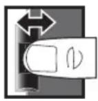
To move between options or change values in an option.

Hold for 6 seconds and release to return to the Main screen.
INDIVIDUAL DIRECTION ADJUSTMENTS
In some instances, you may find it necessary to independently adjust the control directions; for example, if you want more travel for left steering than right steering, perform the following steps:
- Slide to the value you wish to change and press OK
- When both directions are selected, move the control (steering or throttle) toward the control direction you wish to change. The selection box moves to the desired direction. You do not need to hold the control in the desired direction.
- To change the opposite direction, simply move the control in that direction.
- Press OK to save the selection.
AUTO SWITCH SELECT
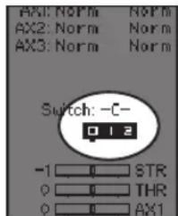
To easily select a switch in a function, such as a program mix, use the slide button to highlight the switch selection box, and press OK. The box around the switch should now flash. To select a switch, toggle the switch you wish to select. Verify the switch selection is now displayed as desired. When correct, press OK to select this switch and complete the switch selection.
Tip: The tick mark below shows the current switch position.
Use the slide button and press OK to turn the selected box black, indicating that the value or condition will act on that position.
SWITCH SELECTION TIP
If the system won't allow INHIBIT to be changed, all switches are assigned to a different function. Un-assign a switch from another function to free it up for selection.
The DX6C does not allow switch assignments to be over-loaded,
there is only one switch to one function. Once a switch is configured for a function, the switch assignment for that function must be disabled for the switch to be used for something else.
CHANNEL MONITOR
If the system won't allow INHIBIT to be changed, all switches are assigned to a different function. Un-assign a switch from another function to free it up for selection.
The DX6C does not allow switch assignments to be over-loaded,
there is only one switch to one function. Once a switch is configured for a function, the switch assignment for that function must be disabled for the switch to be used for something else.
MENU
Click the scroll wheel from the main screen to access the FUNCTION LIST. The FUNCTION LIST contains all the available menus on the DXC+. The functions include:
- Model Select
- Vehicle Type
- Model Name
- Channel Count
- Travel
- Sub Trim
- Reverse
-
Speed
-
Channel Name
- Absolute Travel
- Rates
- Exponential
- Timer
- Bind/ Frame Rate
-
Mixing
• AVC -
Trim Setup
- Channel Assign
- Telemetry
- USB Settings
- Settings
- Utilities
MODEL SELECT
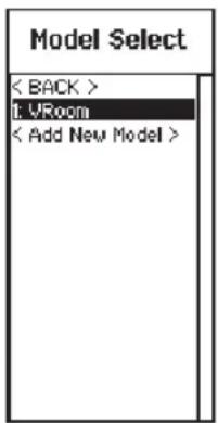
Model Select enables you to access any of the 20 internal model memory locations in the Model Select list.
- Scroll to the desired model memory in the Model Select list.
- When the desired model memory is highlighted, press OK once to select the model. The transmitter returns to the Main Screen.
- Add a new model by rolling to the bottom of the list. You will then be prompted with the Create New Model screen, with the option to create a new model or cancel. If you select Cancel, the system will return to the Model Select function. If you select Create, the new model will be created and now be available in the model select list.

CAUTION: NEVER change the model in Model Select while operating a model. Changing the model memory interrupts the transmitter signal to the receiver and may cause loss of vehicle control, damage or personal injury.
VEHICLE TYPE
Vehicle Type enables you to operate SLT vehicles with preset model configurations designed to match the settings found in RTR SLT transmitters.
To add select the Vehicle Type:
- Select the desired SLT mode to match your model.
- The model file configuration will set for the model needs (SLT Basic, SLT with DSC, or SLT with 4WS)
- Select Model Reset to remove Vehicle Type settings

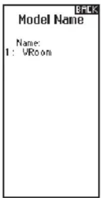
MODEL NAME
Model Name enables you to assign a custom name to the current model memory. Model names can include up to 15 characters, including spaces.
To add letters to a Model Name:
- Slide to the desired letter position and press OK. A flashing box appears.
- Slide Up or Down until the desired character appears. Press OK to save the character.
- Slide to the next desired letter position. Repeat Steps 1 and 2 until the Model Name is complete.
- Select Back Button to return to the MENU.
To erase a character(s):
- Press the Clear button while the character is selected.
- Press the Clear button a second time to erase all characters to the right of the cursor.
MENU
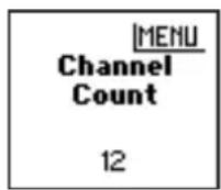
CHANNEL COUNT
Channel count controls the number of channels available for the selected model file. Select 2 to 12 channels.
TRAVEL
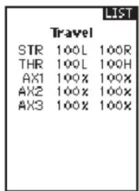
The Servo Setup menu contains the following functions:
Travel sets the overall travel or endpoints of the servo arm movement. Travel values range from 0–150% (Default is 100%).
To adjust Travel values:
- Slide to the channel you wish to adjust and press OK.
- Slide Up or Down to adjust the travel value. Press OK to save the selection.
SUB-TRIM
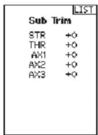
Subtrim offsets the entire range of servo travel including the center and endpoint positions.

CAUTION Use only small sub-trim values may affect travel if full servo travel is used.
REVERSE
Use the Reverse menu to reverse the channel direction. For example, if the Steering servo moves Left, reversing the channel will move the Steering servo Right.
To reverse a channel direction:
- Slide to Travel and press OK. Slide up or down until Reverse appears, then press OK again to save the selection.
- Slide to the channel you wish to reverse and press OK.
If you reverse the Throttle channel, a confirmation screen appears. Select YES to reverse the channel. A second screen appears, reminding you to bind your transmitter and receiver.
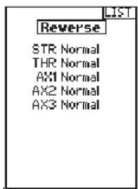

CAUTION: Always rebind the transmitter and receiver after reversing the Throttle channel. Failure to do so will result in the throttle moving to full throttle if failsafe activates.
Always perform a control test after making adjustments to confirm the vehicle responds properly.

CAUTION: After adjusting servos, always rebind the transmitter and receiver to set the failsafe position.
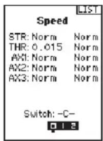
SPEED
The Speed menu enables you to slow the response time on any individual channel.
The Speed is adjustable from 100% to 1%.
To adjust the Speed:
- Slide to the channel you wish to adjust and press OK.
- Slide Up or Down to adjust the speed and press OK to save the selection.
- Select a switch to activate/deactivate the function. If Switch ON is selected, the value will always be on for that function.
MENU
CHANNEL NAME
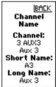
Channel name functions enable the driver to assign a name to each channel.
To change the Channel Name:
- From the Channel Name menu select the channel and a sub menu with appear.
- Channel tells you which channel you are changing, Short Name is the abbreviated name which will be used in limited space, and Long Name is the full description when space is available.
ABSOLUTE TRAVEL
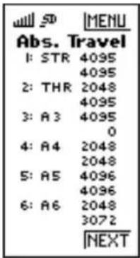
The Abs. Travel function limits the amount of travel on a channel. Adjust the Abs. Travel value to prevent a servo from binding when a mix is applied.
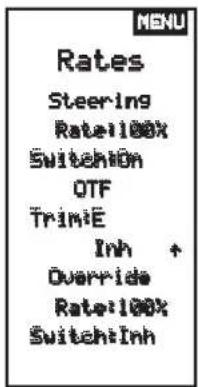
RATES
Rates allow the driver to reduce the travel (0-100%) of the Steering, Throttle, or Braking with a trimmer button. The Override option allows drivers to select a different rate value (0-125%) while holding down the assigned trimmer button. This is especially helpful for oval racers that program minimal steering throw to desensitize steering during racing, but requires maximum steering angle to drive out of a crash or get turned around on the track.
To adjust Rate values:
- Slide to Steering and press OK to select between Steering, Throttle or Brake.
- Slide Up or Down to adjust the Rate value. Press OK to save the selection.
- Set the Switch setting to On to enable Rates, select Inh to disable Rates.
- Select an Override rate and switch.
- Select the OTF (On-The-Fly) trimmer that will be used to adjust Rates On-The-Fly.
TIP: In order for the OVERRIDE to operate, you must assign it to a switch or trimmer. The default position for this function is inhibited.
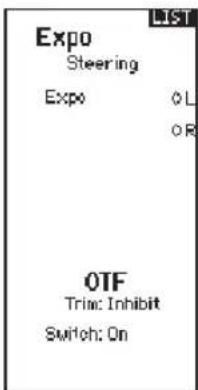
EXPONENTIAL
The Exponential (Expo) function affects the response rate of the steering, throttle and/or brake. A positive Steering Expo value, for example, decreases steering sensitivity around neutral to make it easier to drive at high speeds in a straight line while still allowing for maximum turning radius. While sensitivity with positive Expo is decreased around neutral, it increases the sensitivity near the end of travel.
To adjust Expo values:
- Select Throttle or Steering.
- Slide Up or Down to adjust the Rate value.
- Press OK to save the selection.
- Select an OTF switch to activate Exponential.
IMPORTANT: Both positive and negative Expo values are available. A positive Expo value results in the center being less sensitive (desirable most of the time), while a negative value increases the sensitivity around center (normally not used).
MENU
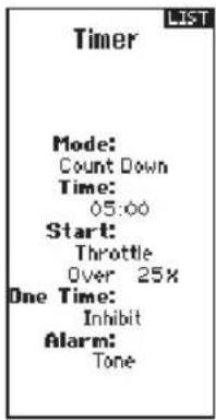
TIMER
The DX6C Timer function allows you to program a countdown timer and stop watch (count up timer) to display on the main screen. An alarm sounds when the programmed time is reached. You can program the timer to start using the assigned switch position or automatically when the throttle moves above a pre-programmed position.
BIND/FRAME MENU
For compatibility with all types of servos, three frame rates are available:
- DSMR 5.5: Offers good response rates and is compatible with most digital. Works with DSMR® surface receivers.
- DSMR: Default setting, needed for older analog servos. Works with DSMR® surface receivers.
- DSMR+: Used for high channel count systems, up to 12 channels. Works with DSMR+® surface receivers.
- SLT: Used to bind with ready to run vehicles with SLT® technology.
IMPORTANT: Always rebind after changing the Frame Rate.
Failsafe
In the unlikely event that the radio link is lost during use, the receiver will drive the throttle servo to its pre-programmed failsafe position (normally full brakes) and all other channels will have no servo output. The throttle failsafe position is set during binding. If the receiver is turned on prior to turning on the transmitter, the receiver will enter the failsafe mode, driving the throttle servo to its preset failsafe position. When the transmitter is turned on, normal control is resumed.
IMPORTANT: failsafe activates only in the event that signal is lost from the transmitter. Failsafe will NOT activate in the event that receiver battery power decreases below the recommended minimums or power to the receiver is lost.
NOTICE: AVC receivers must be calibrated after binding for proper operation.
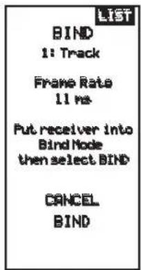
Binding
Binding is the Process of teaching the receiver the specific transmitter's code called GUID (Globally Unique Identifier) and storing failsafe values. When a receiver is bound to a transmitter/model memory, the receiver will only respond to that specific transmitter/model memory.
Bind Process
- Use a bind plug or press the bind button to place the receiver into Bind mode. The LED on the receiver will begin to flash.
- Power on the transmitter.
- Select the Model Memory you wish to bind to.
- Select Bind from the List menu.
- Move the throttle channel to the desired failsafe position.
NOTICE: The throttle channel must stay in the failsafe position until binding is complete.
- Slide to Bind and press OK. The orange LED flashes on top of the transmitter.
- When the bind process is complete, the transmitter and receiver LEDs stop flashing and turn solid orange.
- Remove the bind plug from the receiver and keep it in a convenient place.
IMPORTANT: Always remove the bind plug from the receiver when the bind Process is complete. Failure to do so will cause the receiver to enter bind mode the next time you power on the receiver.
MENU
MIXING
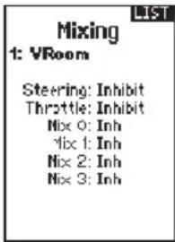
Mixes can connect two servo outputs to one control input. The DX6C features preset steering mixes and one programmable mix (Mix 0). The AUX channels can only be assigned to one mix at a time. If AUX 1, 2, or 3 is assigned to another mix, it will not be available as a slave channel option. AUX channels 1 and 2 are not available for use in mixes when the AVC menu in the transmitter is active.
STEERING MIX
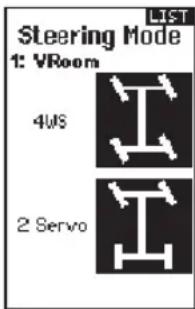
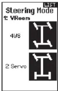
The pre-configured Steering Mix options are for vehicles using two steering servos. For vehicles with servos independently controlling front and rear wheels, four-wheel steering (4WS) offers four different mixing options on one switch. The dual steering servo (Dual ST) mix is for vehicles with two servos working together on the front wheels.
4WS (4-Wheel Steering)
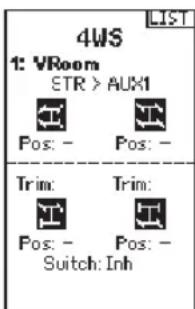
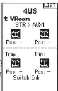
4WS options in the DX6C offer four different steering configurations using one switch; Crab, 4WS, front only, and rear only steering.
- Select 4WS and press OK.
- To activate, select Inhibit and slide to select the second steering channel. Select STR > AUX 1 and slide to choose from AUX 1, AUX 2 or AUX 3 as the second steering (slave) channel.
- Assign a switch or set the switch assignment to ON.
- Each of the four steering options each needs to be assigned to a switch position to be enabled. Crab and 4WS options also need to have rates assigned.
- Select Pos: and use the slide button to select the switch position (0-3). After the switch positions are assigned to the steering modes, the current switch selection will be indicated with a box around the steering mode.
-
For Crab and 4WS steering, a set of travel settings and a trim option for the second servo appear when the switch position setting (Pos: ) is assigned to a switch position. Front only and Rear only steering options do not have rate or trim options.
-
Use the slide button to select the travel settings, turn the wheel to adjust travel for each side individually. Setting this value positive or negative determines the second servo direction.
- Use the slide button to select the Trim option. Select active (Act) to carry over trim settings to the mixed (slave) steering channel. Leave Inh if the trim should only adjust the primary steering channel.
2 Servo (Dual Steering)
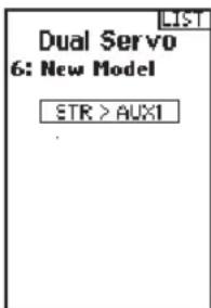
- Select STEERING in the Mixing screen and press OK.
- Select 2 SERVO and press OK.
- To activate, select Inhibit and slide to select STR > AUX 1. Select AUX 1, AUX 2 or AUX 3 for the second steering (slave) channel.
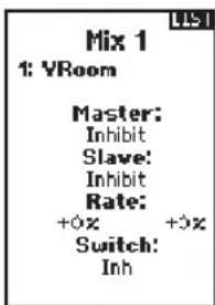
PROGRAMMABLE MIX
A freely assignable mix allows drivers to set up a second (Slave) channel to follow a primary (Master) channel.
- Select Mix O and press OK. In the mixing menu, select Mix O to rename the mix.
- To activate, select a Master and Slave channel and assign the Rate.
- Select Inhibit under Master and slide to select the Master (input) channel.
- Select Inhibit under Slave and slide to select the Slave (output) channel.
- Rate settings define travel limits and direction. Move the input channel (steering wheel, throttle, or whatever function is assigned to the master channel) to adjust the rate for each side of the slave channel travel. Setting this value positive or negative determines the slave servo direction.
-
Select Switch; Inh will disable the mix, ON will activate the mix, or a switch can be assigned to turn the mix on and off.
-
Set Trim to Act or Inh (Default). When Trim is Active, adjustments to the Master trim carries over to the Slave channel.
MENU
AVC PROGRAMMING MENU
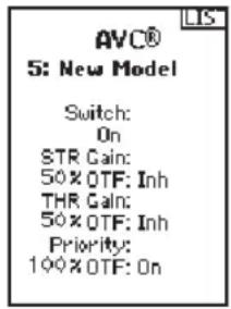
The DX6C includes a menu specific to AVC operation. This menu manages AUX 1 and AUX 2 operation and tailors it for AVC® technology use. The AVC menu also controls the Priority features. See page 18 for more information on AVC tuning
To activate the AVC menu:
- Select AVC in the main menu
- Select Switch and use the slide button to select On to enable the AVC menu.
-
Change the gain and priority values to suit the vehicle.
-
To fine tune each value during use without having to access the programming menu, assign a trimmer to the On-The-Fly (OTF) feature for each AVC value.
Select the arrow to the right of the switch selection to set the trimmer to increase or decrease the gain from the set value.
Tip: Trimmers can only be assigned to one OTF function; Steering and throttle gain values cannot be adjusted from one trimmer button.
TIP: For receivers without AVC, leave the AVC menu in theDX6C inhibited (INH).
TRIM SETUP
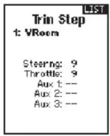
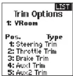
Trim Setup affects the amount the servo travels with each click of the trim, but has no effect on the total trim travel. The trim steps range from 1 to 20 (Default is 9).
To adjust the trim steps:
- Select channels to edit.
- Slide Up or Down to adjust the step value.
- Press OK to save the selection.
TRIM ASSIGN
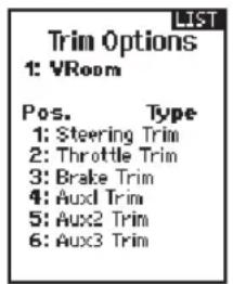
Trim ASSIGN allows for the assigning of a switch to the Steering or Throttle trims.
- From within Trim Setup, select NEXT.
- Select channels to assign a switch to.
- Slide Up/Down or toggle a switch/button to assign.
- Press OK to save the selection.
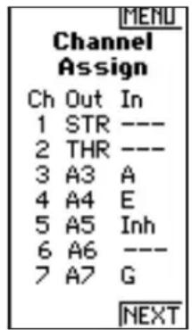
CHANNEL ASSIGN
Channel Assign allows for the assigning of a switch or trimmer as input to an AUX channel.
Channel assign:
- Select a channel to edit. Press OK to save the selection.
- Slide Up/Down or toggle a switch/button to assign.
- Press OK to save the selection.
MENU
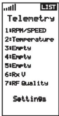
TELEMETRY
The telemetry screen allows for easy access to all telemetry sensors and settings.
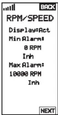
To edit telemetry sensors:
- Select the sensor from the list.
- Press OK to open that sensors settings.
- Adjust sensor parameters.
- Press OK to save the selection.
Settings: Chose how telemetry is displayed on the transmitter.
File Settings:
- Displays File name of saved telemetry files.
- Inhibit, activate telemetry file saving.
SMART Throttle\*:
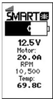
The new line of Spektrum ESCs feature a telemetry function called SMART Throttle. SMART Throttle technology combines the throttle signal with telemetry data from the ESC on one normal three wire servo connector.
SMART Throttle ESCs can send current, voltage, ESC temp, and mAh consumed. They can also pass along battery data from compatible Spektrum SMART batteries. SMART Throttle telemetry data shows up on your transmitter like any other telemetry sensor.
For SMART Throttle to function you must have a compatible Spektrum ESC, and telemetry receiver to pair with your DX6C. Only certain Spektrum products include SMART technology compatibility, check your receiver and ESC manual for more information.
To view SMART Telemetry:
- The vehicle needs to powered on with the receiver connected to the transmitter
- Scroll down while on the main screen
- SMART telemetry screens will appear after the monitor screen.
To activate Speed information using SMART Telemetry:
- The vehicle needs to powered on with the receiver connected to the transmitter
- Scroll to the Telemetry screen
- Scroll to SMART ESC and double select
- Scroll down to NEXT
- Enter the values for the magnetic pole count of the motor, and roll out.
- Change the display to SPEED (motor and roll out information can be found in the manual for your vehicle)
When the radio is on and connected to a receiver sending SMART Data, the SMART Logo will appear under the battery logo on the home page and a signal bar will appear in the top left corner of the screen.
USB SETTINGS
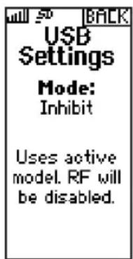
The DX6C can operate as a game controller on a PC when connected to the USB port. When this mode is set to Inhibit the transmitter will operate normally. When the mode is set to Active the transmitter will not transmit (RF is off and the transmitter does not connect or bind with a receiver). We recommend setting up a model file specifically for game controller use.

CAUTION: NEVER change the USB mode to Active when the transmitter is controlling a vehicle, the transmitter will no longer send a signal and the vehicle will go into failsafe mode.
MENU
SETTINGS
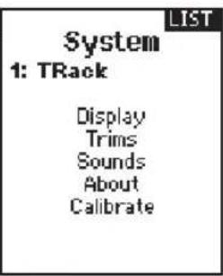
System settings allow adjustments to the following transmitter settings:
- Display
- Sounds
- Calibrate
- Trims
- About
- Battery
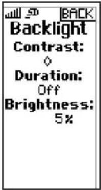
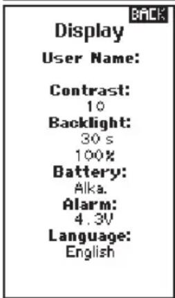
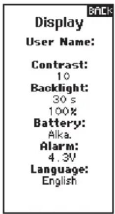
Display
Contrast
To adjust the screen contrast:
- Slide to Contrast and click the scroll wheel.
- Slide Up or Down to adjust the contrast value. Lower numbers lighten the contrast, higher numbers darken it.
- Press OK once to save the selection.
Duration
On-time ("Duration") has values Off, On, 3s, 10s, 20s, 30s, 45s, and 60s (in that order), and defaults to 30s. On and Off hold the backlight in that state, whereas the others will turn the backlight off after a period of time since the last user input.
Brightness
Values in the range 5% to 100% in 5% steps, and defaults to 100%.
User Name
The User Name field displays the user name above the model name on the main screen.
- Slide to the desired letter position and click the scroll wheel once. A flashing box appears.
- Slide Up or Down until the desired character appears. Press OK once to save the character.
- Slide to the next desired letter position. Repeat Steps 1 and 2 until the Model Name is complete.
Language:
Change the transmitter's language. The transmitter will retain the language for models already created.
New models will be created using the currently selected language.
Inactive Alarm:
An alarm activates if the transmitter sees a period of inactivity for a certain amount of time. The alarm is helpful in reminding you to power off the transmitter and avoiding a situation where the transmitter battery completely discharges.
- Inh (No alarm sounds)
- 10 min (Default)
- 60 min
- 5 min
• 30 min
MENU
SYSTEM SETTINGS (CONTINUED)
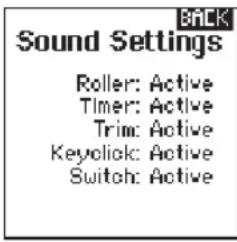
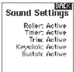
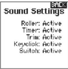
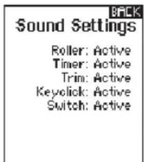
Sound settings
Turn system sounds ON/OFF.
- Select the sound from the list.
- Press OK once to Activate/Inhibit.
- Press OK to save the selection.
About
Displays the transmitter's Serial Number. Start a user account at SpektrumRC.com and enter the serial number displayed on the About page register the transmitter.
CALIBRATE
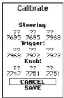
Use this menu to calibrate controls. After making physical changes to the transmitter, such as changing the wheel, calibrate the transmitter.
- Move the Steering Wheel, Throttle/Brake and the knob from stop to stop.
- Save when finished or cancel to go back.
SYSTEM SETUP
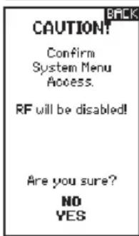
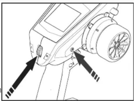
Press and hold the slide button while powering on the transmitter to show the System Setup list. No radio transmission occurs when a System Setup screen is displayed, preventing accidental damage to linkages and servos during changes to programming.
The System Setup menu can also be accessed from the Function list. A CAUTION screen will appear that warns that RF will be disabled (the transmitter will no longer transmit). Press YES to access the System List. If no selection is made, the system will exit to the main screen within approximately 10 seconds.
natural_image
Technical line drawing of a mechanical component with arrows indicating assembly or alignment (no text or symbols)
WARNING: Do not press YES to enter the Utilities menu unless the model is turned off and secured.
MODEL SELECT
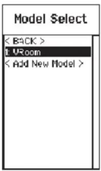
Model Select enables you to access any of the 20 internal model memory locations in the Model Select list.
- Slide to the desired model memory in the Model Select list.
- When the desired model memory is highlighted, press OK to select the model. The transmitter returns to the Main Screen.
- Add a new model by rolling to the bottom of the list. You will then be prompted with the Create New Model screen.

CAUTION: NEVER change the model in Model Select while operating a model. Changing the model memory interrupts the transmitter signal to the receiver and may cause loss of vehicle control, damage or personal injury.
MODEL UTILITIES
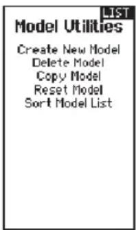
In the Model Utilities function you can create a new model, delete a model, copy a model, reset a model to default settings and sort the model list. If the DX6C is updated, use the Validate All selection to ensure model settings are updated to be fully compatible with the new firmware. The Delete All selection will delete all model settings.
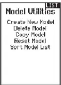
UTILITIES
MODEL UTILITIES (CONTINUED)
Create New Model
- Select the CREATE NEW MODEL and click the scroll wheel.
- Select CREATE to create a new model or CANCEL to go back.
- The new model is available in the model select list.

CAUTION: NEVER change the model in Model Select while operating a model. Changing the model memory interrupts the transmitter signal to the receiver and may cause loss of vehicle control, damage of personal injury.
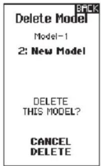
Delete Model
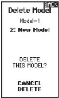
Use this selection to permanently delete a model from the model select list. If you do not wish to delete a model, select Cancel to exit the page.
- To delete a model, highlight the model listed. Press OK, then slide to the model name. Press OK to select the model.
- Select DELETE to delete the model.
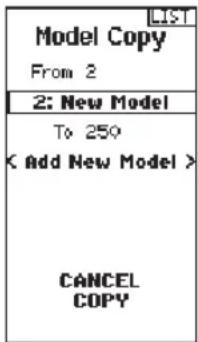
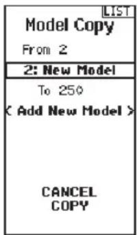
Model copy
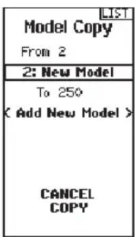
The Model Copy menu enables you to duplicate model programming from one Model List location to another. Use Model Copy to:
- Save a default model copy before experimenting with programming values
- Expedite programming for a model using a similar programming setup
IMPORTANT: Copying a model program from one model memory to another will erase any programming in the "To" model memory.
To copy model programming:
- Select where to save the copied memory by selecting "TO" and scroll to ADD NEW MODEL. Press OK to save the selection. To save over a current model, select that model from the list.
- Select the model to be copied by selecting "From" and slide to the model to be copied.
- Slide down to COPY at the bottom of the screen and press OK.
- Confirm the copy by selecting COPY or CANCEL to go back.
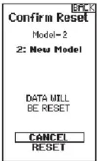
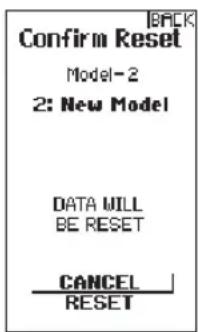
Reset Model
Use the Model Reset menu to delete all model programming in the active model memory. Reset returns all model settings to the default settings and erases all programming in the selected model.
IMPORTANT: After a model reset, it is necessary to re-bind.
Sort Model List
With this function you can sort the model order in the model select function. This is helpful to group similar models together to make them easy to find. To move a model, highlight the model that you wish to move with the slide button, then press OK to select it. Use the slide button to move the selected model to the position desired. Press OK when you have the model in the position desired.
PHYSICAL TRANSMITTER ADJUSTMENTS
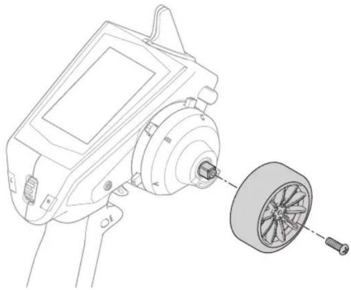
STANDARD WHEEL CONVERSION
• Using a 1.5mm hex wrench, remove the steering wheel.
• Re-install the steering wheel.
natural_image
Technical line drawing of a mechanical device with a close-up view of its internal components (no text or symbols)STEERING TENSION ADJUSTMENT
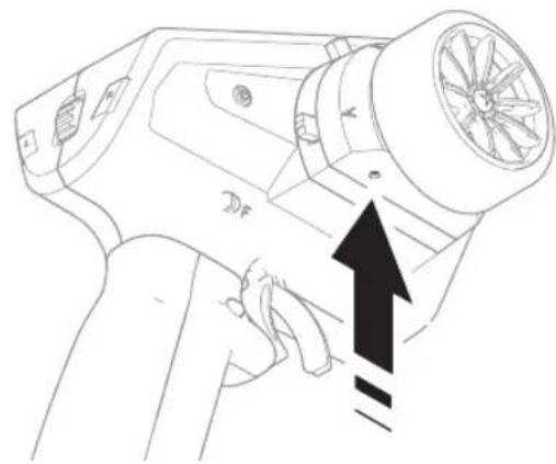
Turn the screw clockwise with a small Phillips screw driver to increase the steering tension.
natural_image
Line drawing of a handheld hair dryer with a black upward arrow indicating motion (no text or symbols)DATA PORT
The data port gives drivers access to future updates. Registering the transmitter is necessary for updates. Updates require a micro USB cable (not included, PC required).
The micro USB port is only for updates, it cannot be used to charge the transmitter battery.
natural_image
Technical line drawing of a vehicle's front wheel assembly with a close-up inset showing the blade and handle (no text or symbols)AVC TUNING (AVC RECEIVER NOT INCLUDED)
A value from 0 to 100 is used for three settings that affect tuning; steering gain, throttle gain, and priority. These values configure the receiver to your vehicle so you can tune it for optimal performance based on your driving style. It is normal for gain and priority tuning results to vary.
WHAT IS GAIN?
A gain value of 0 will result in zero electronic corrections, and a gain of 100 will result in large corrections in an effort to hold a straight line.
• Steering gain tells the receiver how strongly to assist steering when the vehicle begins to spin out of control.
- Throttle gain tells the receiver how much it can assist on the throttle when the vehicle begins to spin out of control.
Default gain values are 50. We recommend adjusting gain values 5 points at a time. Fine tune the settings with smaller increments as desired performance is achieved. Avoid large increases to steering gain values between tests.
WHAT IS PRIORITY?
Priority tells the receiver how much you want to be able to override the electronic stability with your steering commands. A low priority means AVC will make steering corrections when you turn wheel all the way. A high priority will reduce AVC the more you turn the wheel.
The default priority value is 100. This means when you turn the steering wheel to the limit, the gain is reduced to zero. This value will work well for a majority of drivers
WHAT IS HEADING HOLD?
Heading hold maintains the selected vehicle direction. It is normal to see the wheels steer in the same direction it was last pointed. If a vehicle with AVC technology is lifted off the ground and turned from side to side, the wheels will steer in an effort to get back to the original heading. When driving, heading hold only works when the steering wheel is left straight. The moment you begin to turn the wheel, heading hold turns off. When the wheel is re-centered, heading hold is turned back on.
AVC TUNING PROCEDURE
- With the transmitter and receiver already bound and properly calibrated, turn on the transmitter and vehicle.
-
Apply throttle, do not turn the steering wheel, and observe how well the vehicle can maintain a straight line at high speed.
-
If the vehicle does not make enough steering corrections to maintain a straight line, increase the steering gain. If the vehicle fishtails due to wheel-spin, increase the throttle gain.
- If the vehicle wobbles (oscillates), reduce the steering gain.
The maximum gain values that prevent oscillations at high speed should not be exceeded.
-
Drive the vehicle through accelerated turns and observe how it responds.
-
If the vehicle slows down going into a turn, reduce the throttle gain.
- To allow the vehicle to slide more with intentional wheel-spin, reduce the throttle gain.
- To improve traction in slick conditions, increase throttle gain.
- If the vehicle won't turn-in, increase the priority.
-
If the vehicle spins out, there are two tuning options to consider;
-
Increasing throttle gain will help correct for undesirable wheel-spin when the vehicle over-rotates.
- Reducing priority will give the receiver more authority to help correct oversteer.
GENERAL TUNING TIPS
For beginner drivers, looser conditions, and vehicles with excessive power, more gain will be helpful.
For terrain with more grip and increased speeds, tuning will result in lower steering gain values.
NOTICE: If you adjust the steering and throttle trim on your transmitter, the receiver must be turned off and back on again in order to save the new trim settings. Otherwise, AVC will not function properly.
CHANGING BATTERY VOLTAGE
If the voltage is increased, the maximum steering gain setting will have to be reduced.
At the same time, when increasing voltage, increased throttle gain will help manage the extra power.
For example: If a truck set up for 2S is upgraded to 3S, the truck may oscillate at high speeds on 3S, requiring steering gain to be reduced. Throttle gain will have a bigger effect on 3S, so increasing throttle gain may be beneficial.
TROUBLESHOOTING GUIDE
PROBLEM POSSIBLE CAUSE SOLUTION
| The system will not connect | Transmitter and receiver too near each other | Move transmitter 8 to 12 feet (2.4 to 3.6m) from receiver |
| Transmitter and receiver too near large metal objects (vehicles, etc.) | Move away from large metal objects (vehicles, etc.) | |
| Selected model is not bound in transmitter | Make sure correct model memory is selected and that transmitter is bound to the model | |
| Transmitter accidentally put in bind mode so receiver is no longer bound | Rebind transmitter and receiver | |
| Bind plug left installed in bind port | Rebind transmitter to the vehicle and remove the bind plug before cycling power | |
| Vehicle battery/Transmitter battery charge is too low | Replace/recharge batteries | |
| The receiver goes into failsafe mode a short distance away from the transmitter | Check the receiver antenna to be sure it is not cut or damaged | Replace or contact Horizon product Support |
| Make sure receiver antenna is in an antenna tube and is above vehicle | ||
| Receiver quits responding during operation | Low battery voltage Completely recharge battery | |
| Loose or damaged wires or connectors between battery and receiver | Do a check of the wires and connection between battery and receiver. Repair or replace wires and/or connectors | |
| Receiver loses its bind | Transmitter accidentally put in bind mode, ending bind to receiver | Bind transmitter to receiver |
| Can't assign functions to the desired switches or buttons | Buttons and/or switches are already assigned to another function | Re-assign functions to other buttons or switches to free up the switch so it can be assigned to your designated function |
| Function requires a switch or trimmer, but-tons have limited functionality | Select a switch or trimmer if your designated function will not work with a button. |
AVC TROUBLESHOOTING GUIDE
PROBLEM POSSIBLE CAUSE SOLUTION
| Vehicle Oscillates (wobbles or shakes) at high speeds | Steering gain is too high Reduce steering gain | |
| Vehicle responds strangely to controls | Receiver not properly calibrated | Confirm servo direction and travel are correct, then re-bind and re-calibrate the receiver |
| Vehicle setup changed after calibration | ||
| Receiver not mounted level | Confirm the receiver is truly flat, it cannot be mounted at an odd angle. | |
| Receiver won’t finish the calibration | Travel adjust is below 80% on steering or throttle | Increase travel adjust and recalibrate. See page 19 for more information about setting up vehicles with a mechanical brake. |
| Driver expects AVC should be turned off, but it is still turned on | AVC menu is inhibited, but AUX values are at neutral, which works out to 50% gain but with no priority. | Bind with second bind plug in the disable port, or change AVC menu to on and set all gain values to 0 |
| Second bind plug to disable AVC was inserted after binding | Re-bind with the second bind plug in the disable port |
OPTIONAL PARTS LIST
PART # PARTS DESCRIPTION
SPM6719 Spektrum DX6R Transmitter Case
Additional optional parts and details are available at SpektrumRC.com
1-YEAR LIMITED WARRANTY
What this Warranty Covers
Horizon Hobby, LLC, (Horizon) warrants to the original purchaser that the product purchased (the "Product") will be free from defects in materials and workmanship for a period of 1 year from the date of purchase.
What is Not Covered
This warranty is not transferable and does not cover (i) cosmetic damage, (ii) damage due to acts of God, accident, misuse, abuse, negligence, commercial use, or due to improper use, installation, operation or maintenance, (iii) modification of or to any part of the Product, (iv) attempted service by anyone other than a Horizon Hobby authorized service center, (v) Product not purchased from an authorized Horizon dealer, (vi) Product not compliant with applicable technical regulations or (vii) use that violates any applicable laws, rules, or regulations.
OTHER THAN THE EXPRESS WARRANTY ABOVE, HORIZON MAKES NO OTHER WARRANTY OR REPRESENTATION, AND HEREBY DISCLAIMS ANY AND ALL IMPLIED WARRANTIES, INCLUDING, WITHOUT LIMITATION, THE IMPLIED WARRANTIES OF NON-INFRINGEMENT, MERCHANTABILITY AND FITNESS FOR A PARTICULAR PURPOSE. THE PURCHASER ACKNOWLEDGES THAT THEY ALONE HAVE DETERMINED THAT THE PRODUCT WILL SUITABLY MEET THE REQUIREMENTS OF THE PURCHASER'S INTENDED USE.
Purchaser's Remedy
Horizon's sole obligation and purchaser's sole and exclusive remedy shall be that Horizon will, at its option, either (i) service, or (ii) replace, any Product determined by Horizon to be defective. Horizon reserves the right to inspect any and all Product(s) involved in a warranty claim. Service or replacement decisions are at the sole discretion of Horizon. Proof of purchase is required for all warranty claims. SERVICE OR REPLACEMENT AS PROVIDED UNDER THIS WARRANTY IS THE PURCHASER'S SOLE AND EXCLUSIVE REMEDY.
Limitation of Liability
HORIZON SHALL NOT BE LIABLE FOR SPECIAL, INDIRECT, INCIDENTAL OR CONSEQUENTIAL DAMAGES, LOSS OF PROFITS OR PRODUCTION OR COMMERCIAL LOSS IN ANY WAY, REGARDLESS OF WHETHER SUCH CLAIM IS BASED IN CONTRACT, WARRANTY, TORT, NEGLIGENCE, STRICT LIABILITY OR ANY OTHER THEORY OF LIABILITY, EVEN IF HORIZON HAS BEEN ADVISED OF THE POSSIBILITY OF SUCH DAMAGES. Further, in no event shall the liability of Horizon exceed the individual price of the Product on which liability is asserted. As Horizon has no control over use, setup, final assembly, modification or misuse, no liability shall be assumed nor accepted for any resulting damage or injury. By the act of use, setup or assembly, the user accepts all resulting liability. If you as the purchaser or user are not prepared to accept the liability associated with the use of the Product, purchaser is advised to return the Product immediately in new and unused condition to the place of purchase.
Law
These terms are governed by Illinois law (without regard to conflict of law principals). This warranty gives you specific legal rights, and you may also have other rights which vary from state to state. Horizon reserves the right to change or modify this warranty at any time without notice.
WARRANTY SERVICES
Questions, Assistance, and Services
Your local hobby store and/or place of purchase cannot provide warranty support or service. Once assembly, setup or use of the Product has been started, you must contact your local distributor or Horizon directly. This will enable Horizon to better answer your questions and service you in the event that you may need any assistance. For questions or assistance, please visit our website at www.horizonhobby.com, submit a Product Support Inquiry, or call the toll free telephone number referenced in the Warranty and Service Contact Information section to speak with a Product Support representative.
Inspection or Services
If this Product needs to be inspected or serviced and is compliant in the country you live and use the Product in, please use the Horizon Online Service Request submission process found on our website or call Horizon to obtain a Return Merchandise Authorization (RMA) number. Pack the Product securely using a shipping carton. Please note that original boxes may be included, but are not designed to withstand the rigors of shipping without additional protection. Ship via a carrier that provides tracking and insurance for lost or damaged parcels, as Horizon is not responsible for merchandise until it arrives and is accepted at our facility. An Online Service Request is available at http://www.horizonhobby.com/content/_service-centerRender-service-center. If you do not have internet access, please contact Horizon Product Support to obtain a RMA number along with instructions for submitting your product for service. When calling Horizon, you will be asked to provide your complete name, street address, email address and phone number where you can be reached during business hours. When sending product into Horizon, please include your RMA number, a list of the included items, and a brief summary of the problem. A copy of your original sales receipt must be included for warranty consideration. Be sure your name, address, and RMA number are clearly written on the outside of the shipping carton.
NOTICE: Do not ship LiPo batteries to Horizon. If you have any issue with a LiPo battery, please contact the appropriate Horizon Product Support office.
Warranty Requirements
For Warranty consideration, you must include your original sales receipt verifying the proof-of-purchase date. Provided warranty conditions have been met, your Product will be serviced or replaced free of charge. Service or replacement decisions are at the sole discretion of Horizon.
Non-Warranty Service
Should your service not be covered by warranty, service will be completed and payment will be required without notification or estimate of the expense unless the expense exceeds 50% of the retail purchase cost. By submitting the item for service you are agreeing to payment of the service without notification. Service estimates are available upon request. You must include this request with your item submitted for service. Non-warranty service estimates will be billed a minimum of 12 hour of labor. In addition you will be billed for return freight. Horizon accepts money orders and cashier's checks, as well as Visa, MasterCard, American Express, and Discover cards. By submitting any item to Horizon for service, you are agreeing to Horizon's Terms and Conditions found on our website http://www.horizonhobby.com/content/_service-center_render-service-center.
ATTENTION: Horizon service is limited to Product compliant in the country of use and ownership. If received, a non-compliant Product will not be serviced. Further, the sender will be responsible for arranging return shipment of the un-serviced Product, through a carrier of the sender's choice and at the sender's expense. Horizon will hold non-compliant Product for a period of 60 days from notification, after which it will be discarded.
10-15
WARRANTY AND SERVICE CONTACT INFORMATION
| Country of Purchase | Horizon Hobby Contact Information Address | |||
| United States of America | Horizon Service Center (Repairs and Repair Requests) | servicecenter.horizonhobby.com/RequestForm/ | 2904 Research Road Champaign, Illinois, 61822 USA | |
| Horizon Product Support (Product Technical Assistance) | productsupport@horizonhobby.com | |||
| 877-504-0233 | ||||
| Sales | websales@horizonhobby.com | |||
| 800-338-4639 | ||||
| EU | Horizon Technischer Service service@horizonhobby.de | Hanskampring 9 D 22885 Barsbüttel, Germany | ||
| Sales: Horizon Hobby GmbH +49 (0) 4121 2655 100 | ||||
FCC INFORMATION
SPMR6130 Transmitter only: Contains FCC ID: BRWPLAN01T
This equipment complies with FCC and IC radiation exposure limits set forth for an uncontrolled environment. This equipment should be installed and operated with minimum distance 20cm between the radiator and/or antenna and your body (excluding fingers, hands, wrists, ankles and feet). This transmitter must not be co-located or operating in conjunction with any other antenna or transmitter..
Supplier's Declaration of Conformity

This device complies with part 15 of the FCC Rules. Operation is subject to the following two conditions: (1) This device may not cause harmful interference, and (2)
this device must accept any interference received, including interference that may cause undesired operation.

CAUTION: Changes or modifications not expressly approved by the party responsible for compliance could void the user's authority to operate the equipment.
NOTE: This equipment has been tested and found to comply with the limits for a Class B digital device, pursuant to part 15 of the FCC Rules. These limits are designed to provide reasonable protection against harmful interference in a
residential installation. This equipment generates, uses and can radiate radio frequency energy and, if not installed and used in accordance with the instructions, may cause harmful interference to radio communications. However, there is no guarantee that interference will not occur in a particular installation. If this equipment does cause harmful interference to radio or television reception, which can be determined by turning the equipment off and on, the user is encouraged to try to correct the interference by one or more of the following measures:
- Reorient or relocate the receiving antenna.
- Increase the separation between the equipment and receiver.
- Connect the equipment into an outlet on a circuit different from that to which the receiver is connected.
- Consult the dealer or an experienced radio/TV technician for help.
Horizon Hobby, LLC
2904 Research Rd.
Champaign, IL 61822
Email: compliance@horizonhobby.com
Web: HorizonHobby.com
IC INFORMATION
CAN ICES-3 (B)/NMB-3(B)
SPMR6130 Transmitter only: Contains IC: 6157A-PLAN01T
This device complies with Industry Canada license-exempt RSS standard(s). Operation is subject to the following two conditions:
(1) this device may not cause interference, and
(2) this device must accept any interference, Including interference that may cause undesired operation of the device.
COMPLIANCE INFORMATION FOR THE EUROPEAN UNION

EU Compliance Statement: Spektrum DXC+ Transmitter Only (SPMR6130),
Hereby, Horizon Hobby, LLC declares that the
device is in compliance with the following: Radio Equipment Directive (RED) 2014/53/EU; RoHS 2 Directive 2011/65/EU; RoHS 3 Directive - Amending 2011/65/EU Annex II 2015/863.
The full text of the EU declaration of conformity is available at the following internet address: https://www.horizonhobby.com/content/support-render-compliance.
Wireless Frequency Range and Wireless Output Power:
DXC+: 2402 - 2478 MHz / 20dBm
EU Manufacturer of Record:
Horizon Hobby, LLC
2904 Research Road
Champaign, IL 61822 USA
EU Importer of Record:
Horizon Hobby, GmbH
Hanskampring 9
22885 Barsbüttel Germany
WEEE NOTICE:

This appliance is labeled in accordance with European Directive 2012/19/EU concerning waste of electrical and electronic equipment (WEEE). This label indicates that this product should not be disposed of with household waste. It should be
deposited at an appropriate facility to enable recovery and recycling.


HINWEIS
EINSETZEN DER BATTERIEN
natural_image
Diagram showing a device with internal components and an external housing (no text or symbols)HAUPTBILDSCHIRM
MODELLNAME
EXPONENTIAL
KANALZUORDNUNG
MENU
TELEMETRIE
Über
natural_image
Technical line drawing of a mechanical device with labeled components and directional arrows (no text or symbols)MODELLAUSWAHL
DIENSTPROGRAMME
MODELL-DIENSTPROGRAMME (FORTSETZUNG)
Modelle löschen
Modellkopie
natural_image
Technical line drawing of a handheld device with a close-up view of its internal components (no text or symbols)natural_image
Technical line drawing of a mechanical component with a close-up view showing a disassembled part (no text or symbols present)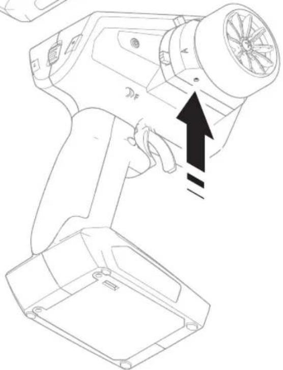
natural_image
Line drawing of a handheld device with a black arrow pointing to the component (no text or symbols present)DATENANSCHLUSS
WAS IST HEADING HOLD?
Additional optional parts and details are available at SpektrumRC.com
GARANTIE UND SERVICE INFORMATIONEN
Garantiezeitraum
22885 Barsbüttel Germany
WEEE-HINWEIS:

http://www.horizonhobby.com/content/support-render-compliance.
Reverse (Inversion)......46
Speed (Vitesse)......46
INSTALLATION DES PILES
MODEL NAME (NOM DE LA MAQUETTE)
MENU
CHANNEL COUNT (NOMBRE DE CANAUX)
MENU
CHANNEL NAME (NOM DES CANAUX)
ABSOLUTE TRAVEL (COURSE ABSOLUE)
EXPONENTIAL (EXPONENTIEL)
MENU
TIMER (MINUTEUR)
MENU
MIXING (MIXAGE)
2 Servo (deux directions)
CHANNEL ASSIGN (ASSIGNATION DES CANAUX)
MENU
TELEMETRY (TÉLÉMÉTRIE)
SETTINGS (PARAMÈTRES)
MENU
Trims
About (à propos)
natural_image
Technical line drawing of a mechanical component with arrows indicating assembly or adjustment points (no text or symbols present)

UTILITIES
MODEL UTILITIES (FONCTIONS UTILITAIRES DE LA MAQUETTE) - SUITE
AJUSTEMENTS PHYSIQUES DE L'ÉMETTEUR
CONVERSION DU VOLANT STANDARD
natural_image
Technical line drawing of a mechanical device with a close-up view of its internal components (no text or symbols)RÉGLAGE DE LA TENSION DE DIRECTION
natural_image
Line drawing of a handheld electric shaver with a hand adjusting its grip (no text or symbols)PORT DE DONNÉES
natural_image
Technical line drawing of a mechanical device with a close-up view of its internal components (no text or symbols)AJUSTEMENT DE L'AVC
22885 Barsbüttel Germany
DIRECTIVE DEEE:

AVC Troubleshooting Guide....76
NOME DEL MODELLO
MENU
CONTEGGIO CANALI
MENU
NOME CANALE
ESPONENZIALE
MENU
TIMER
MENU
MISCELAZIONI
ASSEGNAZIONE CANALE
MENU
TELEMETRIA
Info

SERVIZI
SERVIZI PER IL MODELLO (SEGUE)
Crea nuovo modello
Reset Modello
natural_image
Technical line drawing of a handheld device with a close-up view of its internal components (no text or symbols)natural_image
Technical line drawing of a mechanical component with a hand operating a tool (no text or symbols present)PORTA DATI
natural_image
Technical line drawing of a handheld device with mounting base and control panel (no text or symbols)REGOLAZIONE AVC
AVC TROUBLESHOOTING GUIDE
PROBLEMA POSSIBILE CAUSA SOLUZIONE
22885 Barsbüttel Germany
AVVISO RAEE:

Innovative Spread Spectrum Technology
SMART®
TECHNOLOGY

HORIZON®
H ⊙ B B Y
1121849
© 2025 Horizon Hobby, LLC.
DSMR, DSMS, SLT, AVC and Active Vehicle Control are trademarks or registered trademarks of Horizon Hobby, LLC.
The Spektrum trademark is used with permission of Bachmann Industries, Inc.
All other trademarks, service marks and logos are property of their respective owners.
US 9,320,977. US 10,528,060. US 9,930,567. US 10,419,970. US 10,849,013. Other patents pending.

- MEANING OF SPECIAL LANGUAGE
- WARNING AGAINST COUNTERFEIT PRODUCTS
- WARRANTY REGISTRATION
- SAFETY PRECAUTIONS
- TABLE OF CONTENTS
- BOX CONTENTS
- SPECIFICATIONS
- GETTING STARTED DAILY DRIVING
- Without AVC
- DXC+ CONTROLS AND SWITCHES
- INSTALLING BATTERIES
- MAIN SCREEN
- NAVIGATION
- USING THE SCROLL WHEEL SELECTOR
- INDIVIDUAL DIRECTION ADJUSTMENTS
- AUTO SWITCH SELECT
- SWITCH SELECTION TIP
- CHANNEL MONITOR
- MENU
- MODEL SELECT
- VEHICLE TYPE
- To add select the Vehicle Type:
- MODEL NAME
- To add letters to a Model Name:
- To erase a character(s):
- CHANNEL COUNT
- TRAVEL
- To adjust Travel values:
- SUB-TRIM
- REVERSE
- To reverse a channel direction:
- SPEED
- To adjust the Speed:
- CHANNEL NAME
- To change the Channel Name:
- ABSOLUTE TRAVEL
- RATES
- To adjust Rate values:
- EXPONENTIAL
- To adjust Expo values:
- TIMER
- BIND/FRAME MENU
- Failsafe
- Binding
- Bind Process
- MIXING
- STEERING MIX
- 4WS (4-Wheel Steering)
- Servo (Dual Steering)
- PROGRAMMABLE MIX
- AVC PROGRAMMING MENU
- To activate the AVC menu:
- TRIM SETUP
- To adjust the trim steps:
- TRIM ASSIGN
- CHANNEL ASSIGN
- Channel assign:
- TELEMETRY
- To edit telemetry sensors:
- SMART Throttle\*:
- To view SMART Telemetry:
- To activate Speed information using SMART Telemetry:
- USB SETTINGS
- SETTINGS
- Display
- Contrast
- Duration
- Brightness
- User Name
- Language:
- Inactive Alarm:
- SYSTEM SETTINGS (CONTINUED)
- Sound settings
- About
- CALIBRATE
- SYSTEM SETUP
- MODEL UTILITIES
- UTILITIES
- MODEL UTILITIES (CONTINUED)
- Create New Model
- Delete Model
- Model copy
- Reset Model
- Sort Model List
- PHYSICAL TRANSMITTER ADJUSTMENTS
- STANDARD WHEEL CONVERSION
- STEERING TENSION ADJUSTMENT
- DATA PORT
- AVC TUNING (AVC RECEIVER NOT INCLUDED)
- WHAT IS GAIN?
- WHAT IS PRIORITY?
- WHAT IS HEADING HOLD?
- AVC TUNING PROCEDURE
- GENERAL TUNING TIPS
- CHANGING BATTERY VOLTAGE
- TROUBLESHOOTING GUIDE
- AVC TROUBLESHOOTING GUIDE
- OPTIONAL PARTS LIST
- PART # PARTS DESCRIPTION
- 1-YEAR LIMITED WARRANTY
- What this Warranty Covers
- What is Not Covered
- Purchaser's Remedy
- Limitation of Liability
- Law
- WARRANTY SERVICES
- Questions, Assistance, and Services
- Inspection or Services
- NOTICE: Do not ship LiPo batteries to Horizon. If you have any issue with a LiPo battery, please contact the appropriate Horizon Product Support office.
- Warranty Requirements
- Non-Warranty Service
- WARRANTY AND SERVICE CONTACT INFORMATION
- FCC INFORMATION
- SPMR6130 Transmitter only: Contains FCC ID: BRWPLAN01T
- Supplier's Declaration of Conformity
- IC INFORMATION
- COMPLIANCE INFORMATION FOR THE EUROPEAN UNION
- WEEE NOTICE:
- HINWEIS
- EINSETZEN DER BATTERIEN
- HAUPTBILDSCHIRM
- MODELLNAME
- KANALZUORDNUNG
- TELEMETRIE
- Über
- MODELLAUSWAHL
- DIENSTPROGRAMME
- MODELL-DIENSTPROGRAMME (FORTSETZUNG)
- Modelle löschen
- Modellkopie
- DATENANSCHLUSS
- WAS IST HEADING HOLD?
- GARANTIE UND SERVICE INFORMATIONEN
- Garantiezeitraum
- WEEE-HINWEIS:
- INSTALLATION DES PILES
- MODEL NAME (NOM DE LA MAQUETTE)
- CHANNEL COUNT (NOMBRE DE CANAUX)
- CHANNEL NAME (NOM DES CANAUX)
- ABSOLUTE TRAVEL (COURSE ABSOLUE)
- EXPONENTIAL (EXPONENTIEL)
- TIMER (MINUTEUR)
- MIXING (MIXAGE)
- Servo (deux directions)
- CHANNEL ASSIGN (ASSIGNATION DES CANAUX)
- TELEMETRY (TÉLÉMÉTRIE)
- SETTINGS (PARAMÈTRES)
- Trims
- About (à propos)
- MODEL UTILITIES (FONCTIONS UTILITAIRES DE LA MAQUETTE) - SUITE
- AJUSTEMENTS PHYSIQUES DE L'ÉMETTEUR
- CONVERSION DU VOLANT STANDARD
- RÉGLAGE DE LA TENSION DE DIRECTION
- PORT DE DONNÉES
- AJUSTEMENT DE L'AVC
- NOME DEL MODELLO
- CONTEGGIO CANALI
- NOME CANALE
- ESPONENZIALE
- MISCELAZIONI
- ASSEGNAZIONE CANALE
- TELEMETRIA
- Info
- SERVIZI
- SERVIZI PER IL MODELLO (SEGUE)
- Crea nuovo modello
- Reset Modello
- PORTA DATI
- REGOLAZIONE AVC
- AVVISO RAEE:
Brand : SPEKTRUM
Model : DXC+
Category : Remote control toy