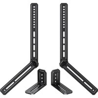
ERSB1-01B - Speaker stands ErgoAV - Free user manual and instructions
Find the device manual for free ERSB1-01B ErgoAV in PDF.


| Product Type | Speaker mount (soundbar) for rear TV attachment |
| Brand | ErgoAV |
| Model | ERSB1-01B |
| Maximum Load Capacity | 15 lb (6.8 kg) |
| Main Material | Steel |
| Color | Black (common) |
| Mounting Compatibility | M4, M5, M6 and M8 screws; keyhole slots; threaded holes on back or bottom |
| Rotation Angle | 360° (adjustable by knob) |
| Height Adjustment | Yes, by tightening knob |
| Wall Mount Required | TV wall mount not included, must support 5 times total weight |
| Number of Brackets Included | 2 (one pair) |
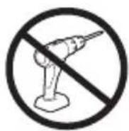
| Tools Required | Screwdriver (not included) |
| Included Parts | Adjustable brackets, screws, washers, spacers of various sizes |
| Maintenance | Clean with a dry, soft cloth. Do not use abrasive products. |
| Safety | Do not exceed weight capacity. Check wall mount solidity. Use only as described. |
| Warranty | Contact customer service (support@ergoav.com) |
| Repairability | Spare parts available on request from manufacturer |
| Recommended Installation | By a professional if necessary. Read manual carefully. |
| Intended Use | Attach a soundbar to the back of a compatible TV (flat or curved) |
| Country of Origin | Not specified |
Frequently Asked Questions - ERSB1-01B ErgoAV
User questions about ERSB1-01B ErgoAV
0 question about this device. Answer the ones you know or ask your own.
Ask a new question about this device
Download the instructions for your Speaker stands in PDF format for free! Find your manual ERSB1-01B - ErgoAV and take your electronic device back in hand. On this page are published all the documents necessary for the use of your device. ERSB1-01B by ErgoAV.
USER MANUAL ERSB1-01B ErgoAV
Universal Soundbar Mount Instruction Manual
Rev00
ERSB1
English: 03-26
Français : 27 à 50
Español: 51 a 74
Thank you for choosing ErgoAV!
At ErgoAV, our goal is to add value to your AV experience by providing the highest quality products and services in the industry. We offer a 5-year warranty. If you have any questions or concerns, please contact us.
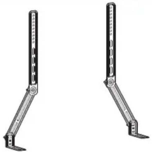
natural_image
Two identical mechanical lever arms with mounting feet, shown from different angles (no text or symbols)
ErgoAV

9501 Louisiana Ave N, #200, Brooklyn Park, MN 55445

(877) 419-7832
Mon-Fri 8am - 8pm (CST)

support@ergoav.com www.ergoav.com
IMPORTANT SAFETY INFORMATION
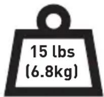
Weight Capacity Do not exceed weight capacity.
- Check package contents against supplied parts and hardware list to ensure that all parts were received and undamaged. DO NOT use damaged or defective parts. If you require replacement parts, please call technical support or email customer service.
- Carefully read all instructions before attempting installation. If you DO NOT understand the instructions or if you have any questions or concerns, please call technical support or email customer service.
- DO NOT use this product for any purpose that is not explicitly specified in this manual. DO NOT exceed weight capacity. We are not liable for damage or injury caused by improper mounting, incorrect assembly or inappropriate use.
- This speaker mount is only designed to be installed on the back of a compatible TV.
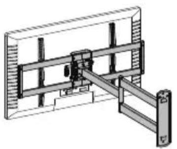
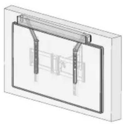
WARNING: When attaching to a TV wall mount, the wall must be capable of supporting five times the weight of your TV, TV mount, and soundbar combined.
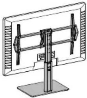
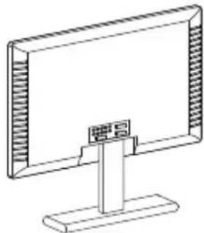
TV Mount TV Monitor TV Stand
natural_image
Technical line drawing of a mechanical assembly with no visible text or symbols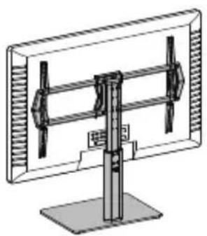
natural_image
Technical line drawing of a monitor with dual vertical supports and a base stand (no text or symbols)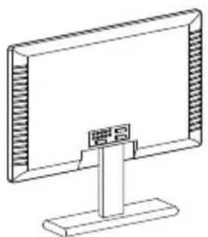
natural_image
Line drawing of a flat-screen computer monitor with a stand (no text or symbols)
When attaching to a TV mount, TV stand or TV monitor, check the weight capacity of your TV mount, TV stand and/or whether the original TV legs can support the extra weight.
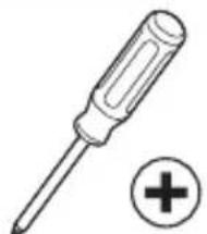
Tools Needed (Not Included)
natural_image
Illustration of a screwdriver with a plus button symbol (no text or labels)Phillips Screwdriver
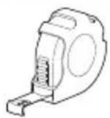
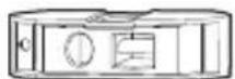
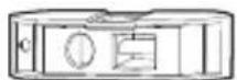
LevelTape Measure
05
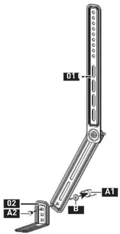
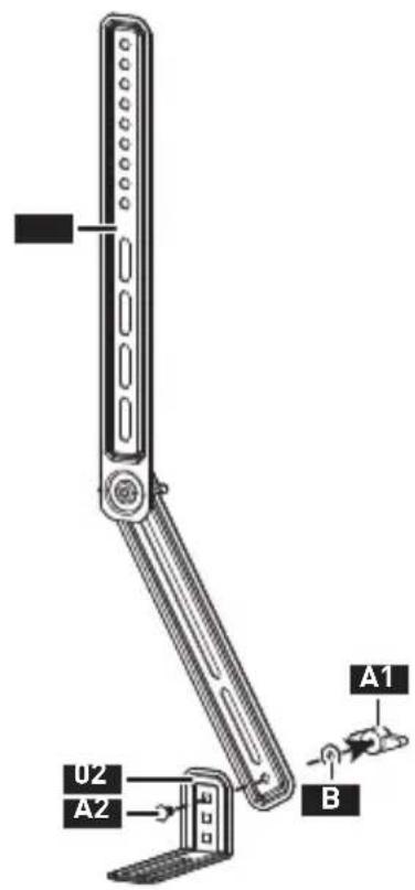
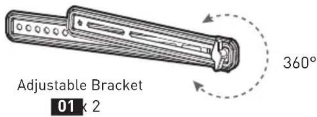
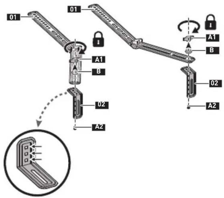
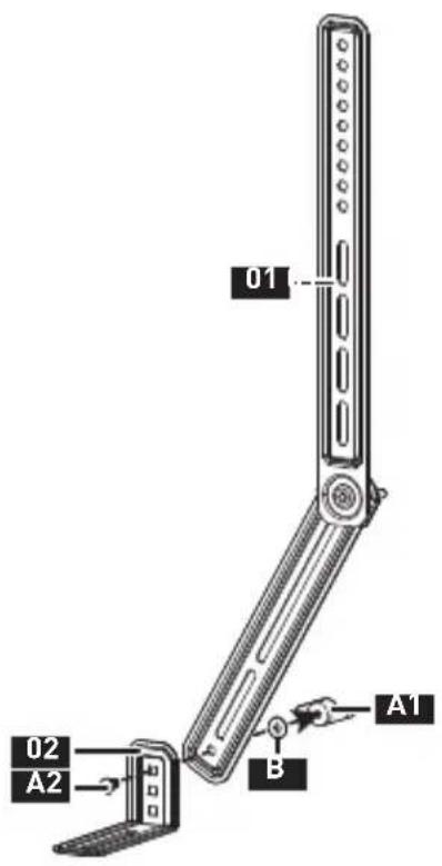
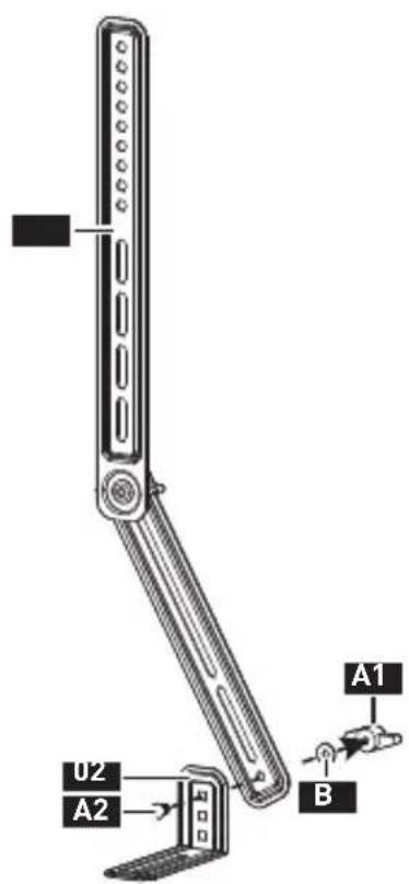
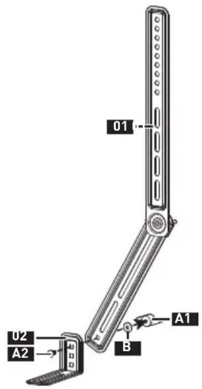
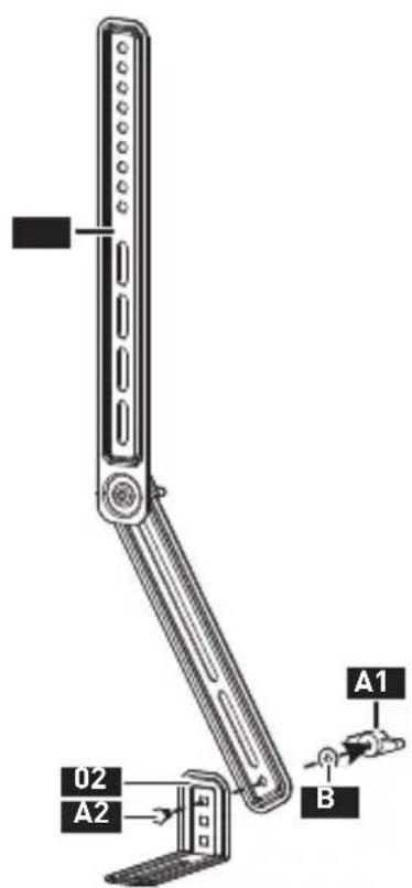
01 Adjustable Bracket
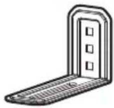
02 Speaker Bracket
A1 Knob
A2 Bolt
B Washer
Supplied Parts and Hardware for Step 1
INSTALLATION
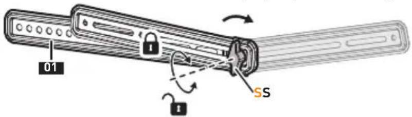
STEP 1 Infold the Adjustable Bracket
Slightly loosen the knob [S] and unfold the bracket to the proper position. Retighten the knob to lock it.
Supplied Parts and Hardware for Step 2
Not all hardware included in this package will be used.
natural_image
Simple line drawing of a door frame with no text or symbolsSpeaker Bracket
02×2
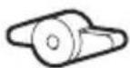
Knob
A1 k 2
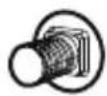
M6 x 12mm
Bolt
A2×2

D6 Washer
B 4
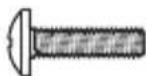
M4 x 16mm
Bolt
C x 2
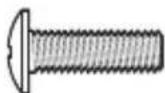
M5 x 16mm
Bolt
D × 2
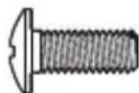
M6 x 16mm
Bolt
E x 2
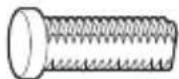
Key Hole
Bolt
F x 2
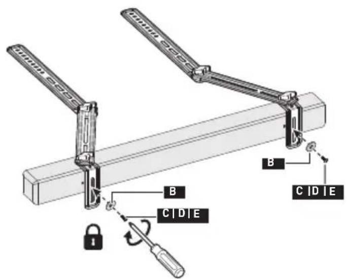
STEP 2 Attach the Soundbar
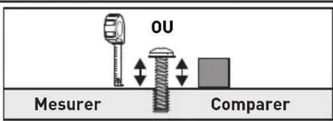
2-1 Measure the distance between the mounting holes for easier installation of the adjustable brackets.
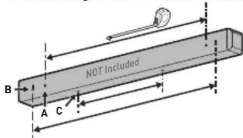
Option A Option B Option C
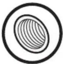
Speaker with Threaded Holes on Back
natural_image
Simple line drawing of an oval shape enclosed in a circle (no text or symbols)
Page 11
C
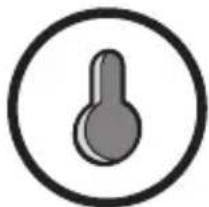
Speaker with Keyhole Slots
natural_image
Simple icon of a thermometer inside a circle (no text or symbols)
Page 12
Speaker with Threaded Holes on Bottom

natural_image
Simple line drawing of an oval with concentric rings, no text or symbols present
Page 13
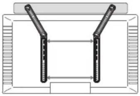
2-2 Choose the proper bracket configuration according to your measurements and TV mount type.
For TV Wall Mount:
natural_image
Diagram of a double-tube electrical connector or switch assembly inside a rectangular frame (no text or symbols)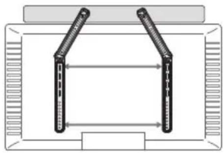
natural_image
Diagram of two vertical connectors mounted on a rectangular frame with directional arrows indicating alignment (no text or symbols)
natural_image
Diagram of a symmetrical mechanical or structural assembly with two arms and dimension lines, no text or symbols present.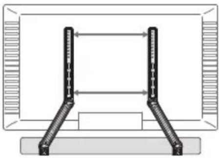
natural_image
Diagram of a computer monitor with two vertical connectors and bidirectional arrows indicating alignment (no text or symbols)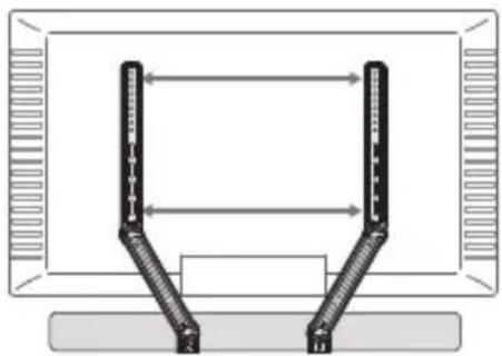
natural_image
Diagram of a U-shaped device with bidirectional arrows indicating alignment or connection between two panels (no text or symbols)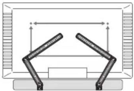
natural_image
Diagram of a mechanical assembly with two arms and directional arrows, no text or symbols presentFor TV Back or Tabletop TV Stand:
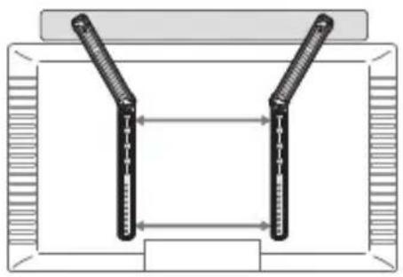
natural_image
Pure diagram of two vertical connectors inside a rectangular frame, no text or symbols present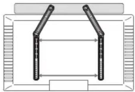
natural_image
Diagram of a U-shaped structure with two vertical supports and bidirectional arrows indicating measurement or alignment (no text or symbols)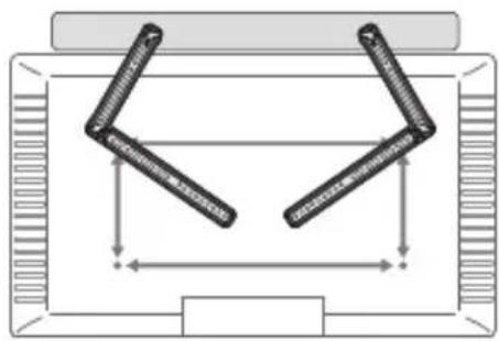
natural_image
Diagram of a mechanical or structural assembly with two symmetrical arms and dimension lines (no text or symbols)
Option A Speaker with Threaded Holes on Back
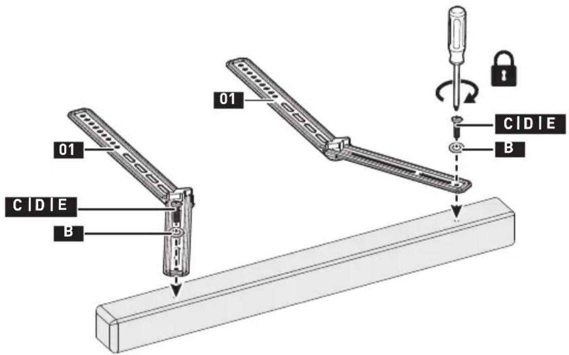
Option B Speaker with Keyhole Slots
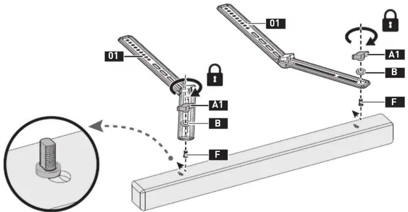
12
Option C Speaker with Threaded Holes on Bottom
Supplied Parts and Hardware for Step 3
Not all hardware included in this package will be used.
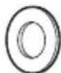
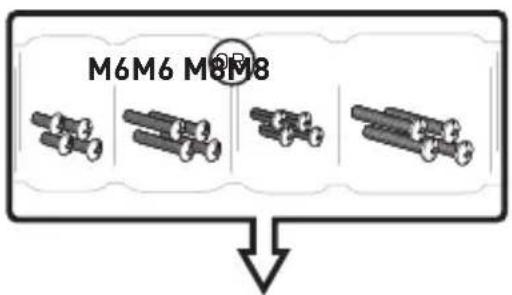
M6/M8
Washer
M-A×4
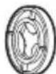
L2.5mm
Spacer
M-B1×4
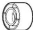
L10mm
Spacer
M-B2×4
M6 M8
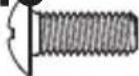
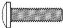
M6 x 15mm
TV Bolt
M-C1×4 M-D1×MMED2×4
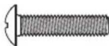
M6 x 25mm
TV Bolt
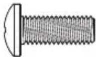
M8 x 20mm
TV Bolt

M8 x 30mm
TV Bolt

STEP 3 Attach the Soundbar to TV
3-1 Prepare your TV [If mounted]

![ErgoAV ERSB1-01B - 3-1 Prepare your TV [If mounted] - 2](/content/2026/05/755926/images/eb1681f0eeccb3740f68c80bd01378f5e16105fabcb1b07c8bf2afe27cb265cf.jpg)
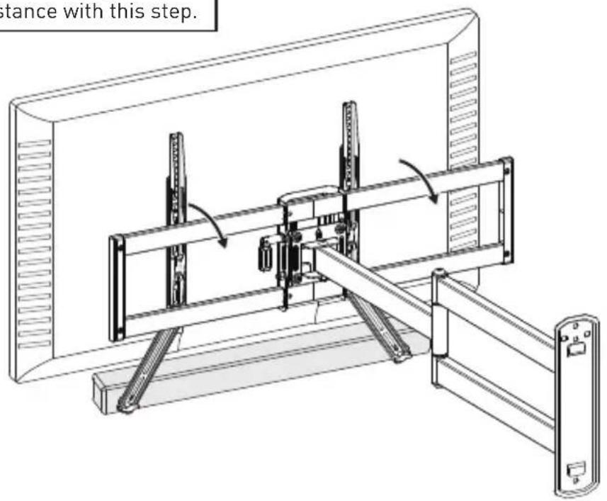
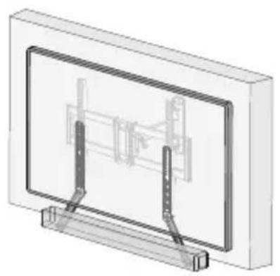
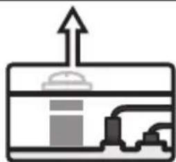
NOTE: Follow your TV wall mount's manual to properly remove your TV. Your TV wall mount may vary from the illustrations below, but the steps for soundbar installation should remain the same.
![ErgoAV ERSB1-01B - 3-1 Prepare your TV [If mounted] - 3](/content/2026/05/755926/images/db84140a6d2eb95484297a186f3c9fed2683a12a5af81473233f48bdb5f72173.jpg)
natural_image
Technical diagram of a mechanical assembly with pipes and components, no visible text or symbols![ErgoAV ERSB1-01B - 3-1 Prepare your TV [If mounted] - 4](/content/2026/05/755926/images/14af6f208b7271cf8f49b987a8219272b87e8e8eb60ead1144af198aa5fd59ed.jpg)
natural_image
Technical diagram of a mechanical assembly with no visible text or symbols![ErgoAV ERSB1-01B - 3-1 Prepare your TV [If mounted] - 5](/content/2026/05/755926/images/afa6566bc1276e40df946fb938220a2e4989a690c9b6820cbe1213b0dfced63b.jpg)
natural_image
Diagram of two mechanical components with upward force arrow, no text or symbols present![ErgoAV ERSB1-01B - 3-1 Prepare your TV [If mounted] - 6](/content/2026/05/755926/images/ef748b0d3b0b5a1115975c292dc527e1c71c66e7bc3d87b885950d212268b1c7.jpg)
HEAVY! You may need assistance with this step.
3-2 Select TV Bolts
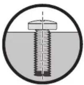
The correct bolt diameter will thread smoothly into your TV.
natural_image
Cross-sectional diagram of a bolt with threaded shaft and cap, enclosed in a circle (no text or symbols)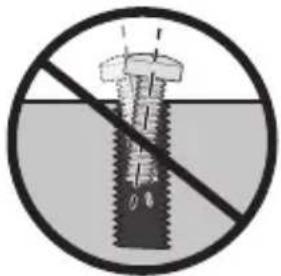

The depth of the top and bottom holes may differ.
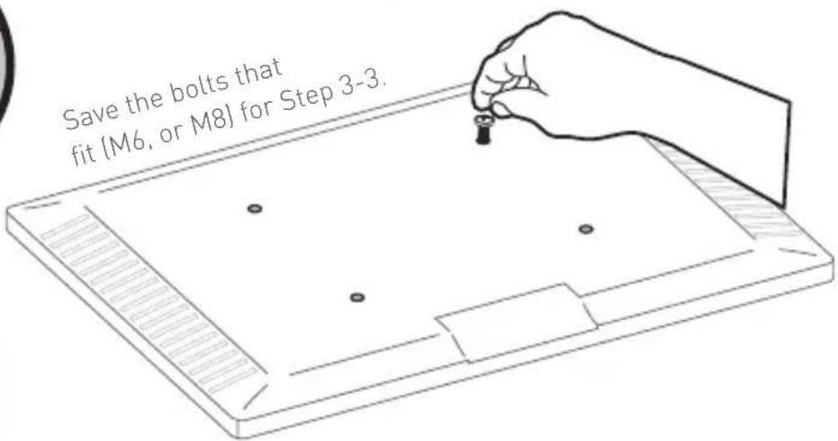
3-3 Secure the TV Brackets and Soundbar Brackets
For Flat-Back TV, go to Option A on page 19.
For Bump, Curved TV, Recessed Holes and Cables, go to Option B on page 20-21.

WARNING:
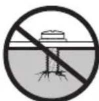
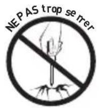
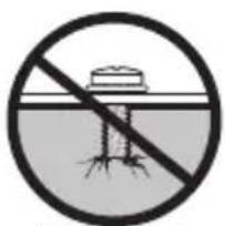
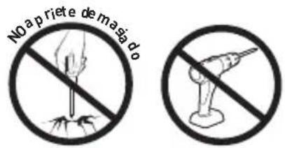
- DO NOT turn the bolt past the bottom of the hole.
- If the bolt is too short, it may not adequately support the TV.
- If the bolt is too long, it could damage the TV.
- At least 4–5 turns into the threading is required.
- The depth of the bottom holes may be different from the top holes.
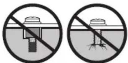
natural_image
Two circular icons showing a dam or structure with a diagonal line crossing it, no text or symbols present.Too Short Too Long
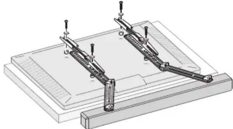
natural_image
Technical illustration of a mechanical assembly with two parallel clamps mounted on a base plate (no text or symbols)17

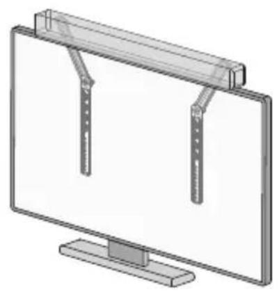
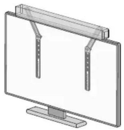
NOTE: The soundbar should be installed above the TV when used with a tabletop TV stand or TV monitor.
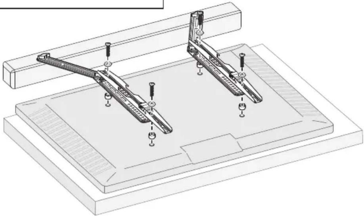
natural_image
Technical line drawing of a mechanical assembly with two articulated arms and mounting base (no text or symbols)Option A
Use short TV bolts with washers.

Flat-Back TV

natural_image
Pure diagram of a mechanical device without any text, numbers, or symbols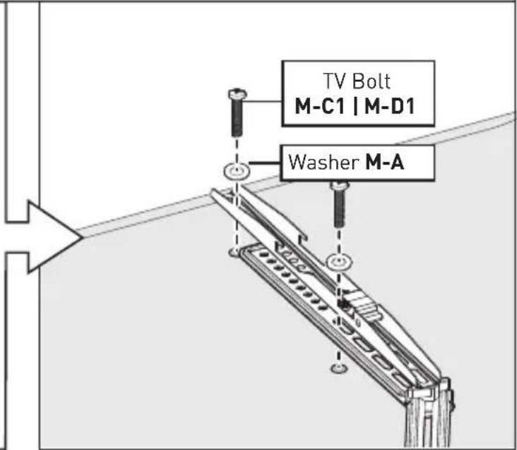
Option B
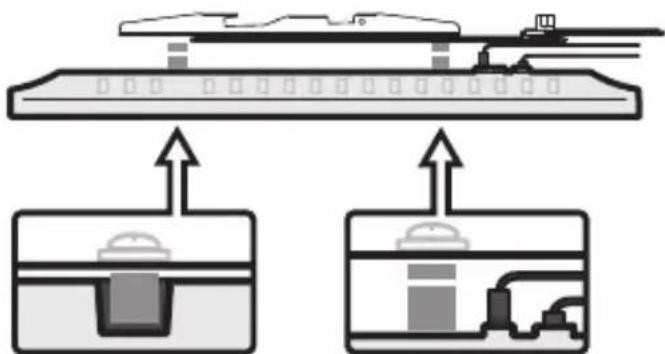
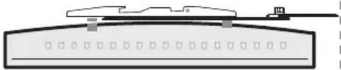
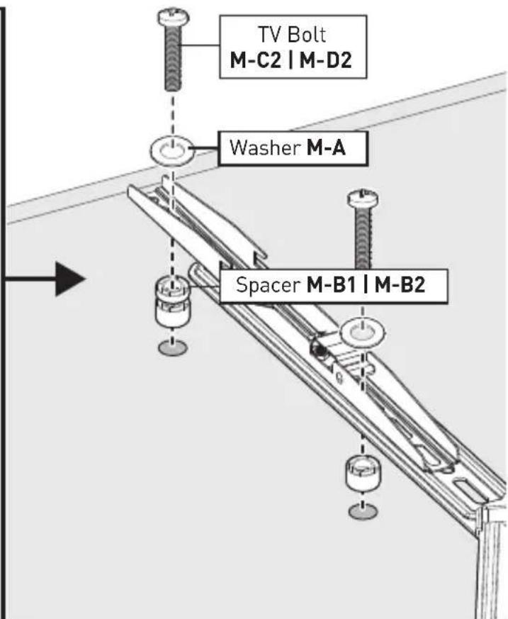
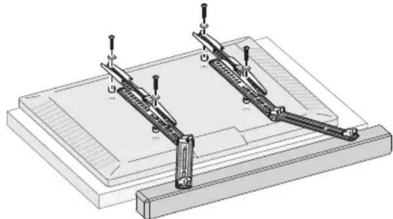
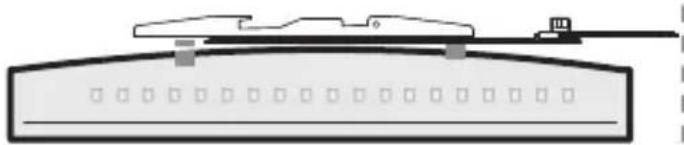
Use long TV bolts with washers and spacers to create extra space between the TV and brackets.


Bump

natural_image
Pure technical diagram of a mechanical device without any text, numbers, or symbolsTV with Mounting Restrictions
Curved TV
natural_image
Pure technical diagram of a mechanical component or assembly without any text, numbers, or symbolsRecessed Holes Protruding Cables
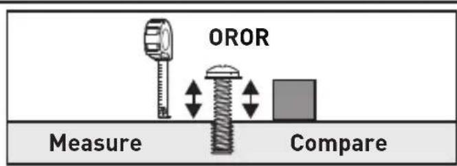
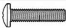
You can use a tape measure to measure the protruding bolts or hold spacers next to them to choose the right spacer combination.
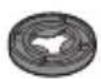
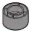
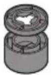
Note:
There are many possible spacer combinations that can be used.


(877) 419-7832

support@ergoav.com
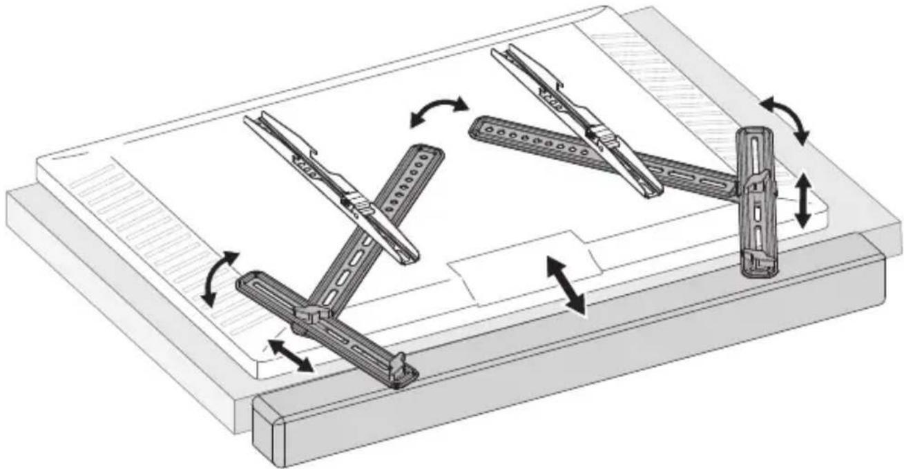
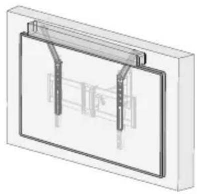
3-4 If needed, adjust the soundbar brackets to the desired position before hanging.
natural_image
Technical diagram of a mechanical assembly with multiple arms and levers, showing rotational motion arrows (no text or symbols)3-5

HEAVY! You may need assistance with this step.
natural_image
3D diagram of a wall-mounted device with two vertical supports and a central panel (no text or symbols)OR

natural_image
3D diagram of a rectangular frame with vertical supports and internal structural elements, no text or symbols presentOR
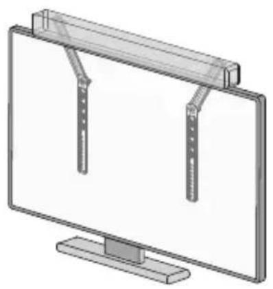
natural_image
Illustration of a flat-screen monitor with two vertical connectors on top (no text or symbols)STEP 4 adjust the Soundbar Brackets
Slightly loosen the knobs [S], then adjust the bracket to the desired position. Retighten the knobs to lock it.
![the knobs to lock it. Note: Please DO NOT overtighten or overloosen the knobs [S]. SS](/content/2026/05/755926/images/94c4a4e01a597114bd3f1afa7e456f4d3a5e41e7a347b97cec0b803140ad13ad.jpg)
TIP: You can adjust the soundbar to make it closer to the bottom of the TV.
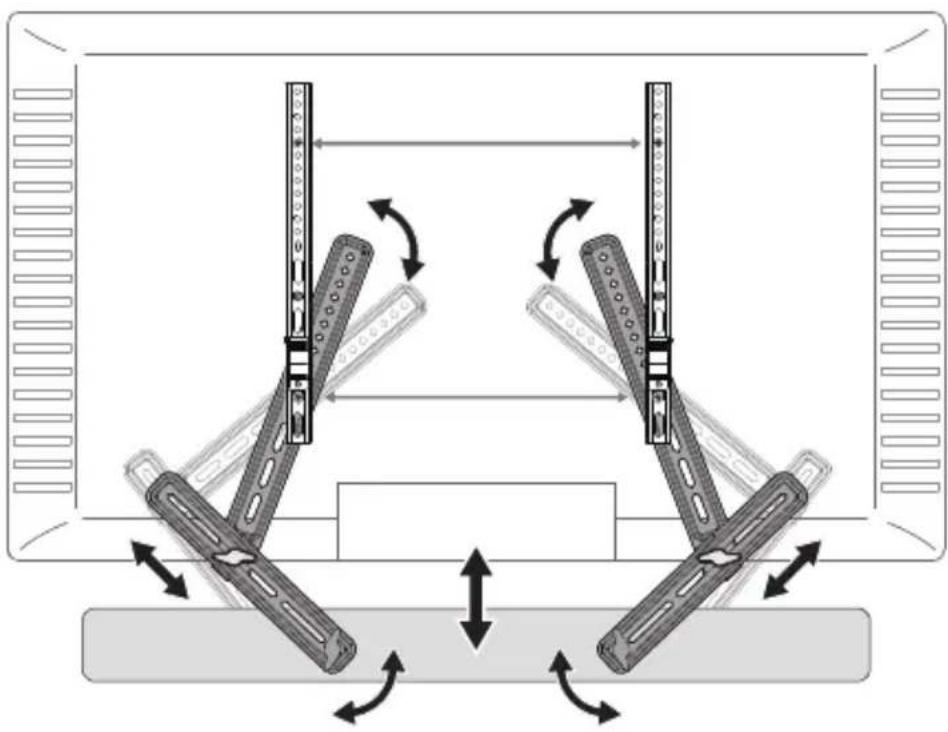
natural_image
Diagram of a mechanical linkage system with bidirectional arrows indicating movement, no text or symbols presentINFORMATIONS DE SÉCURITÉ IMPORTANTES
natural_image
Technical line drawing of a mechanical assembly with no visible text or symbolsSupport TV

natural_image
Technical line drawing of a computer monitor with dual-mounted fans and a stand (no text or symbols)Moniteur TV
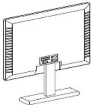
natural_image
Line drawing of a flat-screen monitor with a stand (no text or symbols)
natural_image
Illustration of a screwdriver with a plus sign symbol (no text or labels)Tournevis Phillips
NiveauMètre à ruban
29
natural_image
Simple line drawing of a door or shelf with no text or symbolsnatural_image
Simple line drawing of an oval with concentric circles, no text or symbols present
Page 35
Option B
natural_image
Simple line drawing of a circular shape with concentric ovals and internal horizontal lines (no text or symbols)
Page 37
natural_image
Diagram of a mechanical or electrical component with two vertical arms and a central horizontal bar, enclosed in a rectangular frame (no text or symbols)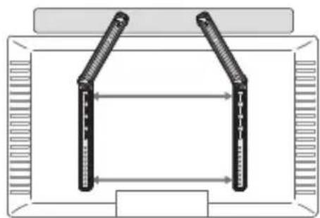
natural_image
Diagram of two vertical connectors mounted on a rectangular frame, with bidirectional arrows indicating alignment or connection (no text or symbols)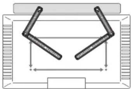
natural_image
Diagram of a mechanical or structural assembly with two symmetrical arms and dimension arrows, no text or symbols present.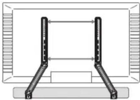
natural_image
Diagram of a dual-panel computer monitor with two connectors and a central screen (no text or symbols)
natural_image
Diagram of a U-shaped mechanical or electrical component with bidirectional arrows indicating alignment, enclosed in a rectangular frame (no text or symbols)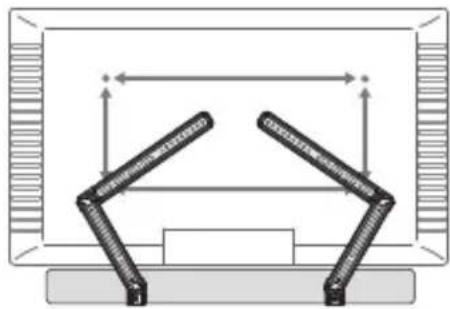
natural_image
Diagram of a mechanical linkage system with two articulated arms and directional arrows, enclosed in a rectangular frame (no text or symbols)natural_image
Diagram of two vertical connectors connected in a Y-shaped layout within a rectangular frame (no text or symbols)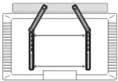
natural_image
Diagram of two vertical connectors mounted on a rectangular frame, with no text or symbols present.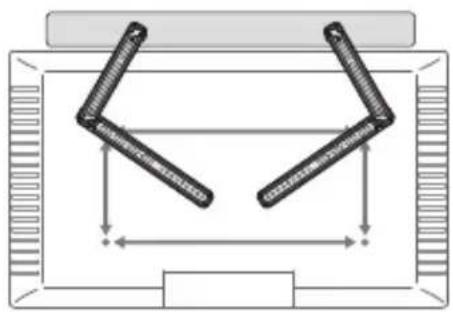
natural_image
Diagram of a mechanical or structural assembly with two symmetrical arms and dimension arrows, no text or symbols present.
The image contains a single, solid horizontal line, which is a stylistic or background element (like a rule line on paper). According to Rule 2, such lines must be ignored by the OCR result. Therefore, the corrected OCR text is:
[Empty]
M6
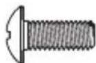
M6 x 15mm

natural_image
Technical diagram of a mechanical assembly with no visible text or symbols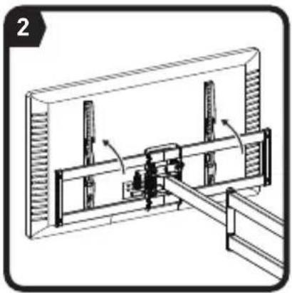
natural_image
Technical diagram of a mechanical assembly with no visible text or symbols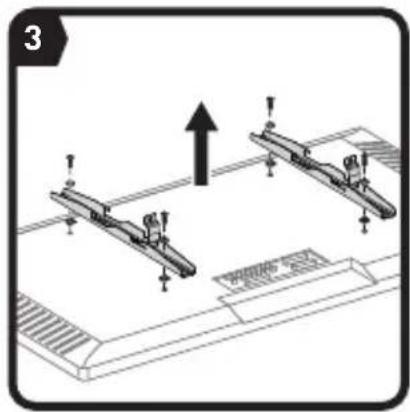
natural_image
Technical diagram showing two mechanical components with an upward arrow, no text or symbols present
natural_image
Cross-sectional diagram of a bolt with threaded shaft and cap, enclosed in a circle (no text or labels)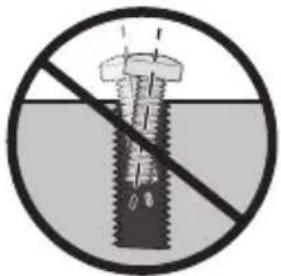

Trop court
natural_image
Prohibition sign showing a water level with a prohibition symbol (no text or numbers present)Trop long
natural_image
Technical illustration of a mechanical clamp or bracket assembly mounted on a base plate (no text or symbols visible)41

natural_image
Pure technical diagram of a mechanical assembly without any text, numbers, or symbols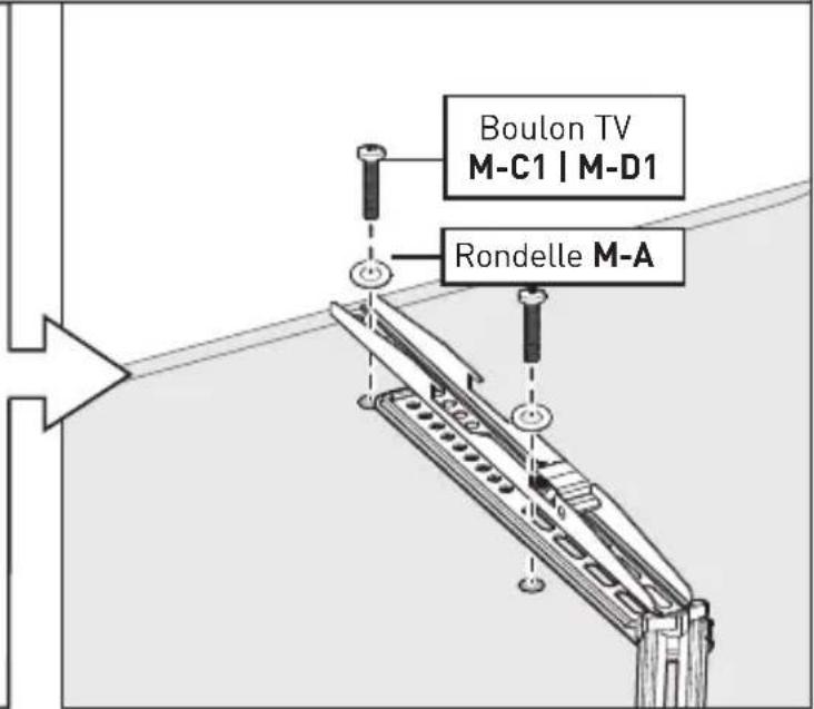
Option B
natural_image
Pure technical diagram of a mechanical device without any text, numbers, or symbolsTV courbe
natural_image
Pure diagram of a mechanical or architectural component with no text, numbers, or symbolsTrous encastrés
natural_image
Diagram of a mechanical or fluid system with an upward arrow and internal components (no text or symbols)Câbles saillants
natural_image
Technical diagram of a mechanical assembly with multiple arms and levers, showing rotational motion arrows (no text or symbols)3-5

natural_image
3D diagram of a rectangular wall-mounted device with two vertical supports and a central internal structure (no text or symbols)OU
natural_image
3D diagram of a rectangular frame with vertical supports and internal structural elements (no text or symbols)OU
natural_image
Illustration of a flat-screen monitor with two vertical connectors on top (no text or symbols)natural_image
Diagram of a mechanical linkage system with bidirectional arrows indicating movement, no text or symbols presentnatural_image
Technical line drawing of a mechanical assembly with no visible text or symbolsSoporte para TV
natural_image
Technical line drawing of a monitor with dual vertical fans and a stand (no text or symbols)Monitor de TV
natural_image
Line drawing of a flat-screen monitor with a stand and top panel (no text or symbols)
natural_image
Illustration of a screwdriver with a plus sign symbol (no text or labels)Destornillador Phillips
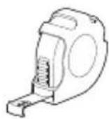
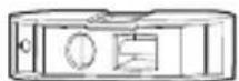
NivelCinta Métrica
53
01 Soporte Ajustable
02 Soporte para Altavoz
A1 Perilla
A2 Tornillo
B Arandela
natural_image
Simple line drawing of a door hinge with no text or symbolsnatural_image
Simple line drawing of an oval with internal parallel lines, enclosed in a larger circle (no text or symbols)
Página 59
Opción B
natural_image
Simple line drawing of an oval with concentric rings, no text or symbols present
Página 61
natural_image
Diagram of a symmetrical mechanical or electrical component with two vertical arms and bidirectional arrows indicating alignment (no text or symbols)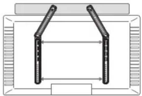
natural_image
Diagram of a mechanical or electrical setup with two vertical supports and bidirectional arrows indicating movement (no text or symbols)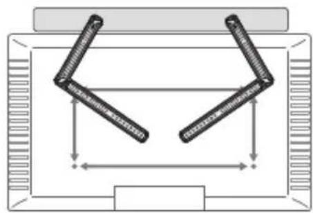
natural_image
Diagram of a mechanical linkage system with two arms and dimension arrows (no text or labels)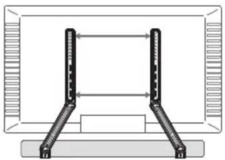
natural_image
Diagram of a mechanical or structural assembly with two vertical supports and a central horizontal bar (no text or symbols)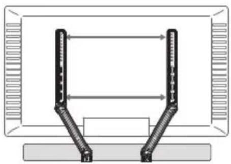
natural_image
Diagram of a mechanical or electrical component with two vertical arms and directional arrows, no text or symbols present.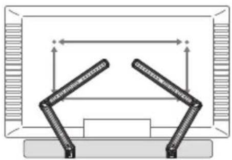
natural_image
Diagram of a mechanical assembly with two articulated arms and directional arrows, no text or symbols presentnatural_image
Diagram of a mechanical or electrical component with two vertical arms and a central horizontal bar, enclosed in a rectangular frame (no text or symbols)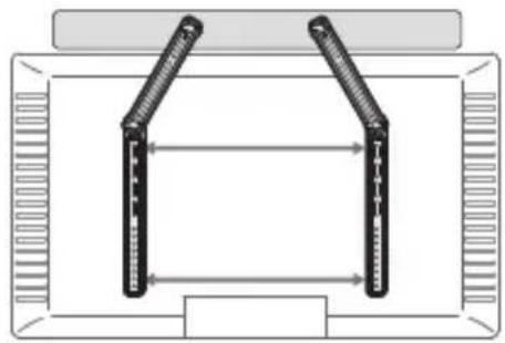
natural_image
Diagram of two vertical connectors mounted on a rectangular frame with directional arrows indicating movement or force (no text or symbols)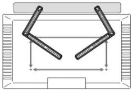
natural_image
Diagram of a mechanical linkage system with two arms and dimension arrows (no text or labels)
The image contains no text or characters. It is a blank rectangular box with no visible content, figures, or markings.
M6
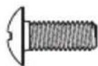
M6 x 15mm
Tornillo para TV
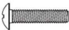
M6 x 25mm
Tornillo para TV
M-C1×4 M-D1×4 M-C2×4
M8
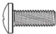
M8 x 20mm
Tornillo para TV
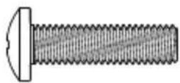
M8 x 30mm
Tornillo para TV
M-D2×4
natural_image
Technical diagram of a mechanical assembly with no visible text or symbols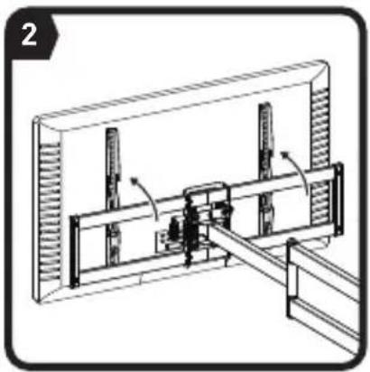
natural_image
Technical diagram of a mechanical assembly with no visible text or symbols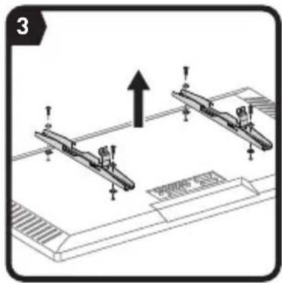
natural_image
Diagram of mechanical assembly with two vertical supports and an upward arrow, no text or symbols present
natural_image
Cross-sectional diagram of a bolt with concentric circles and centerline, no text or symbols present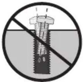

natural_image
Prohibition sign with a crossed-out screw and horizontal bar, no text or symbols presentDemasiado Corto
natural_image
Prohibition sign showing a prohibition symbol with a water level and a floating object (no text or numbers present)Demasiado Largo
natural_image
Technical line drawing of a mechanical assembly with two articulated arms and mounting base (no text or symbols)Opción A
natural_image
Pure diagram of a mechanical or electrical component without any text, numbers, or symbols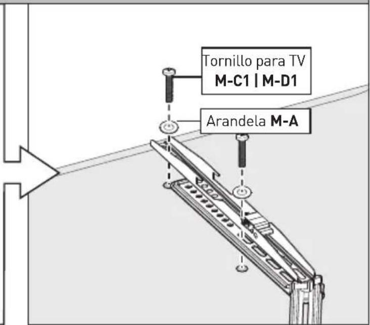
Opción B
natural_image
Pure technical diagram of a mechanical assembly without any text, numbers, or symbolsTV Curvada
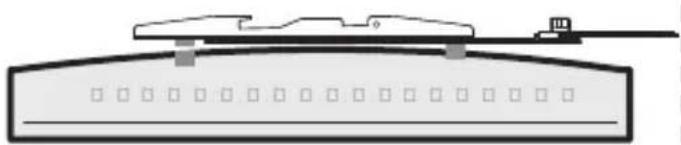
natural_image
Pure diagram of a mechanical or architectural component with no text, numbers, or symbolsnatural_image
Technical diagram of a mechanical assembly with multiple arms and levers, showing rotational motion arrows (no text or symbols)3-5

natural_image
3D diagram of a rectangular panel with vertical supports and internal structural elements (no text or symbols)0
natural_image
3D diagram of a rectangular frame with vertical supports and internal structural elements, no text or symbols present0
natural_image
Illustration of a flat-screen monitor with two vertical supports and a central screen (no text or symbols)natural_image
Diagram of a mechanical linkage system with bidirectional arrows indicating movement, no text or symbols presentERGOAV™
At ErgoAV, our goal is to provide the high-quality audio video solutions and product support that you need. If you have any questions, concerns, or feedback, please let us know!
natural_image
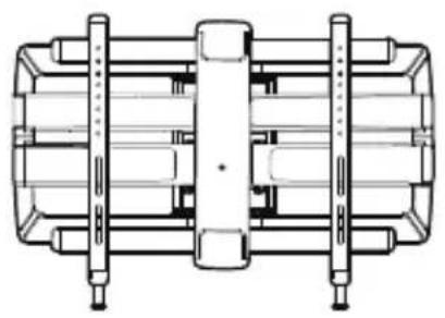
Technical line drawing of a mechanical assembly with no visible text or symbolsTV Mounts
natural_image
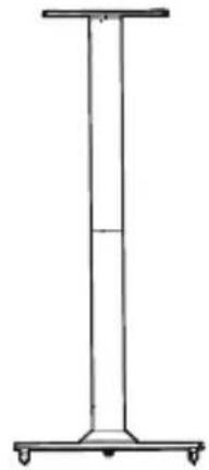
Simple line drawing of a vertical cylindrical structure with four wheels at both ends (no text or symbols)Speaker Stands
natural_image
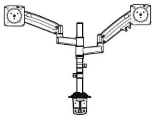
Technical line drawing of a Y-shaped mechanical or electrical component with two arms and a central base (no text or symbols)Computer Monitor Mounts


9501 Louisiana Ave N, #200, Brooklyn Park, MN 55445ErgoAV

(877) 419-7832 Mon-Fri 8am - 8pm (CST) support@ergoav.com www.ergoav.com
860-03126-00 Rev00
- Universal Soundbar Mount Instruction Manual
- ERSB1
- Thank you for choosing ErgoAV!
- IMPORTANT SAFETY INFORMATION
- Weight Capacity Do not exceed weight capacity.
- Tools Needed (Not Included)
- Supplied Parts and Hardware for Step 1
- INSTALLATION
- STEP 1 Infold the Adjustable Bracket
- Supplied Parts and Hardware for Step 2
- STEP 2 Attach the Soundbar
- Option A Option B Option C
- C
- Option A Speaker with Threaded Holes on Back
- Option B Speaker with Keyhole Slots
- Option C Speaker with Threaded Holes on Bottom
- Supplied Parts and Hardware for Step 3
- M6 M8
- STEP 3 Attach the Soundbar to TV
- 3-1 Prepare your TV [If mounted]
- 3-2 Select TV Bolts
- 3-3 Secure the TV Brackets and Soundbar Brackets
- WARNING:
- Option A
- Flat-Back TV
- Option B
- Note:
- 3-5
- STEP 4 adjust the Soundbar Brackets
- INFORMATIONS DE SÉCURITÉ IMPORTANTES
- M6
- Opción B
- Opción A
- ERGOAV™
Brand : ErgoAV
Model : ERSB1-01B
Category : Speaker stands