T304 - Inverter Powersoft - Free user manual and instructions
Find the device manual for free T304 Powersoft in PDF.


| Product type | Professional audio amplifier |
| Model | T304 |
| Brand | Powersoft |
| Power supply | 100-240 V AC ±10%, 16 A max, 10 kA circuit breaker curve C or D |
| Channel configuration | 4 channels (inputs/outputs) |
| Cooling | Variable speed DC fans, front-to-back airflow |
| Input connectors | 4 female XLR (analog), 1 XLR AES3, 2 Ethercon (Dante/AES67) |
| Output connectors | 4 Speakon NL-4 |
| Display | 1.8" color TFT display, RGB backlight |
| Control | 8 RGB backlit push buttons, USB port, ArmoníaPlus software |
| Networking | Dante (non-A models), AES3, analog |
| Operating temperature | 0°C to +35°C (derating above) |
| Ambient humidity | 10% to 85% non-condensing |
| Maximum altitude | 2000 m |
| Usage | Indoor only |
| Maintenance | Clean air filter with compressed air or water, dry cloth for chassis |
| Safety | Mandatory grounding, do not open, disconnect before cleaning, use only by qualified personnel |
| Warranty | Limited warranty, repair by Powersoft authorized center |
| Repairability | No user-serviceable parts |
| Compliance | CE, WEEE, Class A (EMC), RoHS |
Frequently Asked Questions - T304 Powersoft
User questions about T304 Powersoft
0 question about this device. Answer the ones you know or ask your own.
Ask a new question about this device
Download the instructions for your Inverter in PDF format for free! Find your manual T304 - Powersoft and take your electronic device back in hand. On this page are published all the documents necessary for the use of your device. T304 by Powersoft.
USER MANUAL T304 Powersoft
Important Safety Instructions
Common symbols and meanings

THE TRIANGLE WITH THE LIGHTNING BOLT IS USED TO ALERT THE USER TO THE RISK OF ELECTRIC SHOCK.
THE TRIANGLE WITH THE EXCLAMATION POINT IS USED TO ALERT THE USER TO IMPORTANT OPERATING OR MAINTENANCE INSTRUCTIONS.
THE CE-MARK INDICATES THE COMPLIANCE OF THE PRODUCT TO ALL THE APPLICABLE EUROPEAN DIRECTIVES
SYMBOL FOR EARTH/GROUND CONNECTION.
SYMBOL INDICATING THAT THE EQUIPMENT IS FOR INDOOR USE ONLY.
SYMBOL FOR CONFORMITY WITH DIRECTIVE 2012/19/EC OF THE EUROPEAN PARLIAMENT ON WASTE ELECTRICAL AND ELECTRONIC EQUIPMENT (WEEE).
Safety Warnings
OPERATING TEMPERATURE RANGE: 0°C TO +35°C - DERATING ABOVE 35°C.
STORAGE RELATIVE HUMIDITY RANGE: 10% TO 85% HUMIDITY (NON CONDENSING).
DO NOT USE THE UNIT AT ALTITUDES ABOVE 2000 M.
DO NOT USE THE UNIT IN TROPICAL ENVIRONMENT.
TO REDUCE THE RISK OF ELECTRIC SHOCK, DO NOT ATTEMPT TO OPEN ANY PART OF THE UNIT. NO USER-SERVICEABLE PARTS INSIDE. REFER SERVICING TO QUALIFIED SERVICE PERSONNEL.
CONNECTION TO THE MAINS SHALL BE DONE ONLY BY A ELECTROTECHNICAL SKILLED PERSON ACCORDING THE NATIONAL REQUIREMENTS OF THE COUNTRIES WHERE THE UNIT IS SOLD.
DO NOT USE THIS AMPLIFIER IF THE ELECTRICAL POWER CORD IS FRAYED OR BROKEN.
TO AVOID ELECTRICAL SHOCK, DO NOT TOUCH ANY EXPOSED SPEAKER WIRING WHILE THE AMPLIFIER IS OPERATING.
DO NOT SPILL WATER OR OTHER LIQUIDS INTO OR ON THE AMPLIFIER.
THIS DEVICE MUST BE POWERED EXCLUSIVELY BY EARTH CONNECTED MAINS SOCKETS IN ELECTRICAL NETWORKS COMPLIANT TO THE IEC 364 OR SIMILAR RULES
DISCONNECT THE AC MAINS SOURCE BEFORE ATTEMPTING TO CLEAN ANY PART OF THE AMPLIFIER
POWERSOFT SUGGESTS TO PLUG THE T SERIES TO A 16 A RATING, C OR D CURVE, 10 KA SECTIONING BREAKER.
OUTPUT TERMINALS ARE HAZARDOUS: WIRING CONNECTION TO THESE TERMINALS REQUIRES INSTALLATION BY AN INSTRUCTED PERSON AND THE USE OF READY MADE LEADS.
PROPERLY FIT THE AC MAINS PLUG TO THE AMPLIFIER INLET. BEFORE POWERING THIS AMPLIFIER, VERIFY THAT THE CORRECT VOLTAGE RATING IS BEING USED.
TAKE CARE TO LOCK THE OUTPUT TERMINAL BEFORE SWITCHING THE DEVICE ON.
VERIFY THAT YOUR MAINS CONNECTION IS CAPABLE OF SATISFYING THE POWER RATINGS OF THE DEVICE.
NO NAKED FLAME SOURCES SUCH AS LIGHTED CANDLES SHOULD BE PLACED ON THE AMPLIFIER.
IT IS HIGHLY RECOMMENDED TO UNPLUG THE OUTPUT CONNECTORS BEFORE PROCEEDING WITH THE SELF CHECK PROCEDURE
THE TESTING SIGNALS MIGHT CAUSE LOUDSPEAKER IMPAIRMENTS.
TO PREVENT INJURY, THIS APPARATUS MUST BE SECURELY RACK MOUNTED IN ACCORDANCE WITH THE INSTALLATION INSTRUCTIONS.
THIS EQUIPMENT SHALL BE MOUNTED AT A MAXIMUM HEIGHT OF 2 M
THE MANUFACTURER CANNOT BE HELD RESPONSIBLE FOR DAMAGES CAUSED TO PERSONS, THINGS OR DATA DUE TO AN IMPROPER OR MISSING GROUND CONNECTION.
IT IS ABSOLUTELY NECESSARY TO VERIFY THESE FUNDAMENTAL REQUIREMENTS OF SAFETY AND, IN CASE OF DOUBT, REQUIRE AN ACCURATE CHECK BY QUALIFIED PERSONNEL.

Please read and keep all safety and use instructions.
This product is intended for installation by professional installers only! This document is intended to provide professional installers with basic installation and safety guidelines for this product in typical fixed-installation systems. Please read this document and all safety warnings before attempting installation.
- Read these instructions.
- Keep these instructions.
- Heed all warnings.
- Follow all instructions.
- Do not use this equipment near water.
-
Clean only with a dry cloth.
-
Do not block any ventilation openings. Install in accordance with the manufacturer's instructions.
-
Do not install near any heat sources such as radiators, heat registers, stoves, or other apparatus that produce heat.
-
Do not defeat the safety purpose of the polarized or grounding-type plug. A polarized plug has two blades with one wider than the other. A grounding-type plug has two blades and a third grounding prong. The wide blade or the third prong are provided for your safety. If the provided plug does not fit into your outlet, consult an electrician for replacement of the obsolete outlet.
-
Protect the power cord from being walked on or pinched particularly at plugs, convenience receptacles, and the point where they exit from the apparatus.
-
Only use attachments/accessories specified by the manufacturer.
-
Use only with the cart, stand, tripod, bracket, or table specified by the manufacturer, or sold with the apparatus. When a cart is used, use caution when moving the cart/apparatus combination to avoid injury from tip-over.
-
Unplug this apparatus during lightning storms or when unused for long periods of time.
-
Refer all servicing to qualified service personnel. Servicing is required when the apparatus has been damaged in any way, such as power-supply cord or plug is damaged, liquid has been spilled or objects have fallen into the apparatus, the apparatus has been exposed to rain or moisture, does not operate normally, or has been dropped.
Warranty and Technical Service
This product is covered by a limited warranty.

This Powersoft product contains no user-serviceable parts. All warranty repairs must be carried by a certified technician operating in a Powersoft Authorized Service Centre.
Contact The Authorized Service Center For Ordinary And Extraordinary Maintenance. To learn more about warranty terms and conditions, visit powersoft.com/warranty
For any service related enquiry, please visit powersoft.com/en/product-repair/

EC Declaration Of Conformity
Regulatory Compliance Statements
Europe
If the time arises to dispose of your product, please recycle all possible component. This symbol indicates that when the end-user wishes to discard this product, it must be sent to separate collection facilities for recovery and recycling. By separating this product from other household-type waste, the volume of waste sent to incinerators or land-fills will be reduced and natural resources will thus be conserved.
The Waste Electrical and Electronic Equipment Directive (WEEE Directive) aims to minimize the impact of electrical and electronic goods on the environment. Powersoft S.p.A. comply with the Directive 2012/19/EU of the European Parliament on waste electrical finance the cost of treatment and recovery of electronic equipment (WEEE) in order to reduce the amount of WEEE that is being disposed of in land-fill site. All of our products are marked with the WEEE symbol; this indicates that this product must NOT be disposed of with other waste. Instead it is the user's responsibility to dispose of their waste electrical and electronic equipment by handing it over to an approved reprocessor, or by returning it to Powersoft S.p.A. for reprocessing. For more information about where you can send your waste equipment for recycling, please contact Powersoft S.p.A. or one of your local distributors.
USA
FCC Supplier's Declaration of Conformity
Responsible Party:
Powersoft S.p.A.
Via Enrico Conti, 5
50018 Scandicci (FI) – Italy
Phone: +39 055 735 0230
Fax: +39 055 735 6235
FCC Compliance Statement
This device complies with part 15 of the FCC rules. Operation is subject to the following two conditions:
1) This device may not cause harmful interference, and
2) this device must accept any interference received, including interference that may cause undesired operation.
CAUTION: Changes or modifications not expressly approved by the party responsible for compliance could void the user's authority to operate the equipment. NOTE: This equipment has been tested and found to comply with the limits for a Class A digital device, pursuant to part 15 of the FCC Rules. This equipment generates, uses, and can radiate radio frequency energy and, if not installed and used in accordance with the instruction manual, may cause harmful interference to radio communications. However, there is no guarantee that interference will not occur in a particular installation. If this equipment does cause harmful interference to radio or television reception, which can be determined by turning the equipment off and on, the user is encouraged to try to correct the interference by one or more of the following measures:
- Reorient or relocate the receiving antenna.
- Increase the separation between the equipment and receiver.
- Connect the equipment into an outlet on a circuit
• Different from that to which the receiver is connected.
WARNING: This is a class A product. In a domestic environment this product may cause radio interference in which case the user may be required to take adequate measures
Canada
Canadian Caution
This device contains licence-exempt transmitter(s)/receiver(s) that comply with Innovation, Science and Economic Development Canada's licence-exempt RSS(s). Operation is subject to the following two conditions:
1) This device may not cause interference.
2) This device must accept any interference, including interference that may cause undesired operation of the device.
WARNING: This is a class A product. In a domestic environment this product may cause radio interference in which case the user may be required to take adequate measures
ICES-003 Class A Notice
This Class A digital apparatus complies with Canadian ICES-003.
Radiation Exposure Statement
This equipment complies with RSS-102 radiation exposure limits set forth for an uncontrolled environment. This equipment should be installed and operated with minimum distance 20cm between the radiator & your body.
Manufacturer:
Powersoft S.p.A.
via E. Conti 5
50018 Scandicci (Fi)
Italy

We declare that under our sole responsibility the products:
Model Names: T152, T154, T152 A, T154 A
T302, T304, T302 A, T304 A
T602, T604, T602 A, T604 A
T902, T904, T902 A, T904 A
Intended use: Professional Audio Amplifier
Are in conformity with the provisions of the following EC Directives, including all amendments, and with national legislation implementing these directives:
2014/35/EU Low Voltage Directive
2014/30/EU Electromagnetic Compatibility Directive
2011/65/EU RoHs Directive
The following harmonized standards are applied:
EN 55032:2015,
EN 55032:2015 /A11:2020
EN 55035:2017,
EN 55035:2017 /A11:2020
EN 61000-3-2:2014
EN 61000-3-3:2013
EN 61000-3-11:2000
EN 62368-1:2014
EN 62368-1:2014 /AC:2015
Scandicci,
January 2022
Marco Cati
Quality & After Sales Manager

For compliance questions only: compliance@powersoft.it
Preliminary operations
Package list
The box contains the following:
1x T Series amplifier.
3x IEC power cords (region specific)
1x User guide
Location
Install your T Series Amplifier in well ventilated rack cabinets.
Secure both front and rear brackets to the rack.
Connect the AC Mains connector to a circuit breaker.
Install the amplifier far from EMF emitting devices.
Avoid placing the amplifier close to heat generating sources.
Cooling
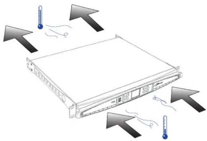
The ventilation openings must not be impeded by any item, keep a distance of at least 50 cm from the front and rear ventilation openings of the amplifier.
T Series implements a forced-air cooling system to maintain constant operating temperatures. Air enters from the front panel, exiting at the back of the amplifier.
The cooling system features variable-speed DC fans controlled by the heat sink mounted sensors. This ensures that fan noise and internal dust accumulation are kept to a minimum.
In the rare case of overheating, the amplifier is protected by limiting the output power to levels that can be sustained at the actual ambient temperature.
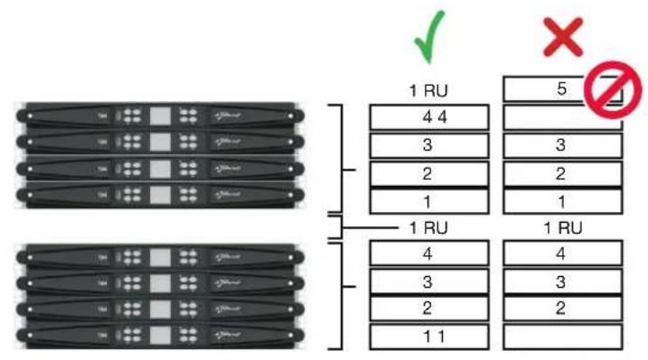
T Series amplifiers can be stacked one on top of the other, leave one rack unit empty every four to guarantee adequate air flow.
Cleaning
Use a dry cloth for cleaning the chassis and the front panel. Air filter cleaning should be scheduled in accordance with the dust levels in the amplifier's operating environment.
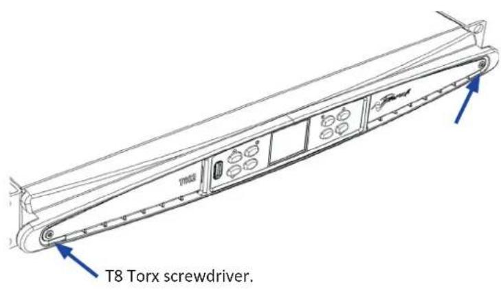
In order to take out the filters remove the 2 front covers by unscrewing the two T8 Torx screws.
Use compressed air to remove the dust from filters, or wash it with clean water (let the filters dry thoroughly before reinstalling them).
AC Mains Supply
T Series amplifiers implement a universal switching mode power supply with power factor correction operating in the range from 100 V_AC up to 240 V_AC ± 10% .
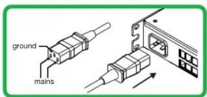
AC mains connection is in the rear panel through the IEC C20 inlet, the approved power cord is provided.
Connections
Signal Grounding
There is no ground switch or terminal on the T Series amplifier. The unit's signal grounding system is automatic. In order to limit hum and/or interference entering the signal path, use balanced input connections.
In the interests of safety, the unit MUST always operate with electrical safety earth connected to the chassis via the dedicated Protective Earth wire.
Input connections
Two channel version
- 2 x XLR female (Analog input 1, and 2)
- 2 x XLR male (Analog 1 and 2 link output)
Four channel version
- 4 x XLR female (Analog input 1, 2, 3, and 4)
Output connections
Two channel version, right to left:
- 2 x Speakon NL-4 (channel 1+2 and channel 2+n.c.)
Four channel version, right to left: - 2 x Speakon NL-4 (channel 1+2 and channel 3+4)


Digital Audio Input connection

Digital input is supported via AES3 (AES/EBU) and Dante™ standard protocols (non A models only).
The AES3 input is on a standard Neutrik XLR female. The AES3 connection carries a channel pair through a 110 Ω nominal impedance wire in the form of a balanced (differential) digital signal: in AES3 XLR connectors the identification of hot and cold pins is not an issue; take care to never tie pin 2 or pin 3 (balanced signals) to pin 1 (ground).
There is also a fault tolerant active repeater for the AES3 input available on a Neutrik XLR male connector.
T Series amplifiers accept 4 Dante/AES67 channels over two Neutrik Ethercon connectors (non A models only). There are three operating modes: 2in x 2out @ 96kHz (default), 4in x 4out @ 48kHz, 4in x 0out @ 96kHz. Cabling must comply to TIA/EIA-568-B and adopt the T568B scheme pinout.
A computer running Dante ^TM Controller can be used in order to configure audio networking. Dante ^TM Controller is a software application that manages devices on the network. T Series amplifiers are automatically discovered and displayed in Dante ^TM Controller with the default identifier: MODELNAME-SERIAL (e.g. T602-00042069).
Basic Operations
Front Panel

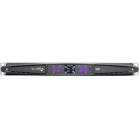
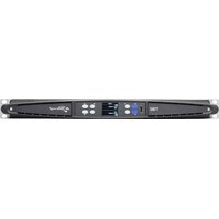
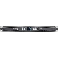
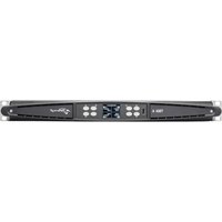
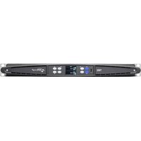
The T Series' front panel features a high brightness 1.8" TFT Color display, 8 RGB backlit pushbuttons, and a USB port.
Navigating the menu

Get acquainted with the menu structure printed on the foldout cover of this guide.
When entering the various screens some of the buttons will be lit, indicating the availability of a usable function.
The 4 buttons closest to the display are used to select the channel(s), multiple channels can also be selected at once.
When the cogwheel icon is shown on the top right corner of the display, pressing and holding the top right bottom 2 for 2 seconds will prompt the options menu.
The leftmost pushbuttons 5 are used to navigate through the different screens.
The CH3 ③, CH4 ④ buttons are sometimes used to cancel or confirm actions.
The rightmost pushbuttons ^6 are used to edit values. If held pressed they will accelerate and speed up the process.
Switching the amplifier On

Once properly powered (power cord inserted, sectioning breaker closed), if it was ON when it lost power, then the amplifier will turn ON and pass audio within 10 s.
In order to toggle the amplifier between ON and STANDBY keep pressed button 1 for 2 seconds.
Output Mute

Through this page, it is possible to mute each channel independently. In order to mute a channel (or a pair of bridged/joined channels) simply press the channel button. The VU meter will be replaced by a "MUTE" text and the channel pushbutton's color will turn to amber.
Speaker Level

A gain value appears on the screen and the amplifier's CH numbers are replaced with the speaker's letters.
By pressing the channel button the outputs that are part of the same speaker are selected, the channel buttons will blink and a value text is highlighted. Press the edit buttons ⑥ in order to edit the selected values
Press and hold the cogwheel button ② to activate the stepsize selection screen, and use the edit buttons ⑥ to toggle between 0.1, 0.5, 1.0dB increments.
Speaker Delay
A delay value appears on the screen and the amplifier's ch numbers are replaced with the speaker's letters.
By pressing the channel button the outputs that are part of the same speaker are selected, the channel buttons will blink and a value text is highlighted. Press the edit buttons 6 in order to edit the selected values.
Press and hold the cogwheel button ② to activate the stepsize selection screen, use the CH1 ① button to toggle between the available units (s, m, ft), and use the edit buttons ⑥ to toggle between 0.1, 0.5, 1.0, 10 ms; 0.1, 0.5, 1.0, 10 ft; 0.1, 0.5, 1.0, 10 m increments.
Matrix
The selected input appears on the screen and the amplifier's ch numbers are replaced with the speaker's letters.
By pressing the channel button the outputs that are part of the same speaker are selected, the channel buttons will blink and a value text is highlighted. Press the edit buttons ^6 in order to choose between the following: INPUT 1, INPUT 2, INPUT 3, INPUT 4, INPUT 1+2, INPUT 3+4.
Press and hold the cogwheel button ② to activate the custom mix screen, where it is possible to mix the inputs independently.
Source Select
The active sources of the 4 inputs appear on the screen and the amplifier's ch numbers are replaced with the input numbers.
By pressing any channel button its input priority list is selected, pressing the CH1 button ① will toggle the backup state (ON/OFF).
Press the CH2 button ② to scroll through the sources (ANL, AES3, DNT).
Press the edit buttons 6 in order to move the selected source in the list.
Snapshot
Through this screen. it is possible to recall a snapshot from the local memory.
Press and hold the CH2 pushbutton ^2 to activate the preview mode.
Output Config
Through this screen, it is possible to Bridge/Unbridge the outputs of the T Series amplifier.
Pressing any of the CH buttons will select the related channel.
Joined channels must be split prior to performing briging/unbridging.
Speaker Preset
Through this screen, it is possible to check the presets that are currently loaded onto each channel.
Presets can be sourced both from the internal memory and from an external USB drive.
Preset selection is a guided configuration through which the amplifier will ask the user to select the brand, the family, the model, and its application. Once the application is selected and confirmed, channel buttons 1/2/3/4 ①→④ buttons can be used to select the output channel onto which the preset should be loaded.
Network Configuration
This screen portrays the amplifier's current network configuration. The CH4 pushbutton is lit and can be used to change the configuration.
Use the CH1 ① and CH2 ② buttons to choose between "AMP STATUS" and "DANTE STATUS" respectively (non A models only).
It's then possible to toggle between "AUTO IP" and "STATIC IP", when the latter is selected, the CH1 ① and CH2 ② buttons are used to navigate across the digits, whilst the edit buttons ⑥ are used to edit the single digits.
Node Info
Through this screen, it is possible to display node information. Use the edit buttons ⑥ to navigate the available pages.
If the cogwheel button ^2 is pressed for more than 2 seconds a submenu will open, containing the following: "LOCK INTERFACE", "LCD BRIGHTNESS", "REMOVE GROUPS", "RESET PROCESSING".
LOCK INTERFACE: Local lock screen, enter a 6 digit password to lock. The locked screen shows only the main view, the standby and navigation buttons are disabled. (Passepartout: 441144)
LCD BRIGHTNESS: Choose between 3 different display brightness levels.
REMOVE GROUPS: Removes the amplifier from any group, removes also the processing associated with that group. One typical use for this function is to remove any group that is present within the amplifier from any previous operation, while preserving the preset and the snapshot list.
RESET PROCESSING: Reset to the factory default processing parameters (unmuted outputs, straight signal routing, no crossovers, EQ=flat, input to output gain=32dB, no limiters, and delay=0ms).
FW Update
Updating the firmware can be done through Armonía.
During the firmware update, the display will show an “Updating Firmware” message, and a bar will show the progress through the various phases.
Networking
T Series amplifiers support Dante networking (non A models only). The two-gigabit ports internally connected via a Gigabit switch to simplify wiring and eliminate the need for external network switches in small systems. Control and audio are flowing on both ports. The amplifier can be configured for redundancy using AES3 and/or analog inputs; it can also use a redundant source device on Dante. However, it can't use two audio networks, so never connect a T Series to the secondary network if there is one in the system.
IP Addressing
Factory default network settings are AUTO IP.
STATIC IP policy can also be adopted and configured through ArmoníaPlus or the display panel.
Both ArmoníaPlus and the T Series must belong to the same subnet. If a DHCP server is not active within the network, the amplifier platform initiates a stateless address auto-configuration (i.e. Zero-configuration networking methodology – Zeroconf): it self assigns a local numeric network address (of the type 169.254.x.y with a subnet mask 255.255.0.0) and automatically distributes and resolves the hostnames of the networking devices.
As a rule of thumb, turn the DHCP server on before connecting the amplifiers.
When the amplifier discovers a DHCP server on the network, it negotiates the networking parameters.
ArmoníaPlus System Manager
ArmoníaPlus System Manager is the default interface that allows system setting and customization of the T Series amplifiers.
ArmoníaPlus can be installed on a PC running Windows (XP SP3 and higher).
Download ArmoníaPlus System Manager for free from the dedicated website:
https://www.powersoft.com/en/software/armoniaplus/
T302, T304, T302 A, T304 A
T602, T604, T602 A, T604 A
T902, T904, T902 A, T904 A
Quality & After Sales Manager

https://www.powersoft.com/en/software/armoniaplus/
T302, T304, T302 A, T304 A
T602, T604, T602 A, T604 A
T902, T904, T902 A, T904 A
Quality & After Sales Manager

https://www.powersoft.com/en/software/armoniaplus/
T302, T304, T302 A, T304 A
T602, T604, T602 A, T604 A
T902, T904, T902 A, T904 A
Quality & After Sales Manager

Pour les questions de conformité uniquement: compliance@powersoft.it
https://www.powersoft.com/en/software/armoniaplus/
T302, T304, T302 A, T304 A
T602, T604, T602 A, T604 A
T902, T904, T902 A, T904 A
Quality & After Sales Manager

https://www.powersoft.com/en/software/armoniaplus/
T302, T304, T302 A, T304 A
T602, T604, T602 A, T604 A
T902, T904, T902 A, T904 A
Quality & After Sales Manager

(Scandicci (Fi 50018
Italy
T302, T304, T302 A, T304 A
T602, T604, T602 A, T604 A
T902, T904, T902 A, T904 A
Quality & After Sales Manager

T302, T304, T302 A, T304 A
T602, T604, T602 A, T604 A
T902, T904, T902 A, T904 A
Quality & After Sales Manager

https://www.powersoft.com/en/software/armoniaplus/
重要安全说明
符号和含义
powersoft.com/en/product-repair/



WEEE指令 欧盟符合性声明
T302, T304, T302 A, T304 A
T602, T604, T602 A, T604 A
T902, T904, T902 A, T904 A
用途:专业音频放大器
Quality & After Sales Manager

仅限法规遵从性问题:compliance@powersoft.it
预备操作
包装清单
箱内含有:
1xT系列放大器。
3 x IEC电源线(区域特异性)
1x本用户指南
位置
将T系列放大器安装在通风良好的机柜中。
把前后支架固定到架子上。
把交流主接头连接到电路断路器。
放大器的安装位置应远离电磁场发射装置。
避免把放大器放到靠近热源的位置。
冷却
https://www.powersoft.com/en/software/armoniaplus/
Location
Cooling
natural_image
Illustration of a server rack with temperature indicators and hanging cables, no text or symbols presentExposing the Filters
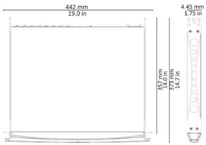
Dimensions
Pinouts
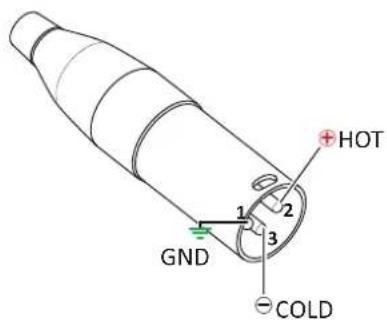
Analog/AES3 input XLR-M pinout
Pin# Terminal
1 Ground (GND)
2 Positive (+)
3 Negative (-)
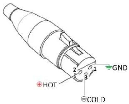
Analog/AES3 link XLR-F pinout
Pin# Terminal
1 Ground (GND)
2 Positive (+)
3 Negative (-)
Network Connector RJ45 pinout
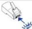
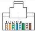
Color code (TIA/EIA-568-B) Pin
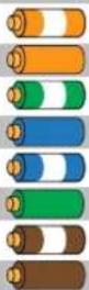
ORANGE / WHITE 1
ORANGE 2
GREEN / WHITE 3
BLUE 4
BLUE / WHITE 5
GREEN 6
BROWN / WHITE 7
BROWN 8
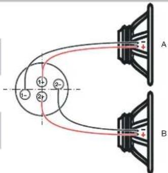
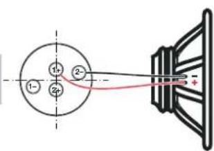
Output NL4 Speakon-F pinout
Single Ended
1+ Speaker A positive terminal
1- Speaker A negative terminal
2+ Speaker B positive terminal
2- Speaker B negative terminal
Bridged
1+ Speaker positive terminal
2- Speaker negative terminal
Menu system
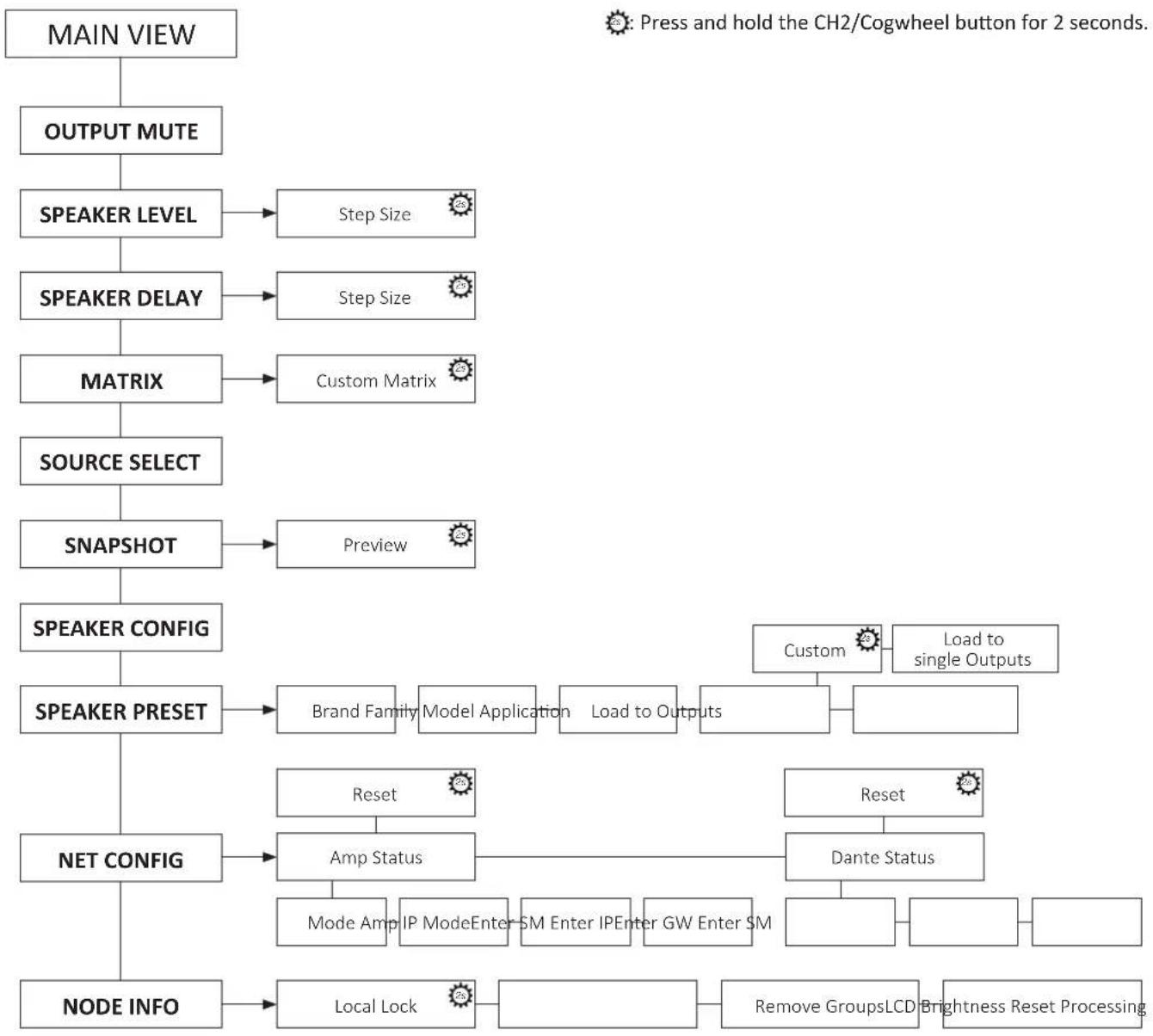
flowchart
graph TD
    A["MAIN VIEW"] --> B["OUTPUT MUTE"]
    B --> C["SPEAKER LEVEL"]
    C --> D["Step Size"]
    C --> E["Step Size"]
    C --> F["Custom Matrix"]
    F --> G["SOURCE SELECT"]
    G --> H["SNAPSHOT"]
    H --> I["Preview"]
    I --> J["Brand Family"]
    I --> K["Model Application"]
    I --> L["Load to Outputs"]
    L --> M["Reset"]
    M --> N["Amp Status"]
    N --> O["Mode Amp"]
    N --> P["IP ModeEnter SM"]
    N --> Q["Enter IPEnter GW"]
    N --> R["Enter SM"]
    L --> S["Custom"]
    S --> T["Load to single Outputs"]
    U["NET CONFIG"] --> V["Node INFO"]
    V --> W["Local Lock"]
    W --> X["Remove GroupsLCD Brightness Reset Processing"]
Front Panel

natural_image
Front panel of a T604 industrial control unit with labeled buttons and ports (no readable text beyond branding)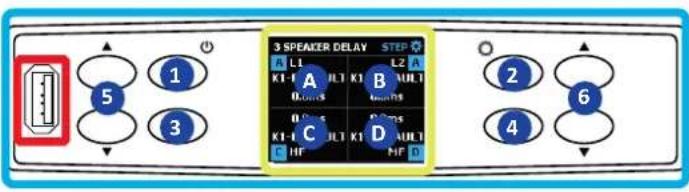
Control Panel
1 CH1 - ON/STDBY (2s hold)
2 CH2 - COGWHEEL (2s hold)
3 CH3 (4 CH models) - Back
4 CH4 (4 CH models) - Apply
5 Toggle between screens
6 Value edit
USB Port
Speaker presets
Display
A CH1
B CH2
C CH3 (4 CH models)
D CH4 (4 CH models)
Rear Panel
T302 - T602 - T902

T304 - T604 - T 904

Output section
T302 - T602 T304 - T604
7 CH1 (1+/-) | CH2 (2+/-) CH1 (1+/-) | CH2 (2+/-)
8 CH2 (1+/-) | n.c. (2+/-) CH3 (1+/-) | CH4 (2+/-)
AES3
9 AES3 IN (1GND/2+/3-)
10 AES3 OUT (1GND/2+/3-)
Input section
T302 - T602 T304 - T604
11 Input 1 (XLR-F) Input 1 (XLR-F)
12 Input 1 (XLR-F) Input 2 (XLR-F)
13 Link 1 (XLR-M) Input 3 (XLR-F)
14 Link 2 (XLR-M) Input 4 (XLR-F)
Network Connectors
15 ETH 1 (RJ45)
16 ETH 2 (RJ45)
AC Mains Connector
IEC C19
Powersoft HUMAN AUDIO EXPERIENCE
POWERSOFT S.P.A.
Via E. Conti, 5 - Scandicci (FI) 50018 - Italy
support@powersoft.com
+39 055 73 50 230
+39 055 73 56 235
- Important Safety Instructions
- Common symbols and meanings
- Safety Warnings
- Warranty and Technical Service
- EC Declaration Of Conformity
- Regulatory Compliance Statements
- Europe
- USA
- FCC Supplier's Declaration of Conformity
- FCC Compliance Statement
- Canada
- Canadian Caution
- ICES-003 Class A Notice
- Radiation Exposure Statement
- Preliminary operations
- Package list
- Location
- Cooling
- Cleaning
- AC Mains Supply
- Connections
- Signal Grounding
- Input connections
- Output connections
- Digital Audio Input connection
- Basic Operations
- Front Panel
- Navigating the menu
- Switching the amplifier On
- Output Mute
- Speaker Level
- Speaker Delay
- Matrix
- Source Select
- Snapshot
- Output Config
- Speaker Preset
- Network Configuration
- Node Info
- FW Update
- Networking
- IP Addressing
- As a rule of thumb, turn the DHCP server on before connecting the amplifiers.
- ArmoníaPlus System Manager
- 重要安全说明
- 符号和含义
- WEEE指令 欧盟符合性声明
- 预备操作
- 包装清单
- 位置
- 冷却
- Pinouts
- Analog/AES3 input XLR-M pinout
- Analog/AES3 link XLR-F pinout
- Network Connector RJ45 pinout
- Output NL4 Speakon-F pinout
- Menu system
- Control Panel
- USB Port
- Display
- Rear Panel
- Output section
- AES3
- Input section
- Network Connectors
- AC Mains Connector
- Powersoft HUMAN AUDIO EXPERIENCE
Brand : Powersoft
Model : T304
Category : Inverter