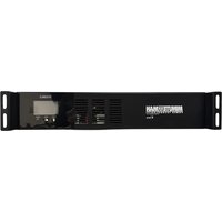
SR1000RMLCD - Uninterruptible power supply Minuteman - Free user manual and instructions
Find the device manual for free SR1000RMLCD Minuteman in PDF.


User questions about SR1000RMLCD Minuteman
0 question about this device. Answer the ones you know or ask your own.
Ask a new question about this device
Download the instructions for your Uninterruptible power supply in PDF format for free! Find your manual SR1000RMLCD - Minuteman and take your electronic device back in hand. On this page are published all the documents necessary for the use of your device. SR1000RMLCD by Minuteman.
USER MANUAL SR1000RMLCD Minuteman
natural_image
Black MINUTE/MAN Power Technology System 2010/2011 unit with digital display and ventilation slots (no readable text or symbols beyond branding)Table of Contents
Introduction ...... 1
Installation 3
Operation 10
Troubleshooting 12
Replacing the Battery Module ...... 14
Specifications 17
Warranty 18
A1. Declaration of Conformity ..... 21
Introduction
Thank you for purchasing a MINUTEMAN power protection product. It has been designed and manufactured to provide many years of trouble-free service.
IMPORTANT SAFETY INSTRUCTIONS SAVE THESE INSTRUCTIONS!
Please read this manual and comply with all warnings and instructions before installing your SR Series UPS as it provides important information that should be followed during installation and maintenance of the UPS allowing you to correctly set up your UPS for the maximum safety and performance.
WARNINGS AND CAUTION STATEMENTS:
Risk of Electrical Shock. There are hazardous live parts inside these power supplies that are energized from the battery even when the AC input is disconnected. Do not attempt to disassemble the UPS as it contains no user serviceable parts except for battery replacement. Repairs and Battery replacement must be performed by QUALIFIED SERVICE PERSONNEL ONLY.
This UPS series is only intended to be installed in an indoor temperature-controlled environment that is free of conductive contaminants, dust or direct sunlight. Never install the UPS near liquids, damp locations or where there is potential for contact with liquids.
The ambient operating temperature range for this UPS series is 32^ 104^ ( 0^ 40^ )
To ensure the proper ventilation and cooling of the UPS, do not block any of the ventilation cutouts on the UPS. Adequate space must be provided around all sides of the UPS to allow for proper air flow.
Only connect the UPS to a two-pole, three-wire grounded AC wall outlet that includes appropriate branch circuit protection (circuit breaker or fuse) in accordance with NEC ANSI/NFPA 70 and CEC, Part I, C22.2. Do not plug the UPS into itself or use extension cords, adapter plugs, or surge strips as it may damage the UPS or connected devices.
To reduce the risk of fire, connect the UPS only to a utility power circuit provided with 20 Amps maximum branch circuit, over-current protection in accordance with the NEC, ANSL/NFPA 70.
Batteries can present a risk of electrical shock. Observe proper cautions and do not bridge the battery terminals at any time. Follow all precautions and instructions for battery replacement and disposal in the BATTERY REPLACEMENT section of this manual.
Installation
Package Contents:
UPS
USB Communications Cable
User Manual
Rackmount Ears (Installed)
Product Registration
Before installation of your new UPS, please take a moment to verify all the package contents. If there is anything missing, please contact Minuteman Power Technologies.
After removing your UPS from its carton, it should be inspected for damage that may have occurred in shipping. Immediately notify the carrier and place of purchase if any damage is found. Warranty claims for damage caused by the carrier will not be honored unless notified at the time of delivery. The packing materials for the UPS are carefully designed to minimize any shipping damage. In the unlikely case that the UPS needs to be returned to the manufacturer, please use the original packing material. Since the manufacturer is not responsible for shipping damage incurred when the system is returned, the original packing material is inexpensive insurance. PLEASE SAVE THE PACKING MATERIALS!
Placement of UPS
The external vents and openings on the UPS are provided for ventilation. To ensure reliable operation of the UPS and to protect the UPS from overheating, these vents and openings must not be blocked or covered. Do not insert any object into any of the vents or openings that may hinder the ventilation.
Install the UPS system in a well-ventilated area, away from direct sunlight, excess moisture, heat, dust, flammable gas or explosives. Leave adequate space (at least 20cm) at the front and rear of the UPS system for proper ventilation. If wallmounting, do not mount the UPS system with its front or rear panel facing down at any angle.
Connect the Internal Battery Module:
These UPSs are shipped with internal batteries disconnected. Please read all WARNINGS and CAUTIONS before attempting to connect the batteries.
Use two or more people when installing the UPS, the UPS is extremely heavy.
- Remove the UPS from the shipping box and place on a flat surface.
NOTE: A Philips srewdriver is required for removing or installing the battery door.
-
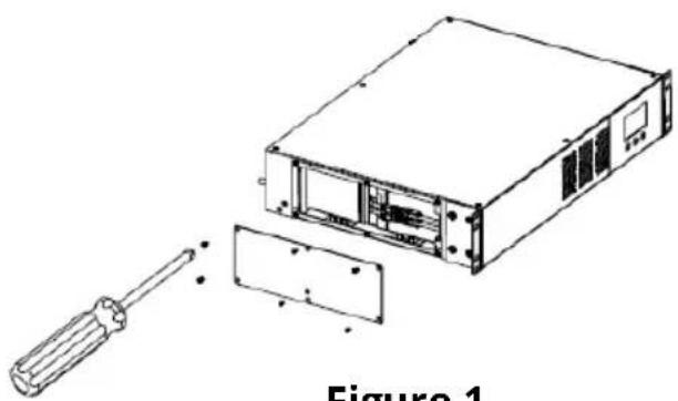
Remove the six anchor screws holding the battery door on the left hand side of the UPS. Pull the panel off and set it aside (FIG. 1).
-
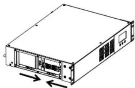
Verify proper polarity of the Anderson connectors. Slide the connectors together and press both ends until the connectors snap into place. (FIG. 2).
NOTE: Some sparking may occur this is normal.
-
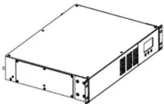
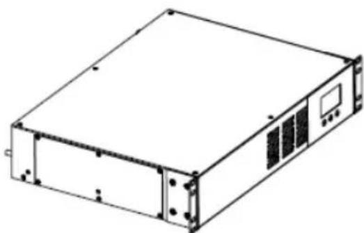
Re-install the battery panel on the UPS, using the six anchor screws(FIG. 3).
-
Connection of the batteries is complete.
natural_image
Technical line drawing of an electronic device with a screwdriver inserted, showing internal components and part outline (no text or symbols)Figure 1
natural_image
Line drawing of a server rack unit with ventilation slots and drive bays (no text or symbols)Figure 2
natural_image
Line drawing of a rectangular electronic device with mounting holes and ventilation slots (no text or symbols)Figure 3
Once the internal battery module of the UPS is attached, connect the UPS to utility power, following the product safety warnings. The UPS will automatically begin charging its batteries without having to power on the unit. Allow the unit to charge its batteries for a minimum of 8 hours before use.
Rackmount Installation:
This UPS series comes with mounting brackets for the standard 19" (46.5cm) rack pre-installed on the UPS.
Rail Kits for 4-post racks and cabinets are also available. The screws for mounting the UPS to the rack are included.
CAUTION! DO NOT USE THE MOUNTING BRACKETS TO LIFT THE UPS. The mounting brackets are ONLY for securing the UPS to the rack.
-
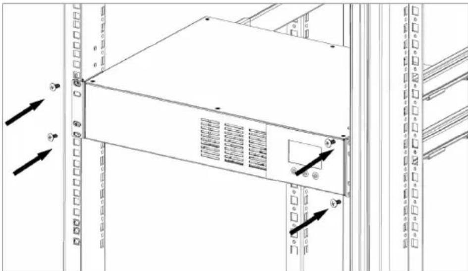
Mount the UPS into the rack and secure with the four retaining screws provided. Use two or more people when installing the UPS, the UPS is extremely heavy. Do not move the rack after the units have been installed. The rack may become unstable due to the weight distribution. (FIG. 4)
-
The Rackmount Configuration is complete. See Connecting your Equipment.
natural_image
Diagram of a server rack with directional arrows indicating ports or connections (no text or symbols present)Figure 4
Wallmount Installation:
Minuteman offers an optional wallmount bracket kit which allows the installation of the SR Series UPS to a wall. The kit includes two wall mounting brackets, ten retaining screws and the wallmount template. Use two or more people when installing the UPS as it is extremely heavy.
The UPS side panels have mounting bracket screw holes for attaching the wall mounting bracket to the UPS.
- Once the location of the UPS has been determined, place the UPS on a flat surface and remove the rackmount brackets from the UPS.
- Use the enclosed template to mark the screw hole position on the wall.
- Attach the four retaining screws to the wall and make sure that all of the retaining screws are screwed into structural material. Then clean the area of any loose material. Do not tighten the retaining screws all the way, leave approximately 3/8" of the retaining screws sticking out. CAUTION, you should always wear protective gear for your hands and eyes when operating power tools.
- Align the wall mounting brackets with the wall mounting bracket screw holes on the side panels of the UPS and attach with the six retaining screws.
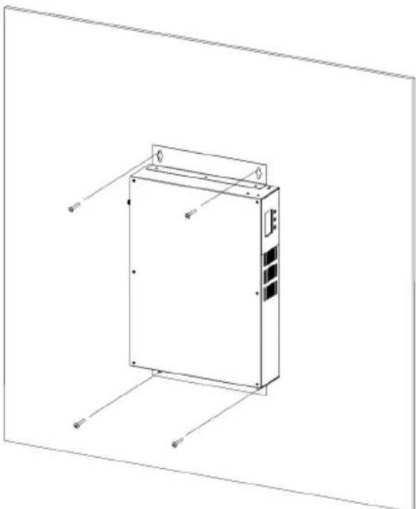
NOTE: The UPS must be installed in the proper upright position. If the UPS is not installed in the proper position, the batteries could be damaged. The correct orientation has the LCD display, when looking at the UPS on the wall, on the right-hand side on the top. (FIG. 5)
-
Position the UPS, so that the mounting bracket keyed holes line up with the four retaining screws. Slide the UPS down until it's resting securely on the four retaining screws.
-
Tighten the four retaining screws to secure the UPS to the wall.
-
The Wallmount Configuration is complete.
natural_image
Technical line drawing of a rectangular electronic device with mounting brackets and control panel (no text or symbols)Figure 5
UPS Back Panel Connections:
text_image
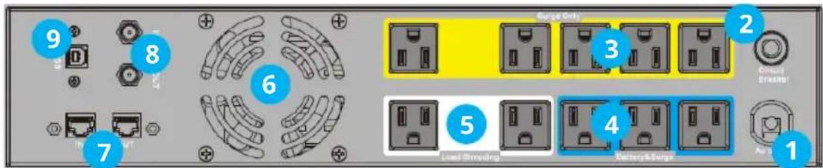
9 8 6 7 Surge Only 3 2 Circuit Drainer 5 4 Level Streaming Battery&Surge 11) Input power cord connection
2) Input circuit breaker
3) Surge-only protected receptacles
4) Surge & Battery protected receptacles
5) Master Receptacles (Surge & Battery protected)
6) Cooling fan
7) RJ45 Ethernet surge protection (10/100/1000Mbit)
8) Coax surge protection
9) USB communication port
Front Panel Display and Controls:
text_image
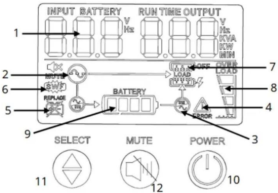
INPUT BATTERY RUN TIME OUTPUT 1 V Hz V Hz KVA KW MIN 2 NOTE LOAD OFF OVER LOAD 6 SWF LOAD 5 REPLACE BATTERY ERROR 9 SELECT MUTE POWER 11 12 10The front panel controls will have the following indicators and function buttons:
- Realtime Display (Input / Output)
- AC Mode Icon
- On Battery Icon
- "Error" Icon
- Replace Battery Icon
- Site Wiring Fault (SWF) Icon
- Load Shedding Status
- Load Status
- Battery Capacity
- "POWER" - On/Off/Test Button
- "SELECT" - Menu Scroll Button
- "MUTE" - Alarm Silencer Button
Operation
Connect the UPS to AC utility power and allow a minimum of 8 hours to charge the internal batteries.
Connect all the devices to be protected into the desired receptacles.
Battery & Surge Receptacles:
Provides power to critical devices during a blackout
Surge Only Receptacles:
Provides spike and surge protection for devices that do not require battery backup.
Load Shedding:
The outlets labeled “Load-Shedding” offer battery and surge protection but can be independently turned off and on through the SentryHD software, installed on a connected computer. The default setting for these outlets will be “On”.
Press and hold the "POWER" button until the UPS sounds one beep then release. The UPS will initiate a five-second self-test to check the internal systems and batteries.
If a fault or bad battery is detected, the UPS will sound an alarm and an associated error code for the fault on the LCD Display. Once the self-test is cleared the UPS will begin providing power to connected devices.
Input Voltage Sensitivity Adjustment:
The input voltage window of the SR Series can be adjusted if the UPS is transferring to battery mode due to inconsistent utility power. With the UPS off and connected to utility power, press and hold the Scroll button for 5 seconds. This setting has two options to adjust the nominal input voltage range before UPS transfers to battery mode. The default input voltage range of the UPS is 87-142VAC. Setting the UPS to Option 1 lowers the input voltage range to 82-142VAC. To return the setting to its factory default, repeat the process by holding the Scroll button for 5 seconds with the UPS off but connected to utility power.
Surge Protection Ports:
The SR series comes with both RJ45 and Coax surge protection ports.
Use the input port for the connection from the source and the output port to connect the protected devices. Use of these ports are not required for the operation of the UPS.
USB Communication Port:
Use the USB port, with the included USB communications cable, to connect to a computer if using Minuteman's SentryHD software, (available via free download from: www.
minutemanups.com/minuteman-software-download-center/), and follow the instructions in the software manual for installation. SentryHD is not required for the operation of the UPS.
Troubleshooting
Alarms:
On Battery - When the UPS goes to Battery Mode, it will sound a single beep once every 10 seconds until the UPS reaches "Low Battery Warning" or AC power returns.
Low Battery Warning – Once the UPS reaches “Low Battery Warning”, it will sound 2 beeps every 5 seconds and Error Code: E07 will be displayed on the LCD panel until it shuts down for “Low Battery Cut-off” or AC power returns.
Weak/Bad Battery – When the UPS detects a weak or bad battery, the alarm will sound 3 beeps every 5 minutes and Error Code: E06 will be displayed on the LCD panel. This alarm will remain until the battery is recharged, replaced or connected.
Overload – When the UPS detects an overload, the alarm will sound continuously and Error Code: E02 will be displayed on the LCD panel. This alarm will continue until the overload is removed.
Fault – When the UPS detects an internal fault, the alarm will sound continuously and Error Code: E04 will be displayed on the LCD panel. This alarm will remain until the UPS is powered off and serviced.
| Symptom / Error Code | Cause / What to Do |
| UPS will not turn on | Press the “POWER” button and release after one beep. |
| UPS operates in battery mode only, even with AC present. | Reset the input circuit breaker by pressing the plunger back in. If the input circuit breaker trips after the UPS restarts, reduce the load on the UPS. |
| The AC Normal Icon is blinking and the alarm is silent. | The UPS is in Boost Mode. It is performing its intended function |
| The UPS does not provide the expected runtime. | Charge the batteries for 8 hours and retest. If the runtime is still less than expected, the batteries may need to be replaced. |
| The AC Normal Icon is illuminated but there is no output. | Disconnect the computer cable from the UPS and press the “POWER” button. If the UPS works normally, the software has control of the UPS. |
| The “ERROR!” Icon is illuminated and there is a constant alarm. | The UPS has an internal problem. Call for service. |
| Error Code: E01The UPS is shut down | The UPS has detected a short circuit on its output. Check the attached load. |
| Error Code: E02Overload Icon is illuminated and there is a constant alarm. | Check the specifications of the connected devices and remove part of the load. If the UPS shuts down because of an overload, the UPS must perform an inverter function or a Self-Test to clear the overload alarm. |
| Error Code: E03Over-temperature shutdown | The internal or ambient temperature has exceeded the safe operating range for the UPS. Refer to the product specifications. |
| Error Code: E04Invert/Output failure - shutdown | The UPS has an internal fault. Call for service. |
| Error Code: E05Charger Failure Warning | The battery charger has failed. Call for service. |
| Error Code: E06Weak/Bad Battery Icon is illuminated | Check the battery connections and charge the batteries for 8 hours and re-test. If no change in the alarm, the batteries may need to be replaced. Call for service. |
| Error Code: E07Low Battery Warning | The UPS battery reserve is low. This condition will continue until AC power returns or the UPS shuts down from battery exhaustion. |
| Error Code: E08SWF icon is illuminated | Have a qualified electrician correct the service wiring. |
Replacing the Battery Module
The batteries provided with the SR Series UPS will provide several years of service. Replacement of the battery module should be performed by qualified service personnel only. Review all the warning and caution statements prior to attempting battery module replacement.
When replacing batteries, use the exact same type and number of batteries or battery modules.
CAUTION! Do not dispose of batteries in a fire. The batteries may explode.
CAUTION! Do not open or mutilate batteries. Released electrolyte is harmful to the skin and eyes. It may be toxic. CAUTION! A battery can present a risk of electrical shock and high short-circuit current. Contact with any part of a grounded battery can result in electrical shock. The following precautions should be observed when working on batteries:
a) Remove watches, rings, or other metal objects.
b) Use tools with insulated handles.
c) Wear rubber gloves and boots.
d) Do not lay tools or metal parts on top of batteries.
e) Disconnect charging source and load prior to installing or maintaining the battery.
f) Remove battery grounds during installation and maintenance to reduce likelihood of shock. Remove the connection from ground if any part of the battery is determined to be grounded.
The input utility receptacle shall be installed near the equipment and shall be easily accessible.
If you need assistance with the disposal of the batteries, please contact Minuteman at service@minutemanups.com for additional details and support or call 800.238.7272.
To maintain the optimal performance of the SR Series UPS, it is important to only use battery modules designed to work with the SR Series. Using third-party or inferior batteries will affect the negatively affect the performance and life of the UPS.
Replacement battery modules are available from Minuteman at https://minutemanups.com/buy-ups-replacement-batteries/ or by contacting Minuteman service at 800.238.7272.
Powering off the UPS is not required to replace the battery module. Remove all watches, rings or the metal objects during the process.
Use two or more people when replacing the internal battery modules, the UPS is extremely heavy.
- Remove the UPS from rack or wall installation and place it on a flat surface.
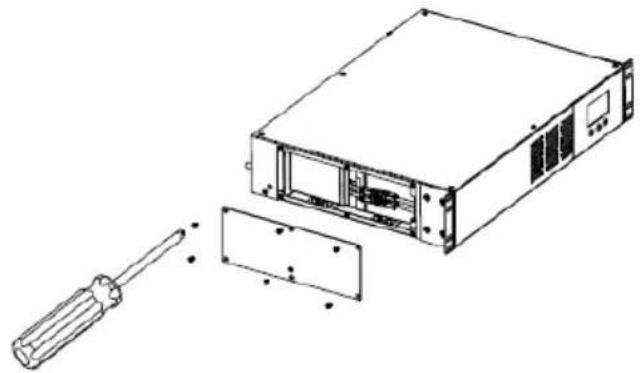
NOTE: A Philips srewdriver is required for removing or installing the battery door.
-
Remove the six anchor screws holding the battery door on the left hand side of the UPS. Pull the panel off and set it aside (FIG. 6).
-
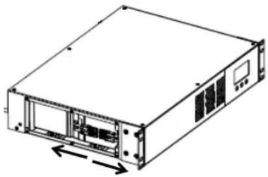
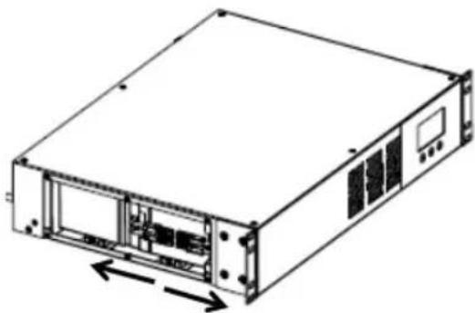
Disconnect the internal battery module by spearating the Anderson connectors. (FIG. 7).
NOTE: Some sparking may occur this is normal.
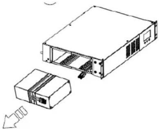
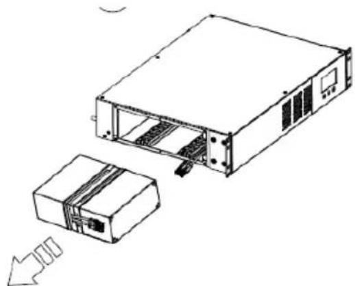
- Remove the internal battery module from the UPS by pulling on the tab or by using the module connector.
(FIG. 8)
-
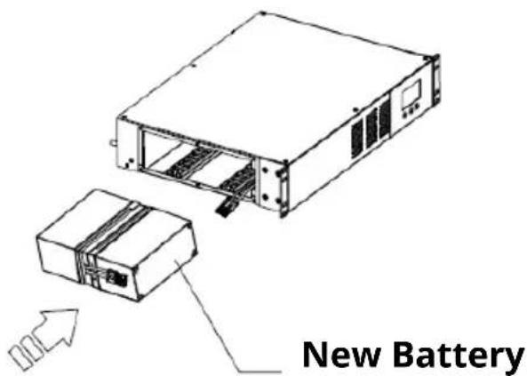
Insert the new battery module. (FIG. 9).
-
Verify proper polarity of the Anderson connectors. Slide the connectors together and press both ends until the connectors snap into place. (FIG. 10).
-
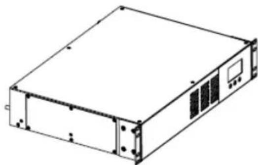
Re-attach the side panel and reinstall the UPS. (FIG. 11)
natural_image
Technical line drawing of a server rack with a screwdriver inserted, showing internal components and mounting holes (no text or symbols)Figure 6
natural_image
Line drawing of a server rack unit with internal components and directional arrows indicating movement (no text or symbols)Figure 7
natural_image
Technical line drawing of a device housing with internal components and an external component, showing no text or symbols.Figure 8 Figure 9

text_image
New Battery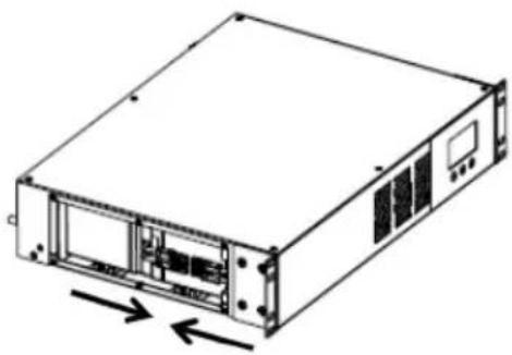
natural_image
Line drawing of a server rack unit with internal components and two directional arrows indicating movement (no text or symbols)Figure 10
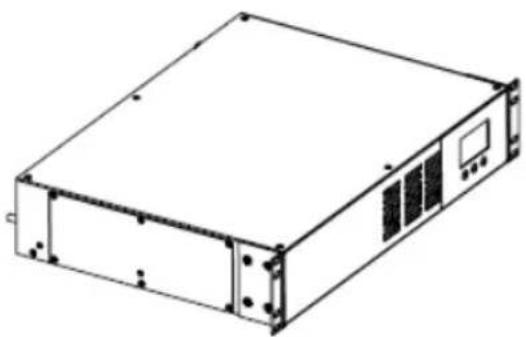
natural_image
Isometric line drawing of a rectangular electronic device with mounting brackets and ventilation slots (no text or symbols)Figure 11
Specifications:
| Feature/Specification | SR1000RMLCD | SR1500RMLCD |
| Rating | ||
| Apparent Output Power | 1000VA | 1440VA |
| Active Output Power | 600Watts | 900Watts |
| Power Factor | 0.6 | 0.625 |
| Topology Line-Interactive | ||
| Type | Rackmount/Wallmount | |
| Agency Approvals | cTUVus (Conforms to UL 1778:2014/R:2024-04 and CSA C22.2 No. 107.3:2014/U2:2023-04), FCC Class B, Energy Star 2.0, U.S. DOE 10 CFR Part 430 | |
| Green Compliance | RoHS2 (EU Directive 2011/65/EU) | |
| Input | ||
| Input Voltage (Typical) | 120VAC | |
| Voltage Range | 87 to 142VAC | |
| Frequency Range | 60Hz ±6Hz | |
| Typical Transfer Time | 6-10 ms (max 10 ms) | |
| AC Leakage Current | <1.5mA at full rated non-linear load | |
| Surge Protection | 1200 joules | |
| Output (non-battery operation) | ||
| Output Voltage (Typical) | 120VAC | |
| Voltage Range | 104 to 140VAC | |
| Frequency | 60Hz ±6Hz. | |
| Efficiency (AC-AC) | >96% at full rated linear load | |
| Output (battery operation) | ||
| Voltage | 120VAC | |
| Voltage Regulation | 120VAC ±5% until low battery warning | |
| Frequency | 60Hz ±0.5Hz unless synchronized to line | |
| Wave Form | Simulated sine wave | |
| Peak Output Voltage | ≤190Vpk at loads>100Watts | |
| Dynamic Response | ±10% at 100% load change in 30ms (Linear Load) | |
| Efficiency (DC-AC) | >70% at full linear load | |
| Battery System | ||
| Hot Swappable Battery | Yes | |
| Internal Battery | Yes | |
| DC Leakage Current | <30uA (±10uA) with no AC applied and the unit in the off position | |
| Battery Type | Sealed, non-spillable, Valve Regulated, maintenance-free, lead acid | |
| Typical Battery Runtimes (minutes) | ||
| Full Load | 2.5 minutes | 2.5 minutes |
| Half Load | 11.0 minutes | 11.0 minutes |
| Physical | ||
| Dimensions (HxWxD) | 3.4" x 17.2" x 12.6" (86*438*320mm) | |
| Weight | 26.9 lbs. (12.2Kg) | 31.3 lbs. (14.2Kg) |
Warranty:
Para Systems, Inc. (Para System) warrants this equipment, when properly applied and operated within specified conditions, against faulty materials (excluding the batteries) or workmanship for a period of three years from the date of purchase. Para Systems Inc. (Para Systems) warrants the batteries for a period of two years from the date of purchase. The customer pays for shipping the product to Para Systems. Para Systems pays ground freight to ship the product back to the customer. Replacement parts and warranty labor will be borne by Para Systems. For equipment located outside of the United States and Canada, Para Systems only covers faulty parts. The warranty shall be void if the equipment is damaged by the customer, is improperly used, is subjected to an adverse operating environment, or is operated outside the limits of its electrical specifications.
EXCEPT AS PROVIDED ABOVE, IN NO EVENT WILL PARA SYSTEMS BE LIABLE FOR DIRECT, INDIRECT, SPECIAL, INCIDENTAL, OR CONSEQUENTIAL DAMAGES ARISING OUT OF THE USE OF THIS PRODUCT, EVEN IF ADVISED OF THE POSSIBILITY OF SUCH DAMAGE. Specifically, Para Systems is not liable for any costs, including labor for on-site installation, on-site maintenance or on-site service, lost profits or revenue, loss of equipment, loss of use of equipment, loss of software, loss of data, cost of substitutes, claims by third parties, or otherwise.
Before contacting Para Systems regarding warranty service, please review the troubleshooting section of the user's manual to determine the problem can be resolved without additional assistance. If the problem can't be resolved using the Troubleshooting table, prior to contacting Para Systems customers support, please record the following information about the UPS in questions:
Model Number:
Serial Number:
Purchased From: ____
Date of Purchase: ____
After recording this information, please contact Para Systems customer support by phone at 800.238.7272 or by e-mail at: support@minutemanups.com.
Be ready to provide the information above, along with a description of the problem and Para Systems will provide instructions on how to return the unit for service, if necessary.
Additional Notices:
NOTICE: This product complies with the rules for Class B device, pursuant to Part 15 of the FCC rules for radio noise emissions from a digital apparatus.
These limits are designed to provide reasonable protection against such interference in a residential installation.
This equipment generates and uses radio frequency and if not installed and used properly, in strict accordance with the manufacturer's instructions, may cause interference to radio and television reception. If this device does cause interference to radio or television reception, which can be determined by turning the equipment off and on, the user is encouraged to try to correct the interference by one or more of the following measures:
• Reorient the receiving antenna.
- Relocate the computer with respect to the receiver.
- Move the computer away from the receiver.
- Plug the computer into a different outlet so that the computer and receiver are on different branch circuits.
- Shielded communications interface cables must be used with this product.
Life Support Policy:
Para Systems does not support the use of any of its products in life support applications where the failure or malfunction of the product can be reasonably expected to cause failure to life support devices or to significantly affect their safety or effectiveness. Furthermore, Para Systems does not recommend the use of any of its products in direct patient care.
© 2025 PARA SYSTEMS, INC.:
Minuteman Power Technologies, SR and SentryHD are owned by Para Systems, Inc. All other trademarks are property of their irrespective owners.

text_image
Energy ENERGY STARRoHS2
DoE 10 CFR Part 430
FCC Class B
TUV SUD cTUVus (UL1778)
A1. Declaration of Conformity
Standard(s) to which conformity is declared: cTUVus (Conforms to UL 1778:2014/R:2024-04 and CSA C22.2 No. 107.3:2014/U2:2023-04), FCC Class B, Energy Star 2.0, U.S. DOE 10 CFR Part 430
Manufacturer's Name: Para Systems, Inc.
Manufacturer's Address: 2850 Lake Vista Dr., Suite #110 Lewisville, TX 75067 USA
Type of Equipment: Uninterruptible Power Supply (UPS)
Models: SR1000RMLCD, SR1500RMLCD
Year of Manufacture: Beginning September 2025
I hereby declare the equipment specified above conforms to the above Directive(s).
Kevin Canole (Name) (Position) Director of Business Development
Location: Lewisville, TX USA Date: July 10, 2025
Para Systems, Inc.
2850 Lake Vista Drive, Suite #110
Lewisville, TX 75067
800.238.7272
www.minutemanups.com
34000579 RevC 202509
MINUTEOOMAN®
POWER TECHNOLOGIES
by Para Systems, Inc.
Onduleur série SR
natural_image
Black MINUTE-SMAN Power Technology Unit 50 Series device with digital display and control buttons (no readable text beyond branding)Table des matières
Présentation 1
Installation 3
Opération ......10
Dépannage ......12
natural_image
Technical line drawing of a server rack with a screwdriver inserted, showing internal components and assembly (no text or symbols)Figure 1 Figure 2
natural_image
Line drawing of a rectangular electronic device with mounting holes and control panel (no text or symbols)Figure 3
natural_image
Technical line drawing of a server rack with mounting holes and ventilation slots (no text or symbols)Figure 4
Installation murale :
natural_image
Technical line drawing of a rectangular electronic device with mounting holes and control panel (no text or symbols)Figure 5
text_image
Surge Only Circuit Breaker Load Blocking Battery/Charge 1 2 3 4 5 6 7 8 9https://minutemanups.com/buy-ups-replacement-
natural_image
Technical line drawing of a server rack with a screwdriver inserted, showing internal components and mounting holes (no text or labels)Figure 6
natural_image
Line drawing of a server rack unit with internal components and directional arrows indicating movement (no text or symbols)Figure 7
natural_image
Technical line drawing of a server rack unit with an open rear panel and a separate internal component (no text or symbols)Figure 8 Figure 9
text_image
New Battery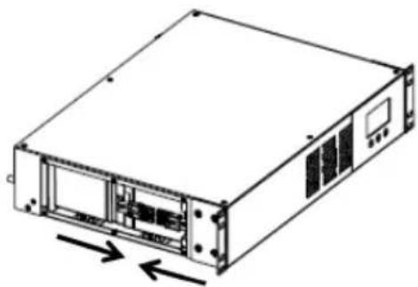
natural_image
Line drawing of a server rack unit with ventilation slots and drive bays (no text or symbols)Figure 10
natural_image
Line drawing of a rectangular electronic device with mounting holes and ventilation slots (no text or symbols)Figure 11
Caractéristiques :
text_image
Energy ENERGY STARRoHS2
DoE 10 CFR Partie 430
Classe B de la FCC
TUV SUD cTUVus (UL1778)
Lewisville, TX 75067
800.238.7272
www.minutemanups.com
34000579 RevC 202510