
MMO17S12ASTC - Microwave Oven MIDEA - Free user manual and instructions
Find the device manual for free MMO17S12ASTC MIDEA in PDF.

| Product Type | Over-the-Range Microwave |
| Brand | MIDEA |
| Model | MMO17S12ASTC |
| Rated Voltage | 120 VAC, 60 Hz |
| Input Power (Microwave) | 1500 W |
| Output Power (Microwave) | 1000 W |
| Product Weight | 28.5 to 38.5 kg (63-85 lbs) |
| Power Supply | 3-prong grounded plug, dedicated 15-20 A circuit |
| Control Panel | Digital keypad, LED display |
| Power Levels | 10 levels (from HI to 10%) |
| Main Functions | Microwave, weight and time defrost, auto cook (bacon, plate, rice, breakfast, pizza), popcorn, potatoes, vegetables, snack menus (hot dogs, frozen meals, mug meals, soup), melt/soften (butter, chocolate, ice cream, cheese) |
| Additional Functions | Quick cook (1-6 number keys or +30 sec), multi-stage cooking, kitchen timer, clock, child lock, demo mode |
| Fan | 2 speeds (High/Low/Off) |
| Lighting | On/Off control |
| Safety | Child lock, auto shut-off, locked door, mandatory grounding |
| Installation | Under-cabinet mounting, external exhaust (vertical/horizontal) or recirculation, requires at least one wall stud |
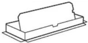
| Included Accessories | Glass turntable, turntable ring, grease filters (x2), exhaust adapter, charcoal filter (depending on model), mounting template, screws and bolts |
| Maintenance | Clean interior with mild non-abrasive soap. Grease filters are washable. Charcoal filter replaceable (every 6-12 months) |
| Repairability | Contact a qualified technician. Midea authorized service center. One-year limited warranty |
| General Information | PDF manual downloadable. Warranty extension possible under conditions. Clean bottom of door and sealing surfaces regularly |
Frequently Asked Questions - MMO17S12ASTC MIDEA
User questions about MMO17S12ASTC MIDEA
0 question about this device. Answer the ones you know or ask your own.
Ask a new question about this device
Download the instructions for your Microwave Oven in PDF format for free! Find your manual MMO17S12ASTC - MIDEA and take your electronic device back in hand. On this page are published all the documents necessary for the use of your device. MMO17S12ASTC by MIDEA.
USER MANUAL MMO17S12ASTC MIDEA
natural_image
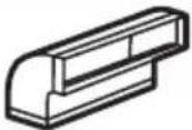
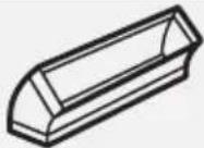
Simple line drawing of a microwave oven with a handle and lid (no text or symbols)Free 3 months
extension of the
original limited warranty
period!* Simply text a
picture of your proof of
purchase to:
1-844-224-1614
*The warranty extension is for the three months
immediately following
the completion of the product's original warranty
period. Individuals do not need to register the
product in order to get all the rights and remedies
of registered owners under the original limited
warranty.
MICROWAVE OVEN
USER MANUAL
MMO17S12ASTC
THANK YOU LETTER
Thank you for choosing Midea! Before using your new Midea product, please read this manual thoroughly to ensure that you know how to operate the features and functions that your new appliance offers in a safe way.
CONTENTS
THANK YOU LETTER EN-01
SAFETY INSTRUCTIONS EN-02
SPECIFICATION EN-11
PRODUCT OVERVIEW EN-12
PRODUCT INSTALLATION EN-13
OPERATION INSTRUCTIONS EN-51
TROUBLESHOOTING EN-61
TRADEMARKS, COPYRIGHTS AND LEGAL STATEMENT --- EN-62
DATA PROTECTION NOTICE EN-63
1YEAR LIMITED WARRANTY EN-64
SAFETY INSTRUCTIONS
Intended Use
The following safety guidelines are intended to prevent unforeseen risks or damage from unsafe or incorrect operation of the appliance. Please check the packaging and appliance on arrival to make sure everything is intact to ensure safe operation. If you find any damage, please contact the retailer or dealer. Please note modifications or alterations to the appliance are not allowed for your safety concern. Unintended use may cause hazards and loss of warranty claims.
Explanation of Symbols
 | DangerThis symbol indicates that there are dangers to the life and health of persons due to extremely flammable gas. |
 | Warning of electrical voltageThis symbol indicates that there is a danger to life and health of persons due to voltage. |
 | WarningThe signal word indicates a hazard with a medium level of risk which, if not avoided, may result in death or serious injury. |
 | CautionThe signal word indicates a hazard with a low degree of risk which, if not avoided, may result in minor or moderate injury. |
 | AttentionThe signal word indicates important information (e.g. damage to property), but not danger. |
 | Observe instructionsThis symbol indicates that a service technician should only operate and maintain this appliance in accordance with the operating instructions. |
Read these operating instructions carefully and attentively before using/commissioning the unit and keep them in the immediate vicinity of the installation site or unit for later use!
PRECAUTIONS TO AVOID POSSIBLE EXPOSURE TO EXCESSIVE MICROWAVE ENERGY
a. Do not attempt to operate this oven with the door open since open door operation can result in harmful exposure to microwave energy. It is important not to defeat or tamper with the safety interlocks.
b. Do not place any object between the oven front face and the door or allows soil or cleaner residue to accumulate on sealing surfaces.
c. Do not operate the oven if it is damaged. It is particularly important that the oven door close properly and that there is no damage to the:
- DOOR (bent)
- HINGES AND LATCHES (broken or loosened)
- DOOR SEALS AND SEALING SURFACES
d. The oven should not be adjusted or repaired by anyone except properly qualified service personnel.
IMPORTANT SAFETY INSTRUCTIONS
When using electrical appliances basic safety precautions should be followed, including the following:
WARNING
To reduce the risk of burns, electric shock, fire, injury to persons or exposure to excessive microwave energy:
- Read all instructions before using the appliance.
- Read and follow the specific: "PRECAUTIONS TO AVOID POSSIBLE EXPOSURE TO EXCESSIVE MICROWAVE ENERGY" found on page 3.
- This appliance must be grounded. Connect only to properly grounded outlet. See "GROUNDING INSTRUCTIONS" found on page 7.
• Install or locate this appliance only in accordance with the provided installation instructions. - Some products such as whole eggs and sealed containers - for example, closed glass jars - are able to explode and should not be heated in this oven.
- Use this appliance only for its intended use as described in the manual. Do not use corrosive chemicals or vapors in this appliance. This type of oven is specifically designed to heat, cook or dry food. It is not designed for industrial or laboratory use.
- HOT CONTENTS CAN CAUSE SEVERE BURNS. DO NOT ALLOW CHILDREN TO USE THE MICROWAVE. Use caution when removing hot items.
-
Do not operate this appliance if it has a damaged cord or plug, if it is not working properly, or if it has been damaged or dropped.
-
This appliance should be serviced only by qualified service personnel. Contact nearest authorized service facility for examination, repair, or adjustment.
- Do not cover or block any openings on the appliance.
- Do not store this appliance outdoors. Do not use this product near water - for example, near a kitchen sink, in a wet basement, near a swimming pool, or similar location.
- Do not immerse cord or plug in water.
- Keep cord away from heated surface.
- Do not let cord hang over edge of table or counter.
- When cleaning surfaces of door and oven that comes together on closing the door, use only mild, nonabrasive soaps, or detergent applied with a sponge or soft cloth.
- To reduce the risk of fire in the oven cavity:
- Do not overcook food. Carefully attend appliance when paper, plastic, or other combustible materials are placed inside the oven to facilitate cooking.
- Remove wire twist-ties from paper or plastic bag before placing bag in oven.
- If material inside of the oven ignite, keep oven door closed, turn oven off, and disconnect the power cord, or shut off power at the fuse or circuit breaker panel.
- Do not use the cavity for storage purposes. Do not leave paper products, cooking utensils, or food in the cavity when not in use.
- Liquids, such as water, coffee, or tea are able to be overheated beyond the boiling point without appearing to be boiling. Visible bubbling or boiling when the container is removed from the microwave oven is not always present.
THIS COULD RESULT IN VERY HOT LIQUID SUDDENLY BOILING OVER WHEN THE CONTAINER IS DISTURBED OR A UTENSIL IS INSERTED INTO THE LIQUID. To reduce the risk of injury to persons:
- Do not overheat the liquid.
- Stir the liquid both before and halfway through heating it.
- Do not use straight-sided containers with narrow necks.
- After heating, allow the container to stand in the microwave oven for a short time before removing the container.
- Use extreme care when inserting a spoon or other utensil into the container.
- Oversized food or oversized metal utensils should not be inserted in a microwave/toaster oven as they may create a fire or risk of electric shock.
- Do not clean with metal scouring pads. Pieces can burn off the pad and touch electrical parts involving a risk of electric shock.
- Do not use paper products when appliance is operated in the toaster mode.
- Do not store any materials, other than manufacturer's recommended accessories, in this oven when not in use.
- Do not cover racks or any other part of the oven with metal foil. This will cause overheating of the oven.
- Clean Ventilation Hoods Frequently - Grease should not be allowed to accumulate on hood or filter.
- When flaming foods under the hood, turn the fan on.
- Use care when cleaning the vent-hood filter. Corrosive cleaning agents, such as lyebased oven cleaners, may damage the filter.
- Suitable for use above both gas and electric cooking equipment.
SAVE THESE INSTRUCTIONS
GROUNDING INSTRUCTIONS
This appliance must be grounded. In the event of an electrical short circuit, grounding reduces the risk of electric shock by providing an escape wire for the electric current. This appliance is equipped with a cord having a grounding wire with a grounding plug. The plug must be plugged into an outlet that is properly installed and grounded.
WARNING
Improper use of the grounding can result in a risk of electric shock. Consult a qualified electrician or serviceman if the grounding instructions are not completely understood, or if doubt exists as to whether the appliance is properly grounded. If it is necessary to use an extension cord, use only a 3-wire extension cord that has a 3-blade grounded plug, and 3-slot receptacle that will accept the plug on the appliance. The marked rating of the extension cord shall be equal to or greater than the electrical rating of the appliance.
DANGER
Electric Shock Hazard
Touching some of the internal components can cause serious personal injury or death. Do not disassemble this appliance.
WARNING
Electric Shock Hazard
Improper use of the grounding can result in electric shock. Do not plug into an outlet until appliance is properly installed and grounded.
- A short power-supply cord is provided to reduce the risks resulting from becoming entangled in or tripping over a longer cord.
- Longer cord sets or extension cords are available and may be used if care is exercised in their use.
- If a long cord or extension cord is used:
- The marked electrical rating of the cord set or extension cord should be at least as great as the electrical rating of the appliance.
- The extension cord must be a grounding-type 3-wire cord.
- The longer cord should be arranged so that it will not drape over the counter top or tabletop where it can be pulled on by children or tripped over unintentionally.
RADIO INTERFERENCE
- Operation of the microwave oven may cause interference to your radio, TV or similar equipment.
- When there is interference, it may be reduced or eliminated by taking the following measures:
- Clean door and sealing surface of the oven
- Reorient the receiving antenna of radio or television.
- Relocate the microwave oven with respect to the receiver.
- Move the microwave oven away from the receiver.
- Plug the microwave oven into a different outlet so that microwave oven and receiver are on different branch circuits.
THIS DEVICE COMPLIES WITH PART 18 OF THE FCC RULES.
UTENSILS

CAUTION
Personal Injury Hazard
Tightly-closed utensils could explode. Closed containers should be opened and plastic pouches should be pierced before cooking.
See the instructions on "Materials you can use in microwave oven or to be avoided in microwave oven." There may be certain non-metallic utensils that are not safe to use for microwaving. If in doubt, you can test the utensil in question following the procedure below.
Utensil Test:
- Fill a microwave-safe container with 1 cup of cold water (250ml) along with the utensil in question.
- Cook on maximum power for 1 minute.
- Carefully feel the utensil. If the empty utensil is warm, do not use it for microwave cooking.
- Do not exceed 1 minute cooking time.
Materials you can use in microwave oven
| Utensils Remarks | |
| Browning dish | Follow manufacturer's instructions. The bottom of browning dish must be at least 3/16 inch (5mm) above the turntable. Incorrect usage may cause the turntable to break. |
| Dinnerware | Microwave-safe only. Follow manufacturer's instructions. Do not use cracked or chipped dishes. |
| Glass jars | Always remove lid. Use only to heat food until just warm. Most glass jars are not heat resistant and may break. |
| Glassware | Heat-resistant oven glassware only. Make sure there is no metallic trim. Do not use cracked or chipped dishes. |
| Oven cooking bags | Follow manufacturer's instructions. Do not close with metal tie. Make slits to allow steam to escape. |
| Paper plates and cups | Use for short-term cooking/warming only. Do not leave oven unattended while cooking. |
| Paper towels | Use to cover food for reheating and absorbing fat. Use with supervision for a short-term cooking only. |
| Parchment paper | Use as a cover to prevent splattering or a wrap for steaming. |
| Plastic | Microwave-safe only. Follow the manufacturer's instructions. Should be labeled "Microwave Safe". Some plastic containers soften, as the food inside gets hot. "Boiling bags" and tightly closed plastic bags should be slit, pierced or vented as directed by package. |
| Plastic wrap | Microwave-safe only. Use to cover food during cooking to retain moisture. Do not allow plastic wrap to touch food. |
| Thermometers Microwave-safe only (meat and candy thermometers). | |
| Wax paper Use as a cover to prevent splattering and retain moisture. | |
Materials to be avoided in microwave oven
| Utensils Remarks | |
| Aluminum tray | May cause arcing. Transfer food into microwave-safe dish. |
| Food carton with metal handle | May cause arcing. Transfer food into microwave-safe dish. |
| Metal or metal-trimmed utensils | Metal shields the food from microwave energy. Metal trim may cause arcing. |
| Metal twist ties May cause arcing and could cause a fire in the oven. | |
| Paper bags May cause a fire in the oven. | |
| Plastic foam | Plastic foam may melt or contaminate the liquid inside when exposed to high temperature. |
| Wood | Wood will dry out when used in the microwave oven and may split or crack. |
SPECIFICATION
| MODEL | MMO17S12ASTC |
| Rated Voltage/Frequency | 120VAC 60Hz |
| Rated Input(Microwave) | 1500 W |
| Rated Output(Microwave) | 1000 W |
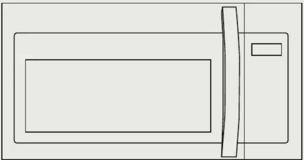
PRODUCT OVERVIEW
Setting Up Your Oven
PART NAMES
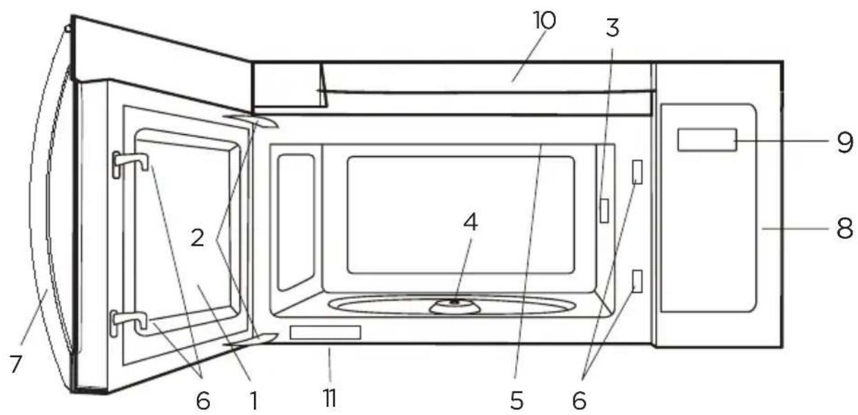
- Microwave oven door with see-through window
- Door hinges
- Waveguide cover: DO NOT REMOVE.
- Turntable motor shaft
- Microwave oven light
It will light when microwave oven is operating or door is open. - Safety door latches
The microwave oven will not operate unless the door is securely closed. - Handle
- Control panel
- Display
- Ventilation openings
- Rating label
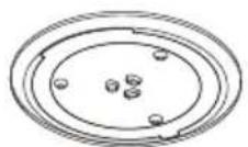
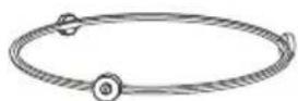
Glass turntable Turntable Ring Assembly
PRODUCT INSTALLATION
Important Safety Instructions
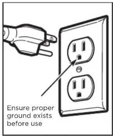
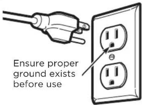
This product requires a three-prong grounded outlet. The installer must perform a ground continuity check on the power outlet box before beginning the installation to ensure that the outlet box is properly grounded. If not properly grounded, or if the outlet box does not meet electrical requirements noted (under ELECTRICAL REQUIREMENTS), a qualified electrician should be employed to correct any deficiencies.

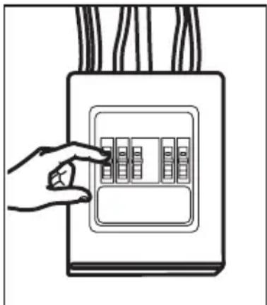
CAUTION:
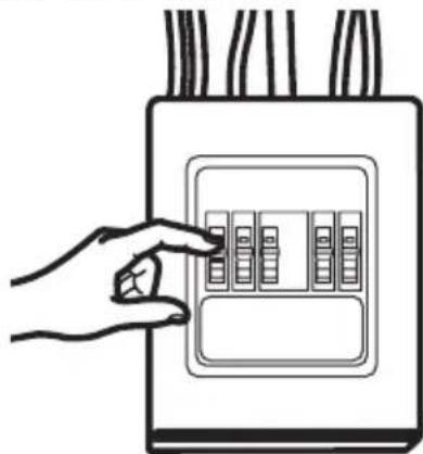
For personal safety, remove house fuse or open circuit breaker before beginning installation to avoid severe or fatal shock injury.
natural_image
Line drawing of a hand inserting a component into an electrical outlet (no text or symbols)
CAUTION:
For personal safety, the mounting surface must be capable of supporting the cabinet load, in addition to the added weight of this 63-85 pound (28.5-38.5 kg) product, plus additional oven loads of up to 50 pounds (22.7 kg) or a total weight of 113-135 pounds (51.3-61.2 kg).

CAUTION:
For personal safety, this product cannot be installed in cabinet arrangements such as an island or a peninsula. It must be mounted to BOTH a top cabinet AND a wall.

NOTE:
For easier installation and personal safety, it is recommended that two people install this product.
IMPORTANT - PLEASE READ CAREFULLY. FOR PERSONAL SAFETY, THIS APPLIANCE MUST BE PROPERLY GROUNDED TO AVOID SEVERE OR FATAL SHOCK.
The power cord of this appliance is equipped with a three-prong (grounding) plug which mates with a standard three-prong (grounding) wall receptacle to minimize the possibility of electric shock hazard from this appliance.
You should have the wall receptacle and circuit checked by a qualified electrician to make sure the receptacle is properly grounded.
Where a standard two-prong wall receptacle is encountered, it is very important to have it replaced with a properly grounded three-prong wall receptacle, installed by a qualified electrician.
DO NOT, UNDER ANY CIRCUMSTANCES, CUT, DEFORM OR REMOVE ANY OF THE PRONGS FROM THE POWER CORD. DO NOT USE WITH AN EXTENSION CORD.
Electrical Requirements
Product rating is 120 volts AC, 60 Hertz, 15 amps and 1.55 kilowatts. This product must be connected to a separate and dedicated supply circuit of the proper voltage and frequency. Wire size must conform to the requirements of the National Electrical Code or the prevailing local code for this kilowatt rating. The power supply cord and plug should be brought to a separate and dedicated 20 ampere branch circuit single grounded outlet. The outlet box should be located in the cabinet above the microwave oven. The outlier box and supply circuit should be installed by a qualified electrician and conform to the National Electrical Code or the prevailing local code.
Damage—Shipment/Installation
- If the unit is damaged in shipment, return the unit to the store in which it was bought for repair or replacement.
- If the unit is damaged by the customer, repair or replacement is the responsibility of the customer.
- If the unit is damaged by the installer (if other than the customer), repair or replacement must be made by arrangement between customer and installer.
Parts Included
HARDWARE PACKET
| PART QUANTITY | ||
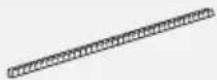
 | Wood Screws (1/4" x 2") 2 | |
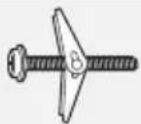 | Toggle Bolts (and wing nuts) (3/16" x 3") | 2 |
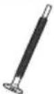 | Self-Aligning Machine Screws (1/4"-28 x 31/4") | 3 |
 | Nylon Grommet (for metal cabinets) | 1 |
You will find the installation hardware contained in a packet with the unit. Check to make sure you have all these parts.

NOTE:
Some extra parts are included.
ADDITIONAL PARTS
| PART QUANTITY | ||
 | Top Cabinet Template 1 | |
 | Rear Wall Template 1 | |
 | User Manual | 1 |
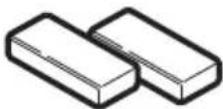
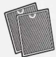 | Separately Packed Grease Filters 2 | |
 | Exhaust adaptor 1 | |
 | Glass Tray 1 | |
 | Turntable Ring 1 | |
For some models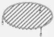 | Convection wire rack 1 | |
For some models | Shelf 1 | |
For some models | PureAir®Microwave Filter 1 | |
Tools You Will Need
1 Phillips screwdriver
Pencil
Tin snips (for cutting damper, if required)
Scissors (to cut template, if necessary)

natural_image
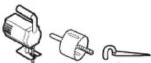
Technical line drawing of a drill bit with screwdriver and other components (no text or labels)Electric drill with 316 , 12 and 58 drill bits
Filler blocks or scrap wood pieces, if needed for top cabinet spacing (used on recessed bottom cabinet installations only)
Gloves
natural_image
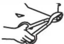
Technical line drawing of three mechanical components: a pump, a motor, and a hook (no text or symbols)Saw (saber, hole or keyhole)

Stud finder or Hammer (optional)
Safety goggles
Level
Duct and masking tape
MOUNTING SPACE

NOTE:
- The space between the cabinets must be 30" (76.2 cm) wide and free of obstructions.
- If you are going to vent your microwave oven to the outside, see Hood Exhaust Section for exhaust duct preparation.
- When installing the microwave oven beneath smooth, flat cabinets, be careful to follow the instructions on the top cabinet template for power cord clearance.
• As a guide to installation, see page 25 for Mounting Template Information.
1. Placement Of The Mounting Plate
A. REMOVING THE MICROWAVE OVEN FROM THE CARTON/REMOVING THE MOUNTING PLATE
- Remove the top cover board, installation instructions, use and care, exhaust adapter, turntable ring, shelf, filters, glass tray and the small hardwarebag. Do not remove the Styrofoam protecting the front of the oven.

Filters and Turntable Ring below glass tray
- Fold back all 4 carton flaps fully against carton sides. Then carefully roll the oven and carton over onto the top side. The oven should be resting in the Styrofoam.
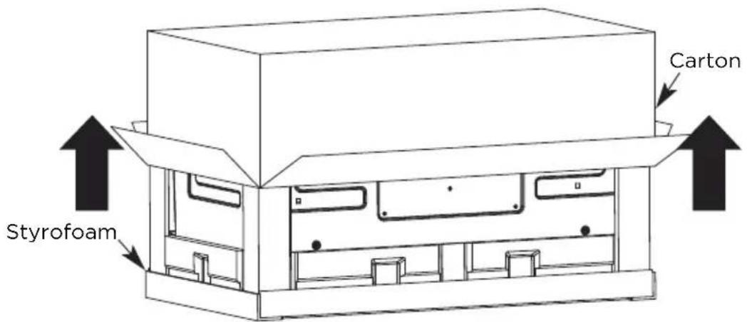
-
Pull the carton up and off the oven.
-
Cut the middle of the outer protective plastic bag to remove the mounting plate

- Remove the screws from each end of the mounting plate. This plate will be used as the rear wall template and for mounting. Reinstall the screws into the holes where they were removed.
B. FINDING THE WALL STUDS
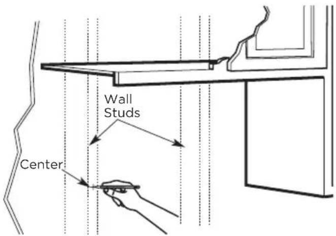
- Find the studs, using one of the following methods:
- Stud finder - a magnetic device which locates nails.
- Use a hammer to tap lightly across the mounting surface to find a solid sound. This will indicate a stud location.
- After locating the stud(s), find the center by
probing the wall with a small nail to find the edges of the stud. Then place a mark halfway between the edges. The center of any adjacent studs should be 16" (40.6 cm) or 24" (61 cm) from this mark.
- Draw a line down the center of the studs.
THE MICROWAVE MUST BE CONNECTED TO AT LEAST ONE WALL STUD.
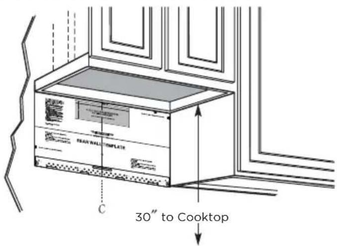
C. DETERMINING WALL PLATE LOCATION UNDER YOUR CABINET
Plate position-beneath flat bottom cabinet
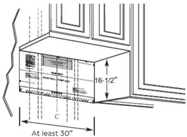
Draw a vertical line on the wall at the center of the 30" wide space.
Tape the Rear Wall Template onto the wall matching the centerline and touching the bottom of the cabinet.
Plate position-beneath recessed bottom cabinet with front overhang
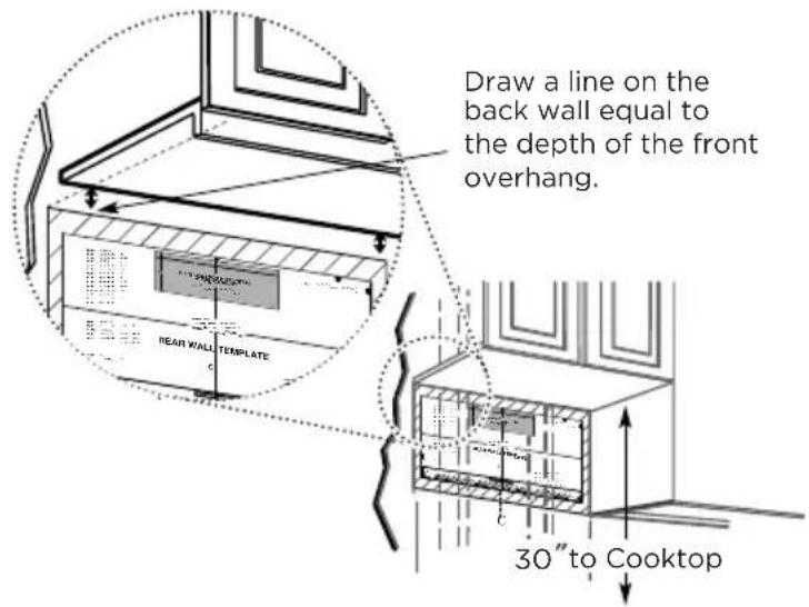
Plate position-beneath framed recessed cabinet bottom
Draw a vertical line on the wall at the center of the 30" space.
Tape the Rear Wall Template onto the wall matching the centerline and touching the bottom cabinet frame.
Your cabinets may have decorative trim that interferes with the microwave installation. Remove the decorative trim to install the microwave properly and to make it level.
Use a level to make sure the cabinet bottom is level.
If the cabinets have a front overhang only, with no back or side frame, install the mounting plate down the same distance as the front overhang depth. This will keep the microwave level.
- Measure the inside depth of the front overhang.
- Draw a horizontal line on the back wall an equal distance below the cabinet bottom as the inside depth of the front overhang.
- For this type of installation with front overhang only, align the mounting tabs with this horizontal line, not touching the cabinet bottom as described in Step D.
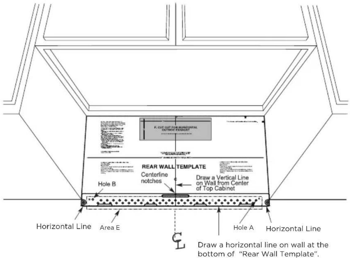
D. ALIGNING THE WALL PLATE

CAUTION:
Wear gloves to avoid cutting fingers on sharp edges.
- Draw a vertical line on the wall at the center of the 30" wide space.
- Draw a horizontal line on the wall at the bottom of "Rear Wall Template".
- Find a wall stud in area "E" of mounting plate Refer to section 1B. Finding the wall studs.
- For attaching the mounting plate into stud drill a 3/16" hole into wood stud. Drill a 5/8" hole for toggle bolt in 1 other location (Hole A or Hole B)

NOTE:
DO NOT MOUNT THE PLATE AT THIS TIME.

NOTE:
Holes A and B are inside area E. If neither of Holes A and B are not in a stud, find a stud somewhere in area E and draw a circle to line up with the stud. It is important to have at least one wood screw mounted firmly in a stud to support the weight of the microwave. Set the mounting plate aside.
2. Installation Types (Choose A, B or C)
This microwave oven is designed for adaptation to the following three types of ventilation:
A. Outside Top Exhaust (Vertical Duct)
B. Outside Back Exhaust (Horizontal Duct)
C. Recirculating (Non-Vented Ductless)

NOTE:
This microwave is shipped assembled for Recirculating. Select the type of ventilation required for your installation and proceed to that section.
A. OUTSIDE TOP EXHAUST (VERTICAL DUCT)
B. OUTSIDE BACK EXHAUST (HORIZONTAL DUCT)
C. RECIRCULATING (NON-VENTED DUCTLESS)

natural_image
Line drawing of a microwave oven with internal compartments and a black arrow indicating upward motion (no text or symbols)See page 41
Models are shipped for recirculating exhaust. Some models have a disposable charcoal filter installed to help remove smoke and odors.

NOTE:
Read the next two pages only if you plan to vent your exhaust to the outside. If you plan to recirculate the air back into the room, proceed to page 23-26.
Installation Instructions For External Exhaust Ducting

NOTE:
If you need to install ducts, note that the total duct length of 3^1/4 x 10" (8.2 x 25.4 cm) rectangular or 5" (12.7 cm) diameter/6" " (15.2 cm) diameter round duct should not exceed 120 equivalent feet (36.5 m).
Outside ventilation requires an EXTERNAL EXHAUST DUCT.Read the following carefully.

NOTE:
It is important that venting be installed using the most direct route and with as few elbows as possible. This ensures clear venting of exhaust and helps prevent blockages. Also, make sure dampers swing freely and nothing is blocking the ducts.
Exhaust connection:
The exhaust adaptor has been designed to mate with a standard 3^1/_4 " x 10" (8.2 x 25.4 cm) rectangular duct.
If a round duct is required, a rectangular-to-round transition adaptor must be used. A5" (12.7cm)/6" (15.2cm) diameter duct is acceptable to use.
Maximum duct length:
For satisfactory air movement, the total duct length of 3^1/_4 " x 10" (8.2 x 25.4 cm) rectangular or 5" (12.7 cm) diameter/6"(15.2 cm) diameter round duct should not exceed 120 equivalent feet (36.5 m).
Elbows, transitions, wall and roof caps, etc., present additional resistance to airflow and are equivalent to a section of straight duct which is longer than their actual physical size. When calculating the total duct length, add the equivalent lengths of all transitions and adaptors plus the length of all straight duct sections. The chart below shows you how
to calculate total equivalent ductwork length using the approximate feet of equivalent length of some typical ducts.
| DUCT PIECES | EQUIVALENT LENGTH | x | NUMBER USED | = | EQUIVALENT LENGTH | |
 | Rectangular-to-Round Transition Adaptor* | 5 Ft. (1.5 m) x ( ) = Ft. or m | ||||
 | Wall Cap 40 Ft. (12.2 m) x ( ) = Ft. or m | |||||
 | 90° Elbow 10 Ft. (3 m) x ( ) = Ft. or m | |||||
 | 45° Elbow 5 Ft. (1.5 m) x ( ) = Ft. or m | |||||
 | 90° Elbow 25 Ft. (7.6 m) x ( ) = Ft. or m | |||||
 | 45° Elbow 5 Ft. (1.5 m) x ( ) = Ft. or m | |||||
 | Roof Cap 24 Ft. (7.3 m) x ( ) = Ft. or m | |||||
 | Straight Duct 6" (15.2 cm) Round or 3^1/_4'' × 10'' (8.2 x 25.4 cm Rectangular) | 1 Ft. (0.3 m) x ( ) = Ft. or m | ||||
| Total Ductwork = Ft. or m | ||||||
* IMPORTANT: If a rectangular-to-round transition adaptor is used, the bottom corners of the damper will have to be cut to fit, using the tin snips, in order to allow free movement of the damper.
Equivalent lengths of duct pieces are based on actual tests and reflect requirements for good venting performance with any vent hood.
External Exhaust Ducting
OUTSIDE TOP EXHAUST (EXAMPLE ONLY)
The following chart describes an example of one possible ductwork installation.
| DUCT PIECES | EQUIVALENT LENGTH | x | NUMBER USED | = | EQUIVALENT LENGTH | |
 | Roof Cap 24 Ft. (7.3 m) x (1) = 24 Ft. (7.3 m) | |||||
 | 12 Ft. (3.6 m) Straight Duct (6"/15.2 cm Round) | 12 Ft. (3.6 m) x (1) = 12 Ft. (3.6 m) | ||||
| [2530] | Rectangular-to-Round Transition Adaptor* | 5 Ft. (1.5 m) x (1) = 5 Ft. (1.5 m) | ||||
| Equivalent lengths of duct pieces are based on actual tests and reflect requirements for good venting performance with any vent hood. | Total Length = 41 Ft. (12.5 m) | |||||
natural_image
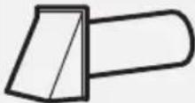
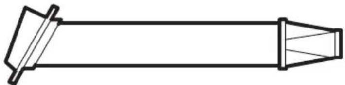
Simple line drawing of a conical object with two protruding flanges (no text or symbols)* IMPORTANT: If a rectangular-to-round transition adaptor is used, the bottom corners of the damper will have to be cut to fit, using the tin snips, in order to allow free movement of the damper.
OUTSIDE BACK EXHAUST (EXAMPLE ONLY)
The following chart describes an example of one possible ductwork installation.
| DUCT PIECES | EQUIVALENT LENGTH | x | NUMBER USED | = | EQUIVALENT LENGTH | |
 | Wall Cap 40 Ft. (12.2 m) x (1) = 40 Ft. (12.2 m) | |||||
 | 3 Ft. Straight Duct ( 314% × 10% /8.2. x 25.4 cm Rectangular) | 3 Ft. (0.9 m) | x (1) = 3 Ft. (0.9 m) | |||
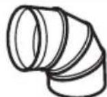
Equivalent lengths of duct pieces are based on actual tests and reflect requirements for good venting performance with any vent hood.
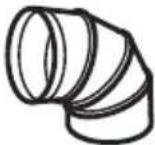
90^ Elbow 10 Ft. (3 m) x (2) = 20 Ft. (3 m)
Total Length = 63 Ft. (19.2 m)
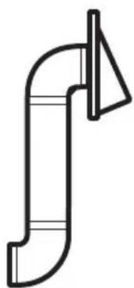
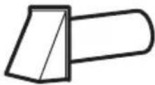
natural_image
Pure line drawing of a curved pipe or duct with a triangular support at the end (no text or symbols)
NOTE:
For back exhaust, care should be taken to align exhaust with space between studs, or wall should be prepared at the time it is constructed by leaving enough space between the wall studs to accommodate exhaust.
A. OUTSIDE TOP EXHAUST (Vertical Duct)
INSTALLATION OVERVIEW
A1. Attach Mounting Plate to wall
A2. Prepare Top Cabinet
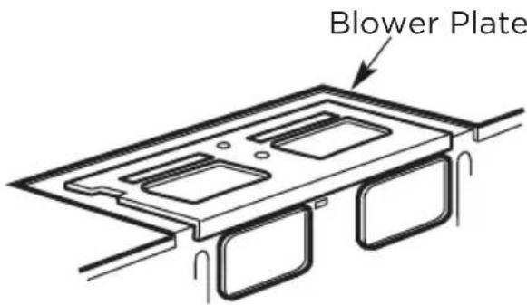
A3. Configure Microwave Blower for Outside / Top Exhaust
A4. Check Damper Operation
A5. Mount Microwave Oven
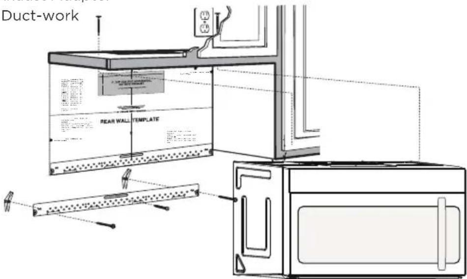
A6. Adjust Exhaust Adapter
A7. Connect Duct-work
IMPORTANT NOTES:
- Make sure the screws for the Blower Motor and Blower Plate are securely tight-ended when they are installed. This will help to prevent excessive vibration.
- Make sure the Motor wiring has been properly routed and secured, and that the wires are not pinched.
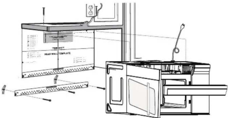
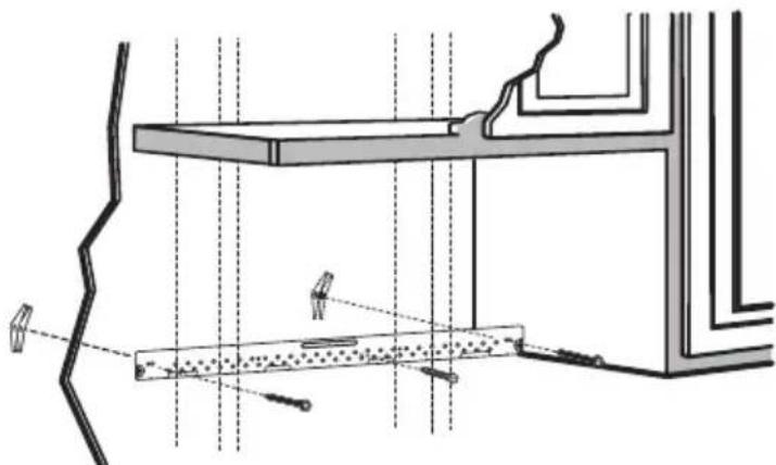
A1. ATTACH THE MOUNTING PLATE TO THE WALL
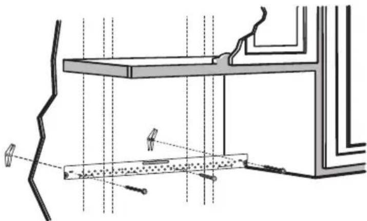
natural_image
Architectural cross-section diagram showing structural layers and window connections (no text or labels)- Attach the plate to the wall using toggle bolts.
- At least one wood screw must be used to attach the plate to a wall stud.
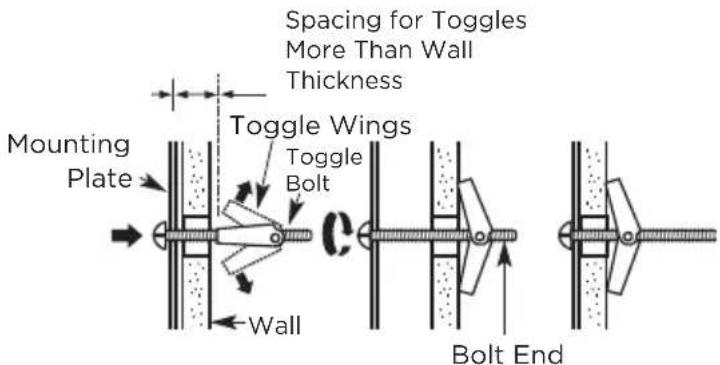
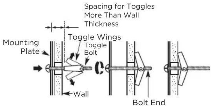
- Remove the toggle wings from the bolts
- Insert the bolts into the mounting plate through the holes designated to go into drywall and reattach the toggle wings to 3/4" (19mm) onto each bolt.
To use toggle bolts:
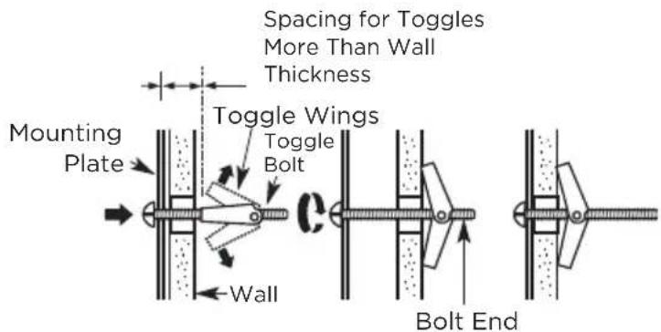
- Place the mounting plate against the wall and insert the toggle wings into the holes in the wall to mount the plate.

NOTE:
Before tightening toggle bolts and wood screw, make sure the bottom of the mounting plate touches the bottom of the cabinet when pushed flush against the wall and the plate is properly centered under the cabinet.

CAUTION:
Be careful and avoid pinching fingers between the back of the mounting plate and the wall.
- Tighten all bolts. Pull the plate away from the wall to help tighten the bolts.
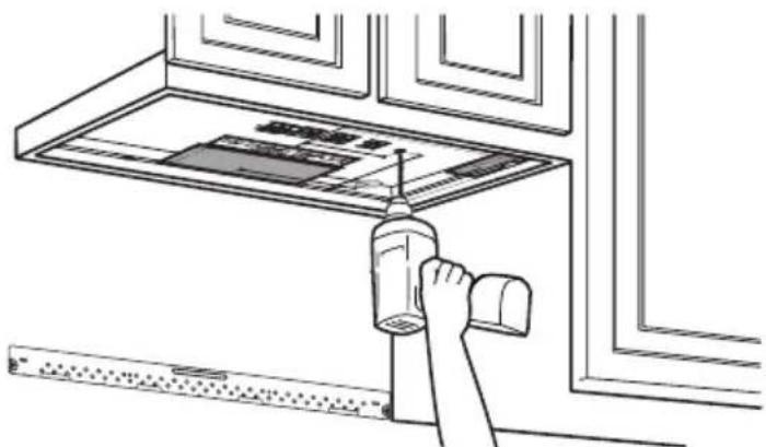
A2. USE TOP CABINET TEMPLATE FOR PREPARATION OF TOP CABINET
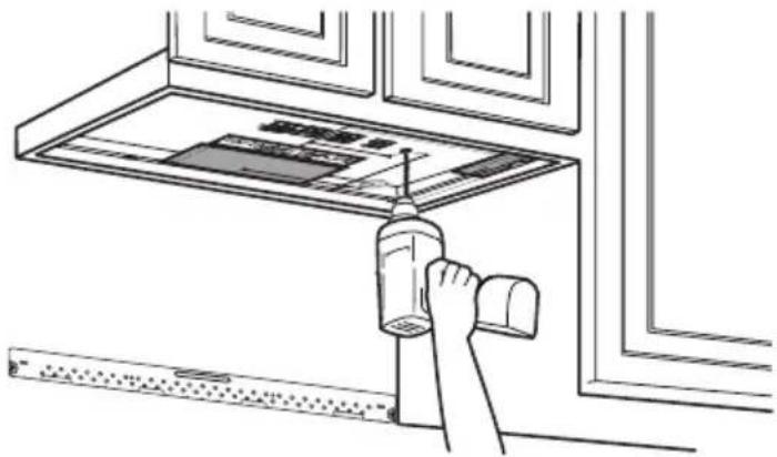
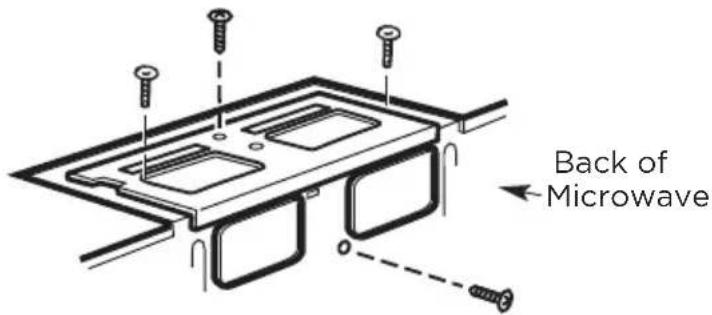
You need to drill holes for the top support screws, a hole large enough for the power cord to fit through, and a cutout large enough for the exhaust adaptor.
natural_image
Line drawing of a hand cleaning a window with a spray bottle (no text or symbols)- Read the instructions on the TOP CABINET TEMPLATE.
- Tape it underneath the top cabinet.
- Drill the holes, following the instructions on the TOP CABINET TEMPLATE.

CAUTION:
Wear safety goggles when drilling holes in the cabinet bottom.
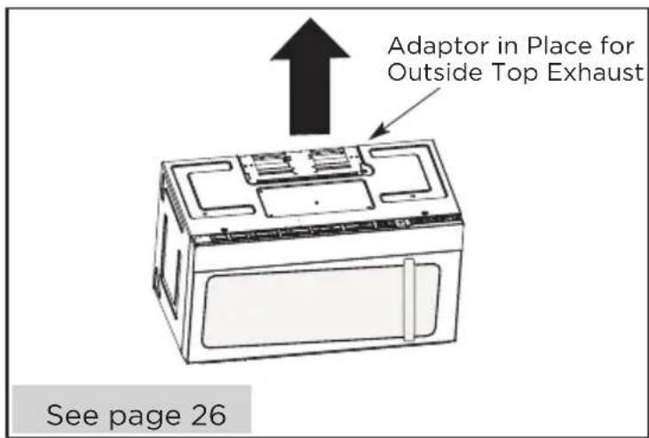
A3. ADAPTING MICROWA VE BLOWER FOR OUTSIDE TOP EXHAUST
- Place the microwave in its upright position, with the top of the unit facing up.
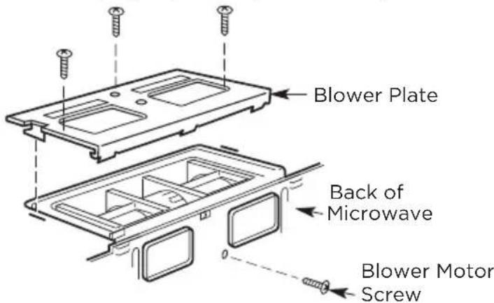
Remove the screw that holds the blower plate to the microwave. Remove and save the screw holding the blower motor to the microwave.
- Carefully pull out the blower unit. The wires will extend far enough to allow you to adjust the blower unit.
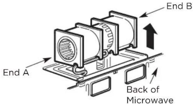
- Roll the blower unit 90^ so that fan blade openings are facing out the top of the microwave.
Before Rotation After Rotation
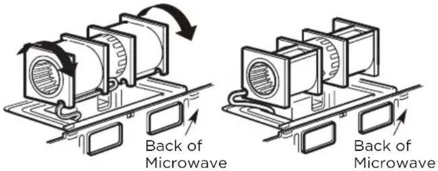
- Place the blower unit back into the opening.
AFTER: Fan Blade
Openings Facing Top


CAUTION:
Do not pull or stretch the blower unit wiring. Make sure the wires are not pinched, and that they are properly secured.
-
Secure blower unit to microwave with the screw removed in Step 1. Make sure the screw is tight.
-
Replace blower plate with the screw removed in Step 1. Make sure the screw is tight.
- Attach the exhaust adaptor to the top of the blower plate by sliding it into the guides of the blower plate.
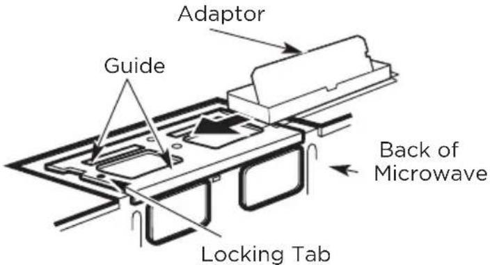
Push in securely until it is in the locking tabs. Take care to assure that the damper hinge is installed so that the damper swings freely.
- Make sure tape securing damper is removed and damper pivots easily before mounting microwave.
- You will need to make adjustments to assure proper alignment with your house exhaust duct after the microwave is installed.
natural_image
Three-panel line drawing showing a person crossed out of a box, another with a cross symbol, and a third holding a box (no text or symbols present)FOR EASIER INSTALLATION AND PERSONAL SAFETY, WE RECOMMEND THAT TWO PEOPLE INSTALL THIS MICROWAVE OVEN.
IMPORTANT: Do not grip or use the handle or heat shield during installation. Do not remove the cardboard spacers between the heat shield and door.

NOTE:
If your cabinet is metal, use the nylon grommet around the power cord hole to prevent cutting of the cord.

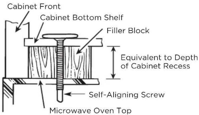
NOTE:
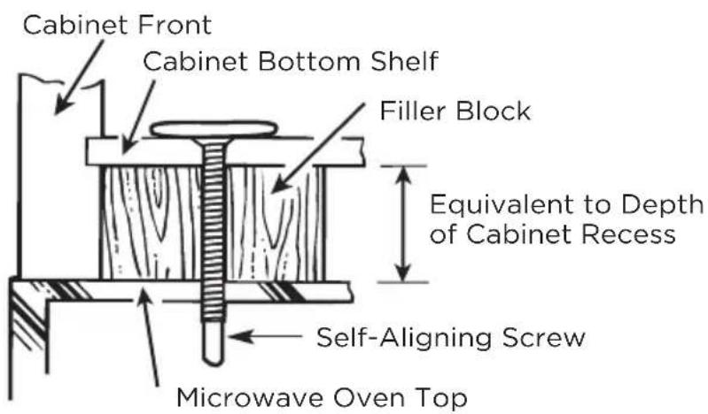
We recommend using filler blocks if the cabinet front hangs below the cabinet bottom shelf.
IMPORTANT: If filler blocks are not used, case damage may occur from overtightening screws.
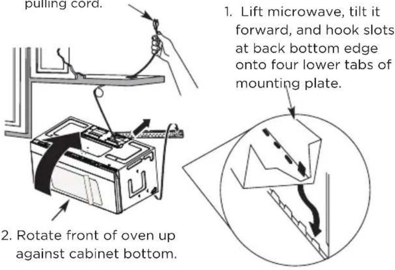
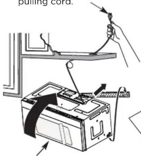
NOTE: When mounting the microwave oven, thread power cord through hole in bottom of top cabinet. Keep it tight throughout steps 1-3. Do not pinch cord or lift oven by pulling cord.
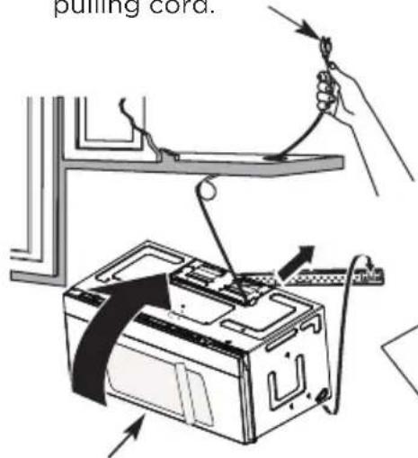
2 Rotate front of oven up against cabinet bottom.
- Lift microwave, tilt it forward, and hook slots at back bottom edge onto four lower tabs of mounting plate.
- Insert a self-aligning screw through top center cabinet hole. Temporarily secure the oven by turning the screw at least two full turns after the threads have engaged. (It will be completely tightened later.) Be sure to keep power cord tight. Be careful not to pinch the cord, especially when mounting flush to bottom of cabinet.

-
Attach the microwave oven to the top cabinet.
-
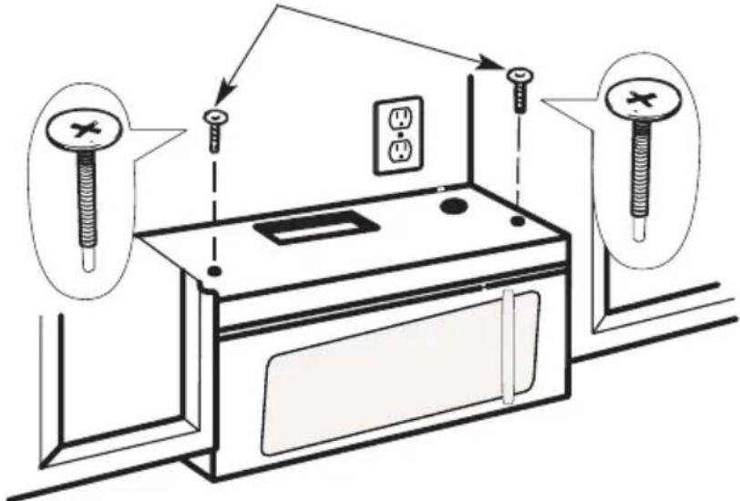
Insert 2 self-aligning screws through outer top cabinet holes. Turn two full turns on each screw.
- Tighten the outer two screws to the top of the microwave oven. (While tightening screws, hold the microwave oven in place against the wall and the top cabinet.)
natural_image
Hand inserting a small rectangular object into a grid-patterned panel (no text or symbols)- Install grease filters. See the Use & Care Guide packed with the microwave.
A6. ADJUST THE EXHAUST ADAPTOR
Open the top cabinet and adjust the exhaust adapter to connect to the house duct.
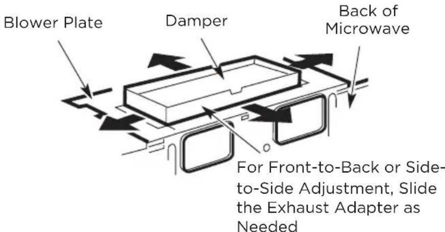
A7. CONNECTING DUCTWORK
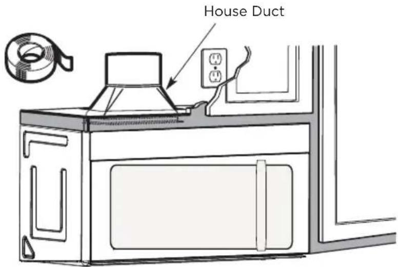
- Extend the house duct down to connect to the exhaust adapter.
- Seal exhaust duct joints using furnace duct tape for high temperature applications
B. OUTSIDE BACK EXHAUST (Horizontal Duct)
INSTALLATION OVERVIEW
B1. Prepare Rear Wall
B2. Remove Blower Plate
B3. Attach Mounting Plate to Wall B4. Prepare Top Cabinet
B5. Adjust Blower
B6. Mount the Microwave Oven
IMPORTANT NOTES:
- Make sure the screws for the blower motor and blower plate are securely tightened when they are reinstalled. This will help pre-vent excessive vibration.
- Make sure the motor wiring has been properly routed and se-cured and that the wires are not pinched.
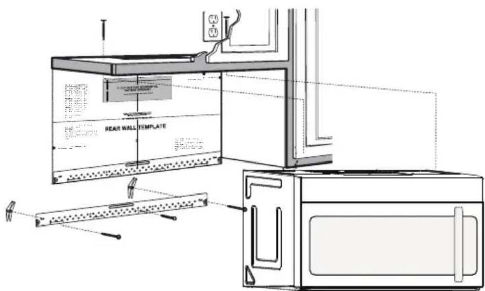
B1. PREPARING THE REAR WALL FOR OUTSIDE BACK EXHAUST
You need to cut an opening in the rear wall for outside exhaust.
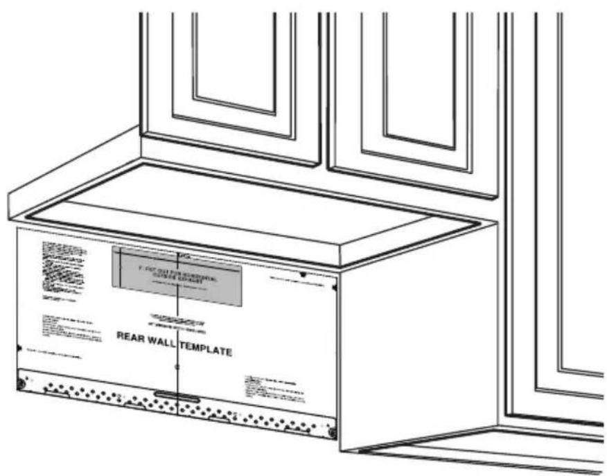
- Read the instructions on the REAR WALL TEMPLATE. Tape it to the rear wall.
- Cut the opening, following the instructions of the
- REAR WALL TEMPLATE.
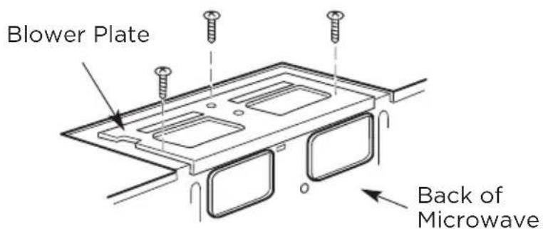
B2. REMOVE BLOWER PLATE
Remove and save the screw that holds the blower plate to the microwave. Lift off the blower plate.
B3. ATTACH THE MOUNTING PLATE TO THE WALL

natural_image
Technical line drawing of a structural assembly with beams, supports, and a beam (no text or symbols)Attach the plate to the wall using toggle bolts. At least one wood screw must be used to attach the plate to a wall stud.
- Remove the toggle wings from the bolts.
- Insert the bolts into the mounting plate through the holes designated to go into drywall and reattach the toggle wings to 3/4" (19 mm) onto each bolt.
To use toggle bolts:
- Place the mounting plate against the wall and insert the toggle wings into the holes in the wall to mount the plate.

NOTE:
Before tightening toggle bolts and wood screw, make sure the bottom of the mounting plate touch the bottom of the cabinet when pushed flush against the wall and that the plate is properly centered under the cabinet.

CAUTION:
Be careful to avoid pinching fingers between the back of the mounting plate and the wall.
- Tighten all bolts. Pull the plate away from the wall to help tighten the bolts.
B4. USE TOP CABINET TEMPLATE FOR PREPARATION OF TOP CABINET
You need to drill holes for the top sup-port screws and a hole large enough for the power cord to fit through.

natural_image
Line drawing of a hand using a tool to clean or store items on a kitchen counter (no text or symbols)- Read the instructions on the TOP CABINET TEMPLATE.
- Tape it underneath the top cabinet.
- Drill the holes, following the instructions on the TOP CABINET TEMPLATE.

CAUTION:
Wear safety goggles when drilling holes in the cabinet bottom.
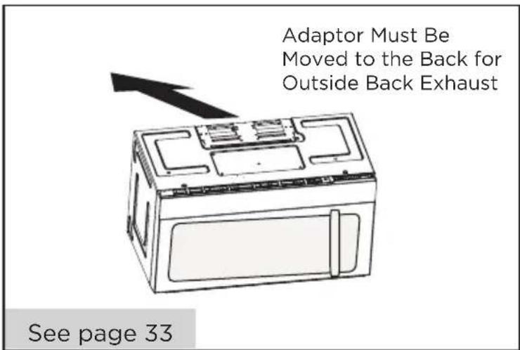
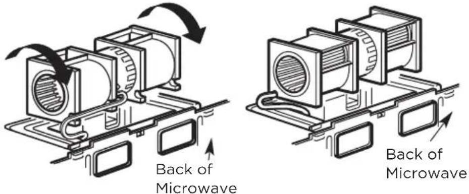
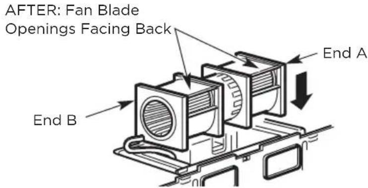
B5. ADAPTING MICROWAVE BLOWER FOR OUTSIDE BACK EXHAUST
- Remove and save screw that holds blower motor to microwave.
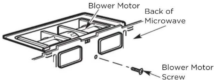
- Carefully pull out the blower unit. The wires will extend far enough to allow you to adjust the blower unit.
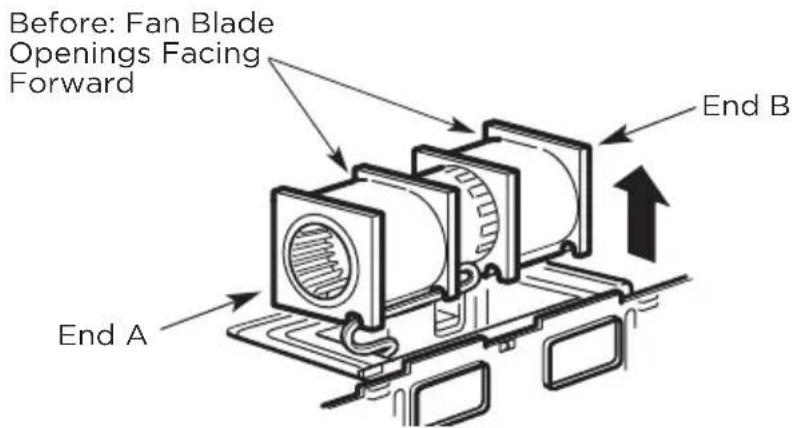
- Roll the blower unit 90°
Before Rotation After Rotation
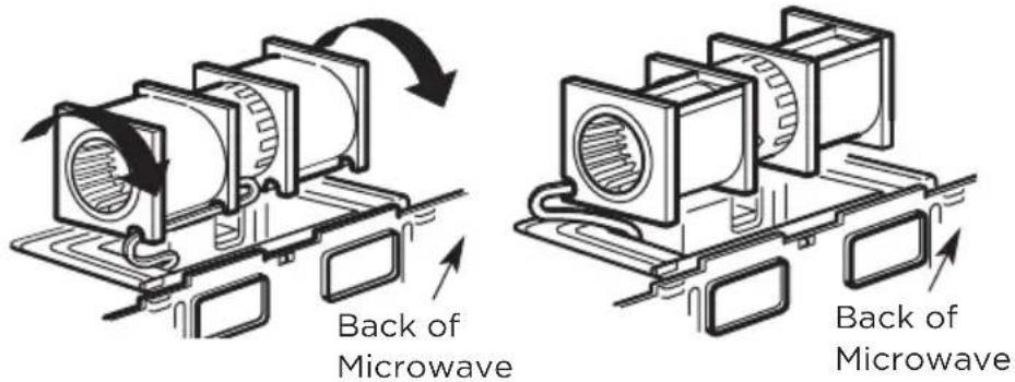
- Rotate blower unit counterclockwise 180°.
Before Rotation After Rotation
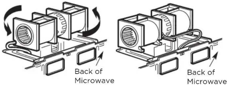
- Gently remove the wires from the grooves. Reroute the wires through grooves on other side of the blower unit.
Before Rerouting After Rerouting
- Rotate the blower unit 90^ so that fan blade openings are facing out the back of the mi-crowave.
Before Rolling After Rolling
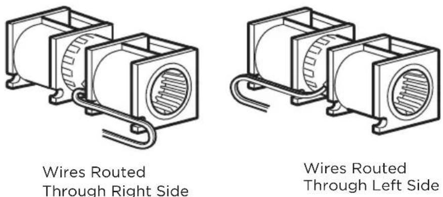
- Remove the knockout plates in the back of the unit with snips. (for some models)
natural_image
Technical line drawing of a vehicle chassis frame with mounting brackets and structural details (no text or symbols)Back of Microwave
Knockout Plates: Snip all 4 webs on each knockout panel and remove the metal knockouts for rear airflow. Please take care to remove any sharp edges created from removing the knockout plates.
- Place the blower unit back into the opening.

CAUTION:
Do not pull or stretch the blower unit wiring. Make sure the wires are not pinched, and that they are properly secured.

NOTE:
The blower unit exhaust openings should match exhaust openings on rear of microwave oven.
- Secure the blower unit to the microwave with the original screw.
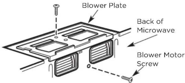
-
Replace the blower plate in the same position as before with the screw. Make sure the screw is tight.
-
Attach the exhaust adaptor to the rear of the oven by sliding it into the guides at the top center of the back of the oven.
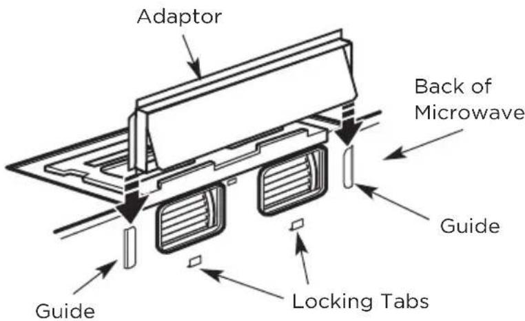
Push in securely until it is in the lower locking tabs. Take care to assure that the damper hinge is installed so that it is at the top and that the damper swings freely.
B6. MOUNT THE MICROWAVE OVEN
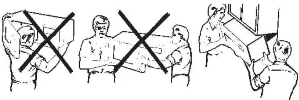
natural_image
Three-panel line drawing showing a person handling boxes and another with crossed-out boxes, no text or symbols present.FOR EASIER INSTALLATION AND PERSONAL SAFETY, WE RECOMMEND THAT TWO PEOPLE INSTALL THIS MICROWAVE OVEN.
IMPORTANT: Do not grip or use the handle or heat shield during in-stallation. Do not remove the cardboard spacers between the heat shield and door.

NOTE:
If your cabinet is metal, use the nylon grommet around the power cord hole to prevent cutting of the cord.

NOTE:
We recommend using filler blocks of the cabinet front hangs below the cabinet bottom shelf.
IMPORTANT: If filler blocks are not used, case damage may occur from over tightening screws.
NOTE: When mounting the microwave oven, thread power cord through hole in bottom of top cabinet. Keep it tight throughout steps 1-3. Do not pinch cord or lift oven by pulling cord.
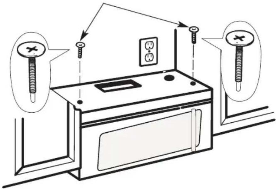
- Insert self-aligning screw through top center cabi-net hole. Temporarily secure the oven by turning the screw at least two full turns after the threads have engaged (it will be completely tightened later). Be sure to keep the power cord tight. Be careful not to pinch the cord, especially when mounting flush to bottom of cabinet.
-
Attach the microwave oven to the top cabinet.
-
Insert 2 self-aligning screws through outer top cabinet holes. Turn two full turns on each screw.
- Tighten the outer two screws to the top of the microwave oven. (While tightening screws, hold the microwave oven in place against the wall and the top cabinet.)

natural_image
Hand inserting a small rectangular object into a grid-patterned panel (no text or symbols visible)- Install grease filters. See the Use & Care Guide that came with the microwave for more information.
C. RECIRCULATING (non vented ductless)
INSTALLATION OVERVIEW
C1. Attach Mounting Plate to Wall
C2. Prepare Top Cabinet
C3. Check Blower Plate
C4. Mount the Microwave Oven
C5. Install or change Charcoal Filter
IMPORTANT NOTES:
- Make sure the screws for the blower motor and blower plate are securely tightened when they are reinstalled. This will help prevent excessive vibration.
- Make sure the motor wiring has been properly routed and secured and that the wires are not pinched.
C1. ATTACH THE MOUNTING PLATE TO THE WALL
natural_image
Technical line drawing of a structural assembly with no visible text or symbolsAttach the plate to the wall using toggle bolts. At least one wood screw must be used to attach the plate to a wall stud.
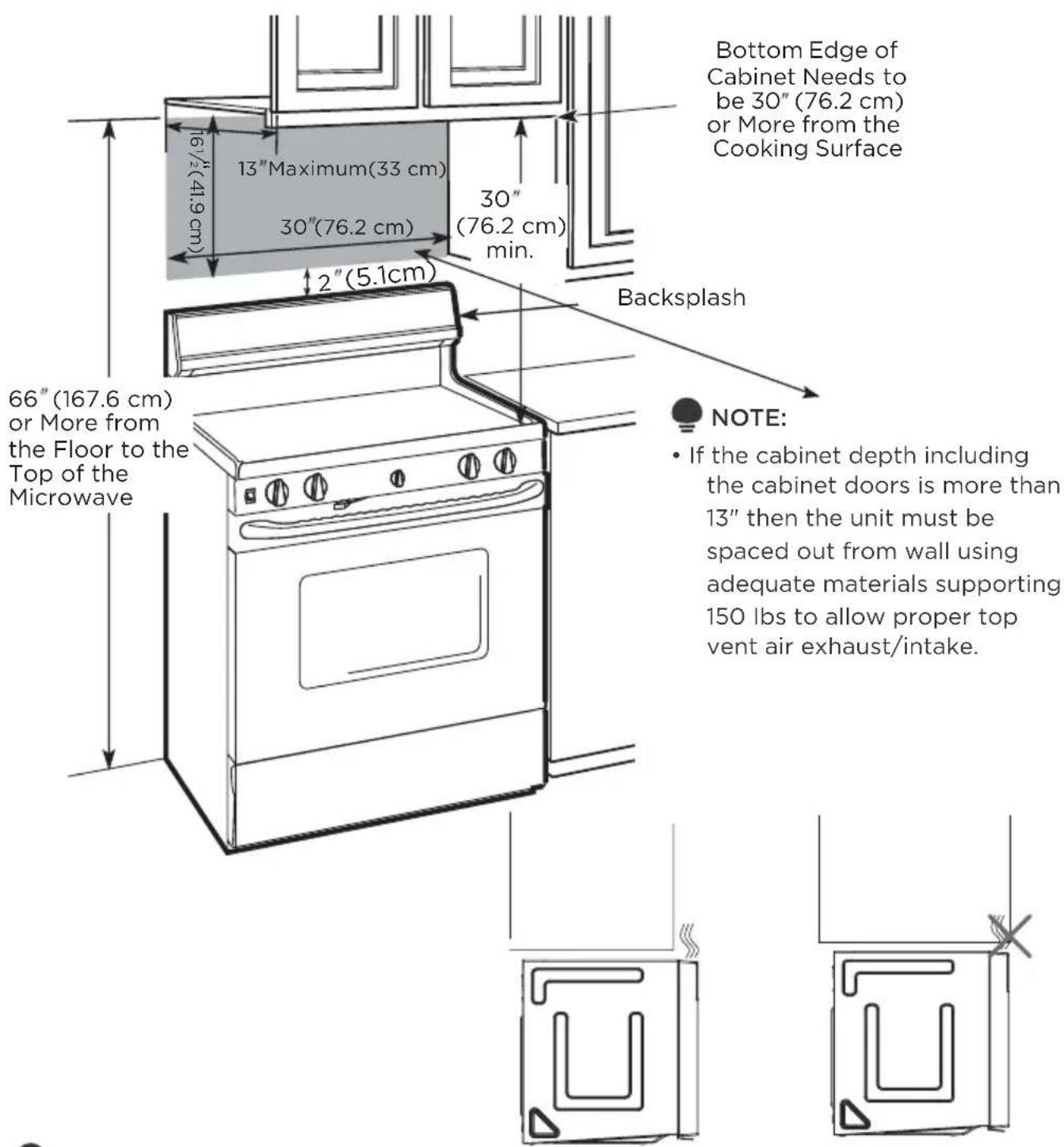
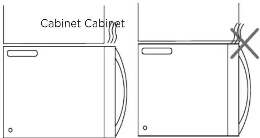
If the cabinet depth including the cabinet doors is more than 13", then the unit must be spaced out from wall using adequate materials supporting 150 lbs to allow proper top vent air exhaust/intake.
- Remove the toggle wings from the bolts.
- Insert the bolts into the mounting plate through the holes designated to go into drywall and reattach the toggle wings 3/4" to (19mm) onto each bolt.
To use toggle bolts:
- Place the mounting plate against the wall and insert the toggle wings into the holes in the wall to mount the plate.

NOTE:
Before tightening toggle bolts and wood
screw, make sure the bottom of the mounting plate touch the bottom of the cabinet when pushed flush against the wall and that the plate is properly centered under the cabinet.

CAUTION:
Be careful to avoid pinching fingers between the back of the mounting plate and the wall.
- Tighten all bolts. Pull the plate away from the wall to help tighten the bolts.
C2. USE TOP CABINET TEMPLATE FOR PREPARATION OF TOP CABINET
You need to drill holes for the top support screws and a hole large enough for the power cord to fit through.
natural_image
Line drawing of a hand using a tool to clean or store items on a kitchen counter (no text or symbols)- Read the instructions on the TOP CABINET TEMPLATE.
- Tape it underneath the top cabinet.

NOTE:
Adjust top template accordingly if the microwave is being spaced out from the wall due to cabinet depth (including cabinet doors) of more than 13".
Drill the holes following instructions on the TOP CABINET TEMPLATE.

CAUTION:
Wear safety goggles when drilling holes in the cabinet bottom.
C3. CHECK BLOWER PLATE
Place the microwave in its upright position, with the top of the unit facing up. Check to see that the blower plate is correctly installed on the unit.
natural_image
Three-panel line drawing showing a person crossed out of a box, another with a cross symbol, and a third holding an object (no text or symbols present)FOR EASIER INSTALLATION AND PERSONAL SAFETY, WE RECOMMEND THAT TWO PEOPLE INSTALL THIS MICROWAVE OVEN.
IMPORTANT: Do not grip or use the handle or heat shield during installation. Do not remove the cardboard spacers between the heat shield and door.

NOTE:
If your cabinet is metal, use the nylon grommet around the power cord hole to prevent cutting of the cord.

NOTE:
We recommend using filler blocks if the cabi-net front hangs below the cabinet bottom shelf.
IMPORTANT: If filler blocks are not used, case dam-age may occur from over tightening screws.
NOTE: When mounting the microwave oven, thread power cord through hole in bottom of top cabinet. Keep it tight throughout steps 1-3. Do not pinch cord or lift oven by pulling cord.
-
Rotate front of oven up against cabinet bottom.
-
Lift microwave, tilt it forward, and hook slots at back bottom edge onto four lower tabs of mounting plate.
natural_image
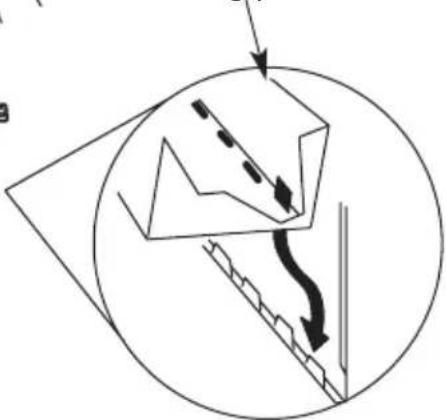
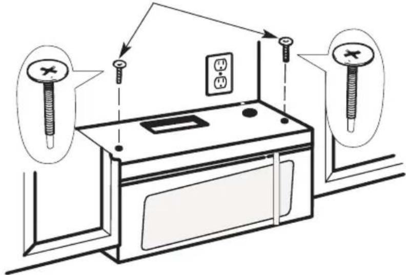
Diagram showing a mechanical or structural component inside a circular frame, with arrows indicating direction (no text or symbols present)- Insert a self-aligning screw through top center cabinet hole. Temporarily secure the oven by turning the screw at least two full turns after the threads have engaged (It will be completely tightened later.) Be sure to keep power cord tight. Be careful not to pinch the cord, especially when mounting flush to bottom of cabinet.
-
Attach the microwave oven to the top cabinet.
-
Insert 2 self-aligning screws through outer top cabinet holes. Turn two full turns on each screw.
- Tighten the outer two screws to the top of the microwave oven. (While tightening screws, hold the microwave oven in place against the wall and the top cabinet.)
natural_image
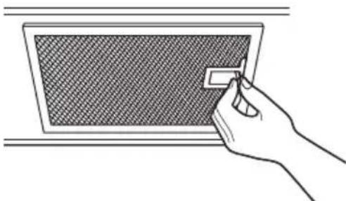
Hand inserting a small rectangular object into a grid-patterned panel (no text or symbols)- Install grease filters. See the Use & Care Guide packed with the microwave.
C5. INSTALLING OR CHANGING THE CHARCOAL FILTER (Some Models)

NOTE:
The charcoal filter is factory installed in some models. Refer to the Use & Care Guide to see if yours is factory installed and for replacement information.
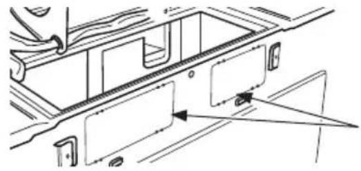
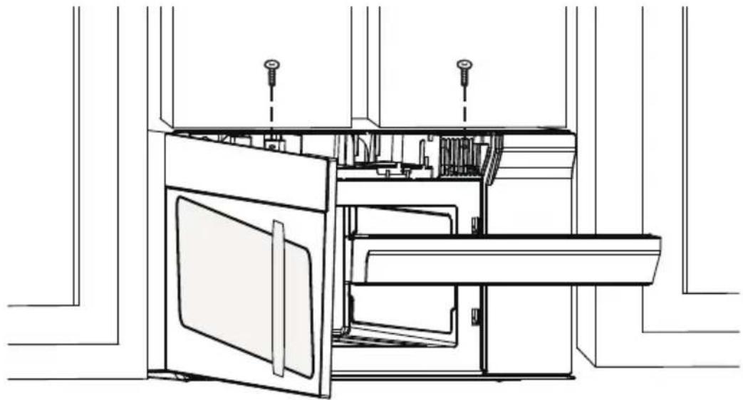
For models without the recirculation filter access door, follow these steps to replace or install a charcoal filter:
-
Unplug microwave oven or disconnect power.
-
Open the microwave door and remove the two vent mounting screws located on top of the microwave using a #1 Phillips screwdriver.
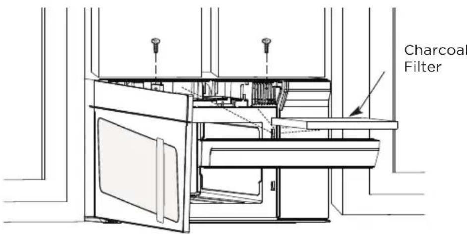
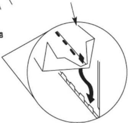
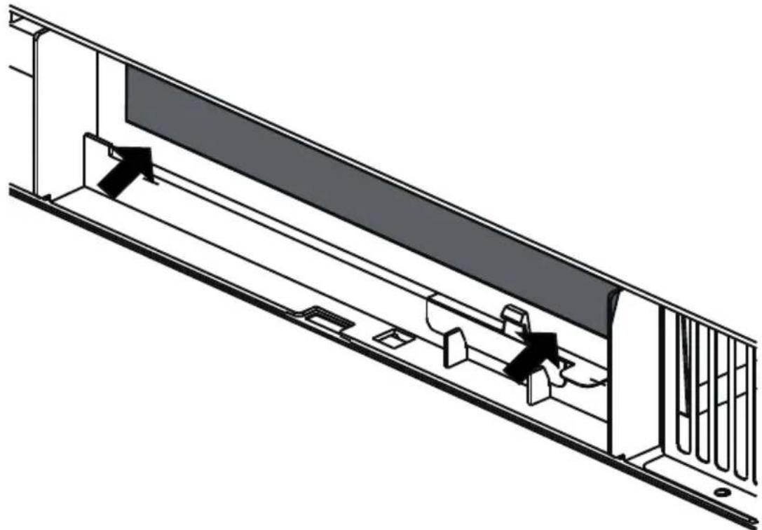
- Remove the charcoal filter by pushing the top of the filter inwards, then pull it forward out from the unit.
natural_image
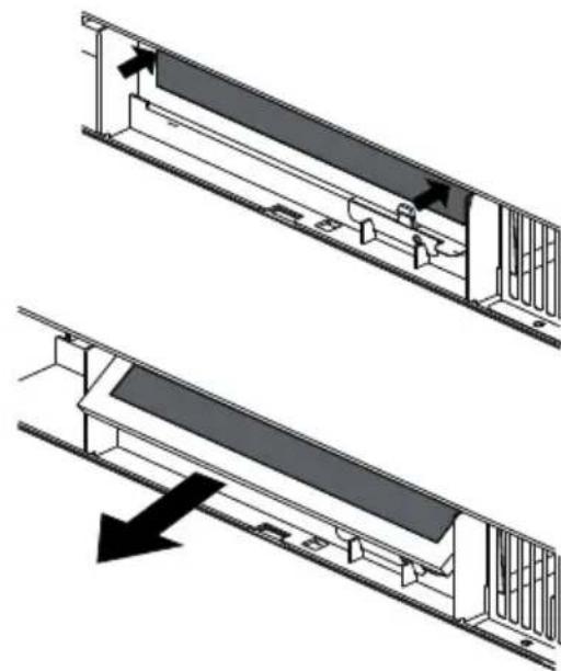
Technical diagram showing two views of a mechanical assembly with arrows indicating direction (no text or symbols present)- Slide the top of the new charcoal filter into the top of the filter cavity.

natural_image
Technical diagram of a mechanical assembly with directional arrows indicating motion or force (no text or symbols present)- Press the bottom of charcoal filter to place it into the correct position.
natural_image
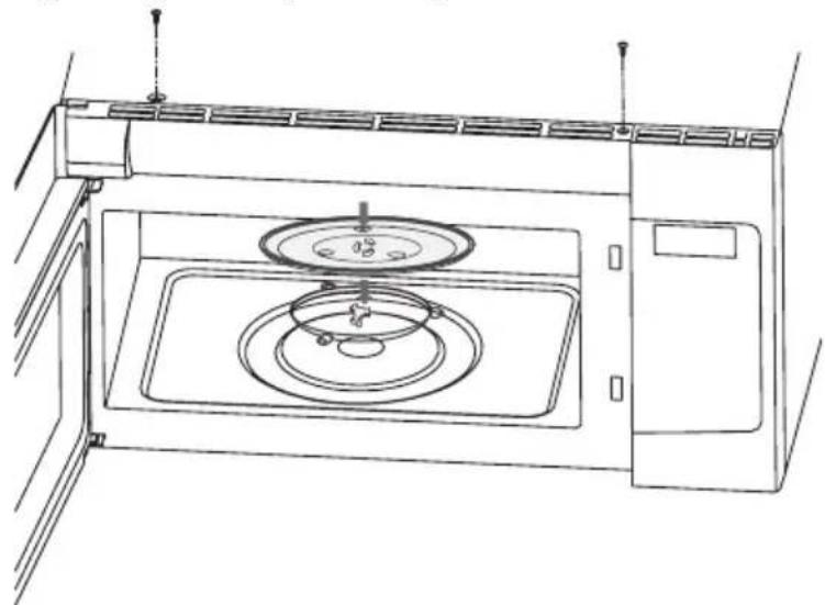
Technical line drawing of a mechanical assembly with internal components and mounting brackets (no text or symbols)- Reinstall the vent by sliding the bottom of the vent into place. Push the vent top into position and slide right into place. Replace the two vent mounting screws located on top of the microwave using a #1 Phillips screwdriver.
natural_image
Technical line drawing of an open refrigerator with doors and ventilation slots (no text or symbols)- Close the microwave door. Plug in microwave oven or reconnect power.
Before You Use Your Microwave
- Make sure the microwave oven has been installed according to instructions.
-
Remove all packing material from the microwave oven.
-
Install turntable ring and glas stray in cavity.
natural_image
Line drawing of a microwave oven with a circular fan and control panel (no text or symbols)- Plug power cord into a separate and dedicated 15- to 20-amp electrical outlet.
- Replace house fuse or turn breaker back on.
natural_image
Illustration of a hand inserting a 3-pin electrical outlet into an electrical box (no text or symbols)- Read the User Manual.
- KEEP USER MANUAL FOR THE LOCAL INSPECTOR'S USE.
Operational Check
- Make sure the unit has been installed according to these instructions.
- Remove all packing materials from the oven.
- Replace house fuse or turn circuit breaker back on.
- Plug power cord into receptacle.
- Read operating instructions before testing the product.
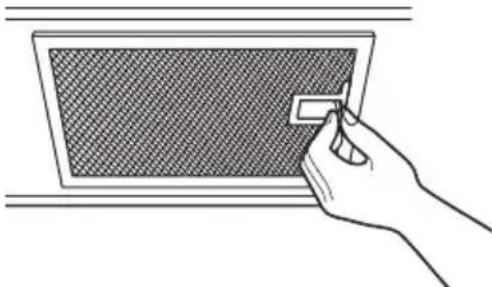
- Turn on the exhaust fan at Turbo speed and confirm it is operating by using a tissue (it will stick to the filter).
- Confirm the outdoor ex-haust flapper has opened.
- Set the microwave oven for 1 minute and confirm the oven is operat-ing normally using a cup of water.
- Keep these installation instruction for the local electrical inspector's use.
OPERATION INSTRUCTIONS
Control Panel
natural_image
Empty rectangular frame with no text, symbols, or markingsAUTO MENU AND PRESETS
| VEGGIES | POPCORN | POTATO |
| SNACK MENU | MELT /SOFTEN | AUTO MENU |
| 1 | 2 | 3 |
| EXPRESS COOK | ||
| 4 | 5 | 6 |
| 7 | 8 | 9 |
- Suppose you want to enter the correct time of day 10:59.
| TOUCH DISPLAY SHOWS | : | |
| 1. CLOCK | 12:00 | |
| 2. | 1 0 5 9 | PRESS START10:59 |
| 3. | CLOCK or START +30SEC. | 10:59 |
Setting The Timer
Your microwave oven can be used as a kitchen timer. You can set up to 99 minutes, 99 seconds. The kitchen timer can be used while the microwave oven is running.
- Suppose you want to set for three minutes.
| TOUCH DISPLAY SHOWS | : | |
| 1. TIMER | TIMER : 0 | |
| 2. | 3 0 0 | TIMER 3:00 |
| 3. TIMER | TIMER 3:00Time counting down | |

NOTE:
There are not any other programs during the kitchen timer.
Microwave
Your Over the Range Microwave Oven can be programmed for 99 minutes 99 seconds (99:99). Always enter the seconds after the minutes, even if they are both zeros.
- Suppose you want to cook for 2 minutes at 90 % power
| TOUCH DISPLAY SHOWS | : | |
| 1. COOK TIME | : 0 | |
| 2. | 2 0 0 | PRESS START2:00 |
| 3. | POWER LEVEL X1 | PRESS STARTP-H1 |
| 4. | 9 | PRESS STARTP-90 |
| 5. Time counting down 20SEC. | ||
Power Chart
| POWER LEVEL DISPLAY | |
| 100% P-HI | |
| 90% P-90 | |
| 80% P-80 | |
| 70% P-70 | |
| 60% P-60 | |
| 50% P-50 | |
| 40% P-40 | |
| 30% P-30 | |
| 20% P-20 | |
| 10% P-10 | |
| 0% P-0 |
Weight Defrost
| TOUCH DISPLAY SHOWS | : | |
| 1. | DEFROST X1 | 0.0b |
| 2. | 1 2 | 1.2PRESS STARTlb |
| 3. Time counting STARTn+30SEC. | ||

NOTE:
The weight amount must be a valid entry for this feature to start. A valid weight entry is 0.1 to 6.0 lbs.
Time Defrost
| TOUCH DISPLAY SHOWS | : | |
| 1. | DEFROST X2 | 0:00 |
| 2. | 1 0 5 8 | PRESS START10:58 |
| 3. | START +30SEC. | COOK DEFR. 10:58Time counting down |

NOTE:
The buzzer will sound to remind you of turning over the food when half of the time has passed on.
SpeedyCooking
1. Using add 30 seconds:
This is a time-saving pad. It is a simplified feature that lets you quickly set and start microwave cooking at 100% power.
| TOUCH DISPLAY SHOWS | : | |
| 1. | START +30SEC. | cook :30 |
2. Using number pads for "1-6":
Press number pads "1-6" to start cooking with corresponding time for 100% power level directly. For example, cooking with 6 minutes for 100% power level.
| TOUCH DISPLAY SHOWS | : | |
| 1. | 6 | PRESS START: 6 |
| 2. After 2 seconds | DOOK 6:00 | |
The oven door should be opened and closed in 5 minutes before the speedy cooking, otherwise, operating as below.
| TOUCH DISPLAY SHOWS | : | |
| 1. | 6 | Food |
| 2. open the door | PRESS START6:00 | |
| 3. Time counting Start+Close the door) | ||

NOTE:
"Food" will be displayed if the number keys 1 to 6 or " START +30SEC. " key is not selected within 5 minutes of placing food in the oven. You must open then close the door again to clear "Food" from the display. And then press ?? START +30SEC. " to start cooking.
Veggies
| TOUCH DISPLAY SHOWS | : | |
| 1. VEGGIES X1 | Fr-1 | |
| 2. | VEGGIES X1 | Fr-2 |
| 3. | 1 | ICUP PRESS START |
| 4. | START +30SEC. | Time counting down |
| PRESS VEGGIES PAD | FOOD AMOUNTNUMDER KEYS | |
| X1 | Fresh Vegetable 1 - 4 cup§ 2, 3, 4 | |
| X2 | Frozen Vegetable 1 - 4 cup§2, 3, 4 |
Popcorn
Press "POPCORN" key and LED displays 3.3 oz. Press "POPCORN" repeatedly to choose the desired weight.
- Suppose you want to cook 3.0 oz. popcorn.
| TOUCH DISPLAY SHOWS | : | |
| 1. | POPCORN X1 | PRESS START3.3 +2 |
| 2. | POPCORN X1 | PRESS START3.0 +2 |
| 3. | Time counting 30ArdWm30SEC. | |
| PRESS POPCORN PADOR NUMDER KEYS | AMOUNT |
| X1 3.3 oz | |
| X2 3.0 oz | |
| X3 1.75 oz |
Potato
| TOUCH DISPLAY SHOWS | : | |
| 1. POTATO X1 | PRESS START1 | |
| 2. POTATO X1 or 2 | PRESS START2 | |
| 3. Time counting down START +30SEC. | ||
| PRESS POTATO PAD OR NUMDER KEYS AMOUNT | |
| X1 | 1 |
| X2 | 2 |
| X3 | 3 |
| X4 | 4 |
Snack Menus
There are 4 options (Hot dogs?? Frozen Kids Meal, Meal In A Cup, Soup) under the snack menu.
- Hot dogs or Soup
| TOUCH DISPLAY SHOWS | : | |
| 1. SNACK MENUS X1 | 5n-1 | |
| 2. | 1 | PRESS START |
| 3. Time counting down+30SEC. | ||
- Frozen Kids Meal
| TOUCH DISPLAY SHOWS | : | |
| 1. | SNACK MENUS X2 | PRESS START5n-2 |
| 2. Time counting START n+30SEC. | ||
| PRESS SNACK MENUS PAD | FOOD AMOUNT | NUMDER KEYS | |
| X1 Hot Dogs 1 - | 6 pieces | 1, 2, 3, 4??,5,6 | |
| X2 Frozen Kids | Meal | 8.8 oz | |
| X3 | Meal in a cup | - | 2.39 oz |
| X4 | Soup | 1, 2, | 1 - 2 cups |
Auto Menu
There are 5 options (Bacon, Dinner Plate, Rice, Frozen breakfast, Frozen Pizza) under the auto cook.
| TOUCH DISPLAY SHOWS | : | |
| 1. | AUTO MENU X1 | R_C-1 |
| 2. | 2 | PRESS START2 |
| 3. Time counting down+30SEC. | ||
| PRESS AUTO MENU FOOD AMOUNT | NUMDER KEYS | |
| X1 Bacon 1-3 Slices | 1, 2, 3, | |
| X2 Dinner Plate 1-2 Plates | 1, 2, | |
| X3 Rice 1-2 Cups | 1, 2, | |
| X4 Frozen breakfast 8/12 oz | 1, 2, | |
| X5 Frozen Pizza 6/8/12 oz | 1, 2, 3, | |
Melt/Soften
The oven uses low power to melt and soften items. See the following table.
- Suppose you want to melt 2 sticks of Butter.
| TOUCH DISPLAY SHOWS | : | |
| 1. | MELT/SOFTEN X 1 | 50-1 |
| 2. | 2 | PRESS START2 |
| 3. | START +30SEC. | Time counting down |
| PRESS MELT/SOFTEN PAD | FOOD | NUMDER KEYS | AMOUNT |
| X1 | Melt Butter | 1, 2, | 1/2 stick |
| X2 | Melt Chocolate | 1, 2, 3, | 2/4/8 oz |
| X3 | Soften Ice Cream | 1, 2, | Pint/1.5Quart |
| X4 | Soften Cream Cheese | 1, 2, | 3/8 oz |
Child Lock
| TOUCH | DISPLAY SHOWS: | |
| 1. | STOP/CLEAR(for 3 seconds) | LOCKOR11:00(if clock is set) |
| 2. | STOP/CLEAR(for 3 seconds) | 11:00(if clock is set) |
Stage Cook
| TOUCH DISPLAY SHOWS | : | |
| 1. | \CO\OK TIME | : 0 |
| 2. | 1 2 0 | PRESS START1:20 |
| 3. | POWER LEVEL X1 | PRESS STARTP-H1 |
| 4. | POWER LEVEL X8 or | PRESS STARTP-20 |
| 5. | \CO\OK TIME | : 0 |
| 6. | 1 5 0 | PRESS START1:50 |
| 7. | POWER LEVEL X1 | PRESS STARTP-H1 |
| 8. | POWER LEVEL X7 or 3 | PRESS STARTP-30 |
| 9. | START +30SEC. | Time counting down |
Vent Fan
The pad controls the 2-speed vent fan. If the vent fan is OFF, the first touch of the FAN pad will turn the fan on HIGH, second touch LOW and third touch OFF.
| TOUCH DISPLAY SHOWS | : | |
 FAN FAN | X1 HI | |
 FAN FAN | X2 Lo | |
 FAN FAN | X3\ |  |
Light
The pad controls the 2-states light. If the light is OFF, the first touch of the light pad will turn the light on, second touch OFF.
Clock Display Off/On
In standby mode:
| TOUCH DISPLAY SHOWS | : | |
| 1. USER PREF X3 | PRESS START | |
| 2. | START +30SEC. | PRESS START bowlPRESS START bowlPRESS START |
| 3. | START +30SEC. | |
Demo Mode
In standby mode:
| TOUCH DISPLAY SHOWS | : | |
| 1. USER PREF X4 | PRESS START | |
| 2. | START +30SEC. | PRESS START [YBT7]PRESS START [YBT7]PRESS START |
| 3. | START +30SEC. | |
TROUBLESHOOTING
Check your problem by using the chart below and try the solutions for each problem. If the microwave oven still does not work properly, contact the nearest authorized service center.
| TROUBLE POSSIBLE CAUSE POSSIBLE REMEDY | ||
| Oven will not start | Electrical cord for oven is not plugged in.Door is open.Wrong operation is set. | Plug into the outlet.Close the door and try again.Check instructions. |
| Arcing or sparking | Materials to be avoided in microwave oven were used.The oven is operated when empty.Spilled food remains in the cavity. | Use microwave-safe cookware only.Do not operate with oven empty.Clean cavity with wet towel. |
| Unevenly cooked foods | Materials to be avoided in microwave oven were used.Food is not defrosted completely.Cooking time, power level is not suitable.Food is not turned or stirred. | Use microwave-safe cookware only.Completely defrost food.Use correct cooking time, power level.Turn or stir food. |
| Overcooked foods | Cooking time, power level is not suitable. | Use correct cooking time, power level. |
| Undercooked foods | Materials to be avoided in microwave oven were used.Food is not defrosted completely.Oven ventilation ports are restricted.Cooking time, power level is not suitable. | Use microwave-safe cookware only.Completely defrost food.Check to see that oven venti- lation ports are not restricted.Use correct cooking time, power level. |
| Improper defrosting | Materials to be avoided in microwave oven were used.Cooking time, power level is not suitable.Food is not turned or stirred. | Use microwave-safe cookware only.Use correct cooking time, power level.Turn or stir food. |
TRADEMARKS, COPYRIGHTS AND LEGAL STATEMENT
Midea logo, word marks, trade name, trade dress and all versions thereof are valuable assets of Midea Group and/or its affiliates ("Midea"). to which Midea owns trademarks, copyrights and other intellectual property rights, and all goodwill derived from using any part of an Midea trademark. Use of Midea trademark for commercial purposes without the prior written consent of Midea may constitute trademark infringement or unfair competition in violation of relevant laws.
This manual is created by Midea and Midea reserves all copyrights thereof. No entity or individual may use, duplicate, modify, distribute in whole or in part this manual, or bundle or sell with other products without the prior written consent of Midea.
All the described functions and instructions were up to date at the time of printing this manual. However, the actual product may vary due to improved functions and designs.
DATA PROTECTION NOTICE
For the provision of the services agreed with the customer,
we agree to comply without restriction with all stipulations of applicable data protection law, in line with agreed countries within which services to the customer will be delivered.
Generally, our data processing is to fulfil our obligation under contract with you and for product safety reasons, to safeguard your rights in connection with warranty and product registration questions. In some cases, but only if appropriate data protection is ensured, personal data might be transferred to recipients located outside of the European Economic Area.
Further information are provided on request. You can contact our Data Protection Officer via MideaDPO@midea.com. To exercise your rights such as right to object your personal date being processed for direct marketing purposes, please contact us via MideaDPO@midea.com. To find further information, please follow the QR Code.
1 YEAR LIMITED WARRANTY
This warranty is provided to the delivery at retail (the “Purchaser” or “you”) by Midea America Corp. (“Midea” or “we”), which warrants all parts of this Product, as described below. Midea warrants this Product to the Purchaser for personal, family or household use. This warranty covers performance and quality issues in materials and workmanship that appear under normal use and maintenance appearing within one year from the date of purchase. This warranty gives you specific rights, and you may also have other rights that vary from state to state. The date of delivery establishes the warranty period, should service be required.
WARRANTY LIMITATIONS
This warranty is given only to the delivery at retail in either the United States or Canada and may not be transferred to any subsequent buyer. This warranty does not apply to purchasers of our products for use or resale in a business; a separate commercial warranty may protect those purchasers.
This warranty does not cover any Product failure caused by:
a. Abuse, damage or use of the Product in violation of the Product instructions.
b. Modification to any Product or part.
c. Failure to maintain the Product or part as described in accordance with the Product instructions.
d. Faulty installation or application.
e. Use of parts or accessories not compatible with this Product.
f. Floods, fires, winds, lightning, accidents, corrosive atmosphere , or other conditions beyond Midea's control.
g. Interruption in electrical service or inadequate electrical service.
h. Replacement of fuses and replacement or resetting of circuit breakers.
i. Frozen or broken water pipes, water damage, moisture intrusion, mold or other biological growth.
j. The use, combination or linking of the Product to other products, processes or materials not provided by Midea.
WARRANTY REMEDY
If any quality or performance issue covered by this warranty is discovered during the warranty period, we will, at our option, repair or replace any such Product. This warranty is limited to Product repair or replacement by an authorized Midea servicer or dealer and does not cover any shipping cost, labor cost, customs duties, inland logistics cost, or cost of service, including any diagnostics, removal, transportation, or reinstallation costs. If we ask, you must return the Product to us.
WARRANTY DISCLAIMER; EXCLUSION OF DAMAGES
This is the only express warranty to consumers that we offer on our Products. ANY IMPLIED WARRANTIES BY MIDEA, INCLUDING BUT NOT LIMITED TO WARRANTIES OF MERCHANTABILITY AND FITNESS FOR PARTICULAR PURPOSE, ARE LIMITED TO THE DURATION OF THIS EXPRESS WARRANTY. Some states and provinces do not allow the exclusion of express warranties and/or limitations on how long an implied warranty lasts, so the above exclusion and/or limitation may not apply to you.
THE REMEDY DESCRIBED ABOVE IS THE ONLY ONE THAT WE WILL PROVIDE, EITHER UNDER THIS WARRANTY OR UNDER ANY WARRANTY ARISING BY OPERATION OF LAW. WE WILL NOT BE RESPONSIBLE FOR ANY CONSEQUENTIAL OR INCIDENTAL DAMAGES ARISING FROM THE BREACH OF THIS WARRANTY OR ANY OTHER WARRANTY, WHETHER EXPRESS OR IMPLIED, NEGLIGENCE OR OTHER TORT, OR ON
ANY STRICT LIABILITY THEORY, INCLUDING BUT NOT LIMITED TO LOST PROFITS.
Some states do not allow the exclusion or limitation of incidental or consequential damages, so the above exclusion may not apply to you.
WARRANTY CLAIMS PROCESS
For more information or to make a warranty claim, please visit:
https://www.midea.com/Canada/support
Or contact us at:
Telephone: 1-888-365-2230
Email: CanadaSupport@midea.com
You must have Your bill of sale, delivery slip, or appropriate proof of purchase to submit a warranty claim. The date of purchase establishes the warranty period, should service be required.
DISPUTE RESOLUTION
ARBITRATION CLAUSE. IMPORTANT. PLEASE REVIEW THIS ARBITRATION CLAUSE. IT AFFECTS YOUR LEGAL RIGHTS.
a. Parties: This arbitration clause (this “Arbitration Clause”) affects your rights against Midea and any of its affiliates or employees or agents, successors, or assigns, all of whom together are referred to below as “we” or “us” for ease of reference.
b. ARBITRATION REQUIREMENT: EXCEPT AS STATED BELOW, ANY DISPUTE BETWEEN YOU AND ANY OF US SHALL BE DECIDED BY NEUTRAL, BINDING ARBITRATION RATHER THAN IN COURT OR BY JURY TRIAL. “Dispute” will be given the broadest possible meaning allowable by law. It includes any dispute, claim, or controversy arising from or relating to your purchase of this Product, any warranty upon the Product, or the Product’s condition. It also includes determination of the scope or applicability of this Arbitration Clause. The arbitration requirement applies to claims in contract and tort, pursuant to statute, or otherwise.
C. CLASS-ARBITRATION WAIVER: ARBITRATION IS HANDLED ON AN INDIVIDUAL BASIS. IF A DISPUTE IS ARBITRATED, YOU AND WE EXPRESSLY WAIVE ANY RIGHT TO PARTICIPATE AS A CLASS REPRESENTATIVE OR CLASS MEMBER ON ANY CLASS CLAIM YOU MAY HAVE AGAINST US OR WE AGAINST YOU, OR AS A PRIVATE ATTORNEY GENERAL OR IN ANY OTHER REPRESENTATIVE CAPACITY, TO THE MAXIMUM EXTENT PERMITTED BY LAW. YOU AND WE ALSO WAIVE ANY RIGHT TO CLASS ARBITRATION OR ANY CONSOLIDATION OF INDIVIDUAL ARBITRATIONS.
d. Discovery and Other Rights: Discovery and rights to appeal in arbitration are generally more limited than in a lawsuit. This applies to both you and us. Other rights that you or we would have in court may not be available in arbitration. Please read this Arbitration Clause and consult the rules of the arbitration organizations listed below for more information.
e. SMALL CLAIMS COURT OPTION: YOU MAY CHOOSE TO LITIGATE ANY DISPUTE BETWEEN YOU AND ANY OF US IN SMALL CLAIMS COURT, RATHER THAN IN ARBITRATION, IF THE DISPUTE MEETS ALL REQUIREMENTS TO BE HEARD IN SMALL CLAIMS COURT.
f. Governing Law: For residents of the United States, the procedures and effect of the arbitration will be governed by the Federal Arbitration Act (9 U.S.C. § 1 et seq.) rather than by state law concerning arbitration. For residents of Canada, the procedures and effect of the arbitration will be governed by the applicable arbitration law of the province in which you purchased your Product. The law governing your substantive warranty rights and other claims will be the law of the state or province in which you purchased your Product. Any court having jurisdiction may enter judgment on the arbitration award.
g. Rules of the Arbitration: If the amount in controversy is less than \$250,000, the
arbitration will be decided by a single arbitrator. If the amount in controversy is greater than or equal to \$250,000, the arbitration will be decided by a panel of three arbitrators. The arbitrator(s) will be chosen pursuant to the rules of the administering arbitration organization. United States residents may choose JAMS (1920 Main Street, Ste. 300, Irvine, CA 92614, www.jamsadr.com), or, subject to our approval, any other arbitration organization. In addition, Canadian residents may choose the ADR Institute of Canada (234 Eglinton Ave. East, Suite 405, Toronto, Ontario, M4P 1K5, www.amic.org). These organizations' rules can be obtained by contacting the organization or visiting its website. If the chosen arbitration organization's rules conflict with this Arbitration Clause, the provisions of this Arbitration Clause control. The award of the arbitrator(s) shall be final and binding on all parties.
h. Location of the Arbitration Hearing: Unless applicable law provides otherwise, the arbitration hearing for United States residents will be conducted in the federal judicial district in which you reside (in your hometown area) or, for Canadian residents, in the province in which you reside, and, if you choose, will be in-person.
i. Costs of the Arbitration: Each party is responsible for its own attorney, expert, and other costs and fees unless applicable law requires otherwise. Notwithstanding the preceding sentence, and unless applicable law requires otherwise, if you are a consumer under the JAMS rules or the rules of another agreed upon arbitration administrator, Midea will pay or reimburse you for all reasonable fees or costs to the extent required by law or the applicable arbitration administrator's rules. Whether or not required by law or such rules, if you prevail at arbitration on any claim against Midea, Midea will reimburse you for any reasonable fees paid to the arbitration administrator in connection with the arbitration proceedings. Under no circumstances will Midea seek from you payment or reimbursement of any reasonable fees that Midea incurs in connection with the arbitration. If you are required to advance any fees or costs to JAMS or other agreed upon arbitration administrator, but you ask Midea to do so in your stead, Midea will consider and respond to your request.
j. Survival and Enforceability of this Arbitration Clause: This Arbitration Clause shall survive the expiration or termination, or any transfer, of the warranty on your Product. If any part of this Arbitration Clause, except waivers of class-action rights, is found to be unenforceable for any reason, the remainder of this clause and the warranty shall remain enforceable. If, in a case in which class-action allegations have been made, the waiver of class-action rights under this warranty is found to be unenforceable with respect to any part of the dispute, the parts of the dispute as to which the waiver of class-action rights have been found unenforceable will be severed and will proceed in court without reference or application of this Arbitration Clause. Any remaining parts will proceed in arbitration.
QUEBEC RESIDENTS
The arbitration provisions of this warranty shall not apply to residents of Quebec.

make yourself at home
natural_image
Simple line drawing of a microwave oven with a handle and lid (no text or symbols)Prolongation gratuite de
APERÇU DU PRODUIT ----FR-13
INSTALLATION DU PRODUIT ----FR-14
CONSIGNES D'UTILISATION----FR-53
DÉPANNAGE ----FR-64
MARQUES, DROITS D'AUTEUR ET DÉCLARATION LÉGALE ----FR-65
AVIS DE PROTECTION DES DONNÉES ----FR-66
GARANTIE LIMITÉE D'UN AN ----FR-67
CONSIGNES DE SÉCURITÉ
Utilisation prévue
INSTALLATION DU PRODUIT
natural_image
Illustration of a hand inserting a component into an electrical box (no text or symbols visible)
MISE EN GARDE :
Dommages—Expédition/Installation
natural_image
Technical illustration of a drill bit with screw and nut components (no text or symbols)natural_image
Technical line drawing of three mechanical components: a motor, a gear, and a hook (no text or symbols)natural_image
Line drawing of a microwave oven with a black arrow indicating upward motion (no text or symbols)Voir page 41
natural_image
Simple line drawing of a conical object with two flanges (no text or symbols)natural_image
Pure line drawing of a curved pipe or duct with a triangular tip, no text or symbols present
REMARQUE :
REMARQUES IMPORTANTES :
natural_image
Technical line drawing of a structural assembly with beams and supports, no visible text or symbolsnatural_image
Line drawing of a hand using a tool to clean or store items on a kitchen counter (no text or symbols)natural_image
Three-panel line drawing showing a person crossed out of a box, another with a cross symbol, and a third holding a box (no text or symbols present)POUR FACILITER L'INSTALLATION ET PROCURER LA SÉCURITÉ PERSONNELLE, NOUS VOUS RECOMMANDONS QUE DEUX PERSONNES INSTALLENT CE FOUR À MICRO-ONDES.
natural_image
Hand inserting a small rectangular object into a grid-patterned panel (no text or symbols visible)REMARQUES IMPORTANTES :
natural_image
Architectural cross-section diagram showing structural components and lighting fixtures (no text or labels)natural_image
Line drawing of a hand cleaning a kitchen appliance with a tool, no text or symbols presentnatural_image
Technical line drawing of a vehicle chassis frame with mounting brackets and structural components (no text or symbols)natural_image
Three-panel line drawing showing a person holding a box, another with a cross symbol, and a third with a person assembling a cabinet (no text or symbols present)POUR FACILITER L'INSTALLATION ET PROCURER LA SÉCURITÉ PERSONNELLE, NOUS VOUS RECOMMANDONS QUE DEUX PERSONNES INSTALLENT CE FOUR À MICRO-ONDES.
natural_image
Hand inserting a small rectangular object into a grid-patterned panel (no text or symbols visible)REMARQUES IMPORTANTES :
natural_image
Architectural cross-section diagram showing structural components and lighting fixtures (no text or labels)natural_image
Line drawing of a hand cleaning a window with a tool, no text or symbols presentnatural_image
Technical line drawing of a mechanical component with mounting holes and a bracket (no text or symbols)natural_image
Three-panel line drawing showing a person crossed out of a box, another with a cross on a table, and a third holding an object (no text or symbols)POUR FACILITER L'INSTALLATION ET PROCURER LA SÉCURITÉ PERSONNELLE, NOUS VOUS RECOMMANDONS QUE DEUX PERSONNES INSTALLENT CE FOUR À MICRO-ONDES.
natural_image
Hand inserting a small rectangular object into a grid-patterned panel (no text or symbols visible)natural_image
Technical diagram showing two views of a mechanical assembly with no visible text or symbolsnatural_image
Technical diagram of a mechanical or electrical component with directional arrows indicating movement or flow (no text or symbols present)natural_image
Technical line drawing of a mechanical assembly with internal components and mounting brackets (no text or symbols)natural_image
Technical line drawing of an open refrigerator with doors and ventilation slots (no text or symbols)natural_image
Line drawing of a microwave oven with a circular vent and fan (no text or symbols)natural_image
Line drawing of a hand inserting a box into an electrical outlet (no text or symbols)- CONSERVEZ LE MANUEL D'UTILISATION POUR L'UTILISATION DE L'INSPECTEUR LOCAL.
| NIVEAU DE PUISSANCE Affichage | |
| 100% P-HI | |
| 90% P-90 | |
| 80% P-80 | |
| 70% P-70 | |
| 60% P-60 | |
| 50% P-50 | |
| 40% P-40 | |
| 30% P-30 | |
| 20% P-20 | |
| 10% P-10 | |
| 0% P-0 |
| 1. DÉMARRER + 30 SEC. | cook :30 |
GARANTIE LIMITÉE D'UN AN
RECOURS SOUS GARANTIE
make yourself at home

- USER MANUAL
- THANK YOU LETTER
- CONTENTS
- SAFETY INSTRUCTIONS
- Intended Use
- PRECAUTIONS TO AVOID POSSIBLE EXPOSURE TO EXCESSIVE MICROWAVE ENERGY
- IMPORTANT SAFETY INSTRUCTIONS
- WARNING
- SAVE THESE INSTRUCTIONS
- GROUNDING INSTRUCTIONS
- DANGER
- Electric Shock Hazard
- RADIO INTERFERENCE
- THIS DEVICE COMPLIES WITH PART 18 OF THE FCC RULES.
- UTENSILS
- CAUTION
- Utensil Test:
- Materials you can use in microwave oven
- Materials to be avoided in microwave oven
- PRODUCT OVERVIEW
- Setting Up Your Oven
- PRODUCT INSTALLATION
- CAUTION:
- NOTE:
- Electrical Requirements
- Damage—Shipment/Installation
- Parts Included
- HARDWARE PACKET
- ADDITIONAL PARTS
- Tools You Will Need
- Phillips screwdriver
- MOUNTING SPACE
- Placement Of The Mounting Plate
- REMOVING THE MICROWAVE OVEN FROM THE CARTON/REMOVING THE MOUNTING PLATE
- FINDING THE WALL STUDS
- DETERMINING WALL PLATE LOCATION UNDER YOUR CABINET
- Plate position-beneath flat bottom cabinet
- Plate position-beneath recessed bottom cabinet with front overhang
- Plate position-beneath framed recessed cabinet bottom
- ALIGNING THE WALL PLATE
- Installation Types (Choose A, B or C)
- OUTSIDE TOP EXHAUST (VERTICAL DUCT)
- OUTSIDE BACK EXHAUST (HORIZONTAL DUCT)
- RECIRCULATING (NON-VENTED DUCTLESS)
- Installation Instructions For External Exhaust Ducting
- Exhaust connection:
- Maximum duct length:
- External Exhaust Ducting
- OUTSIDE TOP EXHAUST (EXAMPLE ONLY)
- OUTSIDE BACK EXHAUST (EXAMPLE ONLY)
- INSTALLATION OVERVIEW
- IMPORTANT NOTES:
- A1. ATTACH THE MOUNTING PLATE TO THE WALL
- To use toggle bolts:
- A2. USE TOP CABINET TEMPLATE FOR PREPARATION OF TOP CABINET
- A3. ADAPTING MICROWA VE BLOWER FOR OUTSIDE TOP EXHAUST
- A6. ADJUST THE EXHAUST ADAPTOR
- A7. CONNECTING DUCTWORK
- B1. PREPARING THE REAR WALL FOR OUTSIDE BACK EXHAUST
- B2. REMOVE BLOWER PLATE
- B3. ATTACH THE MOUNTING PLATE TO THE WALL
- B4. USE TOP CABINET TEMPLATE FOR PREPARATION OF TOP CABINET
- B5. ADAPTING MICROWAVE BLOWER FOR OUTSIDE BACK EXHAUST
- B6. MOUNT THE MICROWAVE OVEN
- RECIRCULATING (non vented ductless)
- C1. ATTACH THE MOUNTING PLATE TO THE WALL
- C2. USE TOP CABINET TEMPLATE FOR PREPARATION OF TOP CABINET
- C3. CHECK BLOWER PLATE
- C5. INSTALLING OR CHANGING THE CHARCOAL FILTER (Some Models)
- Before You Use Your Microwave
- Operational Check
- OPERATION INSTRUCTIONS
- Setting The Timer
- Microwave
- Time Defrost
- SpeedyCooking
- Using add 30 seconds:
- Using number pads for "1-6":
- Veggies
- Popcorn
- Potato
- Snack Menus
- Auto Menu
- Melt/Soften
- Stage Cook
- Vent Fan
- Light
- Clock Display Off/On
- Demo Mode
- TROUBLESHOOTING
- TRADEMARKS, COPYRIGHTS AND LEGAL STATEMENT
- DATA PROTECTION NOTICE
- YEAR LIMITED WARRANTY
- WARRANTY LIMITATIONS
- WARRANTY REMEDY
- WARRANTY DISCLAIMER; EXCLUSION OF DAMAGES
- ANY STRICT LIABILITY THEORY, INCLUDING BUT NOT LIMITED TO LOST PROFITS.
- WARRANTY CLAIMS PROCESS
- DISPUTE RESOLUTION
- ARBITRATION CLAUSE. IMPORTANT. PLEASE REVIEW THIS ARBITRATION CLAUSE. IT AFFECTS YOUR LEGAL RIGHTS.
- QUEBEC RESIDENTS
- CONSIGNES DE SÉCURITÉ
- Utilisation prévue
- INSTALLATION DU PRODUIT
- MISE EN GARDE :
- Dommages—Expédition/Installation
- REMARQUE :
- REMARQUES IMPORTANTES :
- GARANTIE LIMITÉE D'UN AN
- RECOURS SOUS GARANTIE
Brand : MIDEA
Model : MMO17S12ASTC
Category : Microwave Oven