
WChip3 - Garden shredder WESTINGHOUSE - Free user manual and instructions
Find the device manual for free WChip3 WESTINGHOUSE in PDF.


| Product Type | Wood Chipper/Shredder |
| Brand | Westinghouse |
| Model | WChip3 |
| No-load Speed | 3600 RPM |
| Maximum Cutting Diameter | 76 mm (3 in) |
| Weight | 62.1 kg (137 lb) |
| Fuel Tank Capacity | 3.6 L (0.95 gal) |
| Fuel Type | Unleaded gasoline (octane rating 87-93) |
| Collection Bag Capacity | 100 L (26.4 gal) |
| Engine Oil Capacity | 0.6 L (20.3 oz) |
| Engine Oil Type | SAE 10W-30 |
| Start Type | Recoil (pull start) |
| Number of Wheels | 2 |
| Main Functions | Shredding and chipping branches up to 76 mm diameter |
| Regular Maintenance | Oil change every 50 h, air filter cleaning, spark plug inspection |
| Safety | Engine stop, wheel locks, CO detection (outdoor use only) |
| Spare Parts | Available from Westinghouse customer service |
| General Information | Warranty after online or mail registration |
Frequently Asked Questions - WChip3 WESTINGHOUSE
User questions about WChip3 WESTINGHOUSE
0 question about this device. Answer the ones you know or ask your own.
Ask a new question about this device
Download the instructions for your Garden shredder in PDF format for free! Find your manual WChip3 - WESTINGHOUSE and take your electronic device back in hand. On this page are published all the documents necessary for the use of your device. WChip3 by WESTINGHOUSE.
USER MANUAL WChip3 WESTINGHOUSE
Service Hot Line/Company Address.. Back Page
INTRODUCTION

WARNING
Operating, servicing, and maintaining this equipment may expose you to chemicals which are known to
the State of California to cause cancer and birth defects or other reproductive harm. To minimize exposure, wear gloves or wash your hands frequently when servicing this equipment. For more information go to www.P65 warnings.ca.gov.
DISCLAIMERS
All information, illustrations, and specifications in this manual were in effect at the time of publishing. The illustrations used in this manual are intended as representative reference views only. We reserve the right to make any specification or design change without notice.
ALL RIGHTS RESERVED
All rights reserved. No reproduction allowed in any form without written permission from Westinghouse Outdoor Power Equipment.


DANGER
Read this manual before using or performing maintenance on this product. Failure to follow the
instructions and safety precautions in this manual can result in serious injury or death.
UPDATES
The latest User Manual for Westinghouse products can be found under the support tab: westinghouse.com/pages/ manuals
Or scan the following QR code with a smartphone camera to be directed to the link.

PRODUCT REGISTRATION
For trouble-free warranty coverage, it is important to register the Westinghouse product.
Register by:
- Completing and mailing the product registration card included in the carton.
- Going online at: westinghouse.com/register
- Scanning the following QR code with a smartphone camera to be directed to the mobile registration link.
For Your Records
Date of Purchase:
Model Number:
Serial Number:
Place of Purchase:

- Sending the following product information to:
Westinghouse Outdoor Power
Warranty registration
777 Manor Park Drive
Columbus, OH 43228
IMPORTANT: Keep the purchase receipt for trouble-free warranty coverage.
SPECIFICATIONS
No-load speed 3600 RPM
Max cutting diameter 3 in. (76 mm)
Weight. 137 lbs (62.1 kg)
Oil capacity 20.3 oz (0.6 L)
Oil type.. SAE10W-30
Fuel capacity .0.95 gal (3.6 L)
Fuel type Unleaded gasoline (87-93 octane)
Start type .
Collection bag capacity 26.4 gal (100 L)
NOTICE This product is designed and rated for continuous operation at ambient temperatures above 23^ (-5^) . If needed, this product can be operated in extremely cold temperatures for short periods. If the product is exposed to extreme temperatures during storage, it should be brought back within the optimal temperature range before operation.
NOTICE Thank you for choosing Westinghouse! PLEASE READ BEFORE RETURNING THIS PRODUCT FOR ANY REASON.
If you have a question or experience a problem with your Westinghouse purchase, call us at 1-855-944-3571 to speak with an agent.
SAVE THIS MANUAL FOR FUTURE REFERENCE.
HAVQEQUESTIONS?
Email us at service@wpowereq.com
or call 1-855-944-3571
SAFETY DEFINITIONS
The words DANGER, WARNING, CAUTION, and NOTICE are used throughout this manual to highlight important information. Be sure that the meanings of this safety information are known to all who operate, perform maintenance on, or are near the unit.

This safety alert symbol appears with most safety statements. It means attention, become alert, safety is involved! Please read and abide by the message that follows the safety alerts symbol.

DANGER
Indicates a hazardous situation
which, if not avoided, will result in death or serious injury.

WARNING
Indicates a hazardous situation
which, if not avoided, could result in death or serious injury.

CAUTION
Indicates a hazardous situation
which, if not avoided, could result in minor or moderate injury.
NOTICE
Indicates a situation which can cause dam
age to the unit, personal property, and/or the environment, or cause the equipment to operate improperly.
NOTE: Indicates a procedure, practice or condition that should be followed for the unit to function in the manner intended.
SAFETY SYMBOLS
Follow all safety information contained in this user manual as well as the information on the product labeling.
| SYMBOL | DESCRIPTION |
| ! | Safety Alert Symbol. Indicates a potential personal injury hazard. |
| Read User Manual. To reduce the risk of injury, the user must read and understand user manual before using this product. | |
| Wet Conditions Alert. Do not expose the unit to water or rain. | |
| DANGER! Cutting/dismemberment hazard. | |
| Wear safety gloves during use to protect hands. Wear safety footwear at all times to provide protection against objects that may accidentally fall on feet. | |
| Keep bystanders and children a safe distance at least 10 ft (3 m) away from the work area. | |
| CAUTION! Beware of foreign objects that could be thrown from the product. | |
| Wear hearing and eye protection. Always wear eye protection with side shields marked to comply with ANSI Z87.1. | |
| WARNING! Turn the machine OFF before inspecting, cleaning, changing accessories, or any other maintenance task. | |
| STOP | The rotating part will continuously run for several seconds after you turn off the machine. |

DANGER
Using a wood chipper indoors CAN KILL YOU IN MINUTES. Wood chipper exhaust contains carbon monoxide. This is a poison that cannot be seen or smelled.
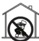
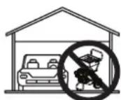
NEVER use inside a home or garage, EVEN IF doors and windows are open.


Only use OUTSIDE and far away from windows, doors, and vents.

WARNING
READ AND UNDERSTAND ALL IN
STRICTIONS. Failure to follow all instructions listed below and on the machine may result in electric shock, fire, and/or serious personal injury.
- Read the user manual carefully. Learn its applications and limitations, as well as the specific potential hazards related to this tool. Following this rule will reduce the risk of electric shock, fire, or serious injury.
- Retain these instructions. Refer to them frequently and use them to instruct others who may use this tool.
IMPORTANT SAFETY INSTRUCTIONS

DANGER
Wood chipper / shredder exhausts carbon monoxide (CO), an invisible, very poisonous gas. If you smell exhausting carbon monoxide. But, even if you sometimes you may be inhaling CO.
ONLY operate the unit outside, in a well-ventilated area. NEVER operate the unit indoors, doing so CAN KILL YOU IN MINUTES.
- Correct Use - Only use the unit outside and downwind, far away from windows, doors and vents. Always direct exhaust away from occupied spaces. Always install battery-powered carbon monoxide detectors or plug-in carbon monoxide detectors with battery back-up in living areas. See Figure 1.
- Incorrect Use - NEVER use a wood chipper / shredder in the home, garage, basement, attic, crawl space or any other fully or partially enclosed area. Areas such as these can allow dangerous levels of carbon monoxide to accumulate. An open door or a running fan WILL NOT provide adequate ventilation. See Figure 2.
If feeling dizzy, weak, or sick while using the unit, move to fresh air immediately. Contact a doctor. This may be carbon monoxide poisoning.

WARNING
Become familiar with all the instruc
tions, safety warnings, illustrations, and specifications provided with this product. Failure to follow the manufacturer's instructions may result in electric shock, fire, and/or carbon monoxide poisoning that can lead to death or serious injury.
NOTICE
Install battery-powered carbon monoxide
detectors or plug-in carbon monoxide detectors with battery back-up in living areas.
- This product should ONLY be used outdoors.
- NEVER use the unit in the home, garage, basement, attic, crawl space or any other fully or partially enclosed area. Areas such as these can allow dangerous levels of carbon monoxide to accumulate. Carbon monoxide (CO), an invisible, odorless, and extremely poisonous gas CAN KILL YOU IN MINUTES.
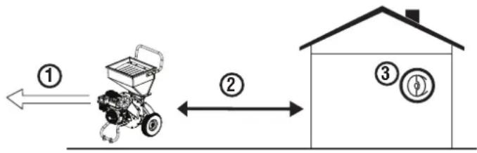
FIG.1
1 - Exhaust (CO)
2 - Only use OUTSIDE and FAR AWAY from windows, doors, and vents
3 - CO detectors in living areas
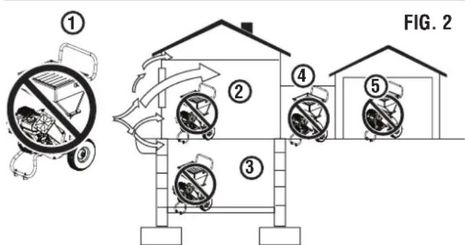
1 - Exhaust (CO)
2-Living area
3 - Basement crawlspace
4-Entryway/Porch/Mudroom
5-Garage
- Only use OUTSIDE and far away from windows, doors, and vents as recommended by the US Department of Health and Human Services Centers for Disease Control and Prevention. Specific homes and/or wind conditions may require additional distance.
- Never expose the unit to rain, snow, water spray, or standing water while in use. Store and operate the unit in a dry or covered (but not enclosed) location.
- Do not let children or untrained individuals operate the unit.
- Keep children, bystanders, and pets a minimum of 10 ft. away from a unit in operation.
- Maintain Safe Distance. While operating and storing, keep at least five feet of clearance on all sides of the unit, including overhead. Turn the unit off and allow it to cool a minimum of 30 minutes before storage. Heat created by the muffler and exhaust gases could be hot enough to cause serious burns and/or ignite combustible objects.
- Do not operate the unit in areas where combustible or hazardous materials are stored including gasoline and natural gas filling stations.
- Do not operate the unit while barefoot, with wet hands or feet, while standing in water or in wet conditions.
- Do not use this unit when tired or under the influence of drugs, alcohol, or medication.
-
Burn Hazard. Do not touch hot surfaces.
-
Do not contact the muffler or engine. They are very HOT and will cause severe burns. Do not put body parts or any flammable or combustible materials in the direct path of the exhaust.
- Keep hands, fingers, feet, and other body parts away from all moving parts of the unit.
- Do not operate the unit on an incline. The unit should always be placed on a flat stable surface.
- Inspect the physical condition of the product prior to each use. Look for loose bolts, fluid leaks, and other signs of wear. Replace all damaged items. For replacement parts or assistance, contact our customer service team.
- For optimal performance, use the unit in temperatures between 23^(-5^) and 104^(40^) with a maximum relative humidity of 90% .
- Before starting the unit, check all fluids (oil and gasoline).
- Do not remove the oil dipstick or fuel cap while the unit is in operation.
- Securely tighten the oil dipstick after adding oil and the fuel cap after adding gasoline.
- Avoid skin contact with engine oil or gasoline. Wear protective clothing and equipment. Wash all exposed skin with soap and water. Prolonged skin contact with gasoline or engine oil may cause severe skin irritation and other adverse reactions.
- Before transporting the unit, disconnect the spark plug boot, drain the fuel tank and properly restrain the unit.
- Fuel or oil may leak from the unit during transport. Place a towel, plastic sheet, or absorbent pad beneath the unit to protect the transportation vehicle.
- To prolong the life of this product, follow the instructions in the Maintenance section of this manual.
- Replace damaged or worn items with recommended or equivalent replacement parts. Using an incorrect or incompatible part might create a hazard that could result in serious personal injury.
- Always remove any tools or other service equipment used during maintenance away from the unit before operating.
SAFETY PRECAUTIONS FOR GASOLINE AND GASOLINE VAPOR

DANGER
Fire and explosion hazard. Gasoline
is highly explosive and flammable and can cause severe burns or death.

WARNING
Fire and Burn Hazard. NEVER loosen
or remove the fuel cap while the unit is in operation. Turn the unit off and allow it to cool for at least five minutes before adding gasoline. Loosen the fuel cap slowly.

WARNING
In case of a gasoline fire, do not at-
tempt to extinguish the flame unless the engine/fuel control switch is in the OFF position. Introducing an extinguisher to the unit with an open fuel switch could create an explosion hazard.
- Fire Hazard. Gasoline is highly flammable. Handle with care.
- Never use gasoline as a cleaning agent.
Gasoline is a skin irritant and needs to be cleaned up immediately if it comes in contact with the skin. - Do not store gasoline near furnaces, water heaters, or any other appliances that produce heat or have automatic ignitions.
- Keep gasoline away from sparks, open flames, pilot lights, heat, and other sources of ignition.
- Store any containers containing gasoline in a well-ventilated area, away from any combustibles or source of ignition.
- ALWAYS store gasoline in a container approved for gasoline. Unapproved containers can break or deteriorate allowing gasoline or gasoline vapors to escape which can create a serious hazard.
Gasoline has a distinctive odor, this will help detect potential leaks quickly.
Gas vapors can cause a fire if ignited. - Do not smoke when handling fuel, adding fuel to the unit, or emptying the gas tank.
- Wear eye protection while refueling.
- Before adding fuel to the unit, turn the unit off and allow it to cool a minimum of five minutes. If necessary, move the unit to level ground.
- Do not remove the fuel tank cap when the unit is in operation.
- Loosen the fuel cap slowly to safely release pressure, keep gasoline from escaping around the cap, and to avoid the heat from the muffler igniting fuel vapors.
- NEVER fill the gasoline tank beyond the maximum fill ring on the fuel screen. Keeping gasoline levels at or below the fill ring will allow for fuel expansion. Overfilling the fuel tank can result in a sudden overflow of gasoline and result in spilled gasoline coming in contact with HOT surfaces.
- Spilled fuel can ignite. Wipe up spills immediately and allow area to dry before operating the unit. NEVER attempt to burn off spilled fuel.
- Securely tighten the fuel cap after adding gasoline.
- Do not cover the fuel cap while the unit is in operation. Covering the cap may cause the engine to fail or damage the product.
- Drain fuel before storing the unit. Store the unit and the fuel separately in well-ventilated areas away from sparks, open flames, pilot lights, heat, and other sources of ignition.
- Turn the unit off and allow it to cool a minimum of 30 minutes before draining fuel.
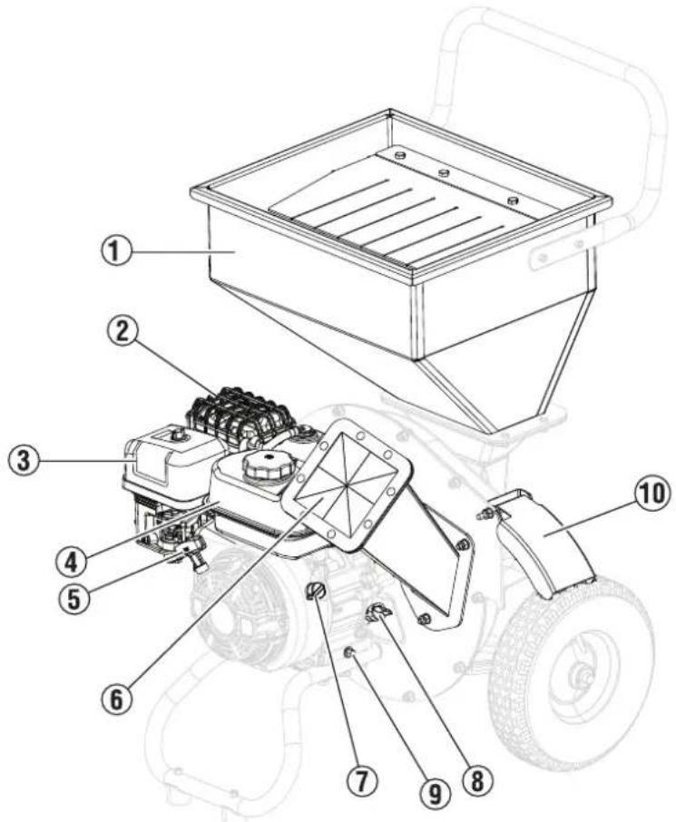
FIG. 3
UNDERSTANDING THE TOOL
To reduce the risk of personal injury and product failure, read and understand the information in this user manual and the information on the product labeling. See Figure 3 and the Component table for more information.
| Components | ||
| Index Number | Component Description | |
| 1 Hopper | Insert materials into the hopper for shredding. | |
| 2 Muffler | The muffler releases exhaust from the unit and is hazardous while the unit is hot and in operation. | |
| 3 Air filter | The air filter captures debris and restricts materials from being drawn into the engine. | |
| 4 Fuel tank | The fuel tank has a 0.95 gal (3.6 L) capacity for unleaded gasoline. | |
| 5 Recoil handle | Handle Use the recoil handle to start the unit. | |
| 6 Chipper / Shredder chute Put items in the chipper / shredder chute for proper operation. | ||
| 7 Engine ON / OFF switch Use the Engine ON / OFF switch to start or end operation. | ||
| 8 Oil dipstick Use the oil dipstick to check the oil level of the unit. | ||
| 9 Oil drain plug Use the oil drain plug to drain oil from the unit when changing the oil. | ||
| 10 Discharge port cover The discharge port cover is intended to provide an additional layer of user protection from material being discharged through the chipper chute. Be sure to follow all of the safety instructions listed in this user manual. Discharged materials from the unit can cause serious personal injury or death. | ||
REMOVING CARTON CONTENTS
WARNING This product requires assembly. Do not attempt to operate this product if any items in the INCLUDED LIST are already assembled when removing the carton contents. These items are not assembled by the manufacturer and should require customer assembly. Using an improperly assembled product can be hazardous and could result in serious personal injury.
- Remove and inspect the carton contents. Confirm that all the items in the INCLUDED LIST are present and undamaged.
| INCLOSED LIST | |
| ITEM QUANTITY | |
| Bolt (M8x16mm) 4 | |
| Hopper plate 1 | |
| Hopper 1 | |
| Hopper cover 1 | |
| Hopper gasket 1 | |
| Bolt (M6x16mm) 11 | |
| Nut (M6) 11 | |
| Handle 1 | |
| Discharge port cover 1 | |
| Delta knob 1 | |
| Nut (M8) 8 | |
| Wheel 2 | |
| Flat washer 2 | |
| Cotter pin | 2 |
| Support stand | 1 |
| Bolt (M8x65mm) 4 | |
| Split washer | 4 |
| Flat washer | 4 |
| Collection bag | 1 |
| Rod | 1 |
| Locking pin | 2 |
| Chipper chute | 1 |
| Funnel | 2 |
| Spark plug tool | 1 |
| 8 mm / 10 mm combo wrench | 1 |
| 10 mm / 13 mm combo wrench (120 mm) | 1 |
| 10 mm / 13 mm combo wrench (200 mm) | 1 |
If any parts are missing, contact customer service at service@wpowereq.com or call 1-855-944-3571.
WARNING Do not alter or modify this product unless instructed otherwise in this manual or by the manufacturer. Do not use attachments or accessories that are not recommended for use with this product. Making unauthorized modifications and using incompatible accessories can damage the unit and may void the warranty.
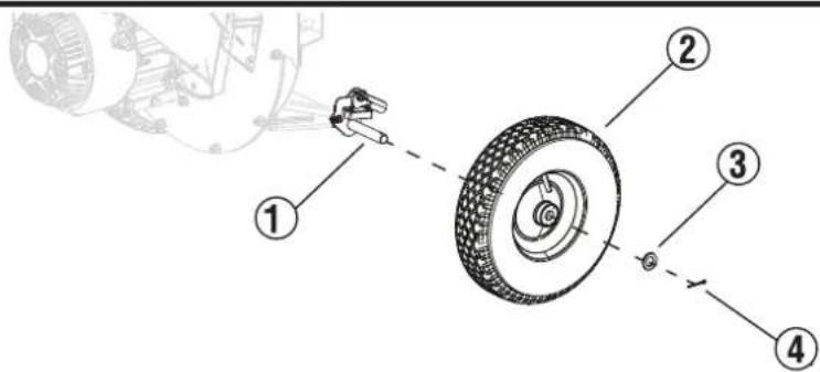
FIG. 4
INSTALLING THE WHEELS
- See Figure 4. Attach the wheel (2) to the axle assembly (1) on the motor housing.
- Put the flat washer (3) on the axle assembly and secure with the cotter pin (4).
- Repeat Step 1-2 for the other wheel.
INSTALLING THE SUPPORT STAND
- See Figure 5. Attach the support stand (2) to the motor housing.
- Align the holes on the support stand with the holes underneath the motor housing (5) and attach the split washer (6), flat washer (3) and bolt (1) to the support stand.
- Secure the bolt to the support stand with the nut (4). Torque to 22 N m (16.2 ft lb). Repeat for all of the bolts and nuts.
FIG.5
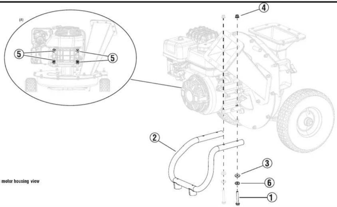
A - Underneath the motor housing view
INSTALLING THE HOPPER
- See Figure 6. Attach the hopper gasket (3) to the motor housing (4).
- Put the hopper (2) on the hopper gasket and motor housing. Be sure that the holes are aligned.
- Secure the hopper to the motor housing with the bolt (1) and nut (5). Torque to 10 N m (7.3 ft lb). Repeat for all of the bolts and nuts.
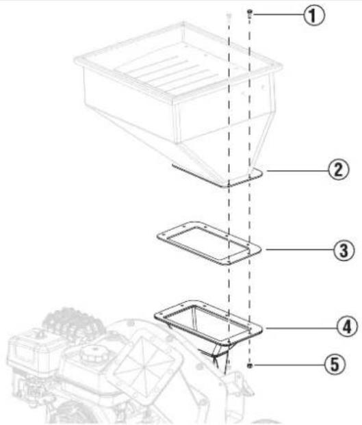
FIG.6
INSTALLING THE DISCHARGE PORT COVER
- See Figure 7. Put the discharge port cover (2) on the motor housing and secure the knob (1).
- Secure the discharge port to the motor housing with the nut (3). Torque to 22Nm (16.2 ft lb).
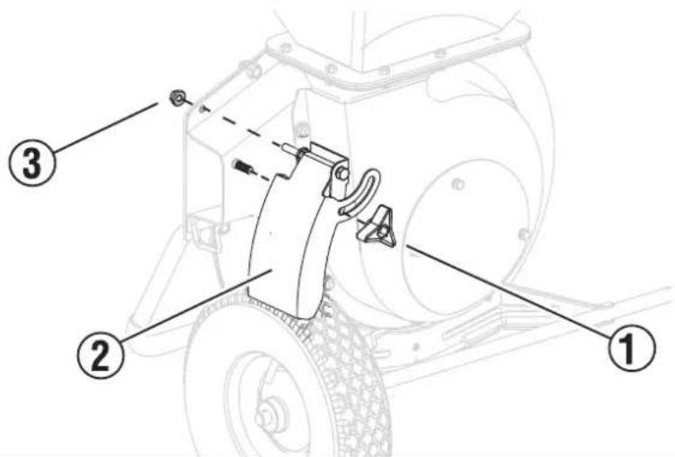
FIG. 7
INSTALLING THE HANDLE
- See Figure 8. Attach the handle (2) to the hopper. Be sure that the holes in the handle are aligned with the holes in the hopper.
- Secure the handle to the hopper with the bolts (1) and nut (3). Torque to 12 N m (8.9 ft lb). Repeat for all of the bolts and nuts.
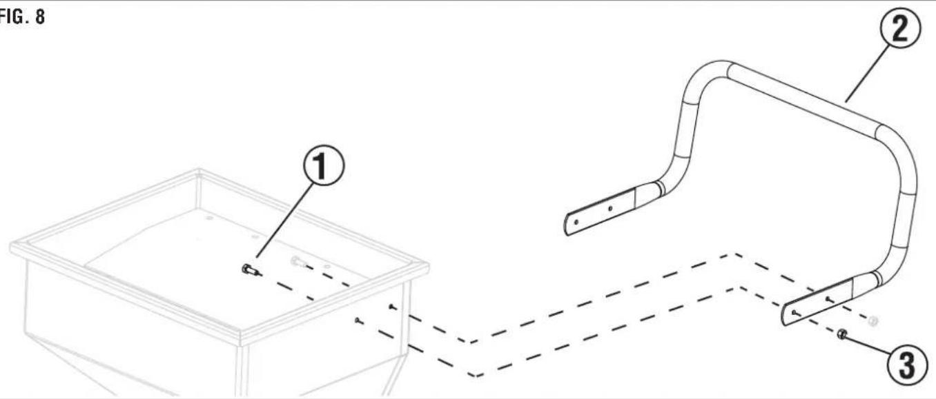
FIG. 8
INSTALLING THE CHIPPER CHUTE
- See Figure 9. Attach the chipper chute (1) to the bolt (2) on the frame of the motor housing.
- Secure the chipper chute to the bolts on the motor housing with the nut (3). Torque to 22 N m (16.2 ft lb).
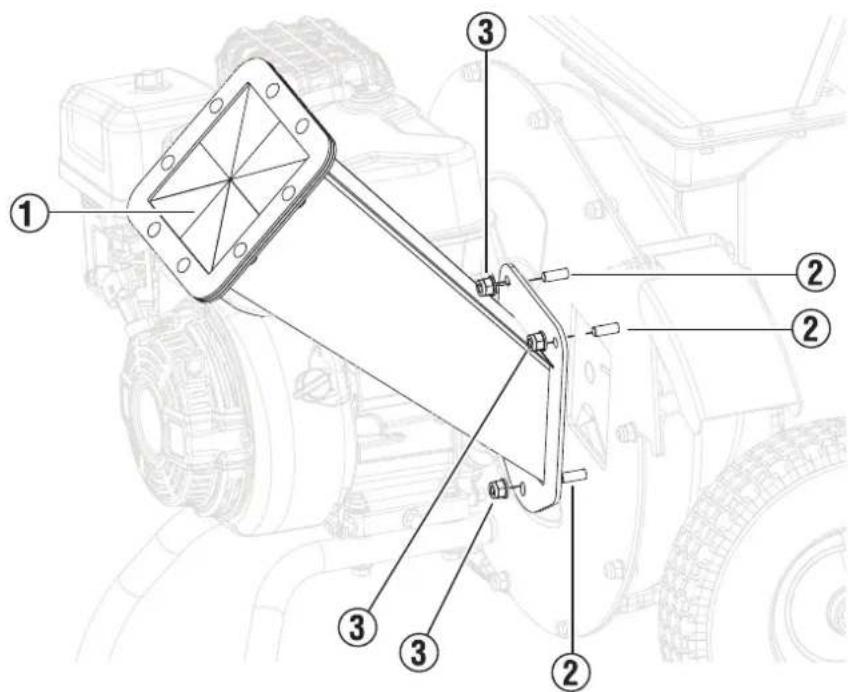
FIG.9
INSTALLING THE PRESS PLATE
- See Figure 10. Attach the hopper cover (2) and press plate (1) to the hopper (3).
- Secure the hopper cover and press plate to the hopper with the bolts (4). Torque to 12Nm (8.9 ft lb).
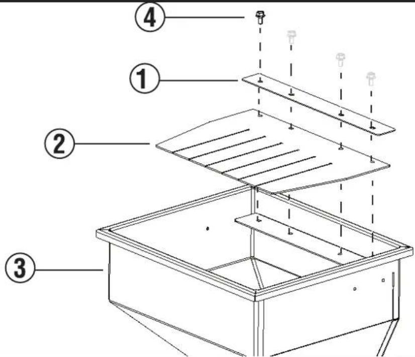
FIG. 10
INSTALLING THE COLLECTION BAG
- Locate the collection rod hanging mount, on the front of the unit, underneath the location of the hopper.
- Attach the collection hanging rod to the collection rod hanging mount and secure with the locking pin.
NOTE: Be sure to use the end of the collection hanging rod with the notches to secure the collection hanging rod to the collection rod hanging mount.
- Attach the collection bag to the collection hanging rod, with the opening towards the unit.
- After attaching all the loops of the collection bag to the collection hanging rod, secure the collection bag to the collection hanging rod with the locking pin.
- Put the opening of the collection bag over the discharge port entirely. Be sure to secure the collection bag over the discharge port by pulling the draw strings.
WARNING Always wear eye protection with side shields marked to comply with ANSI Z87.1. Failure to do so could result in objects being thrown into your eyes resulting in possible serious injury.
WARNING Do not use any attachments or accessories not recommended by the manufacturer of this product. The use of attachments or accessories not recommended can result in serious personal injury.
NOTICE Before each use, inspect the entire product for damaged, missing, or loose parts such as nuts, bolts, caps, etc. Tighten securely all fasteners and caps and do not operate this product until all missing or damaged parts are replaced. Please contact customer service.
DANGER Exhaust contains high levels of carbon monoxide (CO), an invisible, odorless, and extremely poisonous gas. If you smell exhaust fumes, you are breathing carbon monoxide. But, even if you do not smell exhaust fumes you may be inhaling CO.
ONLY operate the unit outside, in a well-ventilated area. NEVER operate the unit indoors, doing so CAN KILL YOU IN MINUTES.
- Correct Use - ONLY use the unit outside and downwind, far away from windows, doors and vents. ALWAYS direct exhaust away from occupied spaces. ALWAYS install battery-powered carbon monoxide detectors or plug-in carbon monoxide detectors with battery back-up in living areas. See Figure 1.
- Incorrect Use - NEVER use the unit in a home, garage, basement, attic, crawl space or any other fully or partially enclosed area. Areas such as these can allow dangerous levels of carbon monoxide to accumulate. An open door or a running fan WILL NOT provide adequate ventilation. See Figure 2.
If feeling dizzy, weak, or sick while using the unit, move to fresh air IMMEDIATELY. Contact a doctor. This may be carbon monoxide poisoning.
WARNING Do not alter or modify this product unless instructed to so in this manual or by the manufacturer. Do not use attachments or accessories that are not recommended for use with this product. Making unauthorized modifications and using incompatible accessories can damage the unit and may void the warranty.
WARNING Avoid skin contact with engine oil or gasoline. Wear protective clothing and equipment. Wash all exposed skin with soap and water. Prolonged skin contact with gasoline or engine oil may cause severe skin irritation and other adverse reactions.
NOTICE Inspect the physical condition of the product prior to each use. Look for loose bolts, fluid leaks, and other signs of wear. Replace all damaged items.
KNOW HOW TO SAFELY LOCATE AND OPERATE THE UNIT
DANGER Asphyxiation hazard. Place the unit in a well-ventilated area. DO NOT place the unit near vents or intakes where exhaust fumes could be drawn into occupied or confined spaces. Carefully consider wind and air currents when positioning the unit.
WARNING Electrocution hazard. Never use the unit in a location that is wet or damp. Never expose the unit to rain, snow, water spray, or standing water while in use. Protect the unit from all hazardous weather conditions.
WARNING Fire hazard. Only operate the unit on a solid, level surface. Operating the unit on a surface with loose material such as sand or grass clippings can cause debris to be ingested by the unit that could block cooling vents or the air intake system. Allow the unit to cool for 30 minutes before transport or storage.
lead and understand all safety information before starting the unit.
- NEVER use the unit in the home, garage, basement, attic, crawl space or any other fully or partially enclosed area. Areas such as these can allow dangerous levels of carbon monoxide to accumulate. Carbon monoxide (CO), an invisible, odorless, and extremely poisonous gas CAN KILL YOU IN MINUTES.
- DO NOT operate the unit in the back of a SUV, camper, trailer, truck bed (regular, flat, or otherwise), under stairs, next to walls or buildings, or in any other location that will not allow for adequate cooling of the unit and/or the muffler. Operating the unit in enclosed or partially enclosed areas will allow dangerous levels of CO to accumulate.
- Do not operate the unit on an incline. The unit should always be placed on a flat stable surface.
- The unit should be on a flat, level surface at all times (even while not in operation).
- The unit must have at least 5 ft. (1.5 m) of clearance from all combustible material.
ADDING OIL/CHECKING OIL LEVEL
NOTICE Do not attempt to crank or start engine before it has been properly serviced with recommended oil. Failure to add engine oil before starting will result in serious engine damage that is not covered under warranty.
NOTICE Use of 2-stroke/cycle oil or other unapproved oil types can cause severe engine damage that is not covered under warranty.
The recommended oil type for typical use is 10W-30 engine oil (not included). If operating the unit in extreme temperatures, refer to the following chart.
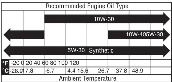
NOTE: Check the engine oil level before each use or every 8 hours of operation.
- Turn the unit off and allow the engine to cool for at least five minutes.
- Place the unit on a level surface in a well-ventilated area.
- Clean the area around the oil dipstick.
For initial oil fill:
- Slowly unscrew and remove the oil dipstick.
See Figure 11. Use the funnel (included) and slowly pour engine oil into the oil fill hole. Check the level frequently to be sure not to overfill.
NOTE: The unit was functionally tested in the factory and may contain minimum residual oil. Additional oil is required to operate the unit. Do not overfill.
Place and tighten the oil dipstick.
To check oil level:
- Slowly unscrew and remove the oil dipstick.
- Clean the dipstick and re-seat it inside the oil fill hole. Do not thread the dipstick.
- Remove the dipstick and confirm that the oil level is within safe operating range.
See Figure 12. If the oil level is low, add recommended engine oil incrementally and recheck until the level is within the safe operating range (1). - Secure the oil dipstick and hand-tighten.
GASOLINE REQUIREMENTS
NOTICE
Do not use E15 or E85 fuel in this product.
Engine or equipment damage caused by stale fuel or the use of unapproved fuels (such as E15 or E85 ethanol blends) is not covered by warranty. Only use unleaded gasoline containing up to 10% ethanol.
- ALWAYS use CLEAN, FRESH, unleaded gasoline (87-93 octane) in this unit. NEVER use OLD, STALE, or CONTAMINATED gasoline.
- Up to 10% ethanol (gasohol) is acceptable (where available; non-ethanol fuel is recommended).
DO NOT use E85 or E15.
DO NOT use a gas oil mix.
DO NOT modify the engine to run on alternate fuels.
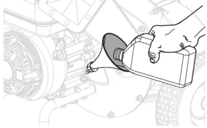
FIG. 11
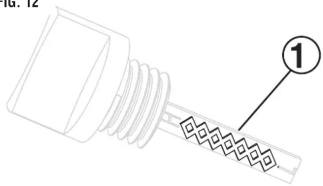
FIG. 12
USING FUEL STABILIZER
Adding a fuel stabilizer (not included) extends the usable life of fuel and helps prevent deposits from forming that can clog the fuel system. Follow the manufacturer's instructions for use.
Always mix the correct amount of fuel stabilizer to gasoline in an approved gasoline container before fueling the unit. Run the unit for five minutes to allow the stabilizer to treat the entire fuel system.
ADDING GASOLINE

DANGER
move the fuel cap or refuel the unit while the engine is running. Do not smoke or create sparks while fueling. Always turn the engine off and allow the unit to cool for at least five minutes before refueling.

DANGER
overfill fuel tank. Fill only to the red maximum fill ring on the fuel screen. Overfilling may cause fuel to spill onto engine causing a fire or explosion hazard.

WARNING
oline tank, or any other fuel item that is broken, cut, torn or damaged.
NOTICE
Only fill the tank from an approved gasoline
container. Be sure the gasoline container is internally clean and in good condition to prevent fuel system contamination.
- Turn the unit off and allow the engine to cool for at least five minutes.
- Place the unit on a level surface in a well-ventilated area. DO NOT fuel indoors.
- See Figure 14. Clean area around fuel cap (1) and remove the cap slowly.
- See Figure 13. Slowly add the recommended fuel. Do not overfill.
NOTE: See Figure 14. The gasoline level should NOT be higher than the red maximum fill ring (2) on the fuel screen.
5. Install the fuel cap. Tighten securely.
6. Clean up any spilled fuel.
7. Move at least 30 ft. away from refueling area before restarting the engine.
NOTICE
Fuel can damage paint and plastic. Use cau
tion when filling the fuel tank. Damage caused by spilled fuel is not covered under warranty.
NOTICE
Clean the fuel screen filter (3) of debris be
fore and after each fueling. Remove the fuel screen filter by slightly compressing it while removing it from the fuel tank.
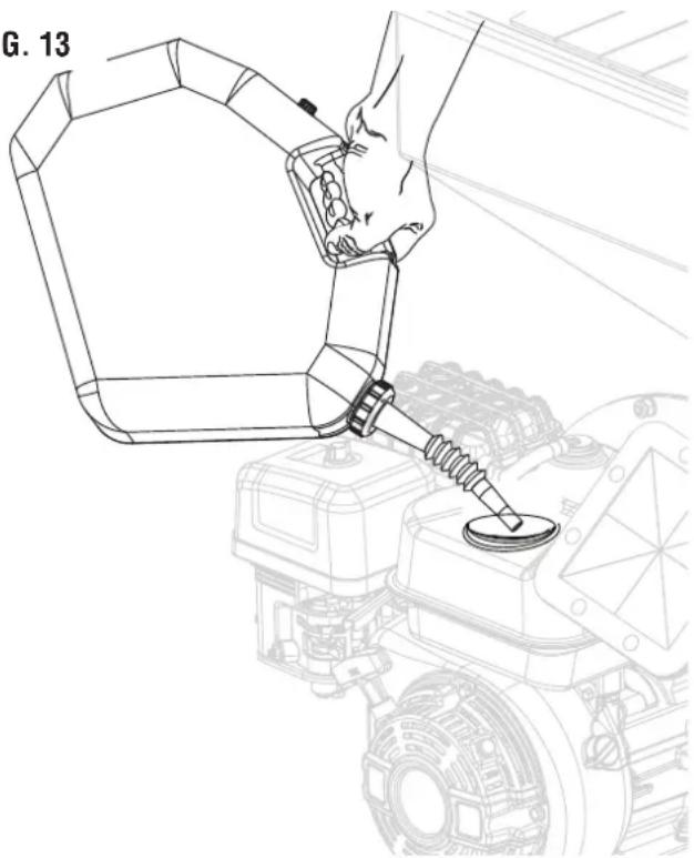
FIG. 13
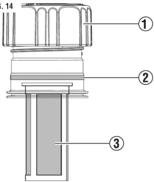
FIG. 14
BREAK-IN PERIOD
For proper break-in, do not apply a heavy load or operate the engine at maximum speed during the first three hours of operation.
Do not use full synthetic oil during break in period. Full synthetic oil may prevent proper breaking and seating of the piston rings.
Engine power is reduced the higher the unit is operated above sea level. Output will be reduced approximately 3.5% for every 1,000 feet of increased altitude from sea level.
High altitude adjustment is required for operation at altitudes over 8,000 ft. Operation without this adjustment will cause decreased performance, increased fuel consumption, and increased emissions.
To purchase the high altitude kit, P/N 518059-01, please visit parts.wpowereg.com.
High Altitude Kit P/N $18059-01
NOTICE
DO NOT operate the unit at altitudes below
2,000 ft. (762 m) with the high altitude kit installed. Engine damage may occur.
STARTING THE ENGINE

DANGER
Fire and explosion hazard. DO NOT
move or tip the unit during operation.

WARNING
Confirm that the area around the unit
is clear before starting the unit.
- Confirm that fuel is in the gas tank.
- See Figure 15. Engage the wheel locks on both wheels.
- See Figure 16. To start a cold engine, move the choke lever to the START position. To restart a warm engine, keep the choke lever in the RUN position.
- See Figure 17. Turn the fuel tank valve to the ON position.
- Move the speed control lever away from the SLOW position.
- Turn the Engine ON/OFF switch to ON.
- Firmly grasp and pull the recoil handle slowly until there is increased resistance, then pull rapidly.
- Allow the engine to run for several seconds. Then, if the choke lever is in the START position, move the choke lever very slowly to its RUN position.
NOTE: Moving the choke lever too quickly could stall the engine.
NOTE: Allow the engine to run at no load for five minutes after every start-up to allow the engine to stabilize.
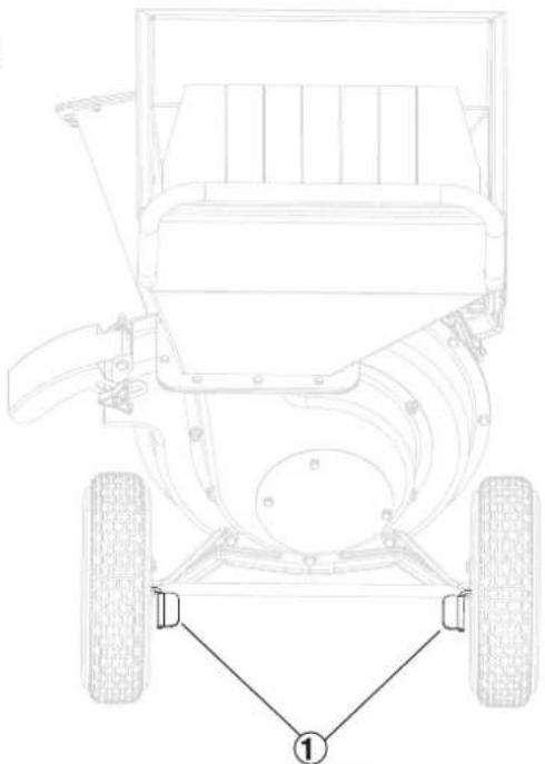
FIG. 15
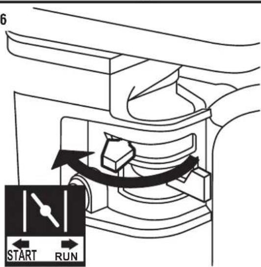
FIG. 16
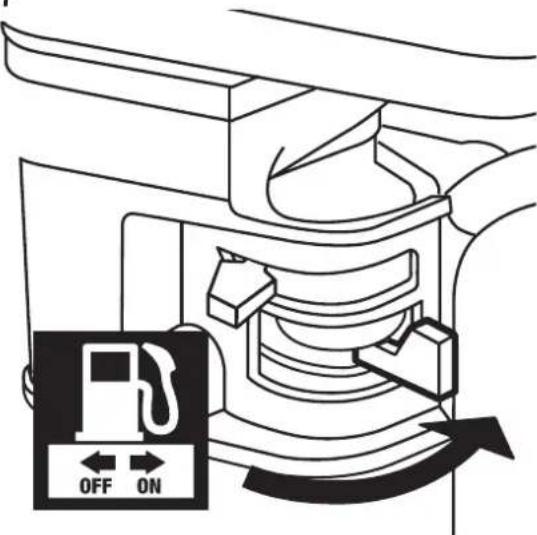
FIG. 17
CHIPPING AND SHREDDING
WARNING To prevent serious injury, do not force the chipper/shredder. Items cannot be thicker than 0.5 in. for the hopper and items cannot be thicker than 3 in. for the chipper chute. Do not force items into the machine. The chipper/shredder is designed to draw materials at the proper rate.
WARNING Never use hands or any other body parts to draw materials directly into the shredder. If necessary, use a stick to push materials into the shredder.
- Without putting your hands into the shredder (on top), slowly drop material into the hopper (one branch at a time). The machine will pull the material in automatically.
- The chipper chute is located on the side of the unit; only feed one branch in at a time, with the larger end first.
- Material discharges from the discharge port at high speed. Be sure the discharge bag is properly attached before use. Do not operate the chipper / shredder without the collection bag in place.
- Do not allow the collection bag to overfill with processed material. This may prevent proper discharge and can result in the kickback of material. Empty the collection bag periodically, as needed.
Note: If the chipper / shredder becomes clogged during use, immediately turn off the engine. Wait until the unit stops completely. Disconnect the spark plug. Unclog the unit by shifting the material with a long stick.
STOPPING THE ENGINE
- Slide the Speed Control Lever to the SLOW position.
- Turn the Engine ON / OFF switch to OFF.
- Close the fuel valve.
To stop the unit quickly in an emergency:
- Turn the Engine ON / OFF switch to OFF.
CLEANING AND STORING THE UNIT
After every use, and before storing the unit, clean debris from the machine.
- Remove the spark plug boot from the spark plug.
- Allow the engine to completely cool down.
See Figure 18. Remove the bolts (1) from the hopper / rotor housing cover.
Clear all of the debris from the hopper / rotor housing and discharge port.
- Put the hopper / rotor housing cover on the unit and secure with the nuts. Torque to 22Nm (16.2 ft lb).
- Store the chipper / shredder in a dry indoor location away from children.
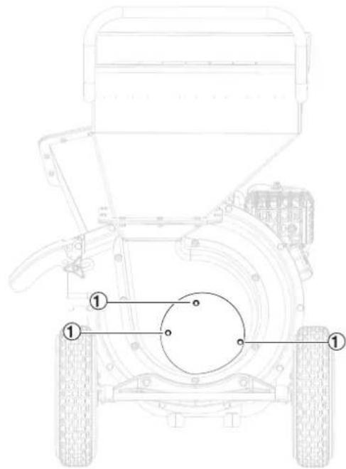
FIG. 18

WARNING
Always wear eye protection with side shields marked to comply with ANSI Z87.1. Failure to do so could be thrown into your eyes resulting in possible serious injury.

WARNING
Use only authorized replacement parts. Use of any other parts can create a hazard or cause product dam

WARNING
To prevent serious injury from accidental starting, turn the Engine ON / OFF switch to OFF, wait for the end disconnect the spark plug cap before performing any inspection, maintenance, or cleaning procedures.

WARNING
To prevent serious injury from equipment failure, do not use the unit if it is damaged. If there is an abnormal excess smoking from the unit, contact customer service.
NOTICE
Periodically inspect the entire product for damaged, missing, or loose parts such as nuts, bolts, and caps. Tight and caps. Do not operate this product until all missing or damaged parts are replaced. Please contact customer tance.
MAINTENANCE SCHEDULE
Regular maintenance will improve performance and extend the service life of the unit. Follow the hourly or calendar intervals, whichever occurs first. More frequent service is required when operating in adverse conditions as noted below.
| Before Each Use | After First 25 Hours or First Month | Every 50 Hours or Every Six Months | Every 100 Hours or Every Six Months | Every 300 Hours or Every Year | |
| Check Engine Oil | X | ||||
| Change Engine Oil1 | X | X | |||
| Clean Air Filter2 | X | ||||
| Inspect/Clean Spark Plug | X | ||||
| Replace Spark Plug | X | ||||
| Inspect/Replace Chipping Blades | X | ||||
| Inspect/Replace Shredding Hammers | X | ||||
| Inspect Chipper Chute, Hopper, and Discharge Port Cover | X | ||||
| Replace Air Filter | X | ||||
| Check/Adjust Valve Clearance3 | X | ||||
| Clean Fuel Tank, Strainer, and Carburetor3 | X | ||||
| Replace Fuel Line, if necessary3 | X | ||||
| 1 Change oil every month when operating under heavy load or in high temperatures.2 Clean more often under dirty or dusty conditions. Replace air filter if it cannot be adequately cleaned.3 To avoid potential personal injury or damage to the unit, it is recommended that the maintenance task be performed at a Westinghouse approved service center (not covered by warranty). | |||||
GENERAL MAINTENANCE
Avoid using solvents when cleaning plastic parts. Most plastics are susceptible to damage from various types of commercial solvents and may be damaged by their use. Use clean cloths to remove dirt, dust, oil, and grease.

WARNING
Do not let brake fluids, gasoline, petroleum-based products, or penetrating oils contact plastic parts.
Chemicals can damage, weaken, or destroy plastic which can result in serious personal injury.

CAUTION
Always clean the tool after each use. Failure to clean the tool can result in damage or result in poor per
formance.

CAUTION
Never use a water hose to clean the tool.
CLEANING THE UNIT
Do not store or operate the unit in dirty, dusty, or corrosive environments. Do not allow foreign materials and debris to clog the vents on the unit.
NEVER clean the unit with a garden hose. Water can damage the fuel system. If the unit needs to be cleaned, use a soft brush and damp cloth to clean the exterior and use low pressure air (no greater than 25 psi) to clean the vents.
Never use gasoline as a cleaning agent.
CLEANING/ REPLACING THE AIR FILTER
Keep the air filter clean. A dirty air filter can cause poor performance and decrease the service life of the product. NEVER operate the unit without an air filter in place.
- Turn the unit off and allow the engine to cool for 30 minutes.
- Remove the air filter from the air cleaner housing and place it in a suitable cleaning container. Replace the air filter if damaged.
- Wash the air filter by submerging the filter in a solution of household detergent soap and warm water. Slowly squeeze the filter to thoroughly clean.
NOTICE
DO NOT twist or tear the air filter during cleaning or drying. Only apply slow but firm squeezing action.
- Rinse the air filter by submerging it in fresh water and applying a slow squeezing action. Allow the filter to dry thoroughly.
NOTICE
Do not pollute. Follow the guidelines of the EPA or other governmental agencies for proper disposal of hazardous
materials. Consult local authorities or reclamation facility.
- Dip the air filter in clean engine oil then squeeze out all excess oil. The engine will smoke when started if too much oil is left in the filter.
- Install the air filter in the air cleaner housing and install the air filter cover.
CHANGING THE ENGINE OIL
For optimal performance, change the engine oil according to the figures specified in the maintenance schedule or the engine manual (if applicable). When using the unit under extreme, dirty, dusty conditions or in extremely hot weather, change the oil more frequently. NOTE: Change the oil while the engine is warm but not hot. Warm engine oil drains more quickly and thoroughly than cool oil. Contact with hot oil will cause serious burns.
- Turn the unit off and allow the engine to cool for 30 minutes.
- Place the unit on a level surface in a well-ventilated area.
- Close the fuel valve.
- Clean the area around the oil dipstick and drain bolt.
- Slowly unscrew and remove the oil dipstick.
- Place an oil pan (or suitable container) under the unit.
- Remove the drain bolt.
After the oil has drained completely, secure the drain bolt. - Refill the oil.
Clean the oil dipstick. - Secure the oil dipstick and hand-tighten.
- Clean any spilled oil.
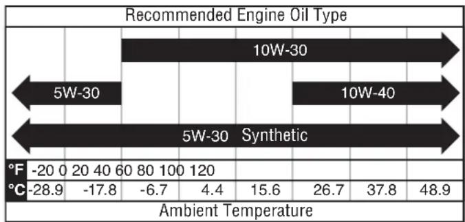
CLEANING/ REPLACING THE SPARK PLUG
NOTICE ALWAYS use the Westinghouse OEM or compatible non-resistor-type spark plug. Use of resistor-type spark plug can result in rough idling, misfire, or may prevent the engine from starting.
Be sure the spark plug is clean and properly gapped. To clean or replace the spark plug:
- Turn the unit off and allow the engine to cool for 30 minutes.
- Place the unit on a level surface in a well-ventilated area.
- See Figure 19. Remove the spark plug boot (1) by firmly pulling the spark boot directly away from the engine.
- Clean the area around the spark plug (2).
- Remove the spark plug with the included spark plug socket wrench.
NOTICE Never apply any side load or move the spark plug laterally when removing the spark plug.
- Inspect the spark plug. Replace if electrodes (4) are pitted, burned, or the insulator (3) is cracked. Only use a recommended replacement plug.
Measure the spark plug electrode gap with a wire-type feeler gauge. If necessary, correct the gap by carefully bending the side electrode.
Spark plug gap: 0.024 - 0.032 in. (0.60 - 0.80 mm)
- Carefully install the spark plug finger tight, then tighten as additional 3/8 to 1/2 turn with the spark plug wrench.
Install the spark plug boot.
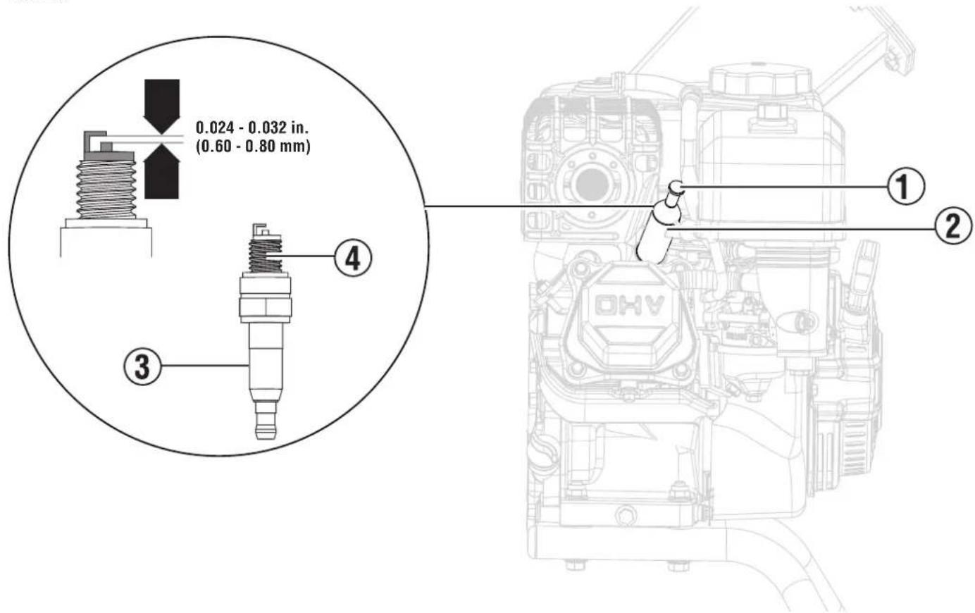
FIG. 19
DRAINING THE FUEL TANK AND CARBURETOR FLOAT BOWL

WARNING
ALWAYS store gasoline in a container approved for gasoline. Unapproved containers can break or deteriorate gasoline vapors to escape which can create a serious hazard.
Even properly stabilized fuel can leave residue and cause corrosion if left long term. If storing the unit for two to six months, drain the float bowl to prevent gum and varnish buildup in the carburetor. If storing the unit for longer than six months, drain the fuel tank to prevent fuel separation, deterioration, and deposits in the fuel system.
- Turn the unit off and allow the engine to cool for 30 minutes.
- Place the unit on a level surface in a well-ventilated area.
To drain the float bowl:
- Locate the drain bolt near the bottom of the carburetor float bowl.
- Prepare an approved gasoline container to catch the drained fuel.
- Loosen the float bowl drain bolt and allow the fuel to drain. Tighten the float bowl drain bolt.
To run the float bowl dry:
- Turn the fuel tank valve to the ON position.
- Start the unit.
- Turn the fuel tank valve to the OFF position.
- Allow the unit to run until the fuel in the carburetor is depleted and the engine stops.
- Turn the engine switch to the OFF position
To drain the fuel tank:
NOTICE
To prevent damage to the unit, drain the engine oil before emptying the fuel tank. See Changing the engine oil
- Turn the fuel shut-off valve to the off position.
- Clean area around fuel cap and remove the cap slowly.
- Remove the fuel screen filter by slightly compressing it while removing it from the tank.
- Using a commercially available gasoline hand pump (not included), siphon the gasoline from the fuel tank into an approved gasoline container. DO NOT use an electric pump.
REPLACING THE CARBURETOR
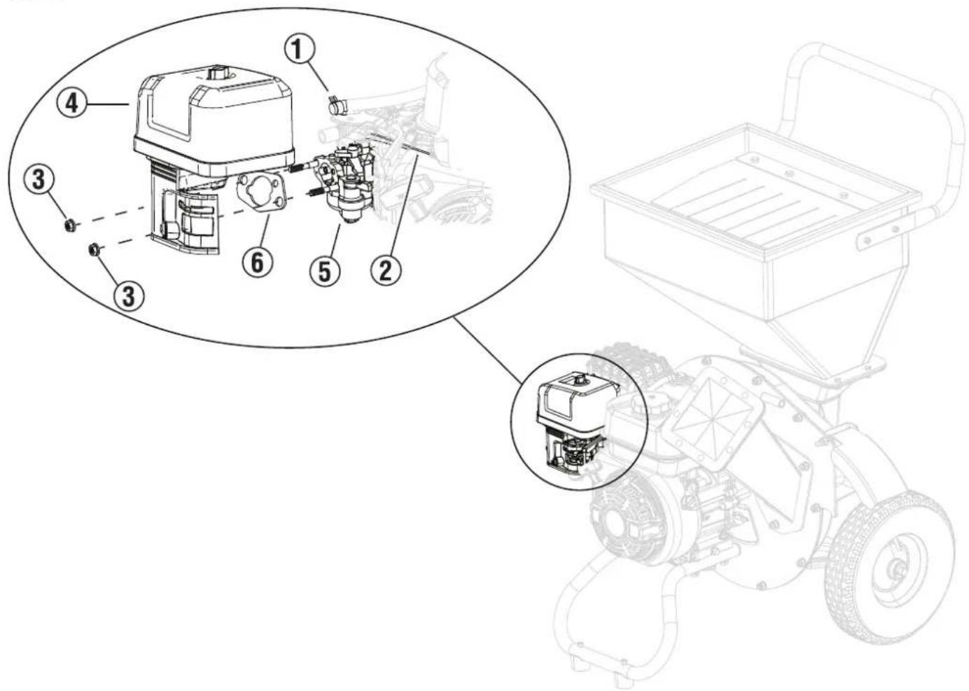
FIG. 20
- Turn off the unit.
- Close the fuel valve.
- Move the choke lever to the START position.
- Drain the fuel tank.
- See Figure 20. Remove the nuts (3) from the air filter assembly (4) and remove the air filter assembly from the bolts..
- Loosen the carburetor fuel line clamp (1).
- Remove the governor(2) and the speed control spring.
- Remove the carburetor (5) and air filter gasket (6).
To install the carburetor:
- See Figure 20. Attach the air filter gasket (6) and carburetor (5) to the unit. Be sure that the carburetor is aligned with the air filter gasket.
- Assemble the governor (2) and speed control spring to the carburetor throttle shaft.
- Attach the air filter assembly (4) to the unit and secure with the nuts (3).
- Tighten the carburetor fuel line clamp (1).
CHECKING/ADJUSTING THE VALVE CLEARANCE
NOTICE Checking and adjusting valve clearance must be done when the engine is cold.
- Turn the unit off and allow the engine to cool for 30 minutes.
- Place the unit on a level surface in a well-ventilated area.
- Remove the rocker arm cover and carefully remove the gasket. If the gasket is torn or damaged, it must be replaced.
- Remove the spark plug so the engine can be rotated more easily.
Pull the recoil handle to rotate the engine to top dead center (TDC). Looking through the spark plug hole; the piston should be at the top (both valves are closed).
See Figure 21. Both rocker arms should be loose at TDC on the compression stroke. If they are not, rotate the engine 360^
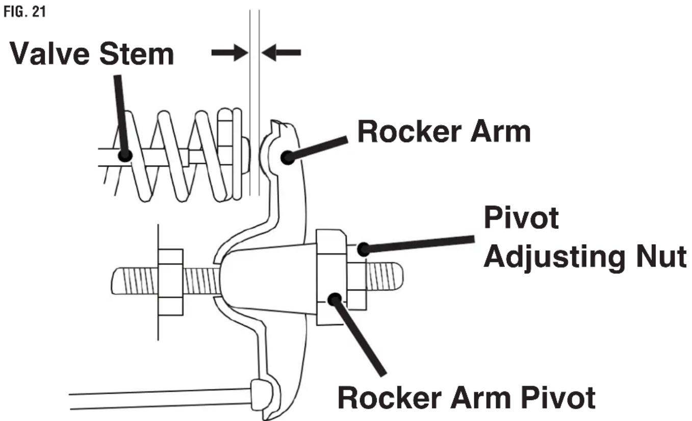
- Insert a feeler gauge between the rocker arm and the valve stem to measure valve clearance.
| Intake Valve Exhaust | ust Valve | |
| Valve Clearance | 0.0031 – 0.0047 in (0.08 – 0.12 mm) | 0.00512 – 0.00669 in (0.13 – 0.17 mm) |
| Torque | 8 – 12 Nm 8 – 12 | Nm |
- If an adjustment is necessary, loosen the jam nut.
- Slide the appropriate feeler gauge between the rocker arm and the valve stem.
- Tighten the adjustment bolt onto the push rod to obtain the specified clearance.
NOTE: You should be able to feel the rocker arm touch the feeler gauge.
- Hold the adjustment bolt in place and tighten the nut.
Torque: 106 inch-pound (12 Nm)
- Recheck valve clearance.
- If no further adjustments are needed, perform this procedure on the other valve.
- When finished, install the gasket, rocker arm cover, and spark plug.
INSPECTING THE SHREDDING HAMMER
- Turn off the motor and wait for the blades to stop completely. Be sure to disconnect the spark plug to prevent accidental starting.
WARNING Always wear gloves or cut-resistant hand protection when performing maintenance or servicing this tool. Failure to comply may result in serious personal injury.
- See Figure 22. Remove the bolts (3) from the access panel (2)
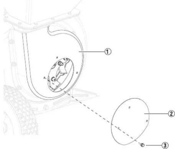
FIG. 22
- Remove the access panel from the rotor housing (1).
- See Figure 23. Inspect the rectangle hammers (1) and L-hammers (2) for wear and damage.
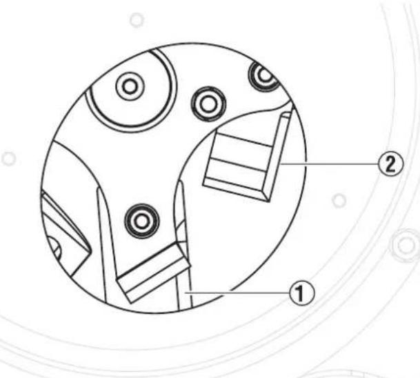
FIG. 23
- If the hammers are damaged or worn, contact a qualified technician for replacement of the hammers.
NOTE: Replacement hammers are not covered by warranty.
INSPECTING THE CHIPPING BLADES
- Turn off the motor and wait for the blades to stop completely. Be sure to disconnect the spark plug to prevent accidental starting.
- See Figure 24. Remove the nuts (1) from the chipper chute (2).
- Remove the chipper chute from the rotor housing.
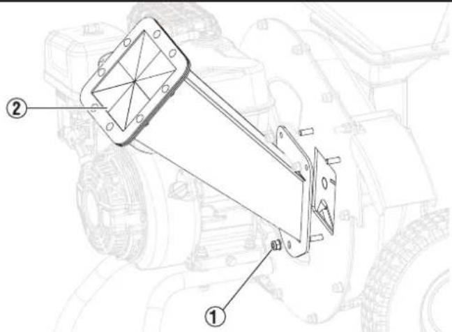
FIG. 24
- See Figure 25. Inspect the chipping blades (1) for damage and wear.
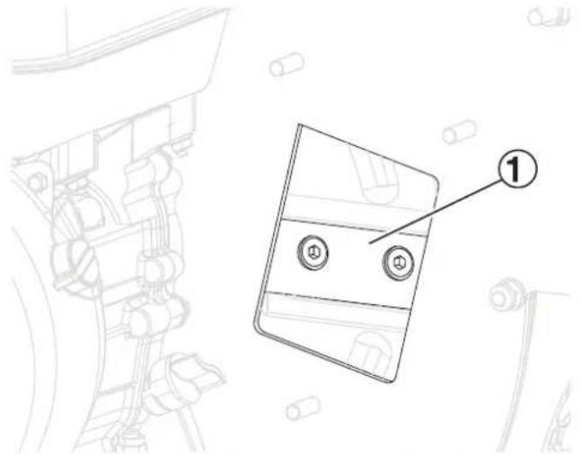
FIG. 25
- If the chipping blades are damaged or worn, contact a qualified technician for replacement of the hammers.
WARNING Blade sharpening must only be completed by a qualified professional. An imbalance of the blades could result in damage to the tool and serious injury to the operator.
| PROBLEM POSSIBLE CAUSE CORRECTION | ||
| The engine will not start | No fuel in the fuel tank or the fuel valve is closed Fill the fuel tank | with gasoline and open the fuel valve. |
| The choke is not in the START position, cold engine Move the choketo the START position. | ||
| Gasoline with more than 10% ethanol was used Flush gasoline from the fuel system and use recommended gasoline. | ||
| Low quality or deteriorated, old gasoline Drain the fuel tank and use fresh gasoline. | ||
| Carburetor was not primed Pull the recoil handle to prime the unit. | ||
| The fuel lines are clogged Use fuel additive to clean out the fuel lines. | ||
| The carburetor needle is stuck Gently tap the side of the carburetor float bowl with a screwdriver handle. | ||
| Too much fuel in the float bowl Move the choke to the RUN positon. Remove the spark plug and pull the recoil handle several times to air out the float bowl. Install the spark plug and set the choke to the START position. | ||
| The fuel filter is clogged Replace the fuel filter. | ||
| The spark plug boot is not connected securely Connect the spark | plug boot properly. | |
| The spark plug electrode is wet or dirty Clean the spark plug. | ||
| The spark plug gap is incorrect Correct the spark plug gap. | ||
| The spark plug boot is broken Replace the spark plug boot. | ||
| Incorrect spark timing or faulty ignition system Contact customer service. | ||
| Cylinder not lubricated | Pour a tablespoon of oil into the spark plug hole. Crank the engine multiple times and try starting the engine again. | |
| Loose or broken spark plug | Tighten the spark plug. If the issue persists, replace the spark plug. If the issue persists, inspect the head gasket. | |
| Loose cylinder head or damaged head gasket | Tighten the head. If the problem persists, replace the head gasket. | |
| Engine valves or tappets are mis-adjusted or stuck | Contact customer service. | |
| The oil level is low | Fill the engine oil level to the appropriate level. | |
| The unit is on an incline | Move the unit to a level surface. | |
| The engine misfires | The spark plug boot is loose | Inspect the spark plug boot and wire connections. |
| The spark plug gap is incorrect or the spark plug is damaged | Inspect the spark plug gap or replace the spark plug. | |
| The spark plug boot is defective | Replace the spark plug boot. | |
| Low quality or deteriorated, old gasoline Drain the fuel tank and use fresh gasoline. | ||
| The engine stops suddenly | The fuel tank is empty or is operating with improper gasoline Fill | the fuel tank with the appropriate gasoline. |
| Low oil shutdown Fill the engine oil to the appropriate level. | ||
| Defective fuel cap Test or replace the fuel cap. | ||
| Disconnected or improperly connected spark plug boot Secure the spark plug boot. | ||
| The engine stops when under a heavy load | The air filter is dirty Clean the air filter. | |
| The engine was operating cold Allow the engine time to warm up | before inserting items. | |
| The engine knocks | Low quality or deteriorated, old gasoline Drain the fuel tank and use fresh gasoline. | |
| The engine overloaded Do not exceed the load rating of the unit. | ||
| Incorrect spark timing, deposit buildup, worn engine, or other mechanical issue | Contact customer service. | |
| The engine backfires | Fuel quality is poor, stale, or old Drain the fuel tank and carburetor. Refill with fresh, unleaded gasoline (87-93 octane, up to 10% ethanol). | |
| The engine is not fully warmed up Allow the engine to run at no load for 3-5 minutes before chipping / shredding. | ||
| The valve clearance is out of specification or the intake valve is sticking | Contact customer service. | |
| The chipping is slow or the engine is stalling | The item diameter is too thick Do not insert items over 3 in diameter. | |
| The throttle is set too low Adjust the throttle to increase the engine speed. | ||
| Items vibrate or move excessively while chipping | The items are too hard or dried out The items are not appropriate for chipping. | |
| The chipping blades are dull or damaged Contact customer service. | ||
| The engine is on but material isn't being processed | The chipper / shredder is jammed Turn off the unit and wait for the blades to stop. Clear all debris from the main housing and the discharge port. | |
| The throttle is set too low Adjust the throttle to increase the engine speed. | ||
| There is an unusual noise or vibration during use | The rotor assembly is clogged | Stop adding material to the hopper / chipper chute. Allow the chipper / shredder to clear material before adding more. |
| The hammers are loose, damaged, or obstructed | Contact customer service. | |
Introduccion. 2-3
Seguridad 4-6
Componentes 7
Asamblea 8-11
12-16
Mantenimiento 17-24
SolutiOn de problemas 25-26
VOUS AVEZ DES QUESTIONS?
REEMPLACEMENT DU CARBURATEUR
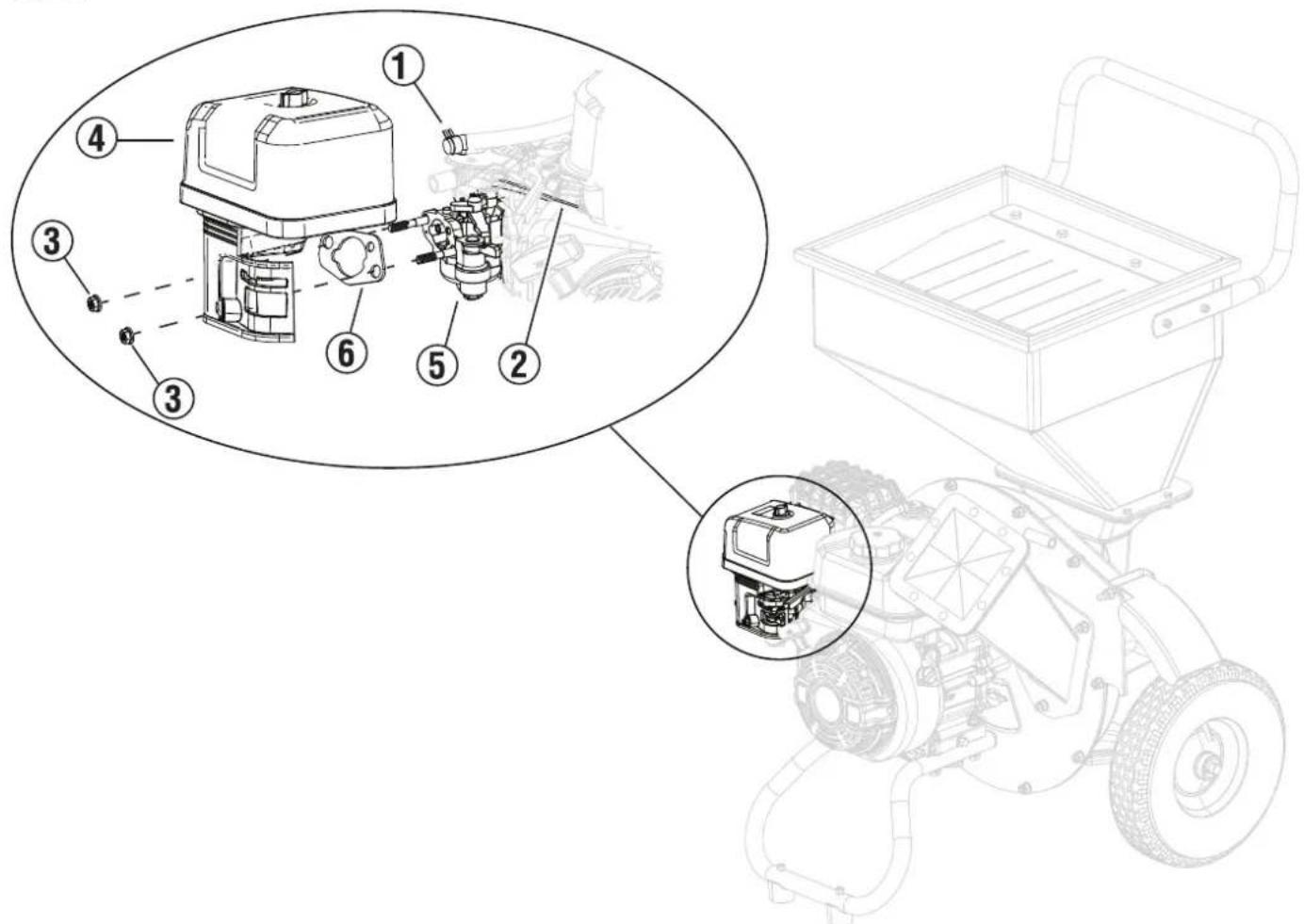
FIG. 20
www.westinghouse.com
Service Hotline (855) 944-3571
777 Manor Park Drive, Columbus, OH 43228
W and Westinghouse are trademarks of Westinghouse Electric Corporation.
Used under license by Westinghouse Outdoor Power Equipment.
© 2025 Westinghouse Outdoor Power Equipment, All Rights Reserved.
- INTRODUCTION
- WARNING
- DISCLAIMERS
- ALL RIGHTS RESERVED
- DANGER
- UPDATES
- PRODUCT REGISTRATION
- For Your Records
- SPECIFICATIONS
- HAVQEQUESTIONS?
- Email us at service@wpowereq.com
- or call 1-855-944-3571
- SAFETY DEFINITIONS
- CAUTION
- NOTICE
- SAFETY SYMBOLS
- READ AND UNDERSTAND ALL IN
- IMPORTANT SAFETY INSTRUCTIONS
- SAFETY PRECAUTIONS FOR GASOLINE AND GASOLINE VAPOR
- UNDERSTANDING THE TOOL
- REMOVING CARTON CONTENTS
- INSTALLING THE WHEELS
- INSTALLING THE SUPPORT STAND
- INSTALLING THE HOPPER
- INSTALLING THE DISCHARGE PORT COVER
- INSTALLING THE HANDLE
- INSTALLING THE CHIPPER CHUTE
- INSTALLING THE PRESS PLATE
- INSTALLING THE COLLECTION BAG
- KNOW HOW TO SAFELY LOCATE AND OPERATE THE UNIT
- ADDING OIL/CHECKING OIL LEVEL
- For initial oil fill:
- To check oil level:
- GASOLINE REQUIREMENTS
- Do not use E15 or E85 fuel in this product.
- USING FUEL STABILIZER
- ADDING GASOLINE
- BREAK-IN PERIOD
- STARTING THE ENGINE
- CHIPPING AND SHREDDING
- STOPPING THE ENGINE
- To stop the unit quickly in an emergency:
- CLEANING AND STORING THE UNIT
- MAINTENANCE SCHEDULE
- GENERAL MAINTENANCE
- CLEANING THE UNIT
- CLEANING/ REPLACING THE AIR FILTER
- CHANGING THE ENGINE OIL
- CLEANING/ REPLACING THE SPARK PLUG
- DRAINING THE FUEL TANK AND CARBURETOR FLOAT BOWL
- To drain the float bowl:
- To run the float bowl dry:
- To drain the fuel tank:
- REPLACING THE CARBURETOR
- To install the carburetor:
- CHECKING/ADJUSTING THE VALVE CLEARANCE
- Torque: 106 inch-pound (12 Nm)
- INSPECTING THE SHREDDING HAMMER
- INSPECTING THE CHIPPING BLADES
- REEMPLACEMENT DU CARBURATEUR
Brand : WESTINGHOUSE
Model : WChip3
Category : Garden shredder