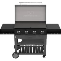
Performance 463814225 - Grill plate Char-Broil - Free user manual and instructions
Find the device manual for free Performance 463814225 Char-Broil in PDF.


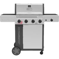
| Product Type | Propane Gas Grill Griddle |
| Brand | Char-Broil |
| Model | Performance 463814225 |
| Fuel | Propane (LPG) only - 20 lb (9.1 kg) max tank |
| Number of Burners | 4 main burners |
| Ignition | Electronic with AA battery (1.5 V) |
| Griddle Material | Steel with protective coating |
| Cooking Surface | Steel griddle plate |
| Seasoning | Required before first use (linseed oil, canola, etc.) |
| Safety | Overfill protection device, emergency shutoff, leak detection |
| Warranty | 2 years parts (excluding paint, surface corrosion) |
| Minimum Operating Temperature | 0°F (-18°C) |
| Safety Distance | 1 m from walls, 3 m from combustible materials, 7.5 m from flammable liquids |
| Cleaning | Scrape after use, water for stubborn residue, no soap |
| Grease Cup | Capacity 47 cl (16 oz) - drain after each cooking |
| Spare Parts | Burners, electrodes, regulator, hose, grease cup available |
| Repairability | Cleaning and replacement of burners possible by user |
| Certifications | ANSI Z223.1/NFPA 54, CSA B149.1, approved US/Canada |
Frequently Asked Questions - Performance 463814225 Char-Broil
User questions about Performance 463814225 Char-Broil
0 question about this device. Answer the ones you know or ask your own.
Ask a new question about this device
Download the instructions for your Grill plate in PDF format for free! Find your manual Performance 463814225 - Char-Broil and take your electronic device back in hand. On this page are published all the documents necessary for the use of your device. Performance 463814225 by Char-Broil.
USER MANUAL Performance 463814225 Char-Broil
natural_image
Line drawing of a portable electric grill with wheels and control panel (no text or symbols)FOR OUTDOOR USE ONLY
POUR USAGE EN MILIEU EXTÉRIEUR UNIQUEMENT ESTE JUEGO SÓLO SE PUEDE USAR EXTERIORS
TOOLS REQUIRED FOR ASSEMBLY:
- Adjustable wrench (not provided)
- Screwdriver (not provided)
- 7/16" Combination wrench (not provided)
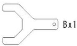
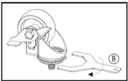
• Caster wrench (provided)
OUTILS REQUIS POUR L'ASSEMBLAGE:
Registration Card 59
INSTALLER/ASSEMBLER:
Leave this manual with consumer.

WARNING
- This instruction manual contains important information necessary for the proper assembly and safe use of the appliance.
- Read and follow all warnings and instructions before assembling and using the appliance.
- Follow all warnings and instructions when using the appliance.
- Keep this manual for future reference.

DANGER
- Never operate this appliance unattended.
- Never operate this appliance within 10ft (3m) of any structure, combustible material or other gas cylinder.
- Never operate this appliance within 25 ft (7.5 m) of any flammable liquid.
- If a fire should occur, keep away from the appliance and immediately call your fire department. Do not attempt to extinguish an oil or grease fire with water.
Failure to follow these instructions could result in fire, explosion or burn hazard, which could cause property damage, personal injury or death.
IMPORTANT SAFETY INFORMATION
SAFETY SYMBOLS
The symbols and boxes shown below explain what each heading means. Read and follow all of the messages found throughout the manual.

CAUTION
CAUTION: Indicates a potentially hazardous situation or unsafe practice which, if not avoided, may result in minor or moderate injury.

WARNING
WARNING: Indicates a potentially hazardous situation which, if not avoided, could result in death or serious injury.

DANGER
DANGER: Indicates an imminently hazardous situation which, if not avoided, will result in death or serious injury.

DANGER
If you smell gas:
- Shut off gas to the appliance
- Extinguish any open flame.
- Open lid.
- If odor continues, keep away from the appliance and immediately call your gas supplier or your fire department.
Failure to follow these instructions could result in fire, explosion or burn hazard, which could cause property damage, personal injury or death.

WARNING
- Do not store or use gasoline or other flammable liquids or vapors in the vicinity of this or any other appliance.
- An LP cylinder not connected for use shall not be stored in the vicinity of this or any other appliance.
- Minimum ambient operating temperature: 0°F (-18°C).
FOR YOUR SAFETY - INSTALLING YOUR GRILL

CAUTION
For residential use only. Do not use for commercial cooking.
Read and follow all safety statements, assembly instructions, and use and care directions before attempting to assemble and cook.
Some parts may contain sharp edges. Wear protective gloves if necessary.
Grease Fires
- Putting out grease fires by closing the lid is not possible. Grills are well ventilated for safety reasons.
- Do not use water on a grease fire. Personal injury may result. If a grease fire develops, turn knobs and LP tank off.
- If grill has not been regularly cleaned, a grease fire can occur that may damage the product. Pay close attention while preheating or burning off food residue to insure that a grease fire does not develop.
- The best way to prevent grease fires is regular cleaning of the grill following instructions on General Grill Cleaning and Cleaning The Burner Assembly.
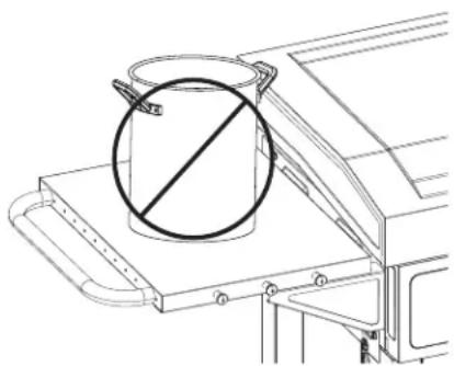
Using pots larger than 6 quarts in capacity could exceed weight limit of the side burner shelf or side shelf, resulting in failure of grill cart components.
natural_image
Technical line drawing of a mechanical assembly with a circular component and diagonal line marking (no text or symbols)
WARNING
- The use of alcohol, prescription or non-prescription drugs may impair the consumer's ability to properly assemble or safely operate the appliance.
- When cooking with oil or grease, have a type BC or ABC fire extinguisher readily available.
- In the event of an oil or grease fire do not attempt to extinguish with water. Immediately call the fire department. A type BC or ABC fire extinguisher may, in some circumstances contain the fire.
- In the event of rain, snow, hail, sleet, or other forms of precipitation while cooking with oil or grease, cover the cooking vessel immediately and turn off the appliance burners and gas supply. Do not attempt to move the appliance or cooking vessel.
- Do not move the appliance when in use. Allow the cooking vessel to cool to 115°F (45°C) before moving or storing.
- The cylinder should be disconnected when the appliance is not in use. Only cylinders marked "propane" shall be used.
Failure to follow all manufacturer's instructions could result in serious personal injury and/or property damage.
Do not attempt to repair or alter the hose/valve/regulator for any "assumed" defect. Any modification to this assembly will void your warranty and create the risk of a gas leak and fire. Use only authorized replacement parts supplied by manufacturer.
Do not cover grates with aluminum foil or any other material. This will block burner ventilation and create a potentially dangerous condition resulting in property damage and/or personal injury.
Top cover must be open when main burner(s) is in operation.
This product can expose you to chemicals including Lead, which is known to the State of California to cause cancer and birth defects or other reproductive harm. For more information go to www.P65Warnings.ca.gov.

If during operation the flames go out (You smell gas or cannot see the flame)
- Turn the burner controls OFF
- Open lid.
- Wait 5 minutes and repeat the lighting procedure.
If the burner goes out, gas will continue to flow out of the burner and could accidentally ignite with risk of injury.
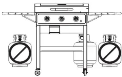
- NEVER store a spare LP cylinder under or near the appliance or in an enclosed area.
natural_image
Technical line drawing of a mechanical device with two circular pressure gauges (no text or symbols)- Never fill a cylinder beyond 80% full.
- An over filled or improperly stored cylinder is a hazard due to possible gas release from the safety relief valve. This could cause an intense fire with risk of property damage, serious injury or death.
- If you see, smell or hear gas escaping, immediately get away from the LP cylinder/appliance and call your fire department.
OUTDOOR
- An appliance is considered to be outdoors if installed with shelter no more inclusive than with walls on three sides, but with no overhead cover; all openings must be permanently open; sliding doors, garage doors, windows, or screened openings are not considered as permanent openings;
- An appliance is considered to be outdoors if installed with shelter no more inclusive than within a partial enclosure that includes an overhead cover and no more than two sidewalls. The sidewalls may be parallel, as in a breezeway, or at right angles to each other; all openings must be permanently open; sliding doors, garage doors, windows, or screened openings are not considered as permanent openings; or
- An appliance is considered to be outdoors if installed with shelter no more inclusive than within a partial enclosure that includes an overhead cover and three sidewalls, as long as 30% or more of the horizontal periphery of the enclosure is permanently open. All openings must be permanently open; sliding doors, garage doors, windows, or screened openings are not considered as permanent openings.
USE AND CARE
Installation Safety Precautions
- Use grill, as purchased, only with LP (propane) gas and the regulator/valve assembly supplied. If your grill is Dual Fuel ready, a conversion kit must be purchased for use with natural gas.
- Grill installation must conform with local codes, or in their absence of local codes, with either the National Fuel Gas Code, ANSI Z223.1/ NFPA 54, Natural Gas and Propane Installation Code, CSA B149.1, or Propane Storage and Handling Code, B149.2.
- All electrical accessories (such as rotisserie) must be electrically grounded in accordance with local codes, or National Electrical Code, ANSI / NFPA 70 or Canadian Electrical Code, CSA C22.1. Keep any electrical cords and/or fuel supply hoses away from any hot surfaces.
- This grill is safety certified for use in the United States and/or Canada only. Do not modify for use in any other location. Modification will result in a safety hazard.
LP Cylinder Removal, Transport and Storage
- Turn OFF all control knobs and LP cylinder valve. Turn coupling nut counterclockwise by hand only - do not use tools to disconnect. Loosen cylinder screw beneath bottom shelf or disconnect other retention means, then lift LP cylinder up and and out of cart. Install safety cap onto LP cylinder valve. Always use cap and strap supplied with valve. Failure to use safety cap as directed may result in serious personal injury and/or property damage.
- A disconnected LP cylinder in storage or being transported must have a safety cap installed (as shown). Do not store an LP cylinder in enclosed spaces such as a carport, garage, porch, covered patio or other building. Never leave an LP cylinder inside a vehicle which may become overheated by the sun.
- Do not store an LP cylinder in an area where children play.
LP Cylinder Valve

LP Cylinder
- The LP cylinder used with your grill must meet the following requirements:
- Use LP cylinders only with these required measurements: 12" (30.5cm) (diameter) x 18" (45.7 cm) (tall) with 20 lb. (9 kg.) capacity maximum.
- LP cylinders must be constructed and marked in accordance with specifications for LP cylinders of the U.S. Department of Transportation (DOT) or for Canada, CAN/CSA-B339, cylinders, spheres and tubes for transportation of dangerous goods, Transport Canada (TC). See LP cylinder collar for marking.
- LP cylinder valve must have:
- Type 1 outlet compatible with regulator or grill.
- Safety relief valve.
- UL listed Overfill Protection Device (OPD). This OPD safety feature is identified by a unique triangular hand wheel. Use only LP cylinders equipped with this type of valve.
- LP cylinder must be upright for vapor withdrawal and include collar to protect LP cylinder valve. Always keep LP cylinders in upright position during use, transit or storage.
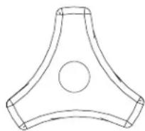
OPD Hand Wheel

natural_image
Line drawing of a gas cylinder with a valve and side mount (no text or symbols)LP cylinder in upright position for vapor withdrawal
LP (Liquefied Petroleum Gas)
- LP gas is nontoxic, odorless and colorless when produced. For Your Safety, LP gas has been given an odor (similar to rotten cabbage) so that it can be smelled.
- LP gas is highly flammable and may ignite unexpectedly when mixed with air.
LP Cylinder Filling
- Use only licensed and experienced dealers.
- LP dealer must purge new cylinder before filling.
- Dealer should NEVER fill LP cylinder more than 80% of LP cylinder volume. Volume of propane in cylinder will vary by temperature.
- A frosty regulator indicates gas overfill. Immediately close LP cylinder valve and call local LP gas dealer for assistance.
- Do not release liquid propane (LP) gas into the atmosphere. This is a hazardous practice.
- To remove gas from LP cylinder, contact an LP dealer or call a local fire department for assistance. Check the telephone directory under “Gas Companies” for nearest certified LP dealers.
USE AND CARE
LP Cylinder Exchange
- Many retailers that sell grills offer you the option of replacing your empty LP cylinder through an exchange service. Use only those reputable exchange companies that inspect, precision fill, test and certify their cylinders. Exchange your cylinder only for an OPD safety feature-equipped cylinder as described in the “LP Cylinder” section of this manual.
- Always keep new and exchanged LP cylinders in upright position during use, transit or storage.
- Leak test new and exchanged LP cylinders BEFORE connecting to grill.
- Place safety cap on cylinder valve outlet whenever the cylinder is not in use. Only install the type of safety cap on the cylinder valve outlet that is provided with the cylinder valve. Other types of caps or plugs may result in leakage of propane.
LP Cylinder Leak Test
For your safety
- Leak test must be repeated each time LP cylinder is exchanged or refilled.
- Do not smoke during leak test.
- Do not use an open flame to check for gas leaks.
- Grill must be leak tested outdoors in a well-ventilated area, away from ignition sources such as gas fired or electrical appliances. During leak test, keep grill away from open flames or sparks.
- Use a clean paintbrush and a 50/50 mild soap and water solution. Brush soapy solution onto areas indicated by arrows in figure below.
- Do not use household cleaning agents. Damage to gas train components can result.
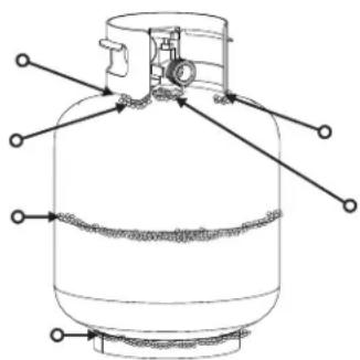
natural_image
Technical line drawing of a gas cylinder with internal components and directional arrows (no text or labels)
WARNING
If "growing" bubbles appear, do not use or move the LP cylinder. Contact an LP gas supplier or your fire department!

DANGER
- Do not insert any tool or foreign object into the valve outlet or safety relief valve. You may damage the valve and cause a leak. Leaking propane may result in explosion, fire, severe personal injury, or death.
Connecting Regulator to the LP Cylinder
- LP cylinder must be properly secured onto grill. (Refer to assembly section.)
- Turn all control knobs to the OFF position.
- Turn LP cylinder OFF by turning hand-wheel clockwise to a full stop.
- Remove the safety cap from LP cylinder valve. Always use cap and strap if supplied with valve.
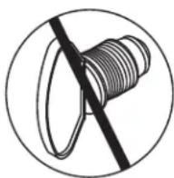
Do not use a POL transport plug (plastic part with external threads)! It will defeat the safety feature of the valve.
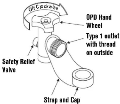
- Hold regulator and insert nipple into LP cylinder valve. Hand-tighten the coupling nut, holding regulator in a straight line with LP cylinder valve so as not to cross-thread the connection.
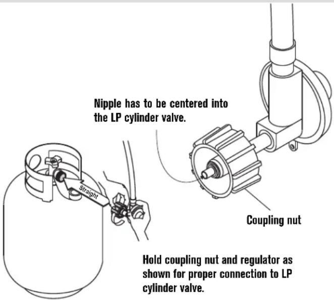
- Turn the coupling nut clockwise and tighten to a full stop. The regulator will seal on the back-check feature in the LP cylinder valve, resulting in some resistance. An additional one-half to three-quarters turn is required to complete the connection. Tighten by hand only – do not use tools.
NOTE:
If you cannot complete the connection, disconnect regulator and repeat steps 5 and 6. If you are still unable to complete the connection, do not use this regulator!
USE AND CARE

WARNING
- Do not use grill until leak-tested.
- If a leak is detected at any time, STOP! Turn off gas at source and correct leak.
- If you cannot stop a gas leak by closing the LP cylinder valve leave area and call your fire department!
- Outdoor gas appliance is not intended to be installed in or on a boat.
- Outdoor gas appliance is not intended to be installed in or on an RV.
- Never attempt to attach this grill to the self-contained LP gas system of a camper trailer or motor home.
- CHOKING HAZARD-Small parts. Not for children under 3 years.
Leak Testing Valves, Hose and Regulator
- Turn all grill control knobs to OFF.
- Be sure regulator is tightly connected to LP cylinder.
- Completely open LP cylinder valve by turning hand wheel counterclockwise. If you hear a rushing sound, turn gas off immediately. There is a major leak at the connection. Correct before proceeding.
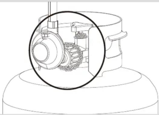
- Brush soapy solution onto areas circled below, or other similar fittings on your grill.
natural_image
Technical line drawing of a mechanical assembly with a magnified inset showing internal components (no text or symbols)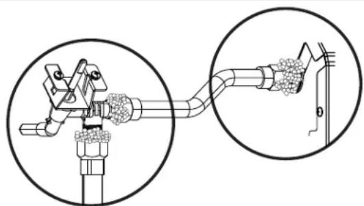
natural_image
Technical diagram of a mechanical device with two circular insets showing close-ups of components (no text or symbols)NOTE: Sideburner shelf fascia and other parts not shown for clarity.
NOTE: Your grill may NOT be equipped with a sideburner.
- If "growing" bubbles appear, there is a leak. Close LP cylinder valve immediately and retighten connections. If leaks cannot be stopped do not try to repair. Call for replacement parts.
- Always close LP cylinder valve after performing leak test by turning hand wheel clockwise.
Safety Tips
- Before opening LP cylinder valve, check the coupling nut for tightness.
- When grill is not in use, turn off all control knobs and LP cylinder valve.
- Never move grill while in operation or still hot.
- Some surfaces will be hot during use. Use long-handled barbecue utensils and oven mitts to avoid burns and splatters.
- Maximum load for sideburner and side shelf is 10 lbs.
- The grease tray or cup must be installed during use and emptied after each use. Do not remove grease tray or cup until grill has completely cooled.
- Clean grill often, preferably after each cookout. If a bristle brush is used to clean any of the grill cooking surfaces, ensure no loose bristles remain on cooking surfaces prior to grilling. It is not recommended to clean cooking surfaces while grill is hot.
- If you notice grease or other hot material dripping from grill onto valve, hose or regulator, turn off gas supply at once. Determine the cause, correct it, then clean and inspect valve, hose and regulator before continuing. Perform a leak test.
- Keep ventilation openings in cylinder enclosure (grill cart) free and clear of debris.
- Do not store objects or materials inside the grill cart enclosure that would block the flow of combustion air to the underside of either the control panel or the firebox bowl.
- The regulator may make a humming or whistling noise during operation. This will not affect safety or use of grill.
- If you have a grill problem see the "Troubleshooting" Section.
- If the regulator frosts, turn off grill and LP cylinder valve immediately. This indicates a problem with the cylinder and it should not be used on any product. Return to supplier!
Battery
a. Size of battery/ type/ designation: AA
b. Nominal Voltage: 1.5v
c. Number of battery required: 1PC
d. Battery included or not: Yes
Non-rechargeable batteries are not to be recharged.
Batteries are to be inserted with the correct polarity.
Exhausted batteries are to be removed from the product.
Do not dispose of the batteries in fire. Batteries may explode or leak.
Do not swallow the battery.
USE AND CARE

WARNING
LP GAS CYLINDER RUBBER SEAL INSPECTION.
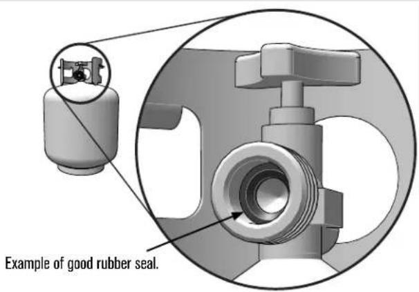
- Inspect the LP gas cylinder valve rubber seal for cracks, wear or deterioration prior to each use. A damaged rubber seal can cause a gas leak, possibly resulting in an explosion, fire, or severe bodily harm.
- It is recommended that you inspect the rubber seal each time the LP gas cylinder is connected to the appliance, each time it has been refilled, or if it has not been used for more than 60 days.
- DO NOT use a LP gas cylinder with a damaged rubber seal. The rubber seal CANNOT be repaired or replaced. Purchase a new cylinder or exchange the cylinder. You should inspect the seal before accepting a new or exchanged cylinder. DO NOT insert tools or foreign objects into the cylinder valve opening as this could damage the rubber seal.
- The leak check procedure outlined in the product guide/assembly manual MUST be followed each time the LP gas cylinder is connected to the appliance. Consult the product guide/assembly manual for the proper procedure and locations for leak checking.


WARNING
For Safe Use of Your Grill and to Avoid Serious Injury:
- Do not let children operate or play near grill.
- Keep grill area clear and free from materials that burn.
- Do not block holes in sides or back of grill.
- Check burner flames regularly.
- Use grill only in well-ventilated space. NEVER use in enclosed space such as carport, garage, porch, covered patio, or under an overhead structure of any kind.
- Do not use charcoal or ceramic briquets in a gas grill.
- Do not cover grates with aluminum foil or any other material. This will block burner ventilation and create a potentially dangerous condition resulting in property damage and/or personal injury.
- Use grill at least 3 ft. from any wall or surface. Maintain 10 ft. clearance to objects that can catch fire or sources of ignition such as pilot lights on water heaters, live electrical appliances, etc.
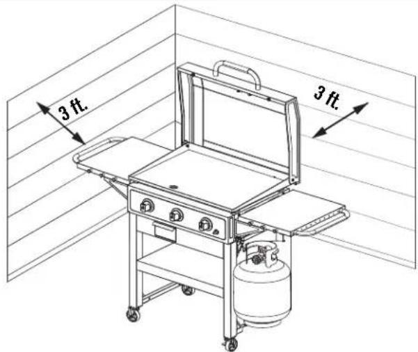
- NEVER attempt to light or re-light burner with lid closed. A buildup of non-ignited gas inside a closed grill is hazardous.
- Never operate grill with LP cylinder out of correct position specified in assembly instructions.
- Always close LP cylinder valve and remove coupling nut before moving LP cylinder from specified operation position.
- Apartment Dwellers:
Check with management to learn the requirements and fire codes for using an LP gas grill in your apartment complex. If allowed, use outside on the ground floor with a three (3) foot clearance from walls or rails. Do not use on or under balconies.
USE AND CARE
Ignitor Lighting
- Do not lean over grill while lighting.
- Turn gas burner control valves to ○ (off).
- Open lid during lighting or re-lighting.
- Turn ON gas at LP cylinder.
- To ignite, push and turn IGNITION BURNER knob to 🧑HIGH. Immediately, push and hold ELECTRONIC IGNITOR button until the burner lights.
- If ignition does NOT occur in 5 seconds, turn the burner controls off O, wait 5 minutes and repeat the lighting procedure.
- To ignite remaining burners, push and turn knob to the 🔊 HIGH position starting with the burners closest to the IGNITION BURNER first.

CAUTION
- Putting out grease fires by closing the lid is not possible. Grills are well ventilated for safety reasons.
- Do not use water on a grease fire. Personal injury may result. If a grease fire develops, turn knobs and LP cylinder off.
- Do not leave grill unattended while preheating or burning off food residue on HI. If grill has not been regularly cleaned, a grease fire can occur that may damage the product.

WARNING
Turn controls and gas source or tank OFF when not in use.

CAUTION
If ignition does NOT occur in 5 seconds, turn the burner controls ☐ off, wait 5 minutes and repeat the lighting procedure. If the burner does not ignite with the valve open, gas will continue to flow out of the burner and could accidentally ignite with risk of injury.
Match-Lighting
• Do not lean over grill while lighting.
1. Turn gas burner control valves to O (off).
2. Open lid during lighting or re-lighting.
3. Turn ON gas at LP cylinder.
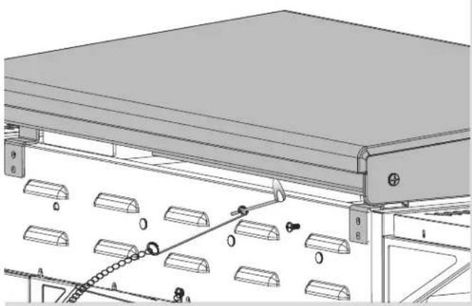
4. Place match into match holder (hanging from rear of firebox). Light match; then light burner by placing match through the gap under griddle. Immediately push in and turn burner knob to the 🔊 HIGH position. Be sure burner lights and stays lit.
5. Light adjacent burners in sequence by pushing knobs in and turning to the HIGH position.
natural_image
Technical line drawing of a mechanical assembly with rollers and a conveyor belt (no text or symbols)CB®
USE AND CARE
Burner Flame Check
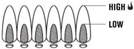
- Remove cooking grates and heat tents. Light burners, rotate knobs from HIGH to LOW. You should see a smaller flame in LOW position than seen on HIGH. Perform burner flame check on side burner, also. Always check flame prior to each use. If only low flame is seen refer to "Sudden drop or low flame" in the Troubleshooting Section.
Turning Grill Off
- Turn all knobs to the ○ off position. Turn LP cylinder off by turning hand-wheel clockwise to a full stop.
Ignitor Check
- Turn gas off at LP cylinder. Press and hold electronic ignitor button. "Click" should be heard and spark seen each time in each collector box or between burner and electrode. See "Troubleshooting" if no click or spark.
Valve Check
- Important: Make sure gas is off at LP cylinder before checking valves. Knobs lock in off position. To check valves, first push in knobs and release, knobs should spring back. If knobs do not spring back, replace valve assembly before using grill. Turn knobs to LOW position then turn back to off position. Valves should turn smoothly.
Hose Check
- Before each use, check to see if hoses are cut or worn or kinked. Replace damaged hoses before using grill. Use only valve/hose/regulator specified by manufacturer.
Storing Your Grill
- Clean cooking grates.
- Store in dry location.
- When LP cylinder is connected to grill, store outdoors in a well-ventilated space and out of reach of children.
- Cover grill if stored outdoors. Choose from a variety of grill covers offered by Char-Broil at charbroil.com.
- Store grill indoors ONLY if LP cylinder is turned off and disconnected, removed from grill and stored outdoors.
- When removing grill from storage, follow "Cleaning the Burner Assembly" instructions before starting grill.

CAUTION
SPIDER ALERT!
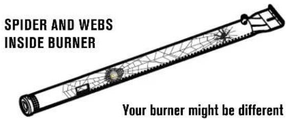
If your grill is getting hard to light or the flame is weak, check and clean the venturis and burners.
Spiders or small insects are known to create "flashback" problems by building nests and laying eggs in the grill's venturi or burner, obstructing the flow of gas. The backup gas can ignite behind the control panel. This flashback can damage your grill and cause injury. To prevent flashbacks and ensure good performance the burner and venturi tube assembly should be removed and cleaned when ever the grill has been idle for an extended period of time.
General Grill Cleaning
- Do not mistake brown or black accumulation of grease and smoke for paint. Interiors of gas grills are not painted at the factory (and should never be painted). Apply a strong solution of detergent and water or use a grill cleaner with scrub brush on insides of grill lid and bottom. Rinse and allow to completely air dry. Do not apply a caustic grill/oven cleaner to painted surfaces.
• Plastic parts: Wash with warm soapy water and wipe dry. - Do not use citrisol, abrasive cleaners, degreasers or a concentrated grill cleaner on plastic parts. Damage to and failure of parts can result.
- Porcelain surfaces: Because of glass-like composition, most residue can be wiped away with baking soda/water solution or specially formulated cleaner. Use nonabrasive scouring powder for stubborn stains.
- Painted surfaces: Wash with mild detergent or nonabrasive cleaner and warm soapy water. Wipe dry with a soft nonabrasive cloth.
- Stainless steel surfaces: To maintain your grill's high quality appearance, wash with mild detergent and warm soapy water and wipe dry with a soft cloth after each use. Baked-on grease deposits may require the use of an abrasive plastic cleaning pad. Use only in direction of brushed finish to avoid damage. Do not use abrasive pad on areas with graphics.
- Cooking surfaces: If a bristle brush is used to clean any of the grill cooking surfaces, ensure no loose bristles remain on cooking surfaces prior to grilling. It is NOT recommended to clean cooking surfaces while grill is hot.
USE AND CARE
Cleaning the Burner Assembly
Follow these instructions to clean and/or replace parts of burner assembly or if you have trouble igniting grill.
- Turn gas off at control knobs and LP cylinder.
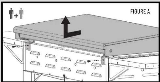
- Remove griddle (Figure A).
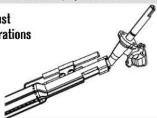
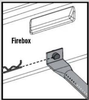
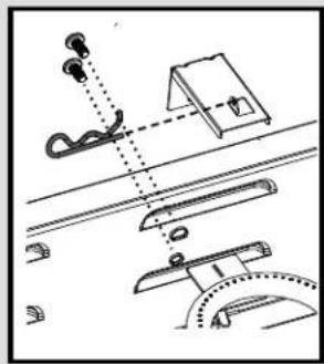
- Remove carryover tubes and hardware securing burners.
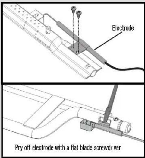
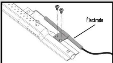
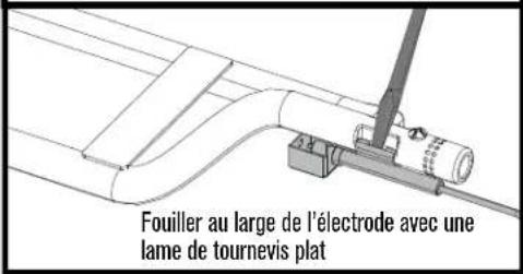
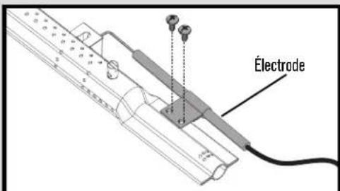
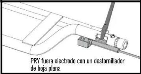
- Detach electrode from burner.
NOTE: Removal/Detachment method will depend on the burner configuration. See different configurations in illustrations below.
- Carefully lift each burner up and away from valve openings.
We suggest three ways to clean the burner tubes. Use the one easiest for you.
(A) Bend a stiff wire (a light weight coat hanger works well) into a small hook. Run the hook through each burner tube several times.

(B) Use a narrow bottle brush with a flexible handle (do not use a brass wire brush). Run the brush through each burner tube several times.
(C) Wear eye protection: Use an air hose to force air into the burner tube and out the burner ports. Check each port to make sure air comes out each hole.
-
Wire brush entire outer surface of burner to remove food residue and dirt.
-
Clean any blocked ports with a stiff wire such as an open paper clip.
-
Check burner for damage due to normal wear and corrosion, some holes may become enlarged. If any large cracks or holes are found, replace burner.
VERY IMPORTANT: Burner tubes must reengage valve openings. See illustrations at right.
Correct burner-to-valve engagement
natural_image
Technical line drawing of a mechanical device with lever and shaft (no text or symbols)- Attach electrode to burner.
- Carefully replace burners.
- Attach burners to brackets on firebox.
- Reposition carryover tubes and attach to burners.
- Replace griddle.
- Tighten the screws.
- Before cooking again on grill, perform a "Leak Test" and "Burner Flame Check".
natural_image
Diagram of a mechanical assembly with components and motion lines (no text or symbols)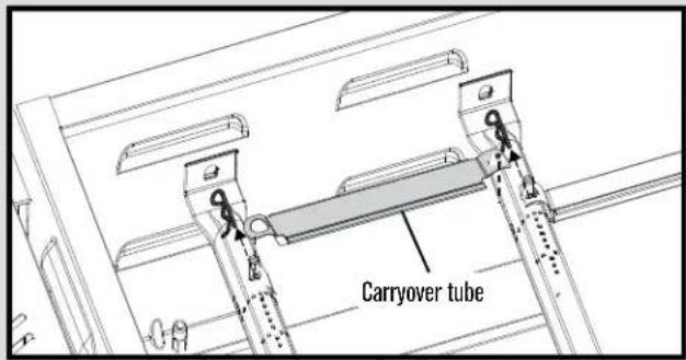
USE AND CARE
SEASONING
WHAT IS SEASONING?
Seasoning is a process by which oil is baked onto metal to create a stick resistant surface and protect against oxidization. Your Char-Broil®
Griddle comes with a thin layer of vegetable oil to protect against rust during shipping. This may leave some blemishes and discoloration on your griddle top. This is normal and will all even out during your seasoning process.
WHAT OIL SHOULD I USE?
Some oils are better than others for seasoning. Flax seed oil is a good oil for your initial seasoning since it creates a very durable bond. Flax oil has the highest level of Omega-3 fatty acids and has a very low smoke point. It is also a naturally hardening oil. This type of oil is good for your initial seasoning but it is more expensive than other options. Since it can also get brittle and flake over time, it is good for the initial seasoning but not for many cooking sessions. Just like cast iron, the more you cook on your Char-Broil® Griddle the better your seasoning layer will be. Any of the following oils can be used for your initial seasoning.
- Canola Oil (Rapeseed Oil)
- Coconut Oil
- Flax Seed Oil
- Olive Oil
- Vegetable Shortening (Crisco)
- Vegetable Oil
The idea behind your initial seasoning is to coat your griddle top with oil and heat the oil above its smoke point to polymerize the oil and create a bond with the griddle top. The result is a darkened, stick resistant surface.
- Apply small amount of oil (about 2-3 Tablespoons) to the surface of the griddle top and spread it around with a paper towel or a lint-free cloth.
- Turn all burners of your griddle on to medium-high heat.
- Heat the oil until it starts smoking and let it continue to heat on the griddle top until it stops smoking. Your griddle top will start to become darker in color. This is good.
- When the oil stops smoking (this should take approximately 25-30 minutes), turn your griddle off and let it cool down.
- Repeat steps 1 through 4 a few times until you have a nice dark surface on your griddle.
- After you have completed your initial seasoning, wipe down your griddle top with cooking oil for storing.
MAINTENANCE
There are some simple cleaning and seasoning steps for optimal performance of your Char-Broil® Griddle. We recommend covering your griddle after use if it will be left outside to protect it from the elements, especially in the winter months. The Char-Broil® Griddle Cover is available on Charbroil.com.
GRIDDLE SURFACE- CLEANING
FIRST TIME:
After assembling your griddle, you want to clean the griddle surface off with soap and hot water. Be sure you have the time to season your griddle before you start the cleaning process as they need to be completed at the same time. This will be the ONLY TIME you use soap and water to clean your griddle surface. Rinse and dry completely with paper towels. After this initial cleaning, proceed to the steps for Initial Griddle Seasoning.
AFTER EACH USE:
Clean the griddle surface after each use by scraping with a metal spatula or scraper and wiping down the griddle surface with a cloth or paper towel. For tough food residue, pour water onto the hot griddle surface and let the residue boil off. DO NOT USE SOAP to clean the griddle surface, as that will break down the seasoning you have created on the surface. Treat your griddle top much like you would cast iron skillets and Dutch ovens. Store your griddle in a cool, dry place, preferably with a cover.
GREASE CUP
The Grease Cup has a capacity of 16 ounces (2 cups) and should be emptied after each cook session. Depending on the foods you are cooking, this grease cup can fill up quickly. Care should be taken when emptying the cup, it is preferred to empty the grease once it is cooled down, as both the grease cup and the grease will be very hot during and immediately following your cook session. If you find that the grease cup is getting full mid-cooking, you should use a heat proof glove to carefully remove and empty the cup. The grease cup can be washed with warm, soapy water but should not go into the dishwasher.
LIMITED WARRANTY
This warranty only applies to units purchased from an authorized retailer. Manufacturer warrants to the original consumer-purchaser only that this product shall be free from defects in workmanship and materials after correct assembly and under normal and reasonable home use for the periods indicated below beginning on the date of purchase*. The manufacturer reserves the right to require that defective parts be returned, postage and or freight pre-paid by the consumer for review and examination.
SCOPE OF COVERAGE PERIOD OF COVERAGE TYPE OF FAILURE COVERAGE
| All Parts 2 year from date of purchase* PERFORATION, | MANUFACTURING, AND MATERIAL | DEFECTS ONLY |
*Note: A dated sales receipt WILL be required for warranty service.
The original consumer-purchaser will be responsible for all shipping charges for parts replaced under the terms of this limited warranty.
This limited warranty is applicable in the United States and Canada only, is only available to the original owner of the product and is not transferable. Manufacturer requires proof of your date of purchase. Therefore, you should retain your sales slip or invoice. Registering your product is not a substitute for proof of purchase and the manufacturer is not responsible for or required to retain proof of purchase records.
This limited warranty applies to the functionality of the product ONLY and does not cover cosmetic issues such as scratches, dents, corrosions or discoloring by heat, abrasive and chemical cleaners or any tools used in the assembly or installation of the appliance, surface rust, or the discoloration of stainless steel surfaces. Paint is not warranted and will require touch up. RUST is not considered a manufacturing or materials defect.
This limited warranty will not reimburse you for the cost of any inconvenience, food, personal injury or property damage.
ITEMS MANUFACTURER WILL NOT PAY FOR:
- Shipping cost, standard or expedited, for warranty and replacement parts.
- Service calls to your home.
- Repairs when your product is used for other than normal, single-family household or residential use.
- Damage, failures, or operating difficulties resulting from accident, alteration, careless handling, misuse, abuse, fire, flood, acts of God, improper installation or maintenance, installation not in accordance with electrical or plumbing codes, or use of products not approved by the manufacturer.
- Any food loss due to product failures or operating difficulties.
- Replacement parts or repair labor costs for units operated outside the United States or Canada.
- Pickup and delivery of your product.
- Repairs to parts or systems resulting from unauthorized modifications made to the product.
- The removal and/or reinstallation of your product.
DISCLAIMER OF IMPLIED WARRANTIES and LIMITATION OF REMEDIES
Repair or replacement of defective parts is your exclusive remedy under the terms of this limited warranty. In the event of parts availability issues, the manufacturer reserves the right to substitute like or similar parts that are equally functional.
Manufacturer will not be responsible for any consequential or incidental damages arising from the breach of either this limited warranty or any applicable implied warranty, or for failure or damage resulting from acts of God, improper care and maintenance, grease fire, accident, alteration, replacement of parts by anyone other than Manufacturer, misuse, transportation, commercial use, abuse, hostile environments (inclement weather, acts of nature, animal tampering), improper installation or installation not in accordance with local codes or printed manufacturer instructions.
THIS LIMITED WARRANTY IS THE SOLE EXPRESS WARRANTY GIVEN BY THE MANUFACTURER. NO PRODUCT PERFORMANCE SPECIFICATION OR DESCRIPTION WHEREVER APPEARING IS WARRANTED BY MANUFACTURER EXCEPT TO THE EXTENT SET FORTH IN THIS LIMITED WARRANTY. ANY IMPLIED WARRANTY PROTECTION ARISING UNDER THE LAWS OF ANY STATE, INCLUDING IMPLIED WARRANTY OF MERCHANTABILITY OR FITNESS FOR A PARTICULAR PURPOSE OR USE, IS HEREBY LIMITED IN DURATION TO THE DURATION OF THIS LIMITED WARRANTY.
Neither dealers nor the retail establishment selling this product has any authority to make any additional warranties or to promise remedies in addition to or inconsistent with those stated above. Manufacturer's maximum liability, in any event, shall not exceed the purchase price of the product paid by the original consumer.
NOTE: Some states do not allow an exclusion or limitation of incidental or consequential damages, so some of the above limitations or exclusions may not apply to you. This limited warranty gives you specific legal rights as set forth herein. You may also have other rights which vary from state to state. In the state of California only, if refinishing or replacement of the product is not commercially practicable, the retailer selling this product or the Manufacturer will refund the purchase price paid for the product, less the amount directly attributable to use by the original consumer-purchaser prior to discovery of the nonconformity. In addition, in the state of California only, you may take the product to the retail establishment selling this product in order to obtain performance under this limited warranty.
If you wish to obtain performance of any obligation under this limited warranty, you should
write to:
Consumer Relations
P. O. Box 1240
Columbus, GA 31904-1240
Consumer returns will not be accepted unless a valid Return Authorization is first acquired. Authorized returns are clearly marked on the outside of the package with an RA number and the package is shipped freight/postage pre-paid. Consumer returns that do not meet these standards will be refused.
TABLE DES MATIÈRES
natural_image
Technical line drawing of a mechanical assembly with a cylindrical component and lever (no text or symbols)
AVERTISSEMENT
If during operation the flames go out (You smell gas or cannot see the flame)
natural_image
Technical line drawing of a mechanical device with two circular pressure gauges and control knobs (no text or symbols)natural_image
Line drawing of a cylindrical gas cylinder with a side-mounted valve (no text or symbols)natural_image
Line drawing of a gas cylinder with internal components and directional arrows indicating flow or movement (no text or symbols)
AVERTISSEMENT
natural_image
Technical line drawing of a mechanical assembly with a magnified circular detail (no text or symbols)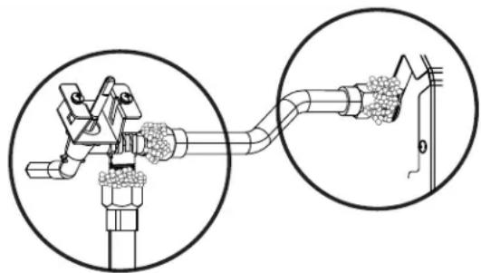
natural_image
Diagram of a mechanical device with two circular insets showing a close-up view of a granular material being inserted into a pipe (no text or symbols present)natural_image
Technical line drawing of a mechanical assembly with no visible text or symbols
ATTENTION
natural_image
Technical line drawing of a mechanical assembly with no visible text or symbolsnatural_image
Diagram showing mechanical components and connections without any text or symbols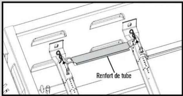
natural_image
Technical line drawing of a mechanical assembly with a circular component and mounting bracket (no text or symbols)GRO ADVERTENCIA
natural_image
Technical line drawing of a mechanical device with two cylindrical tanks and control knobs (no text or symbols)natural_image
Line drawing of a gas cylinder with attached valve (no text or symbols)natural_image
Line drawing of a cylindrical gas cylinder with attached mechanical components and directional arrows indicating flow or movement (no text or symbols)
ADVERTENCIA
natural_image
Technical line drawing of a mechanical assembly with a magnified circular detail (no text or symbols)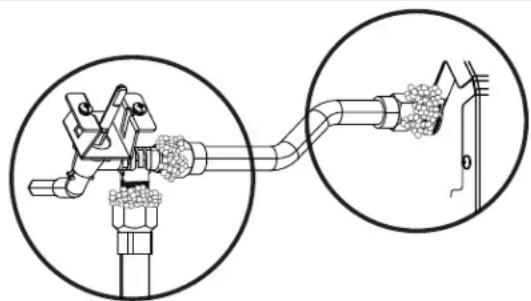
natural_image
Diagram of a mechanical device with a close-up inset showing internal components (no text or symbols)natural_image
Technical diagram of a mechanical assembly with rollers and pulleys (no text or symbols)
ADVERTENCIA
natural_image
Diagram of a mechanical assembly with components and motion lines, no visible text or symbols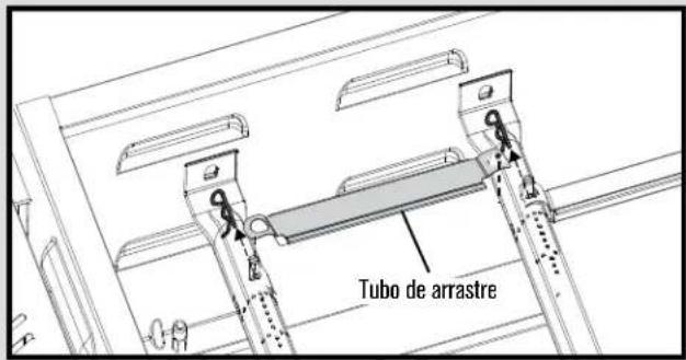
PARTS LIST
| Key Qty Description |
| 1 1 BOTTOM SHELF FRAME |
| 2 9 SLATS, F/ BOTTOM SHELF |
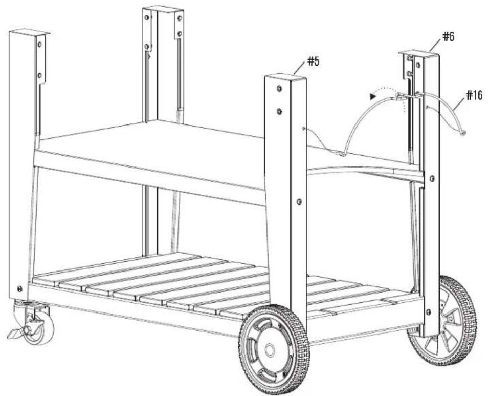
| 3 1 LEFT FRONT LEG (C) |
| 4 1 LEFT REAR LEG (A) |
| 5 1 RIGHT FRONT LEG (D) |
| 6 1 RIGHT REAR LEG (B) |
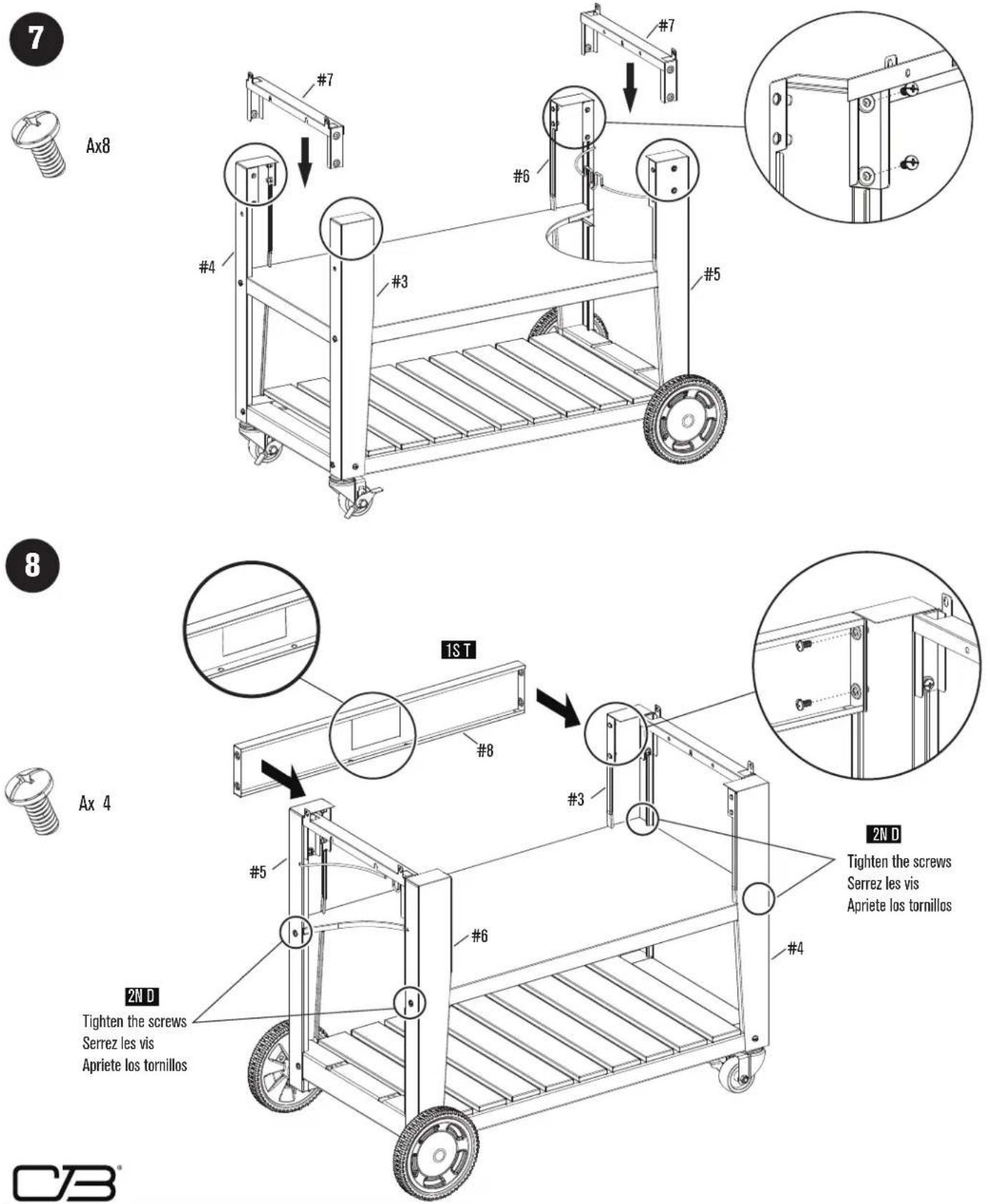
| 7 2 LEG UPPER SUPPORT |
| 8 1 UPPER FRONT CART PANEL |
| 9 1 REAR LEFT SUPPORT PLATE |
| 10 1 REAR RIGHT SUPPORT PLATE |
| 11 1 MIDDLE CART SHELF |
| 12 2 CASTER, W/ LOCK |
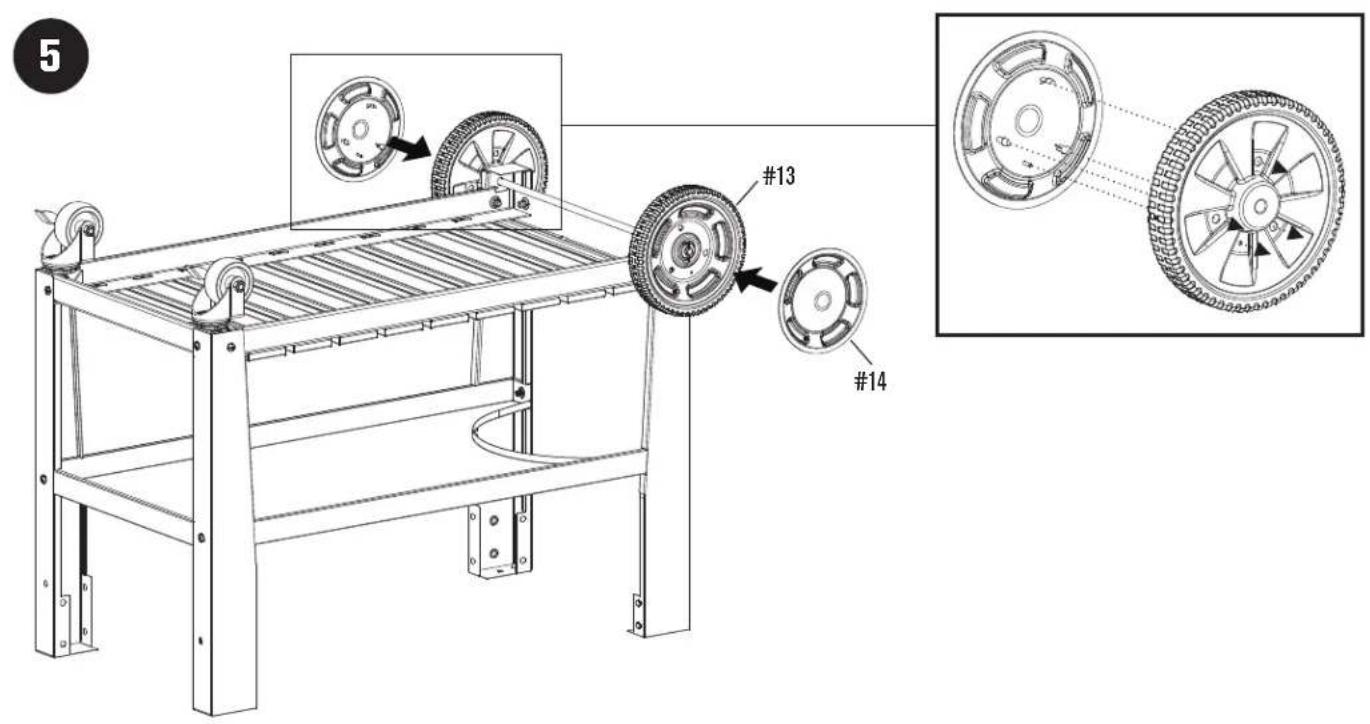
| 13 2 WHEEL |
| 14 2 WHEEL HUB CAP |
| 15 1 KIT, AXLE F/ WHEEL |
| 16 1 TANK WIRE |
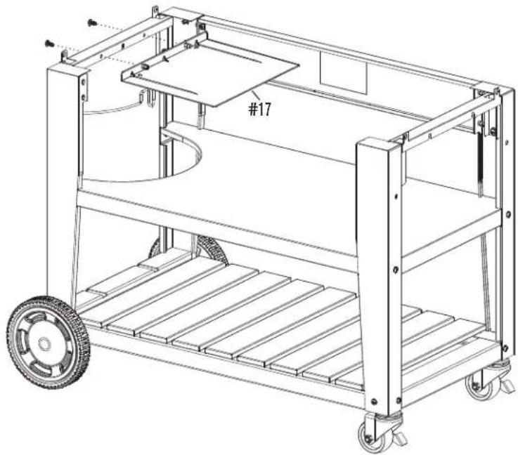
| 17 1 TANK HEAT SHIELD |
| 18 1 BOTTLE OPENER |
| 19 1 FIREBOX |
| 20 1 FIREBOX SEPARATOR |
| 21 4 BURNER TUBE |
| 22 1 ELECTRODE, 600MM WIRE |
| 23 1 ELECTRODE, 400MM WIRE |
| 24 1 ELECTRODE, 200MM WIRE |
| 25 1 ELECTRODE, 800MM WIRE |
| 26 2 CARRYOVER TUBE |
| 27 1 CONTROL PANEL |
| 28 1 FRONT TOWEL BAR |
| 29 1 HOSE VALVE REGULATOR ASSEMBLY |
| 30 4 BEZEL, F/ CONTROL KNOB |
| 31 4 CONTROL KNOB |
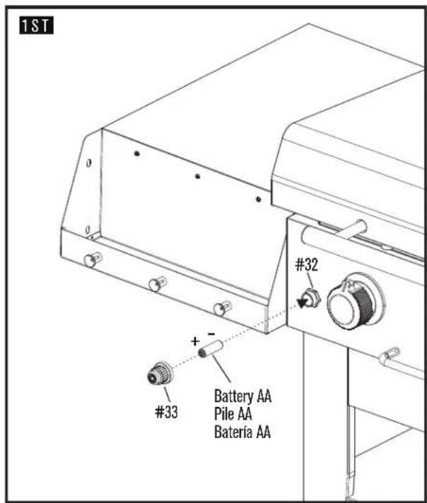
| 32 1 ELECTRONIC IGNITION MODULE |
| 33 1 BUTTON F/ EI MODULE |
| 34 1 HEAT SHIELD, F/ EI MODULE |
| 35 1 GREASE DUCT |
| Key Qty Description | |
| 36 1 LEFT GREASE TRAY BRACKET | |
| 37 1 RIGHT GREASE TRAY BRACKET | |
| 38 1 GREASE TRAY | |
| 39 1 GRIDDLE | |
| 40 2 SIDE SHELF | |
| 41 2 SHELF BRACKET, LEFT FRONT, RIGHT REAR | |
| 42 2 SHELF BRACKET, LEFT REAR, RIGHT FRONT | |
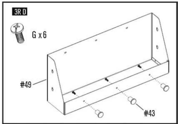
| 43 6 TOOL HOOK | |
| 44 1 MATCH HOLDER | |
| 45 1 HDSE/ REGULATOR REPLACEMENT ONLY | |
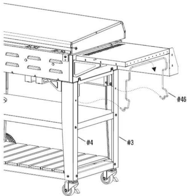
| 46 1 TRASH BAG HOLDER | |
| 47 4 BURNER BRACE | |
| 48 2 RUBBER BUMPER, F/ TOP LID, REAR | |
| 49 2 FASCIA, F/ SIDE SHELF | |
| 50 1 TOP LID | |
| 51 1 LOGO PLATE | |
| 52 1 HANDLE, F/ TOP LID | |
| 53 2 RUBBER BUMPER, F/ TOP LID | |
| 54 1 TOP LID HARDWARE | |
NOT Pictured
| ... 1 PRODUCT GUIDE |
| ... 1 HARDWARE PACK |
| ... 1 CASTER WRENCH |
NOTE: Some grill parts shown in the assembly steps may differ slightly in appearance from those on your particular grill model. However, the method of assembly remains the same.
LISTE DES PIÈCES
| Réf. Qté Description | |
| 1 1 CHÂSSIS DE LA TABLETTE INFÉRIEURE | |
| 2 9 LATTES, POUR TABLETTE INFÉRIEURE | |
| 3 1 PIED AVANT GAUCHE (C) | |
| 4 1 PIED ARRIÈRE GAUCHE (A) | |
| 5 1 PIED AVANT DROIT (D) | |
| 6 1 PIED ARRIÈRE DROIT (B) | |
| 7 2 SUPPORT DE PIED SUPÉRIEUR | |
| 8 1 PANNEAU AVANT SUPÉRIEUR DU CHARIOT | |
| 9 1 PLAQUE DE SUPPORT ARRIÈRE GAUCHE | |
| 10 1 PLAQUE DE SUPPORT ARRIÈRE DROITE | |
| 11 1 TABLETTE CENTRALE DU CHARIOT | |
| 12 2 ROULETTE, A BLOCAGE | |
| 13 2 ROUE | |
| 14 2 ENJOLIVEUR DE ROUE | |
| 15 1 TROUSSE, ESSIEUR POUR ROUE | |
| 16 1 FIL POUR BOUTEILLE | |
| 17 1 ÉCRAN THERMIQUE POUR BOUTEILLE | |
| 18 1 OUVRE-BOUTEILLE | |
| 19 1 FOYER | |
| 20 1 SÉPARATEUR DE FOYER | |
| 21 4 TUBE DE BRÛLEUR | |
| 22 1 ÉLECTRODE, FIL DE 600 MM | |
| 23 1 ÉLECTRODE, FIL DE 400 MM | |
| 24 1 ÉLECTRODE, FIL DE 200 MM | |
| 25 1 ÉLECTRODE, FIL DE 800 MM | |
| 26 2 TUBE DE RÉPARTITION | |
| 27 1 PANNEAU DE COMMANDE | |
| 28 1 BARRE À SERVIETTES AVANT | |
| 29 1 ASSEMBLAGE DE TUYAU/ROBINET/RÉGULATEUR | |
| 30 4 ENJOLIVEUR POUR BOUTON DE RÉGLAGE | |
| 31 4 BOUTON DE RÉGLAGE | |
| 32 1 MODULE D'ALLUMAGE ÉLECTRONIQUE | |
| 33 1 BOUTON, POUR MODULE D'ALLUMAGE ÉLECTRONIQUE | |
| 34 | 1 ÉCRAN THERMIQUE, POUR MODULE D'ALLUMAGE ÉLEC-TRONIQUE |
| 35 1 CONDUITE DE GRAISSE | |
| Réf. Qté Description | ||
| 36 1 SUPPORT DE GAUCHE DU BAC À GRAISSE | ||
| 37 1 SUPPORT DE DROITE DU BAC À GRAISSE | ||
| 38 1 BAC À GRAISSE | ||
| 39 1 PLAQUE DE CUISSON | ||
| 40 2 TABLETTE LATÉRALE | ||
| 41 2 TABLETTE LATÉRALE, AVANT GAUCHE, ARRIÈRE DROITE | ||
| 42 2 TABLETTE LATÉRALE, ARRIÈRE GAUCHE, AVANT DROITE | ||
| 43 6 CROCHET À JUSTENSILES | ||
| 44 1 PORTE-ALLUMETTES | ||
| 45 1 REMPLACEMENT DU TUYAU/RÉGULATEUR SEULEMENT | ||
| 46 1 SUPPORT DE SAC À DÉCHETS | ||
| 47 4 SUPPORT DU BRÛLEUR | ||
| 48 | 2 | BUTOIR EN CAOUTCHOUC, POUR COUVERCLE SUPÉRIEUR, ARRIÈRE |
| 49 2 BORDURE POUR TABLETTE LATÉRALE | ||
| 50 1 COUVERCLE SUPÉRIEUR | ||
| 51 1 PLAQUE DE LOGO | ||
| 52 1 POIGNÉE POUR COUVERCLE SUPÉRIEUR | ||
| 53 2 BUTOIR EN CAOUTCHOUC, POUR COUVERCLE SUPÉRIEUR | ||
| 54 1 MATÉRIEL DU COUVERCLE SUPÉRIEUR | ||
NON illustré
| ... 1 MANUEL D'ASSEMBLAGE |
| ... 1 SAC DE FERRURES |
| ... 1 CLÉ À ROULETTES |
4
C×3
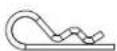
D x 1
natural_image
Technical line drawing of a mechanical clamp or lever assembly (no text or symbols)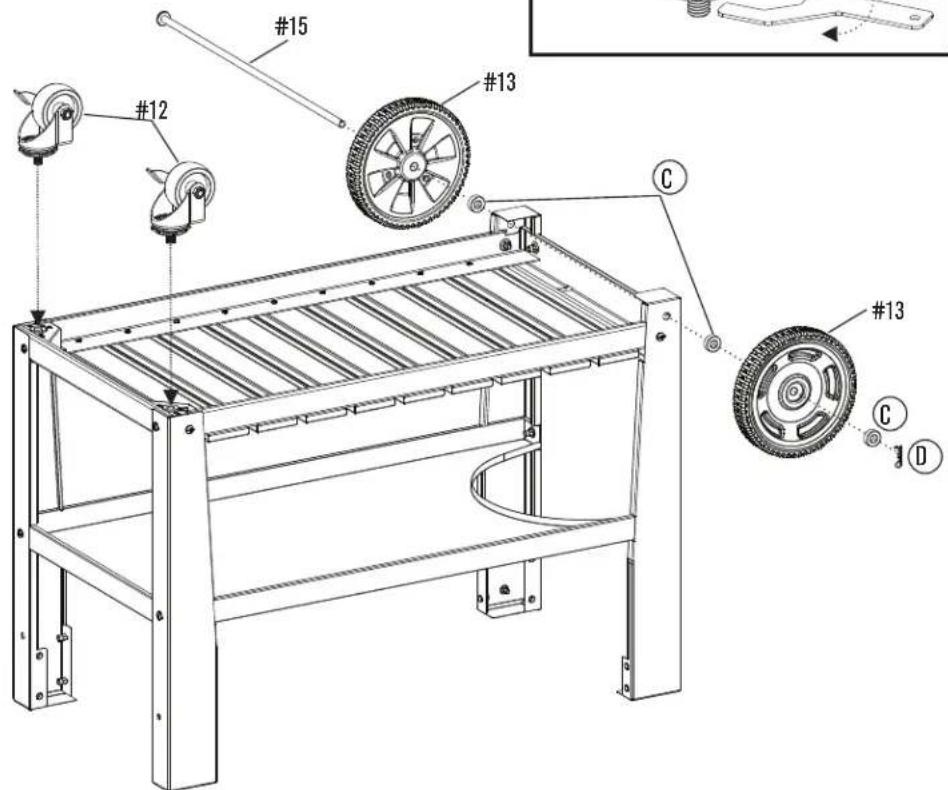
CB ^
ASSEMBLY / ASSEMBLAGE / ASAMBLEA
6
CB ^
ASSEMBLY / ASSEMBLAGE / ASAMBLEA
ASSEMBLY / ASSEMBLAGE / ASAMBLEA
9
Ax 2
natural_image
Technical line drawing of a two-tiered mechanical cart with wheels and a handle, no text or symbols present10
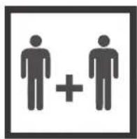
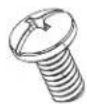
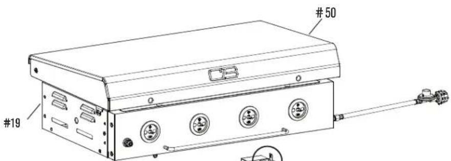
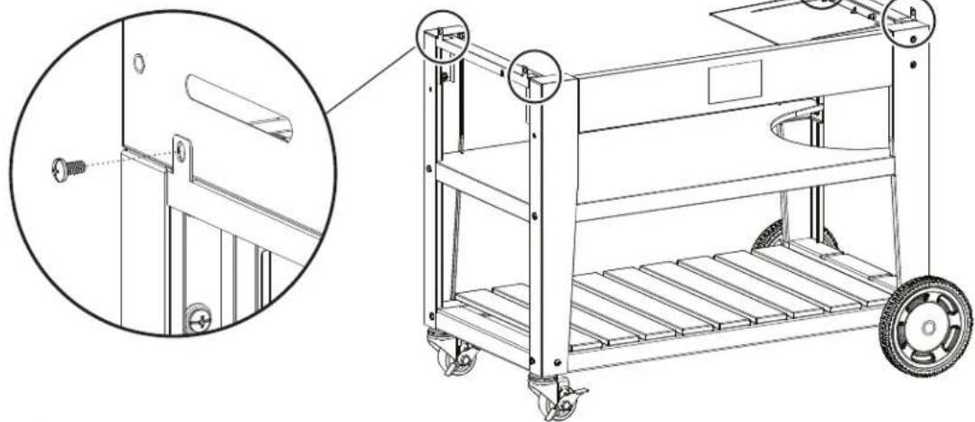
Ax 4
natural_image
Technical line drawing of a wheeled cart with a close-up inset showing a screw inserted into a rail (no text or symbols present)CB ^®
ASSEMBLY / ASSEMBLAGE / ASAMBLEA
11
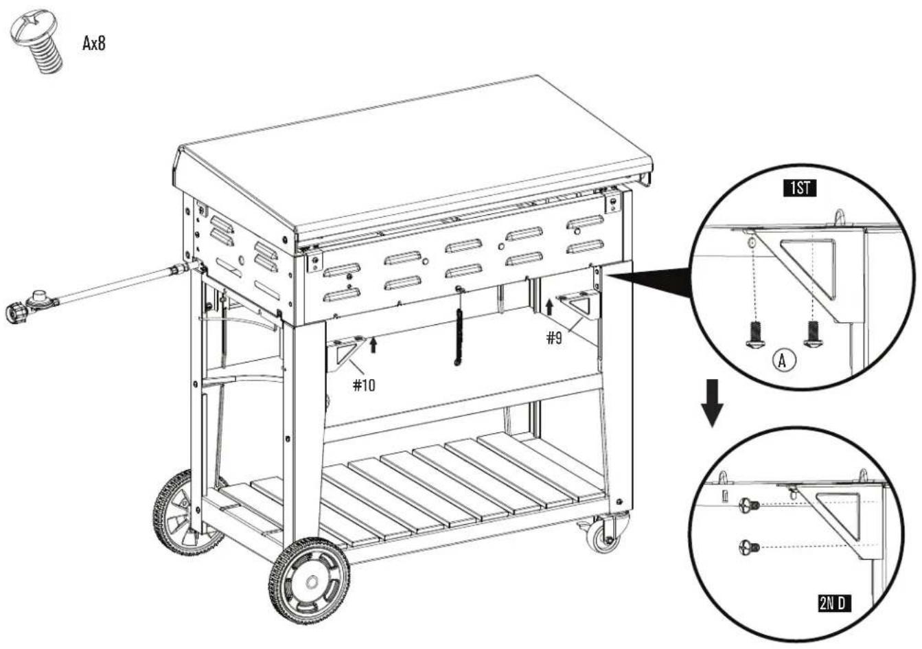
ASSEMBLY / ASSEMBLAGE / ASAMBLEA
12
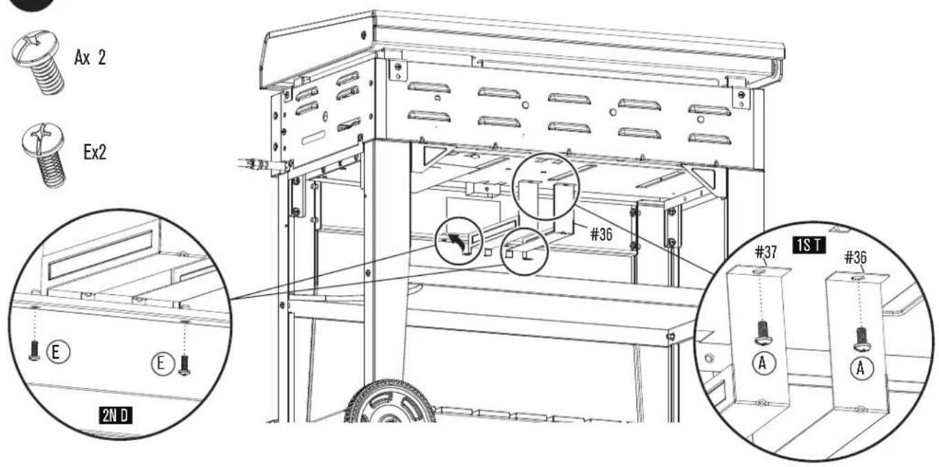
13
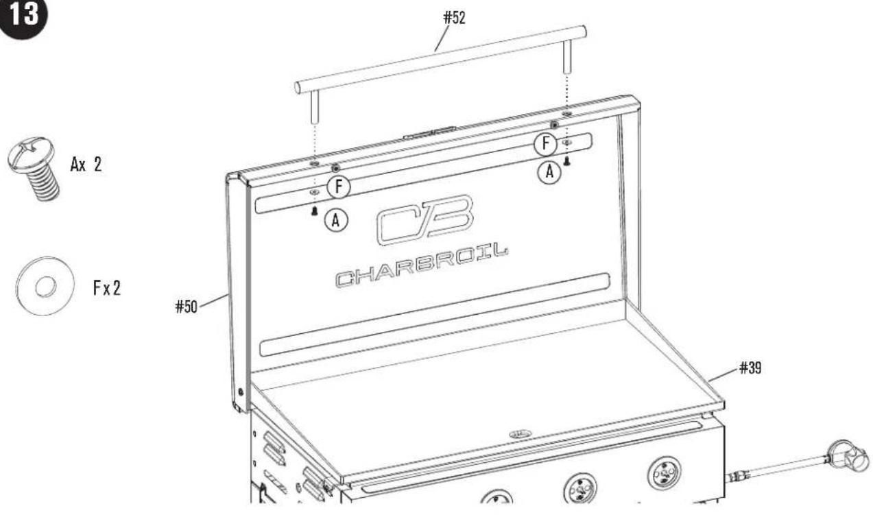
ASSEMBLY / ASSEMBLAGE / ASAMBLEA
14
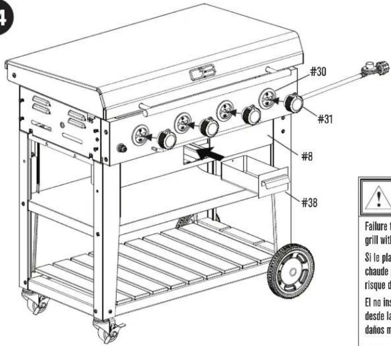

CAUTION/ ATTENTION/ ADVERTENCIA

Failure to install grease tray will cause hot grease to drip from bottom of grill with risk of fire or property damage.
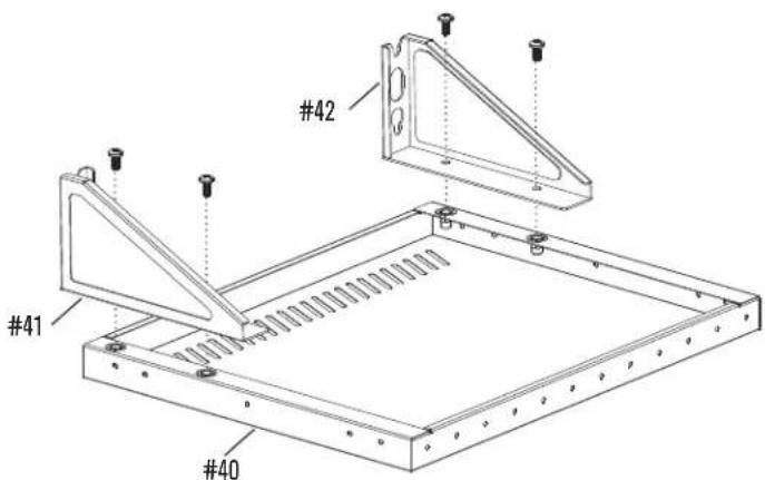
CB ^
ASSEMBLY / ASSEMBLAGE / ASAMBLEA
16
X2
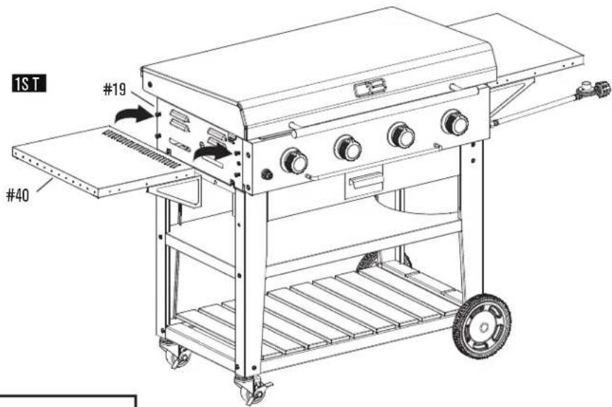
2ND
natural_image
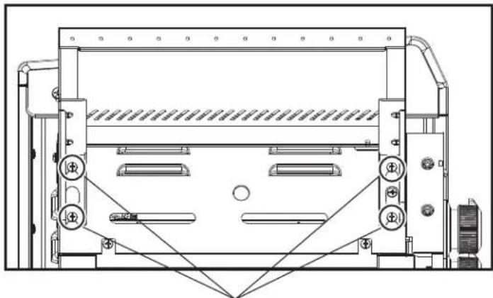
Technical line drawing of a mechanical device with internal components and mounting brackets (no text or symbols)Tighten the screws
Serrez les vis
Apriete los tornillos
Ax 4

H×6
In case screws A are unable to align with the holes, adjust the assembly by loosening the screws tightened in picture 2ND. After screws A are secured, tighten the screws.
ASSEMBLY / ASSEMBLAGE / ASAMBLEA
17
18
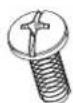
Ex2
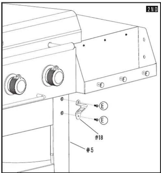
CB®
ASSEMBLY / ASSEMBLAGE / ASAMBLEA
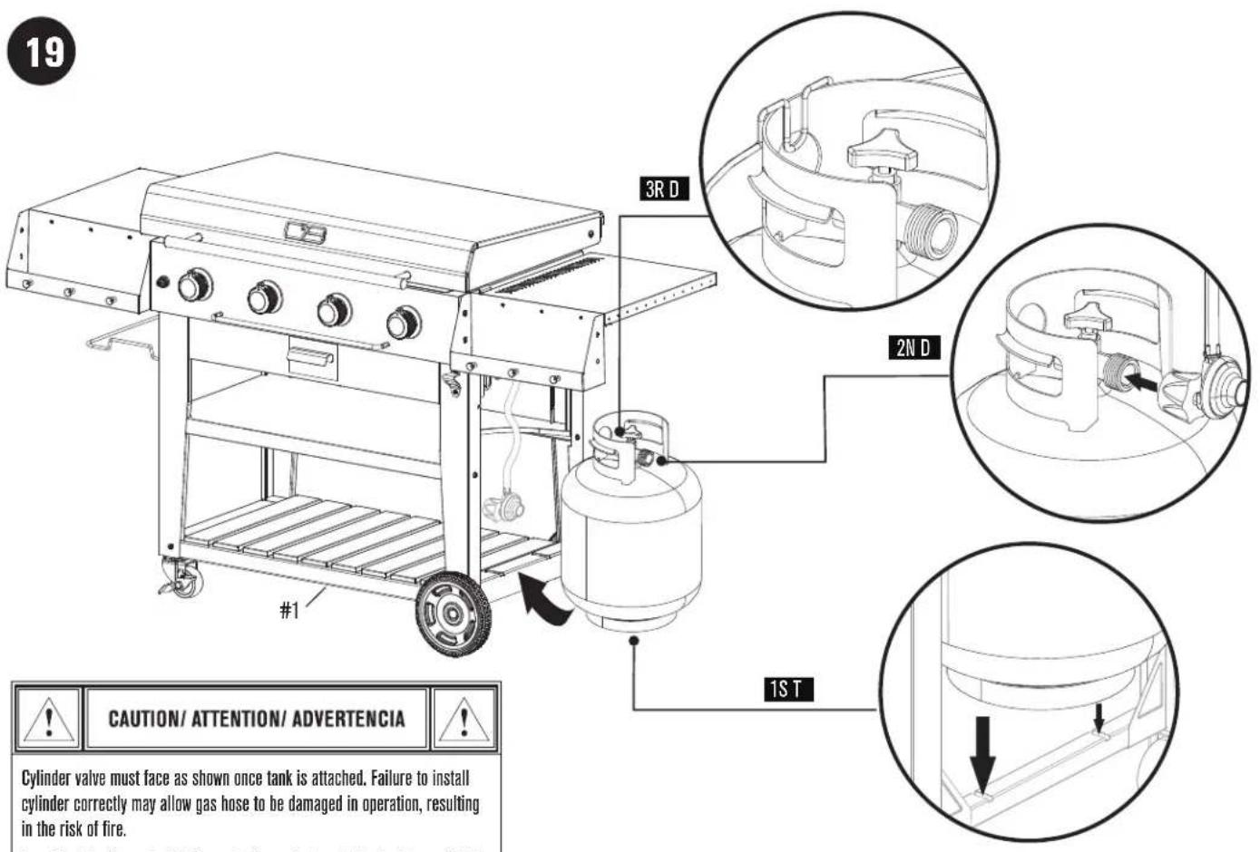

CAUTION/ ATTENTION/ ADVERTENCIA

Cylinder valve must face as shown once tank is attached. Failure to install cylinder correctly may allow gas hose to be damaged in operation, resulting in the risk of fire.
natural_image
Technical line drawing of a mechanical assembly with labeled components (no readable text or symbols)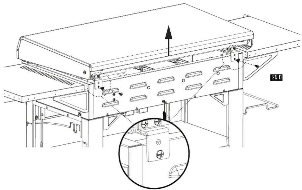
EMERGENCIES: If a gas leak cannot be stopped, or a fire occurs due to gas leakage, call the fire department.
| Emergencies Possible Cause Prevention/Solution | ||
| Gas leaking from cracked/cut/burned hose. | Damaged hose. | Turn off gas at LP cylinder or at source on natural gas systems. Discontinue use of product and replace valve/hose/regulator. Once valve/hose/regulator replaced conduct complete leak check per manual. |
| Gas leaking from LP cylinder. Gas leaking from LP cylinder valve. | Mechanical failure due to rusting or mishandling.Failure of cylinder valve from mishandling or mechanical failure. | Replace LP cylinder.Turn off LP cylinder valve. Return LP cylinder to gas supplier. |
| Gas leaking between LP cylinder and regulator connection. | Improper installation, connection not tight, and/or failure of rubber seal in cylinder valve. | Turn off LP cylinder valve. Remove regulator from cylinder and visually inspect rubber seal in cylinder valve for damage. If damage or cannot correct leak replace cylinder. See LP Cylinder Leak Test and Connecting Regulator to the LP Cylinder. |
| Fire coming through control panel. | Fire in burner tube section of burner due to blockage. | Turn off control knobs and LP cylinder valve. Leave lid open to allow flames to die down. After fire is cut and grill is cold, remove burner and inspect for spider nests or rust. See Natural Hazard and Cleaning the Burner Assembly pages. |
| Grease fire or continuous excessive flames above cooking surface. | Too much grease buildup in burner area. | Turn off control knobs and LP cylinder valve. Leave lid open to allow flames to die down. After cooling, clean food particles and excess grease from inside firebox area, grease tray, and other surfaces. |
Troubleshooting
| Problem Possible Cause Prevention/Solution | ||
| Burner(s) will not light using ignitor.(See Electronic Ignition Troubleshooting also)Continued on next page. | GAS ISSUES:Trying to light wrong burner.Burner not engaged with control valve.Obstruction in burner.No gas flow.Coupling nut and LP cylinder valve not fully connected.ELECTRICAL ISSUES:Electrode cracked or broken; “sparks at crack.”Electrode tip not in proper position.(Does not apply to SUREFIRE.)Wire and/or electrode covered with cooking residue.Wires are loose or disconnected.Wires are shorting (sparking) between ignitor and electrode.Dead battery.ELECTRONIC IGNITION:No spark, no ignition noise.No spark, some ignition noise.Sparks, but not at electrode or at full strength. | See instructions on control panel and in Use and Care section.Make sure valves are positioned inside of burner tubes.Ensure burner tubes are not obstructed with spider webs or other matter. See cleaning section of Use and Care.Make sure LP cylinder is not empty. If LP cylinder is not empty, refer to “Sudden drop in gas flow.”Turn the coupling nut approximately one-half to three-quarters additional turn until solid stop. Tighten by hand only - do not use tools.Replace electrode(s).Main Burners:Tip of electrode should be pointing toward gas port opening on burner. The distance should be 1/8" to 1/4". Adjust if necessary.Sideburner:Tip of electrode should be pointing toward gas port opening on burner. the distance should be 1/8" to 3/16". Adjust if necessary.Clean wire and/or electrode with rubbing alcohol and clean swab.Reconnect wires or replace electrode/wire assembly.Replace ignitor wire/electrode assembly.Replace with a new alkaline battery.See Section I of Electronic Ignition System.See Section II of Electronic Ignition System.See Section III of Electronic Ignition System. |
| Burner(s) will not match light. See | GAS ISSUES:Match will not reach.Improper method of match-lighting. | Use long-stem match (fireplace match).See "Match-Lighting" section of Use and Care. |
| Sudden drop in gas flow or low flame. | Out of gas.Excess flow valve tripped.Vapor lock at coupling nut/LP cylinder connection. | Check for gas in LP cylinder.Turn off knobs, wait 30 seconds and light grill. If flames are still low, turn off knobs and LP cylinder valve. Disconnect regulator. Reconnect regulator and leak-test. Turn on LP cylinder valve, wait 30 seconds and then light grill.Turn off knobs and LP cylinder valve. Disconnect coupling nut from cylinder. Reconnect and retry. |
| Flames blow out. • High or gusting winds.Low on LP gas.Excess flow valve tripped. | Turn front of grill to face wind or increase flame height by turning gas valve to a higher position.Refill LP cylinder.Refer to “Sudden drop in gas flow” above. | |
| Flare-up. • Grease buildup. | Excessive fat in meat.Excessive cooking temperature. | Clean burners and inside of grill/firebox.Trim fat from meat before grilling.Adjust (lower) temperature accordingly. |
| Persistent grease fire. | Grease trapped by food buildup around burner system. | Turn knobs to OFF. Turn gas off at LP cylinder. Leave lid in position and let fire burn out. After grill cools, remove and clean all parts. |
| Flashback (fire in burner tube(s)). | Burner and/or burner tubes are blocked. | Turn knobs to OFF. Clean burner and/or burner tubes. See burner cleaning section of Use and Care. |
| One burner does not light from other burner(s). | Grease buildup or food particles in end(s) of carryover tube(s). | Clean carry-over tube(s) with wire brush. |
Troubleshooting - Electronic Ignition
| Problem (Ignition) Possible Cause Check Procedure | Prevention/Solution | ||
| SECTION INo sparks appear at any electrodes when Electronic Ignition Button is pressed; no noise can be heard from spark module. | Battery not installed properly.Dead battery.Button assembly not installed properly.Faulty spark module. | Check battery orientation.Has battery been used previously?Check to insure threads are properly engaged. Button should travel up and down without binding.If no sparks are generated with new battery and good wire connections, module is faulty. | Install battery (make sure that "+" and "-" connectors are oriented correctly, with "+" on cap end.)Replace battery with new alkaline battery.Unscrew button cap assembly and reinstall, making sure threads are aligned and engaged fully.Replace spark module assembly. |
| SECTION IINo sparks appear at any electrodes when Electronic Ignition Button is pressed; noise can be heard from spark module. | Output lead connections not connected. | Are output connections on and tight? | Remove and reconnect all output connections at module and electrodes. |
| SECTION IIISparks are present but not at all electrodes and/or not at full strength | Output lead connections not connected.Arcing to grill away from burner(s).Weak battery.Electrodes are wet.Electrodes cracked or broken "sparks at crack". | Are output connections on and tight?If possible, observe grill in dark location. Operate ignition system and look for arcing between output wires and grill frame.All sparks present but weak or at slow rate.Has moisture accumulated on electrode and/or in burner ports?Inspect electrodes for cracks. | Remove and reconnect all output connections at module and electrodes.If sparks are observed other than from burner(s), wire insulation may be damaged. Replace wires.Replace battery with a new alkaline battery.Use paper towel to remove moisture.Replace cracked or broken electrodes. |
ACTIVATE YOUR WARRANTY
Scan QR code with your phone camera and register online.
ACTIVEZ VOTRE GARANTIE.
- FOR OUTDOOR USE ONLY
- POUR USAGE EN MILIEU EXTÉRIEUR UNIQUEMENT ESTE JUEGO SÓLO SE PUEDE USAR EXTERIORS
- TOOLS REQUIRED FOR ASSEMBLY:
- OUTILS REQUIS POUR L'ASSEMBLAGE:
- INSTALLER/ASSEMBLER:
- WARNING
- DANGER
- IMPORTANT SAFETY INFORMATION
- SAFETY SYMBOLS
- CAUTION
- If you smell gas:
- FOR YOUR SAFETY - INSTALLING YOUR GRILL
- Grease Fires
- OUTDOOR
- USE AND CARE
- Installation Safety Precautions
- LP Cylinder Removal, Transport and Storage
- LP Cylinder
- LP (Liquefied Petroleum Gas)
- LP Cylinder Filling
- LP Cylinder Exchange
- LP Cylinder Leak Test
- For your safety
- Connecting Regulator to the LP Cylinder
- NOTE:
- Leak Testing Valves, Hose and Regulator
- Safety Tips
- Battery
- LP GAS CYLINDER RUBBER SEAL INSPECTION.
- For Safe Use of Your Grill and to Avoid Serious Injury:
- Ignitor Lighting
- Match-Lighting
- Burner Flame Check
- Turning Grill Off
- Ignitor Check
- Valve Check
- Hose Check
- Storing Your Grill
- SPIDER ALERT!
- General Grill Cleaning
- Cleaning the Burner Assembly
- SEASONING
- WHAT IS SEASONING?
- WHAT OIL SHOULD I USE?
- MAINTENANCE
- GRIDDLE SURFACE- CLEANING
- FIRST TIME:
- AFTER EACH USE:
- GREASE CUP
- LIMITED WARRANTY
- ITEMS MANUFACTURER WILL NOT PAY FOR:
- DISCLAIMER OF IMPLIED WARRANTIES and LIMITATION OF REMEDIES
- TABLE DES MATIÈRES
- AVERTISSEMENT
- ATTENTION
- GRO ADVERTENCIA
- ADVERTENCIA
- PARTS LIST
- LISTE DES PIÈCES
- 4
- ASSEMBLY / ASSEMBLAGE / ASAMBLEA
- CAUTION/ ATTENTION/ ADVERTENCIA
Brand : Char-Broil
Model : Performance 463814225
Category : Grill plate