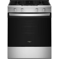
WSES3330TW - Cooker WHIRLPOOL - Free user manual and instructions
Find the device manual for free WSES3330TW WHIRLPOOL in PDF.

User questions about WSES3330TW WHIRLPOOL
0 question about this device. Answer the ones you know or ask your own.
Ask a new question about this device
Download the instructions for your Cooker in PDF format for free! Find your manual WSES3330TW - WHIRLPOOL and take your electronic device back in hand. On this page are published all the documents necessary for the use of your device. WSES3330TW by WHIRLPOOL.
USER MANUAL WSES3330TW WHIRLPOOL
Connected Appliances Only
RANGEMAINSTANCEANDCARE...5
General Cleaning.
Self-Cleaning Cycle (on some
models) 5
Steam Clean (on some models) 6
WipeClean™ Cooktop Coating
Cleaning Routine (On Some
Models) 7
INSTALLATIONINSTRUCTIONS
REQUIREMENTS 7
Tools and Parts 7
Location Requirements 7
Electrical Requirements - U.S.A.
Only. 10
Electrical Requirements - Canada
Only. 11
Oven light. 12
INSTALLATION 12
Unpack Range. 12
Install Anti-Tip Bracket 12
Verify Anti-Tip Bracket Is Installed
and Engaged 13
Adjust Leveling Legs 13
Level Range 14
Electrical Connection - U.S.A.
Only 14
StorageDrawer 19
Oven Door 20
Complete Installation. 20
Moving the Range. 21
SECURITE DE LA CUISINIÈRE 22
Programme Self-Cleaning
WipeCleanTM (sur certains
modles). 28
EXIGENCESD'INSTRUCTIONS
D'INSTALLATION 29
Specifications electrodes - Canada
seulement 32
Lampe du four 33
INSTALLATION 33
Ciclo de Self-Cleaning
Your safety and the safety of others are very important.
We have provided many important safety messages in this manual and on your appliance. Always read and obey all safety messages.

This is the safety alert symbol.
This symbol alerts you to potential hazards that can kill or hurt you and others.
All safety messages will follow the safety alert symbol and either the word "DANGER" or "WARNING." These words mean:
ADANGER
WARNING
All safety messages will tell you what the potential hazard is, tell you how to reduce the chance of injury, and tell you what can happen if the instructions are not followed.
You can be killed or seriously injured if you don't immediately follow instructions.
You can be killed or seriously injured if you don't follow instructions.
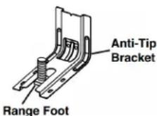
The range will not tip during normal use. However, the range can tip if you apply too much force or weight to the open door without having the anti-tip bracket fastened down properly.

WARNING
Tip Over Hazard
A child or adult can tip the range and be killed.
Install anti-tip bracket to floor or wall per installation instructions.
Slide range back so rear range foot is engaged in the slot of the anti-tip bracket.
Re-engage anti-tip bracket if range is moved.
Do not operate range without anti-tip bracket installed and engaged.
Failure to follow these instructions can result in death or serious burns to children and adults.
To verify the anti-tip bracket is properly installed and engaged:
- Slide range forward.
- Look for the anti-tip bracket securely attached to floor or wall.
- Slide range back so rear range foot is under the anti-tip bracket.
- See Installation Instructions for details.
IMPORTANT SAFETY INSTRUCTIONS
WARNING: To reduce the risk of fire, electric shock, or injury to persons when using the appliance, follow basic precautions, including the following:
WARNING: TO REDUCE THE RISK OF TIPPING OF THE RANGE, THE RANGE MUST BE SECURED BY PROPERLY INSTALLED ANTI-TIP DEVICES. TO CHECK IF THE DEVICES ARE INSTALLED PROPERLY, SLIDE RANGE FORWARD, LOOK FOR ANTI-TIP BRACKET SECURELY ATTACHED TO FLOOR OR WALL, AND SLIDE RANGE BACK SO REAR RANGE FOOT IS UNDER ANTI-TIP BRACKET.
WARNING: Danger of fire: Do not store items on the cooking surfaces. Never leave anything on the surface when unattended and not in use. Never place flammable or plastic items on or near the surface.
CAUTION: Do not store items of interest to children in cabinets above an appliance or on the backguard of an appliance - children climbing on the appliance to reach items could be seriously injured.
- Proper Installation - The appliance, when installed, must be electrically grounded in accordance with local codes, or in the absence of local codes, with the National Electrical Code, ANSI/NFPA 70 or the Canadian Electrical Code, CSA C22.1-02. In Canada, the appliance must be electrically grounded in accordance with Canadian Electrical Code. Be sure your appliance is properly installed and grounded by a qualified technician.
- Never Use Your Appliance for Warming or Heating the Room.
- Do Not Leave Children Alone - Children should not be left alone or unattended in area where appliance is in use. They should never be allowed to sit or stand on any part of the appliance.
Wear Proper Apparel - Loose-fitting or hanging garments should never be worn while using the appliance.
- User Servicing - Do not repair or replace any part of the appliance unless specifically recommended in the manual. All other servicing should be referred to a qualified technician.
Storage in or on Appliance - Flammable materials should not be stored in an oven or near surface units.
This appliance is not intended for storage.
■ Do Not Use Water on Grease Fires - Smother fire or flame or use dry chemical or foam-type extinguisher.
- Do not use replacement parts that have not been recommended by the manufacturer (e.g. parts made at home using a 3D printer).
Use Only Dry Potholders - Moist or damp potholders on hot surfaces may result in burns from steam. Do not let potholder touch hot heating elements. Do not use a towel or other bulky cloth.
- DO NOT TOUCH SURFACE UNITS OR AREAS NEAR UNITS - Surface units may be hot even though they are dark in color. Areas near surface units may become hot enough to cause burns. During and after use, do not touch, or let clothing or other flammable materials contact surface units or areas near units until they have had sufficient time to cool. Among these areas are the coil elements, the cooktop, and surfaces facing the cooktop.
Use Proper Pan Size - This appliance is equipped with one or more surface units of different size. Select utensils having flat bottoms large enough to cover the surface unit heating element. The use of undersized utensils will expose a portion of the heating element to direct contact and may result in ignition of clothing. Proper relationship of utensil to burner will also improve efficiency.
■ Never Leave Surface Units Unattended at Higher Heat Settings - Cooking oils and animal fats are flammable, boilover may cause smoking, and greasy spillovers may ignite.
Make Sure Reflector Pans or Drip Bowls Are in Place Absence of these pans or bowls during cooking may subject wiring or components underneath to damage.
- Protective Liners - Do not use aluminum foil to line surface unit drip bowls or oven bottoms, except as suggested in the manual. Improper installation of these liners may result in a risk of electric shock, or fire.
Glazed Cooking Utensils - Only certain types of glass, glass/ceramic, ceramic, earthenware, or other glazed utensils are suitable for range-top service without breaking due to the sudden change in temperature.
- Utensil Handles Should Be Turned Inward and Not Extend Over Adjacent Surface Units - To reduce the risk of burns, ignition of flammable materials, and spillage due to unintentional contact with the utensil, the handle of a utensil should be positioned so that it is turned inward, and does not extend over adjacent surface units.
Do Not Soak Removable Heating Elements - Heating elements should never be immersed in water.
- Do Not Cook on Broken Cook-Top - If cook-top should break, cleaning solutions and spillovers may penetrate the broken cook-top and create a risk of electric shock. Contact a qualified technician immediately.
Clean Cooktop With Caution - If a wet sponge or cloth is used to wipe spills on a hot cooking area, be careful to avoid steam burn. Some cleaners can produce noxious fumes if applied to a hot surface.
Use Care When Opening Door - Let hot air or steam escape before removing or replacing food.
- Do Not Heat Unopened Food Containers - Build-up of pressure may cause container to burst and result in injury.
- Keep Oven Vent Ducts Unobstructed.
- Placement of Oven Racks - Always place oven racks in hot desired location while oven is cool. If rack must be moved while oven is hot, do not let potholder contact hot heating or element in oven.
- DO NOT TOUCH HEATING ELEMENTS OR INTERIOR SURFACES OF OVEN - Heating elements may be hot even though they are dark in color. Interior surfaces of an oven become hot enough to cause burns. During and after use, do not touch, or let clothing or other flammable materials contact heating elements or interior surfaces of oven until they have had sufficient time to cool. Other surfaces of the appliance may become hot enough to cause burns - among these surfaces are oven vent openings and surfaces near these openings, oven doors, and windows of oven doors.
SAVE THESE INSTRUCTIONS
IMPORTANT SAFETY INSTRUCTIONS
Care must be taken to prevent aluminum foil and meat probes from contacting heating elements.
For self-cleaning ranges -
CAUTION: DO NOT LEAVE FOOD OR COOKING UTENSILS, ETC., IN OVEN DURING THE PYROLYTIC SELF-CLEANING MODE OF OPERATION.
- Do Not Clean Door Gasket - The door gasket is essential for a good seal. Care should be taken not to rub, damage or move the gasket.
- Do Not Use Oven Cleaners - No commercial oven cleaner or oven liner protective coating of any kind should be used in or around any part of the oven.
Clean Only Parts Listed in Manual.
Before Self-Cleaning the Oven - Remove broiler pan and other utensils.
For units with ventilating hood -
Clean Ventilating Hoods Frequently - Grease should not be allowed to accumulate on hood or filter.
■ When flaming foods under the hood, turn the fan on.
For smart enabled ranges and ovens
Remote operation - This appliance is configurable to allow remote operation at any time. Do not store any flammable materials or temperature sensitive items inside, on top or near surface units of the appliance.
SAVE THESE INSTRUCTIONS
Internet Connectivity Guide for Connected Appliances Only
IMPORTANT: Proper installation of your appliance prior to use is your responsibility. Be sure to read and follow the installation instructions that came with your appliance.
Connectivity requires Wi-Fi and account creation. App features and functionality are subject to change. Data rates may apply. Once installed, launch the app. You will be guided through the steps to set up a user account and to connect your appliance.
You Will Need:
A home wireless router supporting Wi-Fi, 2.4 Ghz with WPA2 security. If you are unsure of your router's capabilities, refer to the router manufacturer's instructions.
The router to be on and have a live internet connection.
The 10-character SAID code for your appliance. The SAID code is either printed on a label on the appliance or found on the LCD screen.
Federal Communications Commission (FCC) Compliance Notice
This device complies with Part 15 of the FCC Rules. Operation is subject to the following two conditions:
- This device may not cause harmful interference, and
- This device must accept any interference received, including interference that may cause undesired operation.
Changes or modifications not expressly approved by the party responsible for compliance could void the user's authority to operate the equipment.
Industry Canada (IC) Compliance Notice
This Device complies with Industry Canada License-exempt RSS standard(s). Operation is subject to the following two conditions:
- This device may not cause interference.
- This device must accept any interference, including interference that may cause undesired operation of the device.
Under Industry Canada regulations, this radio transmitter may only operate using an antenna of a type and maximum (or lesser) gain approved for the transmitter by Industry Canada. To reduce potential radio interference to other users, the antenna type and its gain should be so chosen that the equivalent isotropically radiated power (e.i.r.p.) is not more than that necessary for successful communication.
To comply with FCC and Industry Canada RF radiation exposure limits for general population, antenna(s) used for this transmitter must be installed such that a minimum separation distance of 20~cm is maintained between the radiator (antenna) and all persons at all times and must not be co-located or operating in conjunction with any other antenna or transmitter.
If this equipment does cause harmful interference to radio or television reception, which can be determined by turning the equipment off and on, the user is encouraged to try to correct the interference by one of the following measures:
Reorient or relocate the receiving antenna.
■ Increase the separation between the equipment and receiver.
- Connect the equipment into an outlet on a circuit different from that to which the receiver is connected.
■ Consult the dealer or an experienced radio/TV technician for help.
RANGE MAINTENANCE AND CARE
General Cleaning
IMPORTANT: Before cleaning, make sure all controls are off and the oven and cooktop are cool. Always follow label instructions on cleaning products.
Soap, water, and a soft cloth or sponge are suggested first, otherwise noted.
EXTERIOR PORCELAIN ENAMEL SURFACES (on some models)
Food spills containing acids, such as vinegar and tomato, should be cleaned as soon as the entire range is cool. These spills may affect the finish.
Cleaning Method:
Glass cleaner, mild liquid cleaner, or nonabrasive scrubbing pad: Gently clean around the model/serial/rating plate because scrubbing may remove numbers.
■ Affresh ® Kitchen and Appliance Cleaner Part Number W10355010 (not included): See the Quick Start Guide for contact information.
STAINLESS STEEL (on some models)
NOTE: To avoid damage to stainless steel surfaces, do not use soap-filled scouring pads, abrasive cleaners, Cooktop Cleaner, steel-wool pads, gritty washcloths, or abrasive paper towels. Damage may occur to stainless steel surfaces, even with one-time or limited use.
Cleaning Method:
Rub in direction of grain to avoid damaging.
■ Affresh® Stainless Steel Cleaner Part Number W10355016 (not included):
See the Quick Start Guide for contact information.
METALLIC PAINT (on some models)
Do not use abrasive cleaners, cleaners with bleach, rust removers, ammonia, or sodium hydroxide (lye) because paint surface may stain.
CERAMIC GLASS COOKTOP CLEANING
Cleaning Method:
IMPORTANT: Cooktop scrapers may damage the coating and potentially diminish cleaning performance.
- Ensure that the cooktop has cooled to room temperature.
- Cover food/residue with water for a minimum of 5 minutes. Ensure coverage over the entire affected area.
- Wipe with a non-abrasive sponge.
NOTE: If water dries or food/residue persists on the cooking surface, repeat Steps 2 and 3.
COOKTOP CONTROLS
To avoid damage to the cooktop controls, do not use steel wool or abrasive cleansers, or oven cleaner.
To avoid damage, do not soak knobs. When replacing knobs, make sure knobs are in the Off position.
On some models, do not remove seals under knobs.
Cleaning Method:
- Soap and water: Pull knobs straight away from control panel to remove.
CONTROL PANEL AND OVEN DOOR EXTERIOR
To avoid damage to the control panel, do not use abrasive cleaners, steel-wool pads, gritty washcloths, or abrasive paper towels.
Cleaning Method:
Glass cleaner and soft cloth or sponge: Apply glass cleaner to soft cloth or sponge, not directly on panel.
■ Affresh 假 Kitchen and Appliance Cleaner Part Number W10355010 (not included):
See the Quick Start Guide for contact information.
OVEN RACKS
Cleaning Method:
Steel-wool pad
For racks that have discolored and are harder to slide, a light coating of vegetable oil applied to the rack guides will help them slide.
Dishwasher (steam rack water reservoir only, not racks):
Although the water reservoir is durable, it may lose its shine and/or discolor when washed in a dishwasher.
STORAGE DRAWER
Check that storage drawer is cool and empty before cleaning.
Cleaning Method:
Mild detergent
OVEN CAVITY
Depending on your model, use Steam Clean or Self-Clean Cycle regularly to clean oven spills.
eDo not use oven cleaners.
Food spills should be cleaned when oven cools. At high temperatures, foods react with porcelain. Staining, etching, pitting, or faint white spots can result.
Cleaning Method:
Clean cycle: See "Clean Cycle" first.
Self-Cleaning Cycle (on some models)

AWARNING
Burn Hazard
Do not touch the oven during the Self-Cleaning cycle. Keep children away from the oven during Self-Cleaning cycle.
Failure to follow these instructions can result in burns.
IMPORTANT: The health of some birds is extremely sensitive to the fumes given off during the Self-Cleaning cycle. Exposure to the fumes may result in death to certain birds. Always move birds to another closed and well-ventilated room.
Keep the kitchen well-ventilated during the Self-Cleaning cycle to help get rid of heat, odors, and smoke.
Do not block the oven vent(s) during the Self-Cleaning cycle. must be able to move freely. Depending on your model, see Vent" or "Oven Vents" section in your Quick Start Guide.
A.Oven vent
Do not clean, rub, damage, or move the oven door gasket.
Prepare Range:
- Remove the broiler pan, grid, cookware and bakeware, all cooking utensils, oven racks, aluminum foil, and, on some models, the temperature probe from the oven.
Use a damp cloth to clean inside door edge and/the 1 (3.8 cm) area around the inside oven cavity frame, being certain not to move or bend the gasket.
Wipe out any loose soil to reduce smoke and avoid damage. At high temperatures, foods react with porcelain. Staining, etching, pitting, or faint white spots can result. This will not affect cooking performance. - Remove plastic items from the cooktop because they may melt.
Remove all items from the storage drawer.
How the Cycle Works
IMPORTANT: The heating and cooling of porcelain on steel in the oven may result in discoloring, loss of gloss, hairline cracks, and popping sounds.
The Self-Cleaning cycle uses very high temperatures, burning soil to a powdery ash.
Once the oven has completely cooled, remove ash with a damp cloth. To avoid breaking the glass, do not apply a cool damp cloth to the inner door glass before it has completely cooled.
To stop the Self-Cleaning cycle at any time, press CANCEL or OFF/CANCEL. If the temperature is too high, the oven door will remain locked and a message appears on the screen regarding oven cooling and "O" icon will be displayed.
When "O" shows in the display, the door of the oven cannot be opened. To avoid damage to the door, do not force the door open when "O" is displayed.
Before self-cleaning, make sure the door is completely closed on the door will not lock and the Self-Cleaning cycle will not begin.
Once the cleaning temperature has been reached, the electronic control requires a 24 hour delay before another Self-Cleaning cycle can be started.
The oven light will not function during the Self-Cleaning cycle.
Electronic Oven Control with Adjustable Clean Time (on some models)
The Self-Cleaning cycle is time adjustable between 2 hours and 4 hours. Suggested clean times are 2 hours for light soil, 3 hours for medium soil, and 4 hours for heavy soil. The door will unlock once the oven cools.
AiMPORTANT: When cooktop is in use, the Self-Cleaning cycle will "Obendisabled. When the Self-Cleaning cycle is in use, the cooktop will be locked.
To Self-Clean:
- Press CLEAN SELF/STEAM.
- Press the < or > to select cleaning type.
- Press CONFIRM/MENU.
- Press the < or > to select cleaning duration.
-
Press CONFIRM/MENU.
-
Press START.
NOTE: The oven door will automatically lock. The Door Locked and Clean indicator lights will be displayed. The time remaining will also be displayed.
- When the Self-Cleaning cycle is complete and the oven cools, the Door Locked and Clean indicator lights will turn off.
- When the oven is completely cooled, remove ash with a damp cloth.
NOTE: To exit the Self-Cleaning cycle before completed, press CANCEL or OFF/CANCEL. The door will unlock once the oven cools.
Steam Clean (on some models)
IMPORTANT: Do not use oven cleaners or any other additives with Steam Clean.
The Steam Clean feature is designed for light oven cavity bottom cleaning. Use the Steam Clean feature as soon as possible after spills occur. The longer a spill sits and dries in the oven, the more difficult it may be to remove.
Allow the range to cool to room temperature before using the Steam Clean feature.
Remove all racks and accessories from the oven cavity.
For best results, pour 12 oz (355 mL) of distilled or filtered water onto the oven bottom.
The Steam Clean feature will take a total of 40 minutes. "End" will appear in the display at the end of the cycle.
IMPORTANT: Since the water in the oven bottom is hot, do not open the oven door during the Steam Clean cycle.
Press the Cancel keypad at any time to end the cycle. The display will return to the time of day.
Helpful Hints
Once the Steam Clean cycle is complete, remove all remaining water and debris in the bottom of the oven with a sponge or cloth.
■ Wipe any remaining moisture from the oven door interior, oven cavity interior sides, and cooktop.
- Use a soft brush or nylon scrubber to wipe the oven interior. This may help with more stubborn stains.
If any soil remains, run a second Steam Clean cycle to help loosen debris for easier removal.
Use the Steam Clean on small spills such as cheese or sauce from pizza or snacks, or drips from casseroles.
- Food spills containing sugar, proteins or starches may require vigorous scrubbing to remove most of the debris.
It is recommended to use distilled or filtered water, as tap water may leave mineral deposits on the oven bottom. Use a cloth soaked with vinegar or lemon juice to remove any mineral deposits that may be left after the Steam Clean cycle.
WipeClean™ Cooktop Coating Cleaning Routine (On Some Models)
IMPORTANT: Clean the cooktop according to these instructions after each use to avoid soil build ups and to prolong the life of your WipeClean™ Cooktop.
Everyday Cleaning:
- Allow the cooktop to cool down completely before proceeding
- Spray the cooktop with water and soak for a minimum of 5 minutes, paying attention to cover the entire soiled area. heavy stains, soak for 20-25 minutes.
- Using a paper or kitchen towel remove the initial layer of soil from the surface.
- Use a moist non-abrasive soft sponge and scrub the residual soil from the surface.
- With a paper or kitchen towel wipe off and dry the surface.
- Repeat steps 2 through 5 as necessary for stubborn soils.
Extremely Tough Soils:
- For extremely heavy soils, increase the amount of time soaking in water up to 45 minutes.
- If an extremely tough soil persists, apply a few dime-sized drops of a non abrasive cooktop cleaner such as the affresh® Cooktop Cleaner to the affected areas to remove the remaining soil from the surface. Gently apply the cleaner with a paper towel.
Wipe away the cleaner with a warm damp cloth after using any detergent.
Use of a scraper is not recommended as it might cause potential cooktop scratches.
- Important: Do not apply excessive pressure while using detergents and do not use coarse or abrasive sponges with them. Detergents containing aggressive particles may damage your cooktop.
Tips & Tricks
Detergents may contain abrasive particles or harsh chemicals: pay attention to detergent's type when cleaning and do not let them sit on the surface for more than 10 minutes. Avoid these items when it comes to cleaning your glass top stove:
- Steel wool and other scrubby, abrasive or course sponges
- Abrasive powder cleansers or abrasive detergents
- Chlorine bleach
Rust remover
Ammonia
Glass window cleaners
Light discoloration on the surface may happen if not cleaning frequently and cooking for a long time or cooking over a soi surface: they usually do not compromise cleanliness and surface properties.
Soaking with water will give the best results on cleaning: longer soaking times will increase cleanliness efficiency and result, preserving cooktop surface over time.
- Do not slide pots on the surface or use it as a cutting board. Small scratches on the surface may appear over normal use, as in standard glass, without compromising its performance.
- Avoid soiling build up on the surface as it can damage your product surface. Clean the cooktop surface after every spill, this will help preserve the cooktop surface over time.
INSTALLATION INSTRUCTIONS REQUIREMENTS
Tools and Parts
Gather the required tools and parts before starting installation. Read and follow the instructions provided with any tools listed here.
Tools needed
Tape measure
Flat-blade screwdriver
■ Phillips screwdriver
Level
Hammer
Hand or electric drill
Wrench or pliers
Marker or pencil
■ Flashlight
Torque Wrench
Masking tape
1/4" (6.4 mm) drive ratchet
1/4" (6.4 mm) nut driver
3/8" (9.5 mm) and 5/16" (8 mm) nut driver
1/8" (3.2 mm) drill bit (for wood floors)
Tin snips or large wire cutters (for cutting ground-link strap if necessary)
Parts supplied
Check that all parts are included.
10-32 hex nuts (attached to terminal block) (3)
Direct wire lugs (3)
■ #10 x ½" (4.1 cm) screws (for mounting anti-tip bracket) (2)
Anti-tip bracket (inside oven cavity)
Anti-tip bracket must be securely mounted to the back wall or floor. Thickness of flooring may require longer screws to anchor bracket to subfloor. Longer screws are available from your local hardware store.
Parts needed
If using a power supply cord kit:
A UL listed power supply cord kit marked for use with ranges. The cord should be rated at 250V minimum, 40 A or 50 A that is marked for use with nomin"1(3.5 cm) diameter
use connection opening and must end in ring terminals or open-end spade terminals with upturned ends.
A UL listed strain relief.
Check local codes. Check existing electrical supply. See the appropriate "Electrical Requirements" section.
It is recommended that all electrical connections be made by a licensed, qualified electrical installer.
NOTE: Be sure to purchase only Whirlpool factory-certified parts and accessories for your appliance. Your installation may require additional parts. To order, refer to the contact information referenced in your Quick Start Guide.
Location Requirements
IMPORTANT: Observe all governing codes and ordinances.
It is the installer's responsibility to comply with installation clearances specified on the model/serial/rating plate. The model/serial/rating plate is located behind the oven door on the top right-hand side of the oven frame.
To eliminate the risk of burns or fire by reaching over the heated surface units, cabinet storage space located above the surface units should be avoided. If cabinet storage is to be provided, the risk can be reduced by installing a range hood or microwave hood combination that projects horizontally a minimum of 5^ (12.7 cm) beyond the bottom of the cabinets.
The range should be located for convenient use in the kitchen.
- Recessed installations must provide complete enclosure of the sides and rear of the range.
■ All openings in the wall or floor where range is to be installemobile Home - Additional Installation Requirements
must be sealed.
Cabinet opening dimensions that are shown must be used. Given dimensions are minimum clearances.
The anti-tip bracket must be installed. To install the anti-tip bracket shipped with the range, see the "Install Anti-Tip Bracket" section.
Grounded electrical supply is required. See the appropriate "Electrical Requirements" section.
- Contact a qualified floor covering installer to check that the floor covering can withstand at least 200^ (93^) .
Use an insulated pad or 1/4'' (6.4 mm) plywood under range installing range over carpeting.
IMPORTANT: To avoid damage to your cabinets, check with your builder or cabinet supplier to make sure that the materials used will not discolor, delaminate, or sustain other damage. This oven has been designed in accordance with the requirements of UL and CSA International and complies with the maximum allowable wood cabinet temperatures of 194^ (90^) .
Mobile Home - Additional Installation Requirements
The installation of this range must conform to the Manufactured Home Construction and Safety Standard, Title 24 CFR, Part 3280 (formerly the Federal Standard for Mobile Home Construction and Safety, Title 24, HUD Part 280). When such standard is not applicable, use the Standard for Manufactured Home Installations, ANSI A225.1/NFPA 501A or with local codes.
In Canada, the installation of this range must conform with the current standards CAN/CSA-Z240.1-latest edition, or with local codes.
Mobile Home Installations Require:
When this range is installed in a mobile home, it must be secured to the floor during transit. Any method of securing the floor range is adequate as long as it conforms to the standards listed above.
Four-wire power supply cord or cable must be used in a mobile home installation.
Cabinet Dimensions
Cabinet opening dimensions shown are for 25" (64.0 cm) countertop depth, 24" (61.0 cm) base cabinet depth and 36" (91.4 cm) countertop height.
IMPORTANT: If installing a range hood or microwave hood combination above the range, follow the range hood or microwave hood combination installation instructions for dimensional clearances above the cooktop surface.
Range may be installed next to combustible walls with zero clearance.
NOTE: When installed in a slide-in cutout, the front of oven door may protrude beyond the base cabinet.
Slide-In Cutout Freestanding Cutout
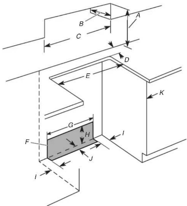
A. For minimum clearance to top of cooktop, see NOTE*.
B. 13'' (33 cm) maximum upper cabinet depth
C. 30^ (76.2 cm) minimum opening width
D. Remaining counter depth should not exceed 214 (5.7 cm).
E. In U.S.A. and Canada: 30^ (76.2 cm) minimum opening width
F. The shaded area is recommended for installation of grounded outlet.
G.13 % (33.3cm)
H. 7 / 16'' (19.5 cm)
1. 4'Y16" (12.2 cm)
J. 3^1 / 16 (9.4 cm) plus measurement of L
K. Cabinet door or hinges should not extend into the cutout.
A. For minimum clearance to top of cooktop, see NOTE*.
B. 13'' (33 cm) maximum upper cabinet depth
C. 30^ (76.2 cm) minimum opening width
D. Cabinet door or hinges should not extend into the cutout.
E. In U.S.A. and Canada: 30^ (76.2 cm) minimum opening width
F. The shaded area is recommended for installation of grounded outlet.
G.13 % (33.3cm)
H. 71% 16" (19.5 cm)
1. 4^_16^ (12.2cm)
J. 3^11 / 16 (9.4 cm)
*NOTE: 24" (61.0 cm) minimum when bottom of wood or metal cabinet is shielded by not less than 1 / 4'' (0.64 cm) flame retardant millboard covered with not less than No. 28 MSG sheet steel, 0.015" (0.4 mm) stainless steel, 0.024" (0.6 mm) aluminum or 0.020" (0.5 mm) copper.
30^ (76.2 cm) minimum clearance between the top of the cooking platform and the bottom of an uncovered wood or metal cabinet.
Electrical Requirements - U.S.A. Only
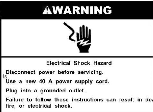
AWARNING

Electrical Shock Hazard
Electrically ground appliance.
Failure to do so could result in death, fire, or electrical shock.
If codes permit and a separate ground wire is used, it is recommended that a qualified electrical installer determine that the ground path and wire gauge are in accordance with local codes.
Do not use an extension cord.
Be sure that the electrical connection and wire size are adequate and in conformance with the National Electrical Code, ANSI/NFPA 70-latest edition and all local codes and ordinances.
A copy of the above code standards can be obtained from: National Fire Protection Association
1 Batterymarch Park Quincy, MA 02169-7471
WARNING: Improper connection of the equipment-grounding conductor can result in a risk of electric shock. Check with a qualified electrician or service technician if you are in doubt as to whether the appliance is properly grounded. Do not modify the power supply cord plug. If it will not fit the outlet, have a proper outlet installed by a qualified electrician.
Electrical Connection
To properly install your range, you must determine the type of electrical connection you will be using and follow the instructions provided for it here.
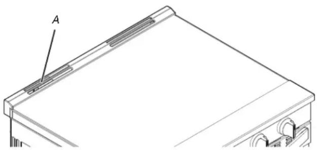
- Range must be connected to the proper electrical voltage and frequency as specified on the model/serial/rating plate. The model/serial/rating plate is located behind the oven door on the top right-hand side of the oven frame.
A. Model/serial/rating plate (located behind the oven door on the top right-hand side of the oven frame)
This range is manufactured with the neutral terminal connected to the cabinet. Use a 3-wire, UL listed, 40 or 50 A power supply cord (pigtail). See the following Range Rating chart. If local codes do not permit ground through the neutral, use a 4-wire power supply cord rated at 250V , 40 or 50 A and investigated for use with ranges.
Range Rating* Specified Rating of
Power Supply Cord Kit and Circuit Protection
120/240 V 120/208 V Ampere
8.8-16.5 kW 7.8-12.5 kW 40 or 50^**
16.6-22.5 kW 12.6-18.5 kW 50^**
*The NEC calculated load is less than the total connected load listed on the model/serial/rating plate.
**For 50 A rated cord kits, use kits that specify use with a nominal 13/8'' (34.9 mm) diameter connection opening.
A circuit breaker is recommended.
The range can be connected directly to the circuit breaker box (or fused disconnect) through flexible or nonmetallic sheathed, copper or aluminum cable. See the "Electrical Connection - U.S.A. Only" section.
- Allow at least 6 ft (182.9 cm) of slack in the line so that the range can be moved if servicing is ever necessary.
A UL Listed conduit connector must be provided at each end of the power supply cable (at the range and at the junction box).
Wire sizes and connections must conform with the rating of the range.
If connecting to a 3-wire system:
Local codes may permit the use of a UL listed, 3-wire, 250V or 50A range power supply cord (pigtail). This cord contains 3 copper conductors with ring terminals or open-end spade terminals with upturned ends, terminating in a NEMA Type 10-50 plug on the supply end. Connectors on the appliance end must be provided at the point the power supply cord enters the appliance. This uses a 3-wire receptacle of NEMA Type 10-50R.
3-wire receptacle (10-50R)
If connecting to a 4-wire system:
This range is manufactured with the ground connected to the neutral by a link. The ground must be revised so the green gro wire of the 4-wire power supply cord is connected to the cabinet. See "Electrical Connection - U.S.A. Only" section.
Grounding through the neutral conductor is prohibited for new branch-circuit installations (1996 NEC); mobile homes; and recreational vehicles, or an area where local codes prohibit grounding through the neutral conductor.
When a 4-wire receptacle of NEMA Type 14-50R is used, a matching UL listed, 4-wire, 250V 40 or 50 A, range power sup cord (pigtail) must be used. This cord contains 4 copper conductors with ring terminals or open-end spade terminals with A upturned ends, terminating in a NEMA Type 14-50P plug on the supply end.
The fourth (grounding) conductor must be identified by a green or green/yellow cover and the neutral conductor by a white cover. Cord should be Type SRD or SRDT with a UL listed strain relief and be at least 4 ft (1.22m) long.

4-wire receptacle (14-50R)
The minimum conductor sized for the copper 4-wire power cord are:
40 A circuit
2 No.-8 conductors
1 No.-10 white neutral
1 No.-10 green grounding
Electrical Requirements - Canada Only
If codes permit and a separate ground wire is used, it is recommended that a qualified electrical installer determine that the ground path is adequate and wire gauge are in accordance with local codes.
Be sure that the electrical connection and wire size are adequate and in conformance with CSA Standard C22.1, Canadian Electrical Code, Part 1 - latest edition, and all local codes and ordinances.
A copy of the above code standards can be obtained from:
San Standards Association
178 Rexdale Blvd.
Toronto, ON M9W 1R3 CANADA
- Check with a qualified electrical installer if you are not sure the ef range is properly grounded.
Range Rating* Specified Rating of
Power Supply Cord
Kit and Circuit
Protection
120/240 V 120/208 V Ampere
8.8-16.5 kW 7.8-12.5 kW 40 or 50^**
16.6-22.5 kW 12.6-18.5 kW 50**
*The NEC calculated load is less than the total connected load listed on the model/serial/rating plate. **For 50 A rated cord kits, use kits that specify use with a nominal 1 / 8" (34.9 mm) diameter connection opening.
- When a 4-wire, single phase 250V , 60Hz , AC-only electrical supply is available, a 40 A minimum circuit protection is required on 30^ (76.2 cm) ranges, fused on both sides of the line.
A circuit breaker is recommended.
This range is equipped with a UL or CSA International Certified Power Cord intended to be plugged into a standard 14-50R wall receptacle. Be sure the wall receptacle is within reach of range's final location.

Do not use an extension cord.
Oven Light
The oven light is a 40 W halogen bulb. Before replacing, make sure the oven and cooktop are cool and the control knobs are in the Off position.
To Replace:
- Disconnect power.
- Turn the glass bulb cover in the back of the oven counterclockwise to remove.
- Remove bulb from socket.
- Replace bulb, using tissue or wearing cotton gloves to handle bulb. To avoid damage to or decreasing the life of the new bulb, do not touch bulb with bare fingers.
- Replace bulb cover by turning clockwise.
- Reconnect power.
IMPORTANT: Do not use lamps rated higher than 40 W.
INSTALLATION
Unpack Range
AWARNING
Excessive Weight Hazard
Use two or more people to move and install or uninstall appliance.
Failure to do so can result in back or other injury.
- Remove shipping materials, tape and film from the range. Keep cardboard bottom under range. Do not dispose of anything until the installation is complete.
- Remove oven racks and parts package from oven and shipping materials.
- To remove cardboard bottom, first take 4 cardboard corners from the carton. Stack one cardboard corner on top of another. Repeat with the other 2 corners. Place them lengthwise on the floor behind the range to support the range when it is laid on its back.
- Using 2 or more people, firmly grasp the range and gently lay it on its back on the cardboard corners.
- Remove cardboard bottom.
The leveling legs can be adjusted while the range is on its back. See the "Adjust Leveling Legs" section.
NOTE: To place range back up into a standing position, put a sheet of cardboard or hardboard on the floor in front of range to protect the flooring. Using 2 or more people, stand range back up onto the cardboard or hardboard.
Install Anti-Tip Bracket
AWARNING

Tip Over Hazard
A child or adult can tip the range and be killed.
Install anti-tip bracket to floor or wall per installation instructions.
Slide range back so rear range foot is engaged in the slot of the anti-tip bracket.
Re-engage anti-tip bracket if range is moved.
Do not operate range without anti-tip bracket installed and engaged.
Failure to follow these instructions can result in death or serious burns to children and adults.
- Remove the anti-tip bracket from the inside of the oven.
- Determine which mounting method to use: floor or wall. If you have a stone or masonry floor, you can use the wall mounting method. If you are installing the range in a mobile home, you must secure the range to the floor. This anti-tip bracket and screws can be used with wood or metal studs.
- Determine and mark centerline of the cutout space. The mounting can be installed on either the left-side or right-side of the cutout. Position mounting bracket against the wall in the cutout so that the V-notch of the bracket 1 / 8 (32.8cm) from centerline as shown.
A. 1212'' (31.8 cm)
B. Bracket V-notch
C. Centerline
- Drill two 1/8 (3 mm) holes that correspond to the bracket holes of the determined mounting method. See the following illustrations.
Floor Mounting
Rear Position Front Position Diagonal (2 options)
Wall Mounting
- Using the two # 10 /8! (4.1 cm) Phillips-head screws provided, mount anti-tip bracket to the wall or floor.
- Move range close enough to opening to allow for final electrical connections. Remove shipping base, cardboard or hardboard from under range.
- Move range into its final location, making sure rear leveling slides into anti-tip bracket.
- Move range forward onto shipping base, cardboard or hardboard to continue installing the range using the following installation instructions.
Verify Anti-Tip Bracket Is Installed and Engaged
On Ranges Equipped with a Storage Printer:
- Slide range into final location, making sure rear leveling leg slides into anti-tip bracket.
- Remove the premium storage drawer. See the "Storage Drawer" section.
- Use a flashlight to look underneath the bottom of the range.
- Visually check that the rear range foot is inserted into the slot of the anti-tip bracket.
Adjust Leveling Legs
- If range height adjustment is necessary, use a wrench or pliers to loosen the four leveling legs.
This may be done with the range on its back or with the range supported on two legs after the range has been placed back to a standing position.
NOTE: To place range back up into a standing position, put a sheet of cardboard or hardboard in front of range. Using two or more people, stand range back up onto the cardboard or hardboard.
AWARNING

Tip Over Hazard
A child or adult can tip the range and be killed.
Install anti-tip bracket to floor or wall per installation instructions.
Slide range back so rear range foot is engaged in the slot of the anti-tip bracket.
Re-engage anti-tip bracket if range is moved.
gDo not operate range without anti-tip bracket installed and engaged.
Failure to follow these instructions can result in death or serious burns to children and adults.
- Measure the distance from the top of the counter to the floor.
- Measure the distance from the top of the cooktop to the bottom of the leveling legs. This distance should be the same. If it is not, adjust the leveling legs to the correct height. The leveling legs can be loosened to add up to a maximum of 1" (2.5 cm). A minimum of 3/16 (5 mm) is needed to engage the anti-tip bracket.
NOTE: If height adjustment is made when range is standing, tilt the range back to adjust the front legs, and then tilt forward to adjust the rear legs.
- When the range is at the correct height, check that there is adequate clearance under the range for the anti-tip bracket. Before sliding range into its final location, check that the anti-tip bracket will slide under the range and onto the rear leveling leg prior to anti-tip bracket installation.
NOTE: If a Trim Kit will be used, the top of the cooktop should be higher than the counter. See the Installation Instructions included with the Trim Kit for the correct height.
Level Range
Determine if you have Steam Clean by referring to the "Range Maintenance and Care" section.
For Ranges with Steam Clean:
- Place level on the oven bottom as indicated in one of the tw figures below depending on the size of the level. Check with the level: side to side and front to back.
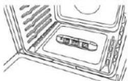
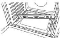
- If range is not level, pull range forward until rear leveling leg removed from the anti-tip bracket.
- Follow the directions in Style 1.
For Ranges without Steam Clean:
- Place a standard flat rack in oven.
- Place level on the rack and check levelness of the range, fir side to side; then front to back.
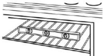
- If range is not level, pull range forward until rear leveling leg is removed from the anti-tip bracket.
- Follow the directions in Style 1.
Style 1: Ranges Equipped with a Storage Printer
Use a 1/4" drive ratchet, wrench or pliers to adjust leveling legs up or down until the range is level. Push range back into position. Check that rear leveling leg is engaged in the anti-tip bracket.
Electrical Connection - U.S.A. Only
Power Supply Cord
-
Disconnect power.
-
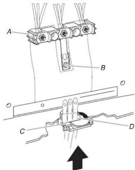
Remove the terminal block cover screws located on the back of the range. Pull cover down and toward you to remove cover from range.
A. Terminal block cover
B. Screws (2)
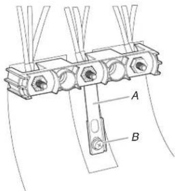
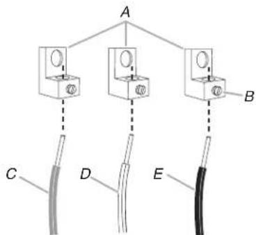
- Remove the three 10-32 hex nuts from the terminal posts.
A. 10-32 hex nuts
B. Terminal Posts
C. Ground Strap
- Add strain relief.
Style 1: Power supply cord strain relief
Remove the knockout for the power supply cord.
■ Assemble a UL listed strain relief in the opening.
A. UL listed strain relief
Tighten strain relief screw against the power supply cord.
Style 2: Direct wire strain relief
Remove the knockout as needed for the flexible conduit connection.
■ Assemble a UL listed conduit connector in the opening.
A. Removable retaining nut
B. Conduit
- Tighten strain relief screw against the flexible conduit.
- Complete installation following instructions for your type of electrical connection:
4-wire (recommended)
3-wire (if 4-wire is not available)
Electrical Connection Options
| If your home has: | And you will be connecting to: | Go to Section: |
| 4-wire receptacle (NEMA type 14-50R) | A UL Listed, 250 V4-wire minimum, 40 A, range power supply cord | V4-wire connection: Power supply cord |
4-wire direct
A. 3 / 8'' (1 cm)
B. 5'' (12 cm)
3-wire receptacle (NEMA type 10-50R)
A UL Listed, 250 minimum, 40 A, range power supply cord
4-wire connection: Direct wire
V3-wire connection: Power supply cord
3-wire direct
A circuit breaker box or fused disconnect
3-wire connection: Direct wire
A. 3 / 8'' (1 cm)
B. 3''(7.6 ~cm)
4-Wire Connection: Power Supply Cord
Use this method for:
New branch-circuit installations (1996 NEC)
Mobile homes
Recreational vehicles
In an area where local codes prohibit grounding through the neutral
- Part of metal ground strap must be cut out and removed.
A. Metal ground strap
B. Ground-link screw
- Use a Phillips screwdriver to remove the ground-link screw from the back of the range. Save the ground-link screw and the end of the ground link under the screw.
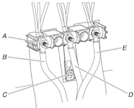
- Feed the power supply cord through the strain relief on the cord/conduit plate on bottom of range. Allow enough slack to easily attach the wiring to the terminal block.
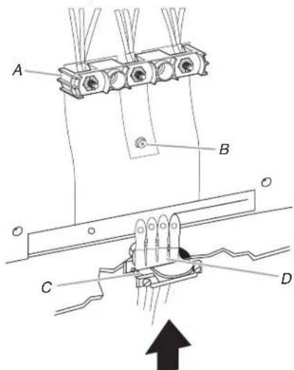
A. Terminal block
C. UL listed strain relief
B. Ground-link
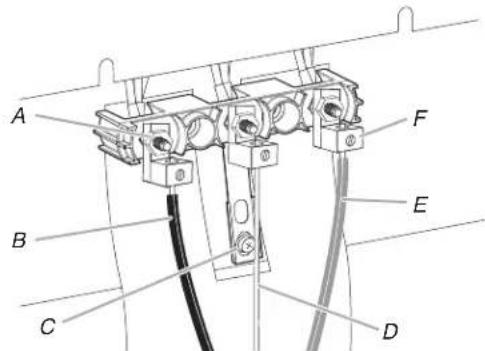
D. Power supply cord wires
-
Use Phillips screwdriver to connect the green ground wire from the power supply cord to the range with the ground-link screw. The ground wire must be attached first.
-
Use 3/8'' (9.5 mm) nut driver to connect the neutral (white) wire to the center terminal block post with one of the 10-32 hex nuts.
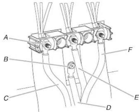
A. 10-32 hex nut
D. Green ground wire
B. Ground-link
E. Neutral (center) wire
F. Line 1 (black)
C. Line 2 (red)
- Connect line 2 (red) and line 1 (black) wires to the outer terminal block posts with 10-32 hex nuts.
- Using a torque wrench, tighten the hex nuts recommended torque of 20 in-lbs (2.3 N-m).
NOTE: For power supply cord replacement, use only a power cord rated at 250 V minimum, 40 A or 50 A that is marked for use with nominal 3/8 (3.5 cm) diameter connection opening, with ring terminals and marked for use with ranges.
- Tighten strain relief screws.
IMPORTANT: Verify the tightness of the hex nuts. - Replace terminal block access cover.
3-Wire Connection: Power Supply Cord
Use this method only if local codes permit connecting chassis ground conductor to neutral wire of power supply cord.
- Feed the power supply cord through the strain relief in the cord/conduit plate on bottom of range. Allow enough slack to easily attach the wiring to the terminal block.
A. Terminal block
C. UL listed strain relief
B. Ground-link
D. Power supply cord
wires-large opening
- Use 3/8'' (9.5 mm) nut driver to connect the neutral (white) wire to the center terminal block post with one of the 10-32 hex nuts.
A. 10-32 hex nut
D. Neutral (white) wire
B. Line 2 (red)
E. Line 1 (black)
C. Ground-link screw
- Connect line 2 (red) and line 1 (black) wires to the outer terminal block posts with 10-32 hex nuts.
- Using a torque wrench, tighten the hex nuts to a recommended torque of 20 in-lbs (2.3 N-m).
NOTE: For power supply cord replacement, only use a power cord rated at 250 V minimum, 40 A or 50 A that is marked for use with nominal 3 / 8 (3.5 cm) diameter connection opening, with ring terminals and marked for use with ranges.
- Tighten strain relief screws.
IMPORTANT: Verify the tightness of the hex nuts.
- Replace terminal block access cover.
Direct Wire
AWARNING

Electrical Shock Hazard
Disconnect power before servicing.
Use 8 gauge copper or 6 gauge aluminum wire.
Electrically ground range.
Failure to follow these instructions can result in death, fire, or electrical shock.
Direct Wire Installation: Copper or Aluminum Wire
This range may be connected directly to the fuse disconnect or circuit breaker box. Depending on your electrical supply, make the required 3-wire or 4-wire connection.
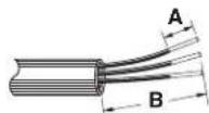
- Strip outer covering back 3^ (7.6 cm) to expose wires. Strip the insulation back 1^ (2.5 cm) from the end of each wire.
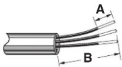
A. 3 / 8'' (1 cm)
B. 3'' (7.6 cm)
- Allow enough slack in the wire to easily attach the wiring terminal block.
- Complete electrical connection according to your type of electrical supply.
4-wire (recommended)
3-wire (if 4-wire is not available)
4-Wire Connection: Direct Wire
Use this method for:
New branch-circuit installations (1996 NEC)
Mobile homes
Recreational vehicles
In an area where local codes prohibit grounding through the neutral
- Part of metal ground strap must be cut out and removed.
A. Metal ground strap
B. Ground-link screw
- Use a Phillips screwdriver to remove the ground-link screw from the back of the range. Save the ground-link screw and the end of the ground link under the screw.
- Pull the wires through the strain relief on bottom of range. Allow enough slack to easily attach wiring to the terminal block.
A. Terminal block
B. Ground-link screw
C. Cord/conduit plate
D. Bare (green) ground wire
E. Line 2 (red) wire
F. Neutral (white) wire
G. Line 1 (black) wire
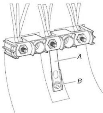
- Attach terminal lugs to line 1 (black), neutral (white), and line 2 (red) wires. Loosen (do not remove) the setscrew on the front of the terminal lug and insert exposed wire end through bottom of terminal lugs. Securely tighten setscrew to torque as shown in the following Bare Wire Torque Specifications chart.
A. Terminal lug
D. Neutral (white) wire
B. Setscrew
E. Line 1 (black) wire
C. Line 2 (red) wire
Bare Wire Torque Specifications
Attaching terminal lugs to the terminal block - 20 lbs-in (2.3 N-m)
Wire Awg Torque
8 gauge copper 25 lbs-in (2.8 N-m)
6 gauge aluminum 35 lbs-in (4.0 N-m)
- Use a hex or Phillips screwdriver to connect the bare (green) ground wire to the range with the ground-link screw and ground-link section. The ground wire must be attached first and must not contact any other terminal.
- Use 3/8 nut driver to connect the neutral (white) wire to the center terminal block post with one of the 10-32 hex nuts.
A. 10-32 hex nut
B. Line 2 (red)
C. Bare (green) ground wire
D. Ground-link screw
E. Neutral (white) wire
F. Line 1 (black)
G. Terminal lug
- Connect line 2 (red) and line 1 (black) wires to the outer terminal block posts with 10-32 hex nuts.
- Using a torque wrench, tighten the hex nuts to a recommended torque of 20 in-lbs (2.3 N-m).
- Securely tighten hex nuts.
IMPORTANT: Verify the tightness of the hex nuts.
- Replace terminal block access cover.
3-Wire Connection: Direct Wire
Use this method only if local codes permit connecting ground conductor to neutral supply wire.
- Pull the wires through the conduit on cord/conduit plate on bottom of range. Allow enough slack to easily attach the wiring to the terminal block.
A. Terminal block
D. Line 2 (red) wire
B. Ground-link
E. Bare (green) ground wire
screw
F. Line 1 (black) wire
C. Cord/conduit
plate
- Attach terminal lugs to line 2 (red), bare (green) ground, and line 1 (black) wires. Loosen (do not remove) the setscrew on the front of the terminal lug and insert exposed wire end 1. Pull the through bottom of terminal lugs. Securely tighten setscrew to torque as shown in the following Bare Wire Torque Specifications chart.
A. Terminal lug
D. Bare (green) ground wire
B. Setscrew
E. Line 1 (black) wire
C. Line 2 (red) wire
Bare Wire Torque Specifications
Attaching terminal lugs to the terminal block - 20 lbs-in (2.3 N-m).
Wire Awg Torque
8 gauge copper 25 lbs-in (2.8 N-m)
6 gauge aluminum 35 lbs-in (4.0 N-m)
- Use 3/8 nut driver to connect the bare (green) ground wire to the center terminal block post with one of the 10-32 hex nuts.
A. 10-32 hex nut
D. Bare (green) ground wire
B. Line 2 (red)
E. Line 1 (black)
C. Ground-link
F. Terminal lug
-
Connect line 2 (red) and line 1 (black) wires to the outer terminal block posts with 10-32 hex nuts.
-
Using a torque wrench, tighten the hex nuts to a recommended torque of 20 in-lbs (2.3 N-m).
- Securely tighten hex nuts.
IMPORTANT: Verify the tightness of the hex nuts.
- Replace terminal block access cover.
Storage Printer
The storage drawer can be removed. Before removing, make sure drawer is cool and empty.
To Remove:
- Pull the storage drawer straight back to the drawer stop.
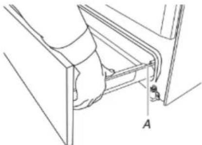
A. Drawer stop notch
- Lift up the front of the drawer and pull the drawer out.
To Replace:
- Lift up the front of the drawer and place the rear of the drawer inside the range so that the drawer stop notch is behind the drawer glide.
-
Lower the drawer so that the edge of the slide rail drops into the slot in the drawer glide.
-
Slowly push the drawer into the range.
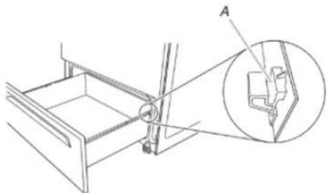
A. Engage drawer glide.
NOTE: When properly installed, the rear slides on the bottom of the drawer will engage the base rails and the drawer will not tip when items are placed in the drawer. 2. O
Oven Door
For normal range use, it is not suggested to remove the oven door. However, if removal is necessary, make sure the oven is off and cool. Then, follow these instructions. The oven door is heavy
To Remove:
- Open oven door all the way.
- Pinch the hinge latch between two fingers and pull forward. Repeat on other side of oven door.
A. Hinge latch
- Close the oven door as far as it will shut.
- Lift the oven door while holding both sides.
Continue to push the oven door closed and pull it away from the oven door frame.
To Replace:
- Insert both hanger arms into the door. Be sure that the hinge notches are engaged in the oven door frame.

A. Hinge notch
- Open the oven door.
The door should be able to open all the way.
3. Move the hinge levers back to the locked position. Check that the door is free to open and close and is level while closed. If is not, repeat the removal and installation procedures.
Complete Installation
- Check that all parts are now installed. If there is an extra part, go back through the steps to see which step was skipped.
- Check that you have all of your tools.
- Check that you have all of the range accessories, especially oven racks. These accessories may be in the range packaging.
- Dispos of/recycle all packaging materials.
- Check that the range is level. See the "Level Range" section.
- Use a mild solution of liquid household cleaner and warm water to remove waxy residue caused by shipping material. Dry thoroughly with a soft cloth. For more information, see the "Range Maintenance and Care" section.
- Read the Quick Start Guide and online Control Guide.
- Plug power cord into appropriate outlet. Turn power on.
- Turn on surface burners and oven. See the Quick Start Guide and online Control Guide for specific instructions on range operation.
NOTE: Odors and smoke are normal when the oven is used the first few times.
If Range Does Not Operate, Check the Following:
Household fuse is intact and tight; or circuit breaker has not tripped.
- Range is plugged into a grounded outlet.
Electrical supply is connected.
IMPORTANT: If the range control displays an "F9" or "F9, E0" error code, the electrical outlet in the home may be miswired. Disconnect power and contact a qualified electrician to verify the electrical supply.
- When the range has been on for 5 minutes, check for heat. If the range is cold, turn off the range and contact a qualified electrician.
If You Need Assistance or Service:
Please reference the Quick Start Guide for contact information.
Moving the Range
AWARNING

Tip Over Hazard
A child or adult can tip the range and be killed.
Install anti-tip bracket to floor or wall per installation instructions.
Slide range back so rear range foot is engaged in the slot of the anti-tip bracket.
Re-engage anti-tip bracket if range is moved.
Do not operate range without anti-tip bracket installed and engaged.
Failure to follow these instructions can result in death, serious burns to children and adults.
When moving range, slide range onto cardboard or hardboard to avoid damaging the floor covering.
If removing the range is necessary for cleaning or maintenance:
For power supply cord-connected ranges:
- Slide range forward.
- Unplug the power supply cord.
- Complete cleaning or maintenance.
- Plug in power supply cord.
- Check that the anti-tip bracket is installed and engaged. See the "Verify Anti-Tip Bracket Is Installed and Engaged" section.
- Check that range is level.
For direct-wired ranges:
WARNING

Electrical Shock Hazard
Disconnect power before servicing.
Replace all parts and panels before operating.
Failure to do so can result in death or electrical shock.
- Disconnect power.
- Slide range forward.
- Complete cleaning or maintenance.
- Check that the anti-tip bracket is installed and engaged. See the "Verify Anti-Tip Bracket Is Installed and Engaged" section.
- Check that range is level.
or 6. Reconnect power.
SECURITE DE LA CUISINIÈRE
National Fire Protection Association
1 BatteryMarch Park
Quincy, MA 02169-7471
Canadian Standards Association
178 Rexdale Blvd.
Toronto, ON M9W 1R3 CANADA
National Fire Protection Association
1 BatteryMarch Park
Quincy, MA 02169-7471
Canadian Standards Association
178 Rexdale Blvd.
Toronto, ON M9W 1R3 CANADA
16,6-22,5kW12,6-18,5kW 50^**
Aluminio, calibre 6 35 Ib-in (4,0 Nm)