
AIROS 650S - Electrical cabinet Mirka - Free user manual and instructions
Find the device manual for free AIROS 650S Mirka in PDF.

| Product type | Electrical cabinet for motor drive |
| Brand | Mirka |
| Model | AIROS 650S |
| Cabinet dimensions | 380 x 300 x 210 mm (W x H x D) |
| Motor drive dimensions | 72 x 30 x 200 mm (W x H x D) |
| DIN rail dimensions | 95 x 55 x 210 mm (W x H x D) |
| Input supply | 48 VDC, range 46-50 VDC, 10 A max |
| Rated power | 350 W |
| Speed range | 1000-10000 rpm |
| Protection | Overcurrent, overtemperature, undervoltage, overvoltage |
| Interfaces | Modbus RTU (RS-485), Profinet I/O, EtherNet/IP (via gateway), 4-bit digital inputs |
| Relay output | Single-pole, NO, 250 VAC/125 VDC, 10 A |
| Ambient temperature | 0 – 40 °C |
| Humidity | ≤ 95% RH, non-corrosive |
| IP rating | IP40 |
| Warranty | 1 year |
| Main functions | Speed control, self-test, reset, tool change on the fly |
| Compliance | CE, directives 2014/35/EU, 2014/30/EU, 2011/65/EU |
| Standards | EN 61439-1, EN 61439-2, EN 61800-3, EN IEC 63000 |
| Maintenance and cleaning | Check cables, clean with dry cloth, no specific maintenance |
| Safety | Installation by qualified electrician, disconnect power before intervention, antistatic wrist strap |
| Spare parts and repairability | Motor drive, sanding unit, polishing unit, power supply, communication gateway (covered by warranty). Repair by Mirka or authorized services. |
| Storage temperature | -20 – 80 °C |
Frequently Asked Questions - AIROS 650S Mirka
User questions about AIROS 650S Mirka
0 question about this device. Answer the ones you know or ask your own.
Ask a new question about this device
Download the instructions for your Electrical cabinet in PDF format for free! Find your manual AIROS 650S - Mirka and take your electronic device back in hand. On this page are published all the documents necessary for the use of your device. AIROS 650S by Mirka.
USER MANUAL AIROS 650S Mirka
Mirka ^® MotorDriveCabinet
Electricalmanual

natural_image
Stylized illustration of a bulldog in aggressive posture (no text or symbols)Mirka® MotorDrive Cabinet
de Bedienungsanleitung....4 Operating instructions (original)....23en Instrucciones de manejo....41es
Operating instructions....143UK|en
Parts list – spareparts
| DescriptionMirka code | |
| Power supply 48 VMIA6513211 | |
| Power supply 24 VMIA6513411 | |
| Profinet GatewayMIA6513311 | |
| EtherNet/IP gatewayMIA6514011 | |
| MODBUS RTU Gateway CableMIA6513312 | |
| Motor driveMIA6513112 | |
| Shielded cable for tool (10m)MIA6512311 | |
Halteregister (F3, F6, F16)
natural_image
Symbol of a trash bin with crossed lines indicating no waste or restriction, and a solid black rectangle below (no text or labels)Declaration of conformity
Mirka Ltd, 66850 Jeppo, Finland
declare under our sole responsibility that the Mirka® products (listed below and see "Technical data" table for particular model) to which this declaration relates are in conformity with the following standards or other normative documents: EN 61439-1:2011, EN 61439-2:2011, EN 61800-3:2004+A1:2012, EN IEC 63000:2018 in accordance with the regulations 2014/35/EU, 2014/30/EU, 2011/65/EU.
Products: Mirka ^® Motor Drive Cabinet
Jeppo 19.02.2025
Place and date of issue


Manufacturer /Supplier
Mirka Ltd
66850 Jeppo, Finland
Tel. +358 20 760 2111
Fax +358 20 760 2290
www.mirka.comStefan Sjö

Original instructions. We reserve the right to make changes to this manual without prior notice.
Warranty
Mirka warrants that your components are free from manufacturing and material defects.
Mirka components have a 1-year warranty starting from the date of purchase. Only manufacturing and material defects are covered by the warranty.
If a problem occurs caused by a manufacturing defect material or by workmanship, Mirka will repair your component free of charge in accordance with the warranty terms and conditions stated herein. To keep your component warranty valid the component must be used, maintained and operated in compliance with the operating instructions.
Terms and conditions
Mirka's component warranty covers defects in material and workmanship.
Components covered by the warranty:
•motor drive
•sanding unit
- polishing unit
•power supply
- communication gateway
Warranty does not cover:
- any damage caused or resulting from transport, receipt of delivery, installation, commissioning, misuse, neglect in usage or maintenance, accidents, exposure to extreme unacceptable ambient temperature, acids, water, unsuitable storage, excessive impact, or operation outside the rated specifications.
• defects caused by spare parts, accessories or components other than Mirka original spare parts or accessories. - normal wear and tear items such as: backing pad, break seal, exhaust fitting, bearings, rubber mount, signal cable or power cable.
- components that have been: modified, repaired or repair attempts (by other than Mirka authorized service), partly or completely disassembled components.
No other than Mirka have the authority to change, extend or add to given warranty terms and conditions.
The manufacturer cannot be hold responsible for consequential damages compensations for downtime, production loss, injuries or property damages.
A warranty claim must be submitted with as short delay as possible. A warranty claim must be submitted within the warranty period.
Symbols
| CE | Complies with EU relevant standards |
 | Warning: Electricity |
Installation overview
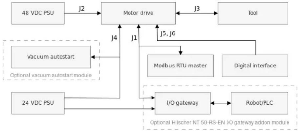
flowchart
graph TD
    A["48 VDC PSU"] -->|J2| B["Motor drive"]
    B -->|J3| C["Tool"]
    D["24 VDC PSU"] -->|J4| B
    E["Vacuum autostart"] -->|J1| B
    F["Modbus RTU master"] -->|J5, J6| B
    G["Digital interface"] --> B
    H["I/O gateway"] -->|J1| B
    I["Robot/PLC"] -->|J5, J6| B
    J["Optional vacuum autostart module"] -->|J4| B
    K["Optional Hilischer NT 50-RS-EN I/O gateway addon module"] -->|J1| B
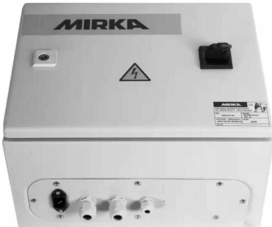
General
- Connect the 48 VDC power supply to the motor drive (J2 connector).
- Connect the tool to the motor drive (J3 connector).
NOTE! It is not recommended to use a shielded cable for tool that is longer than 10m.
Modbus RTU interface
- Use the J1 connector to connect the motor drive to the Modbus RTU bus.
I/O gateway to Modbus RTU interface
- Connect the 24 VDC power supply to the gateway and connect the DSUB-9 adapter cable between the gateway (X2 connector) and the motor drive (J1 connector).
Digital control interface
- Use the J6 connector to connect the common GND between the systems.
- Use the J5 connector to select the operation using the four digital input signals.
Relay interface
• The N/O relay pins are available on the J4 connector.
Technical data for motor drive
| Input | |
| Nominal input voltage | 48 VDC |
| Input voltage range | 46 - 50 VDC |
| 10 AMaximum input current | |
| 350 WRated power | |
| Speed control | |
| Speed range | 1000 - 10000 rpm |
| Protection | |
| YesOverload protection | |
| YesOverheat protection | |
| Interfaces | |
| Input interfaces | Modbus RTU (RS-485)Profinet I/O (gateway module)EtherNet/IP (gateway module)4-bit digital inputs (15-33 VDC) |
| Output interfaces | Single pole, non-latching N/O relay, 250 VAC/ 125 VDC, 10 A |
| Environmental | |
| Ambient temperature | 0 - 40 °C |
| Humidity | Maximum 95% RH, non-corrosive, no dripping water |
| Storage temperature | -20 to 80 °C |
| IP40IP Class | |
| Dimensions | |
| Motor drive cabinet | 380 x 300 x 210 mm (W x H x D) |
| Motor drive | 72 x 30 x 200 mm (W x H x D) |
| Motor drive mounted in DIN -rail holder | 95 x 55 x 210 mm (W x H x D) |
Safety instructions

Electrical installation must be carried out by a competent electrician!

The motor drive has been designed for fixed installations only.

Do not perform any voltage withstand tests on any part of the motor drive or the tool. Product safety has been fully tested at the factory.

Ground yourself with an anti-static wristband before touching the motor drive (setting jumpers and similar actions) to avoid electrostatic voltage discharge damage to the motor drive.

Always disconnect the power before performing any work on the cabinet.
Warnings

Make sure that all the AC-DC power supplies are properly earthed and that the motor drive cannot come in contact with live mains voltage.

An external emergency stop circuit is recommended.
Before running the tool

Before starting the tool, check that the tool is mounted properly and ensure that the motor drive is installed properly.
Motor drive overview
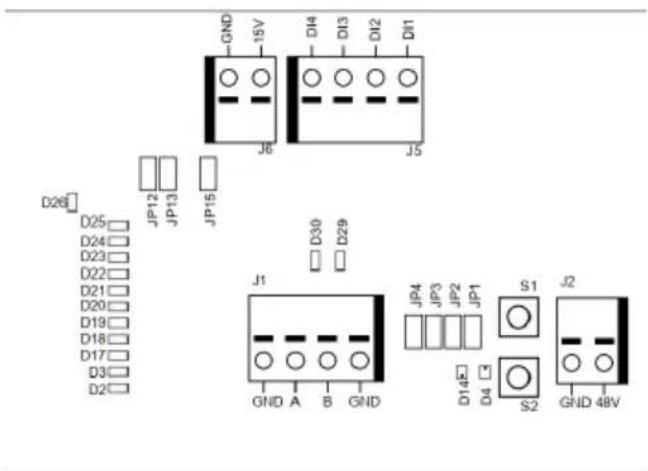
Motor drive PCB connectors, buttons, jumpers, indicators, mounting holes and dimensions
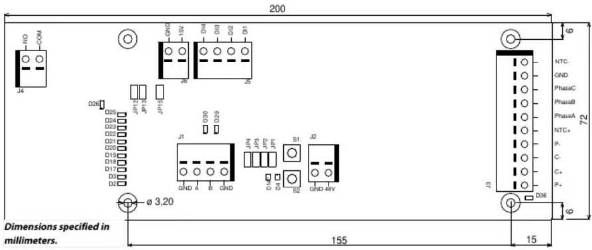
The motor drive PCB comes mounted in a DIN-rail holder that can be attached to a standard 35 x 7.5mm EN50022 DIN-rail, but the motor drive PCB can be removed from this holder and mounted using the mounting holes instead. If the mounting holes are used, then it is recommended to use 20 mm metal standoffs and 10 mm M3 screws when mounting the motor drive PCB.
It is recommended to use 10 mm ferrules with plastic sleeve for each wire that is attached to any of the connectors. The wires can then easily be pushed into the connectors and released with the help of a small flat-head screwdriver (3.5 mm blade width, 0.6 mm blade thickness).
Connector description
| DescriptionPINConnector | ||
| GNDGNDJ1 | ||
| Modbus RTU RS-485 (A)AJ1 | ||
| Modbus RTU RS-485 (B)BJ1 | ||
| GNDGNDJ1 | ||
| DescriptionPINConnector | ||
| GNDGNDJ2 | ||
| 48 VDC input48VJ2 | ||
| Motor cable colorPINConnector | ||
| WhiteP+J3 | ||
| PinkC+J3 | ||
| GreyC-J3 | ||
| GreenP-J3 | ||
| Brown, (0,25mm2)NTC+J3 | ||
| Brown, (0,25mm2)Phase AJ3 | ||
| J3 | BluePhase B | |
| Phase CJ3 | Black | |
| J3 | GND | Cabinet earth |
| J3 | NTC- | Yellow |
| Shield | Connected to ground, X2 in Mirka cabinet | |
| DescriptionPINConnector | ||
| J4 | COM | Relay COM |
| J4 | NO | Relay NO |
| DescriptionPINConnector | ||
| J5 | DI1 | Digital speed control input bit 1 |
| J5 | DI2 | Digital speed control input bit 2 |
| J5 | DI3 | Digital speed control input bit 3 |
| J5 | DI4 | Digital speed control input bit 4 |
| DescriptionPINConnector | ||
| 15VJ6 | 15 VDC output | |
| J6 | GNDGND | |
Button description
| Button | Description |
| S1 | Self-test button |
| S2 | Reset button |
Indicator description
| Indicator | Description |
| D2 | Speed set-point indicator, lit if speed set-point 1 active. Modbus RTU slave address indicator, bit 1. |
| D3 | Speed set-point indicator, lit if speed set-point 3 active. Modbus RTU slave address indicator, bit 2. |
| D4 | Tool status indicator. Lit red when the tool is stopped, lit green when the tool is running. |
| D14 | Motor drive state indicator. Lit green when motor drive is in ON-state. Blinking green when motor drive is in OFF-state. |
| D17 | Speed set-point indicator, lit if speed set-point 5 active. Modbus RTU slave address indicator, bit 3. |
| D18 | Speed set-point indicator, lit if speed set-point 7 active. Modbus RTU slave address indicator, bit 4.DescriptionIndicator |
| D19 | Speed set-point indicator, lit if speed set-point 9 active. Modbus RTU slave address indicator, bit 5. |
| D20 | Speed set-point indicator, lit if speed set-point 11 active. Modbus RTU slave address indicator, bit 6. |
| D21 | Speed set-point indicator, lit if speed set-point 13 active. Modbus RTU slave address indicator, bit 7. |
| D22 | Modbus RTU slave address indicator, bit 8. |
| D23 | Lit if D2–D3, D17–D22 indicator mode is Modbus RTU slave address. |
| D24 | Lit if digital speed control interface is enabled. |
| D25 | Lit if the alarm status flag is set. |
| Relay status indicator.D26 | |
| D29 | Modbus RTU receive indicator. |
| D30 | Modbus RTU transmit indicator. |
| D36 | Possible tool wiring fault. Turns red when a possible fault in tool C+/C-/P+/P- wiring is detected. |
Speed set-point display
| Tool | Min speed (RPM) | Max speed (RPM) | ||||||||||||||
| AIROS 550 CV/NV | 100004000AIROS 650 CV/NV | |||||||||||||||
| AIROS 350 CV/NV | ||||||||||||||||
| AIROS 150 NV | 80004000AIROP 312 NV | |||||||||||||||
| AIOS 130 NV | ||||||||||||||||
| 100005000AIOS 353 CV/NV | ||||||||||||||||
| 30001000AIRP 300 | ||||||||||||||||
| Speed set | Bit map | Speed at various setpoints (RPM) | Speed LED:s active | |||||||||||||
| DI4 | DI3 | DI2 | DI1 | Tool RPM | Tool RPM | Tool RPM | Tool RPM | Tool RPM | D2 | D3 | D17 | D18 | D19 | D20 | D21 | |
| 4000-10000 | 4000-8000 | 5000-10000 | 1000-3000 | |||||||||||||
| 1 | 0 | 0 | 0 | 1 | 4000 | 4000 | 5000 | 1000 | X | |||||||
| 2 | 0 | 0 | 1 | 0 | 4500 | 4333 | 5417 | 1167 | X | |||||||
| 3 | 0 | 0 | 1 | 1 | 5000 | 4666 | 5834 | 1334 | X | X | ||||||
| 4 | 0 | 1 | 0 | 0 | 5500 | 4999 | 6251 | 1501 | X | X | ||||||
| 5 | 0 | 1 | 0 | 1 | 6000 | 5332 | 6668 | 1668 | X | X | X | |||||
| 6 | 0 | 1 | 1 | 0 | 6500 | 5665 | 7085 | 1835 | X | X | X | |||||
| 7 | 0 | 1 | 1 | 1 | 7000 | 5998 | 7502 | 2002 | X | X | X | X | ||||
| 8 | 1 | 0 | 0 | 0 | 7500 | 6331 | 7919 | 2169 | X | X | X | X | ||||
| 9 | 1 | 0 | 0 | 1 | 8000 | 6664 | 8336 | 2336 | X | X | X | X | X | |||
| 10 | 1 | 0 | 1 | 0 | 8500 | 6997 | 8753 | 2503 | X | X | X | X | X | |||
| 11 | 1 | 0 | 1 | 1 | 9000 | 7330 | 9170 | 2670 | X | X | X | X | X | X | ||
| 12 | 1 | 1 | 0 | 0 | 9500 | 7663 | 9587 | 2837 | X | X | X | X | X | X | ||
| 13 | 1 | 1 | 0 | 1 | 10000 | 8000 | 10000 | 3000 | X | X | X | X | X | X | X | X |
| Bit map | Operation | |||||||||||||||
| DI4 | DI3 | DI2 | DI1 | |||||||||||||
| 0 | 0 | 0 | 0 | Stopped | ||||||||||||
| Run, no speed change0111 | ||||||||||||||||
| Run, no speed change1111 | ||||||||||||||||
Modbus RTU slave address display
| BIT 8 | BIT 7 | BIT 6 | BIT 5 | BIT 4 | BIT 3 | BIT 2 | BIT 1 |
| D2D3D17D18D19D20D21 |
Jumper description
| DescriptionDefaultJumpers | ||
| JP1 | Not set | Reserved for future use |
| Not setJP2 | If set, a terminating resistor of 270 Ωis connected across Modbus RTU pins A and B. | |
| Not setJP3 | If set, a pull-down resistor of 10 kΩ is connected to Modbus RTU B-pin. | |
| Not setJP4 | If set, a pull-up resistor of 10 kΩ is connected to Modbus RTU A-pin. | |
| JP12 | Not set | If set, digital speed control feature is enabled. |
| Not setJP13 | If set, D2-D3, D17-D22 indicators will output the current Modbus RTU slave address instead of speed set-point. | |
| JP15 | Not set | Reset to factory settings. |
Tool cable connector pinout
| DescriptionPin (colour, size) | |
| PE (green-yellow, 1.0 mm2) | Not in use |
| Phase A1 (brown, 1.00 mm ) | |
| 2 (blue, 1.00 mm ) | Phase B |
| 3 (black, 1.00 mm ) | Phase C |
| A (grey, 0.25 mm ) | C- |
| B (pink, 0.25 mm ) | C+ |
| C (green, 0.25 mm ) | P- |
| C (yellow, 0.25 mm ) | NTC- |
| D (brown, 0.25 mm ) | NTC+ |
| E (white, 0.25 mm ) | P+ |
NOTE! NTC- and P- are connected together to the same PIN inside the connector.
Hilscher NT 50-RS-EN adapter cable pinout (female DSUB-9)
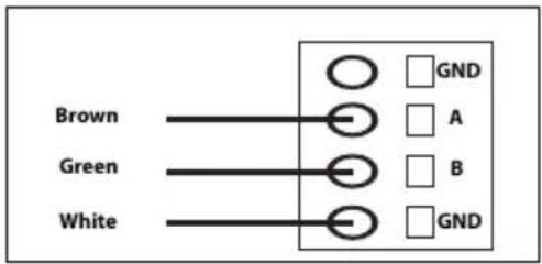
| DescriptionPIN (colour) | |
| GND1 (white, WH) | |
| 4 (brown, BN) | Modbus RTU (A, RxD / TxD+) |
| 5 (green, GN) | Modbus RTU (B, RxD / TxD-) |
| ShieldSHIELD |
Terminal block connections (Firmware v. 3.05 and newer)
Enable-State:
For the sander to be able to operate, terminal block 4 must be connected to a 24V output from the robot/PLC, while terminal block 6 should be connected to 0V on the robot/PLC.
For enhanced safety, the Enable-State output could be set to low if the robot encounters an issue that causes it to stop. This will automatically halt the sanding/polishing head.
The 3 meter, 2-pole cable provided with the cabinet should be used for connecting the enable-state as per the instructions
Vacuum Autostart Module:
Customers can integrate the optional Mirka AutoStart Module (MIA6519011) to enable automatic start/stop functionality for the dust extractor. To do this, connect terminal block 5 to the positive (+) terminal on the AutoStart Module and terminal block 7 to the negative (−) terminal.
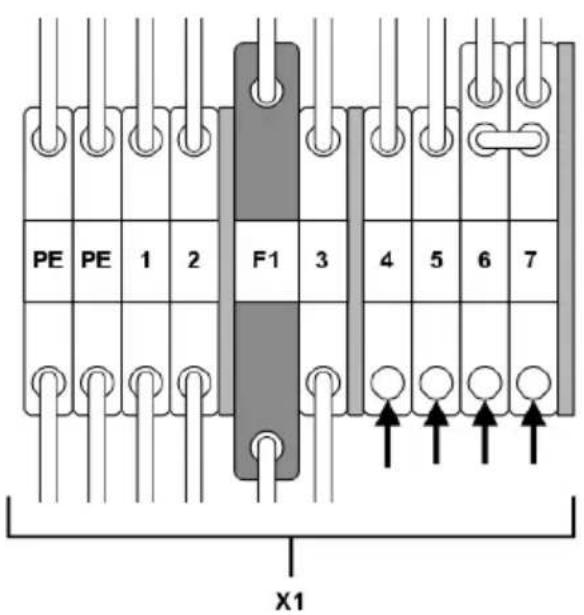
| Terminal blockFunction/Connection | |
| Enable-state robot/PLC output 24V | X1:4 (connected to pin J5, DI1) |
| X1:6Robot/PLC 0V | |
| Autostart module + | X1:5 (connected to pin J4, NO) |
| X1:7Autostart module - |
Modbus RTU
Modbus RTU over RS-485 is used to communicate with the motor drive. The motor drive is configured as a Modbus RTU slave device and the default slave address is 86. The slave address can be changed if it conflicts with another Modbus RTU slave device.
The J1 connector on the motor drive is used for Modbus RTU communication. A shielded twisted pair cable is recommended and the shield should be earthed only at one point, normally at the master device. The A-pin of the J1 connector is equivalent to RxD / TxD+ and the B-pin is equivalent to RxD / TxD−.
RS-485 configuration
| 19200BAUD RATE | |
| EVENPARITY | |
| 1STOP BITS | |
| 8DATA BITS |
Coil registers (F1, F5, F15)
| DesciptionNameData typeAddre | |||
| 00001 - 00012 | Uint16 | Digital outputs | Coils 1–11 are reserved for future use.Coil 12 is the relay located on the motor drive. |
Input registers (F4)
NOTE! Input registers 30001-30016 are drive specific. As an example: "Drop RPM count" refers to the total number of "Drop RPM count" for all tools that have been connected to the motor drive.
NOTE! * Requires firmware version 3.05 or newer and tool firmware 0.05 or newer.
| DescriptionNameData typeAdre | |||
| Drop RPM countUint1630001 | The number of times the speed has dropped from set-point by more than 25%. | ||
| Warm tool countUint1630002 | The number of times the tool temperature has exceeded the “warm”limit, 79°C. | ||
| 30003 | Uint16 | Warm motor drive count | The number of times the motor drive temperature has exceeded the “warm”limit, 73°C. |
| Hot tool countUint1630004 | The number of times the tool temperature has exceeded the “hot”limit, 134°C. | ||
| 30005 | Uint16 | Hot motor drive count | The number of times the motor drive temperature has exceeded the “hot”limit, 117°C. |
| 30006 | Uint16 | Stop tool count | The number of times the tool temperature has exceeded the “stop”limit, 142°C. |
| 30007 | Uint16 | Stop motor drive count | The number of times the motor drive temperature has exceeded the “stop”limit, 123°C. |
| 30008 | Uint16 | Voltage out of range count | The number of times the input voltage has not been within 44 to 52 VDC. |
| Over-current low countUint163000 | The number of times the current has exceeded 15.1 A. | ||
| 30010 | Uint16 | Over-current medium countUsage count longUint1630011 | The number of times the current has exceeded 18.2 A.The number of times the run time has been more than 60 seconds. |
| Usage count mediumUint1630012 | The number of times the run time has been between 20 and 60 seconds. | ||
| Usage count shortUint1630013 | The number of times the run time has been less than 20 seconds. | ||
| 30014 | Uint16 | Usage time hours | Hours part of usage time. |
| 30015 | Uint16 | Usage time minutes | Minutes part of usage time. |
| 30016 | Uint16 | Usage time seconds | Seconds part of usage time. |
| Current in mA.CurrentInt1630017 | |||
| 30018 | Uint16 | Speed | Speed in RPM. |
| 30019 | Uint16 | Tool temperature | Tool temperature in °C. |
| 30020 | Uint16 | Motor drive temperature | Motor drive temperature in °C. |
| 30021-30030 | Char[20] | Firmware version | Firmware version and build date, e.g. “2.0 Jan 18 14:00”. |
| 30031-30039 | Char[18] | Part version | Part version and motor drive identification number, e.g. “AI1.3 123456” |
| 30040-30046 | Char[14] | Motor drive serial number | Motor drive serial number, e.g. “749474379001” |
| 30047 | Uint16 | Alarm status flagTool IDUint1630061 | Alarm status flag can at any given time hold a combination of values from the list below. Check the individual bits to determine the type of alarms that are currently triggered. This flag is automatically cleared after 5 seconds ifthecause of the alarm trigger is no longer present. 0x0000 = Not triggered 0x0001 = Tool overheated 0x0002 = Motor drive overheated 0x0004 = Over-current 0x0008 = Under-voltage 0x0010 = Over-voltage 0x0020 = Self-test running 0x0040 = RPM drop 0x0080 = High current 0x0100 = Tool change in progress 0x0200 = Possible toolwiringfault 0x0400 = Factory reset mode 0x0800 = Write protection dis-abled 0x1000 = Tool disconnected (communication lost)* |
| Tool min speedUint1630062 | |||
| Tool max speedUint1630063 | |||
| Tool tag availableUint1630064 | |||
| Tool serial numberChar[14]30065-30071 | |||
| Tool pad diameterUint1630174* | |||
| Tool Z offsetUint1630175* | |||
| 30176* | Uint16 | Tool orbit | Tool orbit in mm. |
| Tool weightUint1630177* | |||
| 30178* | Uint16 | Tool CoG | Tool center of gravity |
| 30179* | Uint16 | Tool pad width | |
| 30180* | Uint16 | Tool pad length | |
| 30181-30183* | Char[3] | Tool firmware version | Firmware version e.g. "0.04" |
| Tool model nameChar[10]30181-30193* | |||
Holding registers (F3, F6, F16)
| DescriptionNameData typeAddr | |||
| Char[20]40001-40010 | Device name | Max length 19 printable characters, e.g. "AIMD 749474379001". | |
| Uint1640011 | Speed set-point | Speed set-point, not the actual speed, between min- and max speed of tool. | |
| Uint1640012 | Operation | Motor drive state, can be a combination of the following:0x0001 = RUN0x0002 = STOP*0x0004 = ON*0x0008 = OFF0x0010 = TOOL CHANGE START0x0020 = TOOL CHANGE END0x0040 = WRITE PROTECTION DISABLE0x0080 = WRITE PROTECTION ENABLENOTE! When writing a new state value, the value can only be a single state, not a combination of multiple states, e.g. ON+RUN cannot be written simultaneously. | |
| Uint1640013 | Slave address | Defaults to 86 but can be changed if needed. | |
NOTE! * Not included on firmware 3.05 or later
Profinet I/O or EtherNet/IP gateway (Hilscher NT 50-RS-EN)
If the motor drive needs to be connected as Profinet I/O or EtherNet/IP device, the Hilscher NT 50-RS-EN gateway can be used. The gateway is connected to the motor drive via the DSUB-9 connector on the gateway and the J1 connector on the motor drive. Below is the pinout for the DSUB-9 (X2 connector) found on the gateway:
| DescriptionsSignalPINRS-4 | |||
| 1 | GND | Reference potential,ground of power supply | |
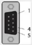 | RxD / TxD+4 | Receive data /Transmit data positive | |
| RxD / TxD-5 | Receive data /Transmit data negative |
A pull-up resistor of 10 kΩ is internally connected in the gateway to "RxD / TxD+".
A pull-down resistor of 10 kΩ is internally connected in the gateway to "RxD / TxD−".
Detailed documentation about the gateway and configuration tools can be downloaded from the Hilscher website: www.hilscher.com
Configuration
The gateway comes pre-configured from Mirka as a Profinet I/O slave device or a EtherNet/IP I/O adapter. The "SYCON.net" software from Hilscher can be used to re-configure the device. The "Ethernet Device Setup" software from Hilscher can be used to change the network configuration. The IP address usually needs to be re-assigned after a configuration change.
Default network configuration for Profinet
| 192.168.2.191IP ADDRESS | |
| 255.255.255.0SUBNET MASK | |
| 0.0.0.0DEFAULT GATEWAY | |
| nt50enpnsDEVICE NAME | |
| 118INPUT SIZE | |
| 102 (Firmware v. 3.05 or newer) | |
| 5OUTPUT SIZE |
Default network configuration for EtherNet/IP
| 192.168.125.110IP ADDRESS | |
| MirkaENIPNAME | |
| 101INPUT ASSEMBLY | |
| 102INPUT SIZE | |
| 100OUTPUT ASSEMBLY | |
| 5OUTPUT SIZE |
Profinet I/O to Modbus RTU signal mapping firmware 3.04 or older
| Name | Modbus register | Data length | Trigger | Profinet I/O | Data length |
| SetRelay | 00012 | 1 coil | Changed data | 1 | 1 byte out |
| SetSpeedRegister | 40011 | 1 register | Changed data | 2 | 1 word out |
| SetOperationRegister | 40012 | 1 register | Changed data | 3 | 1 word out |
| DeviceName | 40001-40010 | 10 registers | Cyclically 10 sec. | 4 | 10 words in |
| CommonInputs | 30017-30020 | 4 registers | Cyclically 1 sec. | 5 | 4 words in |
| MiscInputs | 30001-30016 | 16 registers | Cyclically 5 sec. | 6 | 16 words in |
| AlarmStatus | 30047 | 1 register | Cyclically 1 sec. | 7 | 1 word in |
| 10 registers30021-30030FirmwareVersion sec. | 10 words in8Cyclically 10 | ||||
| PartVersionSerialNumber | 30031-30046 | 16 registers | sec. | 16 words in9Cyclically 10 | |
| GetSpeedRegister | 40011 | 1 register | Cyclically 1 sec. | 10 | 1 word in |
| GetOperationRegister | 40012 | 1 register | Cyclically 1 sec. | 11 | 1 word in |
| ReadCoils | 00001-00012 | 12 coils | Cyclically 1 sec. | 12 | 2 bytes in |
Profinet I/O drive firmware 3.05 or newer
| Data length | Type Clause Type Slo dress | ||||
| Slot 1 | 1 byte out | Digital output (re-lay) | BIT | 1 byte | FC5 11 |
| Slot 2 | 2 byte out | Speed set-point (RPM) | UINT16 | 1 word | FC6 10 |
| Slot 3 | 2 byte out | Operation | BIT | 1 word | FC6 11 |
| Slot 4 | 8 byte in | Motor current (mA) | UINT16 | 1 word | FC4 16 |
| Motor RPM (RPM) | UINT16 | 1 word | FC4 17 | ||
| Motor temp (C°) | UINT16 | 1 word | FC4 18 | ||
| Drive temp (C°) | UINT16 | 1 word | FC4 19 | ||
| Slot 5 | 8 byte in | Drive fw. | CHAR | 6 byte | FC4 20-23 |
| Slot 6 | 2 byte in | AlarmStatus | BIT | 1 word | FC4 46 |
| Slot 7 | 4 byte in | Speed set-point (RPM) | UINT16 | 1 word | FC3 10 |
| Operation | BIT | 1 word | FC3 11 | ||
| Slot 8 | 8 byte in | Tool ID | UINT16 | 1 word | FC4 60 |
| Min speed (RPM) | UINT16 | 1 word | FC4 61 | ||
| Max speed (RPM) | UINT16 | 1 word | FC4 62 | ||
| Tool tag available | BIT | 1 word | FC4 63 | ||
| Slot 9 | 16 byte in | Tool serial # | CHAR | 14 byte | FC4 64-71 |
| Slot 10 | 8 byte in | Pad diameter (mm) | UINT16 | 1 word | FC4 173 |
| Tool Z offset (mm) | UINT16 | 1 word | FC4 174 | ||
| Tool orbit (mm) | UINT16 | 1 word | FC4 175 | ||
| Tool weigth (g) | UINT16 | 1 word | FC4 176 | ||
| Slot 11 | 32 byte in | Tool COG Z offset (mm) | UINT16 | 1 word | FC4 177 |
| Pad Width (mm) | UINT16 | 1 word | FC4 178 | ||
| Pad length (mm) | UINT16 | 1 word | FC4 179 | ||
| Tool fw. | CHAR | 6 byte | FC4 180-182 | ||
| Tool model name | CHAR | 20 byte | FC4 183-192 | ||
| Data length | Data type | Type Type Slo dress | |||
| Slot 12 | 16 byte in | Tool usage hours | UINT16 | 1 word | FC4 99 |
| seconds | FC4 1001 byteUINT8Tool usage | ||||
| minutes | FC4 1001 byteUINT8Tool usage | ||||
| Tool usage short count | UINT32 | 2 word | FC4 101-102 | ||
| Tool usage medium count | UINT32 | 2 word | FC4 103-104 | ||
| Tool usage long count | UINT32 | 2 word | FC4 105-106 | ||
EtherNet/IP drive firmware 3.05 or newer
| Modbus AddressData | ||||
| Output | Digital output (relay) | BIT | 1 byte | FC5 11 |
| Output | Speed set-point (RPM) | UINT16 | 1 word | FC6 10 |
| Output | Operation | BIT | 1 word | FC6 11 |
| Input | 2 word | |||
| Input | Motor current (mA) | UINT16 | 1 word | FC4 16 |
| Input | Motor RPM (RPM) | UINT16 | 1 word | FC4 17 |
| Input | Motor temp (C°) | UINT16 | 1 word | FC4 18 |
| Input | Drive temp (C°) | UINT16 | 1 word | FC4 19 |
| Input | AlarmStatus | BIT | 1 word | FC4 46 |
| Input | Speed set-point (RPM) | UINT16 | 1 word | FC3 10 |
| Input | Operation | BIT | 1 word | FC3 11 |
| Input | Tool ID | UINT16 | 1 word | FC4 60 |
| Input | Min speed (RPM) | UINT16 | 1 word | FC4 61 |
| Input | Max speed (RPM) | UINT16 | 1 word | FC4 62 |
| Input | Tool tag available | BIT | 1 word | FC4 63 |
| Input | Tool serial # | CHAR | 14 byte | FC4 64-71 |
| Input | Pad diameter (mm) | UINT16 | 1 word | FC4 173 |
| Input | Tool Z offset (mm) | UINT16 | 1 word | FC4 174 |
| Input | Tool orbit (mm) | UINT16 | 1 word | FC4 175 |
| Input | Tool weigth (g) | UINT16 | 1 word | FC4 176 |
| Input | Tool COG Z offset (mm) | UINT16 | 1 word | FC4 177 |
| Input | Pad Width (mm) | UINT16 | 1 word | FC4 178 |
| Input | Pad length (mm) | UINT16 | 1 word | FC4 179 |
| Input | Tool firmware | CHAR | 6 byte | FC4 180-182 |
| Input | Tool model name | CHAR | 20 byte | FC4 183-192 |
| Input | Drive firmware | CHAR | 6 byte | FC4 20-23 |
| Input | Tool usage hours | UINT16 | 1 word | FC4 99 |
| Input | Tool usage seconds | UINT16 | 1 byte | FC4 100 |
| Input | Tool usage minutes | UINT16 | 1 byte | FC4 100 |
| Input | Tool usage short count | UINT32 | 2 word | FC4 101-102 |
| Input | Tool usage medium count | UINT32 | 2 word | FC4 103-104 |
| Input | Tool usage long count | UINT32 | 2 word | FC4 105-106 |
Siemens TIA Portal V14 gateway mapping example 3.04 or older
Below is a screenshot from TIA Portal V14 showing how the gateway can be mapped into the system. The GSDML file can be found in the Gateway solution DVD downloadable from hilscher.com to add support for the Hilscher NT 50-RS-EN gateway into your system.
| Device overview | ||||||||||
| ... | Module | Rack | Slot | I address | Q address | Type | Article no. | Firmware | ||
| nt50enpns | 0 | 0 | NT 50-EN/PNS | 3.4 x | ||||||
| PNHO | 0 | 0 X1 | nt50enpns | |||||||
| SetRelay | 0 | 1 | 63 | 1 Byte Output | ||||||
| SetSpeedRegister | 0 | 2 | 64...65 | 2 Byte Output | ||||||
| SetOperationRegister | 0 | 3 | 66...67 | 2 Byte Output | ||||||
| DeviceName | 0 | 4 | 68...87 | 20 Byte Input | ||||||
| CommonInputs | 0 | 5 | 88...95 | 8 Byte Input | ||||||
| MiscInputs | 0 | 6 | 96...127 | 32 Byte Input | ||||||
| AlarmStatus | 0 | 7 | 128...129 | 2 Byte Input | ||||||
| FirmwareVersion | 0 | 8 | 130...149 | 20 Byte Input | ||||||
| PartVersion | 0 | 9 | 150...169 | 20 Byte Input | ||||||
| SerialNumber | 0 | 10 | 170...181 | 12 Byte Input | ||||||
| GetSpeedRegister | 0 | 11 | 182...183 | 2 Byte Input | ||||||
| GetOperationRegister | 0 | 12 | 184...185 | 2 Byte Input | ||||||
| ReadCoils | 0 | 13 | 186...187 | 2 Byte Input | ||||||
Basic operation for Modbus RTU
The motor drive must be enabled before the tool can be started. The first operation that should be done is to set the motor drive to the Enabled-state. This operation differs starting from firmware version 3.05. On earlier versions a "Drive enabled" command should be sent to the motor drive, while newer versions have the digital pin DI1 allocated as the Enabled-state. It is not mandatory to send the Disabled-state command before removing power from the motor drive.
When the motor drive is enabled the speed set-point value can be written and the state can be set to RUN-state by sending the RUN-state command. This will cause the tool to run at the set-point speed. To stop the tool, set the motor drive to STOP-state by sending the STOP-state command.
It is recommended to continuously monitor the average speed, average current, tool temperature, motor drive temperature and the alarm status flag. This will help to detect if there are any issues present during operation.
Example sequence for starting and stopping the tool (Firmware v. 3.04 and older):
- Write 4 (0x0004) to the "Operation" register, this will set the motor drive to Enabled-state.
- Write 4000 (0x0FA0) to the "Speed set-point" register, this will set the set-point speed to 4,000 rpm.
- Write 1 (0x0001) to the "Operation" register, this will set the motor drive to RUN-state and the tool will start running.
- Write 2 (0x0002) to the "Operation" register, this will set the motor drive to STOP-state and the tool will stop running.
- Write 8 (0x0008) to the "Operation" register, this will set the motor drive to Disabled-state.
Example sequence for starting and stopping the tool (Firmware v. 3.05 and newer)*:
- Set pin DI1 (terminal block 4) to high (15-33 VDC), this will set the motor drive to Enabled-state.
- Write 4000 (0x0FA0) to the "Speed set-point" register, this will set the set-point speed to 4,000 rpm.
- Write 1 (0x0001) to the "Operation" register, this will set the motor drive to RUN-state and the tool will start running.
- Write 2 (0x0002) to the "Operation" register, this will set the motor drive to STOP-state and the tool will stop running.
- Set pin DI1 to low (GND), this will set the motor drive to Disabled-state.
*See chapter "Terminal block connections (Firmware v. 3.05 and newer)" for detailed connection information.
Digital interface
The motor drive can also be controlled via the digital interface instead of Modbus RTU, but with the added drawback that there is no feedback when using the digital interface. To enable the digital interface, the JP12 jumper needs to be set.
Connector J5 is used as input for the digital interface. The input is considered high if a voltage between 15–33 VDC is applied to the input pin. The input is considered low if the voltage is below 12 VDC or if the input is left floating. The GND pin of connector J6 must be connected between the systems. The J6 connector can also be used to provide a 15 VDC control voltage if needed.
Digital interface operations
Please refer to the Speed set-point display table in the Motor drive overview chapter.
Self-test function
While holding down the S1 button the motor drive will perform a quick self-test. The alarm status flag will be set to 6 (self-test running). The indicators D4 and D14 will blink green if temperatures and voltages are within the limits. If the temperatures or voltages are not within the limits then the indicators will blink red.
Reset function
The reset button S2 can be pressed momentarily to reset the motor drive. This is essentially the same as turning the power off and on again.
Factory reset function
The configuration stored in the motor drive can be reset to factory defaults if needed. This will restore the factory assigned Modbus slave address and the last known tool configuration will be reset to factory defaults. Follow these steps to do a factory reset:
- Set jumper JP15.
- Press and hold S2 for 5 seconds.
- Remove JP15.
Write protection
The holding registers for "Device name" and "Slave address" are normally read-only to prevent accidental writes to these registers. If any of these registers needs to be changed, follow these steps:
-
Write 64 (0x0040) to "Operation" register to disable the write protection.
-
Write the new value to "Device name" or "Slave address" holding registers.
- Write 128 (0x0080) to "Operation" register to enable the write protection.
Safety stop / E-Stop
The motor drive itself does not have any inputs for detecting or reacting to an external safety stop / E-Stop signal. A suitable contactor can be used placed near the motor drive to connect or disconnect the tool cable phase A, B and C wires.
On the fly tool change function
Multiple tools can be used with the same motor drive but only one tool can be connected to the motor drive at any given time. When changing from one tool to the next, follow these steps:
- Stop the tool by writing 2 (0x0002) to the "Operation" register.
- Write 16 (0x0010) to the "Operation" register to let the motor drive know that you are intending to disconnect the currently attached tool.
- Wait 1 second before disconnecting the currently attached tool from the motor drive.
- Disconnect the currently attached tool from the motor drive.
- Connect the next tool to the motor drive.
- Write 32 (0x0020) to the "Operation" register to let the motor drive know that the new tool has been attached.
- Wait 1 second before starting the new tool.
Protection features
| ReasonProtection mode | |
| Tool enters reduced power | • Motor drive is over 117°C• Tool temperature is over 134°C• Excessive load |
| Tool stops completely | • Motor drive is over 123°C• Tool temperature is over 142°C• Overload condition |
Troubleshooting guide
| Recommended proceduresSymptom | |
| Motor drive does not power on. | Check that 48 VDC is present on J2 and that the polarity is correct. |
| Tool does not start. | *Check that the motor drive is in ON-state (D14 is not blinking).**Check that DI1 is enabled (D14 is not blinking).Check that the motor drive is in RUN-state (D4 is lit green).Check the cable assembly for the tool: are the pins properly connected?*3.04 and older**3.05 and newer |
| Tool suddenly stops. | Check the alarm status flag.Check the motor drive and tool temperatures.Check if the tool is being overloaded. |
| ModbusRTUcommunicationisnotworking. | Check that JP1 and JP12 are not set.Check the baud rate, parity, stop bits and data bits.Check the transmit/receive indicators D29 and D30; these blink when there is activity on the bus.Check that the A-pin and B-pin are connected properly.Check whether addition of a terminating resistor (JP2), A-pin pull-down resistor (JP3), B-pin pull-up resistor (JP4) solves the issue.Check the slave address (set the JP13 jumper and use indicators D2-D3, D17-D22 to read the current address). |
| I/Ogatewaycommunicationisnotworking. | Check that JP1 and JP12 are not set.Check the gateway network configurationCheck the 24 VDC power supply.Check the Modbus RTU adapter cable is connected properly. |
| Digital speed controller interface is not working. | Check that JP1 is not set.Check that JP12 is set.Check the voltage on a high input, it should be between 15-33 VDC.Check the voltage on a low input, it should be close to zero volts.Check the GND connection. |
| Indicator D36 is lit red, or the tool speed is too fast/slow. | Check C+/C-/P+/P- wiring on J3. |
Disposal information
DANGER

natural_image
Symbol of a trash bin with crossed lines indicating no waste or restriction, and a solid black rectangle below (no text or labels)Render redundant power tools unusable by removing the power cord.
Observe applicable country-specific regulations regarding disposal and recycling of disused machines, packaging and accessories.
EU only: Do not dispose electric power tools in house-hold waste. According to European Directives on waste electrical and electronic equipment and its implementation under national law, electric tools that have reached the end of their life must be collected separately and taken to an environmentally compatible recycling facility.
For more information regarding REACH, RoHS and our corporate social responsibility visit www.mirka.com
| BIT 8 | BIT 7 | BIT 6 | BIT 5 | BIT 4 | BIT 3 | BIT 2 | BIT 1 |
| D22 | D21 | D20 | D19 | D18 | D17 | D3 | D2 |
natural_image
Symbol of a trash bin with crossed lines indicating no waste or discharge (no text or labels)natural_image
Symbol of a trash bin with crossed lines indicating no waste or discharge, and a solid black rectangle below (no text or labels)natural_image
Symbol of a trash bin with crossed lines indicating no waste or discharge (no text or labels)natural_image
Symbol of a trash bin with crossed lines indicating no waste or discharge (no text or labels)Topology view Network view Device view
zh
Declaration of conformity
| Mirka Ltd, 66850 Jeppo, Finlanddeclare under our sole responsibility that the Mirka® products (listed below and see "Technical data" table for particular model) to which this declaration relates are in conformity with the following standards or other normative documents: BS EN 61439-1:2011, BS EN 61439-2:2011, BS EN 61800-3:2004+A1:2012, BS EN IEC 63000:2018 in accordance with the regulations The Electrical Equipment (Safety) Regulations 2016, Electromagnetic Compatibility Regulations 2016, The Restriction of the Use of Certain Hazardous Substances in Electrical and Electronic Equipment Regulations 2012. | ||
| Products: Mirka® Motor Drive Cabinet | ||
| Jeppo 19.02.2025Place and date of issue |  Company Company |  Stefan Sjöberg, CEO Stefan Sjöberg, CEO |
| Manufacturer / SupplierMirka Ltd66850 Jeppo, FinlandTel. +358 20 760 2111Fax +358 20 760 2290www.mirka.com | Importer InformationMirka (UK) LtdSaxon HouseShirwell CrescentFurzton LakeMilton KeynesMK4 1GATel. +44 (0)1908 866100 |  |
This chapter is an addition to the English language chapter of the manual in order to fulfill the UKCA regulation requirements. Please refer to the English language chapter for more information about your product.
Statement of Compliance
We Mirka Ltd, hereby declare under our sole responsibility that the above-mentioned products, to which this statement relates, complies with the compliance conditions in Schedule 2 of The Product Security and Telecommunications Infrastructure (Security Requirements for Relevant Connectable Products) Regulations 2023.
The defined support period for the above-mentioned products is two years after the production date. The production date can be found on the marking plate of the products month/year.

geo
| Location | Marker | | -------- | ------ | | Mirka Ltd | 1 | | Finland | 2 |MirkaLtd
Finland
BrazilMirkaBrasilLtda.
BelgiumMirkaBelgiumLogisticsNV
CanadaMirkaCanadalnc.
ChinaMirkaTradingShanghaiCo.,Ltd
Finland&BalticsMirkaLtd
FranceMirkaFranceSarl
GermanyMirkaGmbH
IndiaMirkalndiaPvtLtd
ItalyMirkaltalias.r.l., CafroS.p.A.
MexicoMirkaMexicanaS.A.deC.V.
NetherlandsMirkaBeneluxB.V
PolandMirkaPolandSp.zo.o
SingaporeMirkaAsiaPacificPteLtd
SpainKWHMirkalbéricaS.A.U.
SwedenMirkaScandinaviaAB
TurkeyMirkaTurkeyZimparaLtdŞirketi
UnitedKingdomMirka(UK)Ltd
UnitedArabEmiratesMirkaMiddleEastFZCO
USAMirkaUSAInc.
Forcontactinformation,
pleasevisitwww.mirka.com


- Mirka ® MotorDriveCabinet
- Mirka® MotorDrive Cabinet
- Parts list – spareparts
- Declaration of conformity
- Mirka Ltd, 66850 Jeppo, Finland
- Manufacturer /Supplier
- Warranty
- Terms and conditions
- Components covered by the warranty:
- Warranty does not cover:
- Symbols
- Installation overview
- General
- Modbus RTU interface
- I/O gateway to Modbus RTU interface
- Digital control interface
- Relay interface
- Technical data for motor drive
- Safety instructions
- Warnings
- Before running the tool
- Motor drive overview
- Terminal block connections (Firmware v. 3.05 and newer)
- Enable-State:
- Vacuum Autostart Module:
- Modbus RTU
- Input registers (F4)
- Profinet I/O or EtherNet/IP gateway (Hilscher NT 50-RS-EN)
- Configuration
- Siemens TIA Portal V14 gateway mapping example 3.04 or older
- Basic operation for Modbus RTU
- Digital interface
- Digital interface operations
- Self-test function
- Reset function
- Factory reset function
- Write protection
- Safety stop / E-Stop
- On the fly tool change function
- Disposal information
- DANGER
- Statement of Compliance
Brand : Mirka
Model : AIROS 650S
Category : Electrical cabinet