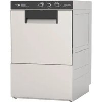
SteelTech 44 - Dishwasher Colged - Free user manual and instructions
Find the device manual for free SteelTech 44 Colged in PDF.


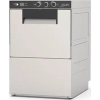
| Product Type | Professional Dishwasher |
| Brand | Colged |
| Model | SteelTech 44 |
| Category | Front-loading Dishwasher |
| Power Supply | Three-phase 400 V or single-phase 230 V depending on version (H07RN-F cable) |
| Water Supply | Max temperature 50 °C, max pressure 4 bar (400 kPa), min flow rate 20 L/min |
| Wash Programs | P1 (rapid), P2 (medium), P3 (long), G2 (standard glasses), G3 (intensive glasses), C1 (cups), CL (final rinse), dr (drain) |
| Capacity | Not specified (professional, generally large volume) |
| Noise Level | LpA max 55 dB (under-counter) / 65 dB (hood) / 76 dB (utensil washer) |
| Integrated Softener | Optional, with resin regeneration by salt addition |
| Dispensers | Integrated detergent and rinse aid dispensers, adjustable |
| Self-diagnosis | Yes, error codes Er01 to Er40 with descriptions |
| Drainage | By gravity or with drain pump (option) |
| Filtration | Removable integral filter, regular cleaning recommended |
| Wash Arms | Removable for nozzle cleaning |
| Tank Material | Stainless steel |
| Exterior Material | Steel sheet |
| Operating Ambient Temperature | 4 °C to 40 °C (average 30 °C) |
| Maximum Altitude | 2000 m |
| Compliance | EN/IEC 61000-3-11, NFC 15-100 |
Frequently Asked Questions - SteelTech 44 Colged
User questions about SteelTech 44 Colged
0 question about this device. Answer the ones you know or ask your own.
Ask a new question about this device
Download the instructions for your Dishwasher in PDF format for free! Find your manual SteelTech 44 - Colged and take your electronic device back in hand. On this page are published all the documents necessary for the use of your device. SteelTech 44 by Colged.
USER MANUAL SteelTech 44 Colged
Fig. 1
![graph LR A["1"] --> B["↓"] B --> C["PI"] C --> D["PI"] D --> E[": Green OK"] E --> F["Green OK"]](/content/2026/05/753760/images/ab6fd7db4c21dce3331cbbb4d49ac2dae325b41baa3f5ecfee2319248658020e.jpg)
Fig. 2
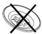
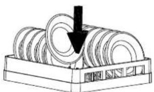

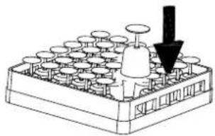


Fig. 3

g. 4
![graph LR A["3"] --> B["60"] B --> C["80"] C --> D[": P1"] D --> E["OK"]](/content/2026/05/753760/images/951b3a0a3fc92de825de75d41b6ed7450bf2601cbb3077c09762d13d59cecb78.jpg)
Fig. 5
![graph TD A["Window with Oven"] --> B["Step 3: Opening to Air Room"] B --> C["Step 3: 5 sec."] C --> D["45mm Screen"]](/content/2026/05/753760/images/b35e76e285c62b7c06e4f45a966a04b1dff17716b0f2bf2506f76dc303fd6e76.jpg)
Fig. 6
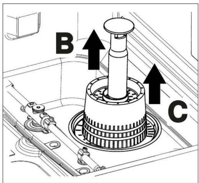
Fig. 8
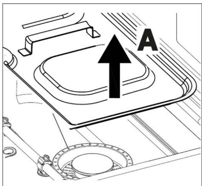
Fig. 7

![graph TD A["3"] --> B["dr"] B --> C["- - -"] D["Starburst Shape"] --> E["Square Box"] F["Circle"] --> G["Square Box"] H["Square"] --> I["Square Box"]](/content/2026/05/753760/images/a946b5ae6d4600e1a1e720534e761a87864d7c63d2f8948589f050b44a800ff8.jpg)
Fig. 9
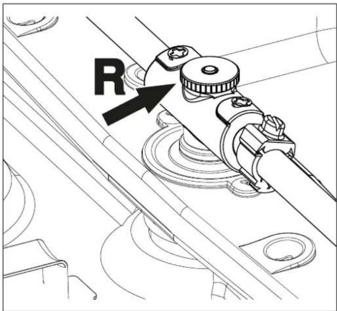
Fig. 10
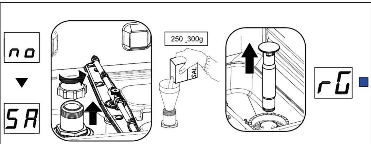
Fig. 11
INSTRUCTION MANUAL FOR DISHWASHERS
TRANSLATION OF ORIGINAL INSTRUCTIONS
CONTENTS
CHAP 1 RISKS AND IMPORTANT WARNINGS....2
1.1 NORMAL OPERATING CONDITIONS ....3
CHAP 2 PREFACE ....3
2.1 WARNINGS ....3
2.2 WARRANTY 3
2.3 STORAGE 3
CHAP 3 INSTALLATION ....4
3.1 UNPACKING......4
3.2 POSITIONING 4
3.3 ELECTRICAL CONNECTION 4
3.4 HYDRAULIC CONNECTION ....5
3.5 CONNECTION TO THE DRAIN LINE 6
3.6 RINSE AID AND DETERGENT 6
CHAP 4 USING THE MACHINE....7
4.1 KEY AND SYMBOLS....7
4.2 SWITCHING THE DISHWASHER ON 7
4.3 FILLING THE RACK....7
4.4 CYCLE SELECTION AND START-UP 7
4.5 PROGRAMS 8
4.6 AUTOMATIC CYCLE START-UP 9
4.7 REMOVING THE INTEGRAL FILTER 9
4.8 EMPTYING THE DISHWASHER....9
4.8.1 Appliances with no drain pump 9
4.8.2 Appliances with drain cycle (*optional) 9
4.9 TURNING THE DISHWASHER OFF 9
4.10 RESIN REGENERATION (*OPTIONAL)....9
4.11 DISPLAYING INFORMATION 10
4.12 LIST OF VIEWABLE MESSAGES .... 10
4.13 END OF SHIFT 10
CHAP 5 MAINTENANCE....11
5.1 GENERAL RULES....11
5.2 CLEANING 11
5.3 CLEANING THE FILTER UNIT 11
5.4 CLEANING THE ARMS....11
5.5 DISPENSERS....11
CHAP 6 SELF DIAGNOSTICS....12
CHAP 7 ADJUSTMENTS AND SETTINGS....14
7.1 INTEGRATED SOFTENER HARDNESS SETTING....15
CHAP 8 SCRAPPING....16
CHAP 9 ENVIRONMENT ...... 16
9.1 RESPECT FOR THE ENVIRONMENT 16
The manufacturer retains ownership of this document according to the time limits laid down by law, a reproduction and dissemination by any means without its prior written authorisation is prohibited.
N.B. The manufacturer reserves the right to modify the electrical, technical and aesthetic features of this appliance and replace any of its parts without notice, as he deems necessary to offer a product with a long service life and advanced technology.
CHAP 1 RISKS AND IMPORTANT WARNINGS

Read the instruction manual carefully before starting the machine. It contains important information regarding safe installation, use and maintenance. Failure to observe the instructions in the enclosed documentation may compromise appliance safety and immediately voids the warranty.
- This appliance is intended solely for the use for which it was designed. Any other use is deemed improp therefore hazardous.
- The specialised technician responsible for installing the appliance must instruct the user on its operation a attendant safety measures, including practical demonstrations.
- Only the manufacturer or an authorised service centre with qualified staff may work on the machine, ever of malfunction, using only original spare parts.
- Always disconnect or isolate the machine from its power and water supplies before servicing, repairing or cleaning it.
- The machine must NOT be used by untrained persons.
- The appliance may be used by children aged at least 8 years old or persons with reduced physical, sense mental capacities, or with no experience or knowledge, provided they are supervised or after they have r training in the safe use of the appliance.
• Children must not play with the appliance.
- Cleaning and maintenance by the user must not be performed by unsupervised children.
- The machine must NOT remain switched on when not in use.
- If the machine is not fitted with a plug or other means of complete disconnection with separation of all th contacts, these disconnection devices must be incorporated into the power mains, in compliance with the installation rules.
- If the power cable is damaged, it must be replaced by the manufacturer or an authorised technical assist service, or in any case by a person with similar qualifications, to prevent any risk.
- The screw on the appliance marked with the IEC 60417 standard symbol 5021 represents the equipotential connection.
- NEVER open the machine quickly if it has not completed its cycle.
- NEVER use the machine without the protection devices arranged by the manufacturer.
- NEVER use the machine to wash objects of type, shape or material not guaranteed as machine washable or not perfectly intact.
- NEVER use the appliance or any of its parts as steps or a support for people, property or animals.
- NEVER overload the open door of front-loading machines, which is rated only to support the rack loaded with dishes.
- NEVER place your bare hands in the wash solution.
- NEVER overturn the machine after it has been installed.
• If you notice any malfunction or fluid leak, immediately disconnect the power supply and shut off the water supply.
- Do not install the dishwasher near heat sources over 50°C .
- NEVER leave the dishwasher exposed to the weather (rain, direct sunlight, etc.)
- The dishwasher may not be installed outdoors without proper cover.
- Never start a wash programme without the overflow in the tub, as applicable.
- Never place magnetic objects in the vicinity of the machine.
- Do not use the top of the machine as a table or support.
- The installer is responsible for checking that the grounding system is fully operational.
- At the end of testing, the installer must issue a written declaration stating that the machine has been installed tested in accordance with established legislation and good practice.
- DO NOT change the position of or tamper with the machine's parts, as this could compromise its safety.
- Noise pressure level according to EN ISO 4871:
- LpA Max = 55db Kpa=2.5db for undercounter versions
- LpA Max = 65db Kpa=2.5db for hood versions
- LpA Max = 76db Kpa=1.5db for utensil washer versions.
- Max inlet water temperature: 50°C .
• Max inlet water pressure: 4 bar (400 kPa).
- Appliance designed for permanent connection to the water supply.
- Do not clean the appliance with steam or water jets.
• Max unloading height: - On the ground in versions with overflow.
• Maximum height 1 m in versions with drain pump.
1.1 Normal operating conditions
Ambient temperature:
Altitude: Up to 2000 metres
Relative humidity:
Max 30% at 40°C / max 90% at 20 °C
CHAP 2 PREFACE
2.1 Warnings
Keep all documentation in the vicinity of the appliance; make it available to the technicians and operators charged with operating it and keep it in good condition in a safe place, along with extra copies for frequen
The operator must read, understand and familiarise himself with the contents of this manual bef working on or with the appliance.
The appliance is intended solely for professional heavy duty dishwashing applications and must be installed, operated and serviced only by qualified persons according to the manufacturer's instructions.
2.2 Warranty
The manufacturer is not liable for any damage or injury resulting from failure to observe the instructions or improper use of the machine.
Failure to observe the instructions in the enclosed documentation may compromise appliance safety and immediately voids the warranty.
Installation and repair by unauthorised technicians and the use non-original spare parts immediately void the warranty.
2.3 Storage
Transport and warehousing: Between -10°C and 55°C with peaks up to 70°C (for max 24 hours).
CHAP 3 INSTALLATION
Proper installation is essential to the good operation of the appliance. Some of the data required for installation of the appliance are given on the nameplate on its RH body panel, and a copy is included on the cover p this manual.

The appliance may only be installed by qualified persons authorised to do so.
3.1 Unpacking
Check the condition of the packaging, and note any evident damage on the shipping bill. Remove the pack and check that the appliance is in good condition; immediately report any damage to the reseller and the shipping agent by fax or registered letter with return receipt. If the damage is such as to compromise the s of the appliance, do not install or operate it until it has been inspected by a qualified technician.

The packaging (plastic bags, expanded polystyrene, nails, etc.) is hazardous and must not left within the reach of children or pets.
3.2 Positioning
- Check that there are no objects or materials in the installation area which may be damaged by the steam emitted by the appliance during operation, or if there are, make sure they are properly protected.
- Before positioning the dishwasher, set up the electrical power supply, water supply and drain connections.
- For flush-mounting single panel machines, leave a space of at least 10 mm between machine walls and the adjacent surfaces.
- The floor or build-in unit must be rated to support the weight of the appliance.
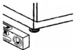
- To ensure that it is stable, level the appliance with its four feet.
- The appliance is intended for fixed installation only; any other approaches must be agreed with and approved by the manufacturer.
- Remove the protective film from its body panels before operating the dishwasher.
3.3 Electrical connection
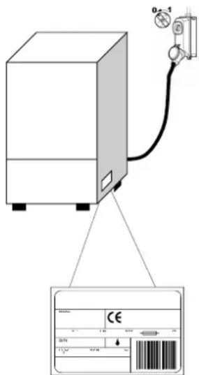
- The power supply must be fitted with a omnipolar circuit breaker (master power switch) to break all contacts including neutral, with a contact gap of at least 3 mm and the cutout or fuses, which must be set or rated to the power indicated on the machine nameplate.
- The master power switch must be fitted to the power line in the vicinity of the insta and may be connected to only one machine at a time.
- The mains voltage and frequency must match the nameplate ratings.
- The installation must include a grounding system conforming with established electric safety legislation, to protect the operator and the appliance itself.
- This appliance conforms to EN/IEC 61000-3-11 certification if the system impedances less than or equal to Zmax in the point of interface between the user's supply system and the public system. The installer or app user is responsible for checking that the appliance is connected exclusively to a supply with system impedance Zsys less than or equal to Zmax .
| Zmax | |
| Utensil washers 0.21 Ω | |
| Hood 0.24 Ω | |
| Undercounter 0.41 Ω |
- The power cable, which must be exclusively typeH07RN-Fwith current capacity at 60°C on the cable:
Three-phase machine
-5x2.5 mmup to 20 A
-5x4 mmup to 30 A
-5x6 mmup to 38 A
-5x10 mmup to 54 A
Single-phase machines
-3x1.5 mmup to 16 A
-3x2.5 mmup to 25 A
- Must not be stretched or crushed during normal operation or routine maintenance.
- The appliance must also be connected to an equipotential system, connected by a screw marked by the 5021 -IEC 60417.
- The equipotential cable must have a cross section of 10. mm
- Respect the polarities indicated in the wiring diagram.
- For further information, refer to the wiring diagram.

Do not use multi-sockets, adapters, cables of an inadequate cross-section or type or with extensions not conforming to established electrical installation regulations.
3.4 Hydraulic connection
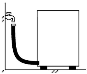
The appliance must be connected to its water supply with a flexible hose. A shut valve (cock) must be installed between the water supply line and the appliance's solenoid valve. The cock must be close to the appliance.
- The water supply, temperature and pressure must be compatible with the ratings shown on the technical data plate on the machine.
- Make sure that the water supply flow rate is no less than 20 l/min.
- If the water hardness is greater than 14°f (8 °dH), we recommend using an internal water softener. If the hardness is greater than 35°f (19.5 °dH), install an external water softener upline of the solenoid valve.
- For machines without water softener: if the water hardness is greater than 14°f (8 °dH), install an exterr softener upline of the solenoid valve.
-
If the water has a very high residual concentration of high conductivity minerals, we recommend installing demineralisation system.
-
Machines intended for use with desalinated water or in any case with high sodium chloride concentration be ordered specifically, as they require specific construction materials
- Do not supply fully demineralised water to machines with a heat recovery unit with batteries with copper this case, request the version with batteries with stainless steel pipes.
3.5 Connection to the drain line
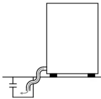
Free drain
- The drain line must consist of a free drain sump with siphon suited to the capacity of the drain hose supplied with the appliance. The hose must be able to reach the sump without stretching, restriction, folding, crushing, pressing or forcing in any way.
- The tub drains under gravity, so the drain sump must be lower than the machine's base.
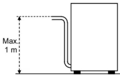
With drain pump (available on request)
- If the drain is not lower than the base of the appliance, you can use the version with drain pump (available on request).
- In this case, the drain connection may be no higher than 1 m.
• Always check that the drain works properly and is not blocked. - Any other solution must be approved by the manufacturer in advance.
3.6 Rinse aid and detergent
- The rinse aid and detergent are dispensed by the machine's integral dispenser (depending on model).
- The dose is set by the installer in relation to the hardness of the water, and he also calibrates the dispethemselves.
- Before calibrating them, fill the dispenser supply tubes with their respective product.
- The units are calibrated with the adjuster screws, or directly with the control panel (as applicable).
- The level of fluid in the container must be sufficient for priming; do not allow it to drain completely or top it up with corrosive or impure product.
NEVER use CHLORINE or HYPOCHLORITE based detergents.
We recommend installing an automatic detergent dispenser.
CHAP 4 USING THE MACHINE
4.1 Key and symbols
Referring to (Fig. 1)
| 1 ON/OFF BUTTON 5 RINSE LED | ||
| 2 PROGRAMME SELECTION BUTTON 6 WASH LED | ||
| 3 START BUTTON 7 STATUS LED | ||
| 4 INFORMATION DISPLAY |
4.2 Switching the dishwasher on
Referring to (Fig. 2):
- Turn on the main power switch and open the external water tap.
- Check the presence of the overflow.
- Press ON/OFF (1).
• Water loading begins automatically when the machine is switched on. - The point on the display flashes until the level is reached.
- When the working temperature is reached, the STATUS LED (7) stays on, lit in green.
- The optimal wash conditions have been reached.
- The WASH (6) and RINSE (5) LEDs light up alternately to indicate that the tub and boiler heating are on.
4.3 Filling the rack
Referring to (Fig. 3), to ensure the correct operation of the dishwasher, follow the rules described below:
- Use a suitable rack, fill without overloading and without overlapping the dishes.
- Always wipe the dishes before placing in the dishwasher; do not put dishes with dry or solid residues in washer.
- Place the empty dishes in the rack facing downwards.
- Place plates and the like in the sloping rack, with the inner surface facing upwards.
- Place the cutlery in the cutlery basket, handle end down.
- Do not place silver and stainless steel cutlery in the same cutlery basket as this will turn the silver brown corrode the steel.
- Wash the dishes immediately after use, in order to prevent any residue from hardening and sticking on th
- Use only solid, dishwasher-proof dishes.
4.4 Cycle selection and start-up
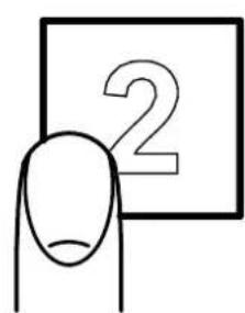
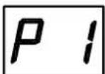
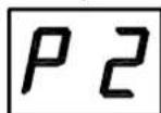
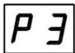
- Press the PROGRAMME SELECTION (2) button repeatedly to select a wash cycle that is suitable for the dishes to be washed; the display will show the cycle number chosen (Fig. 4).
- To start the programme, press the START (3) button; the WASH (6) and RINSE (5) LEDs will flash to indicate the cycle phase, while the display will indicate the respective temperature.
- Once the cycle is complete, the STATUS LED (7) lights up in green (Fig. 5).
- For rapid drying, remove the rack from the machine as soon as the cycle finishes.
- To stop a wash cycle early, press the START (3) button.
N. B. In hood versions, after the first work cycle the automatic start is automatically enabled; the subsequent cycles will be enabled automatically when the hood is closed. This operating mode is marked on the display by "AS".
4.5 Programs
| P1 | Lightly soiled dishes, short wash programme. |
| P2 | Averagely soiled dishes, medium wash programme. |
| P3 | Heavily soiled dishes, long wash programme. |
| G2 | Standard glass cycle. |
| G3 | Intensive glass cycle. |
| C1 | Cup cycle. |
| CL | Drain and self-cleaning cycle to be used at the end of working day. |
| dr | Drain cycle. |
Caution:
The special programmes vary according to the dishwasher model.
4.6 Automatic cycle start-up
This function is used to make the chosen cycle start automatically when the door is closed. To enable, pro as follows (Fig. 6):
- If not made available by default, the function must first be enabled via the settings menu.
- With the appliance on and the door open, press and hold (for at least 5 seconds) the START (3) button until AS shows on the display.
- To disable the function, with the door open press START (3) again for five seconds.
4.7 Removing the integral filter
- Move the washing and rinsing arms at right angles to the edge of the door (Fig. 7).
If the dishwasher has a 3-arm wash arm, it must be removed in order to remove the integral filters.
- Lift each semi-filter by the relative handle.
4.8 Emptying the dishwasher
4.8.1 Appliances with no drain pump
- Switch the dishwasher off.
- If present, remove the integral filter (Fig. 7 A).
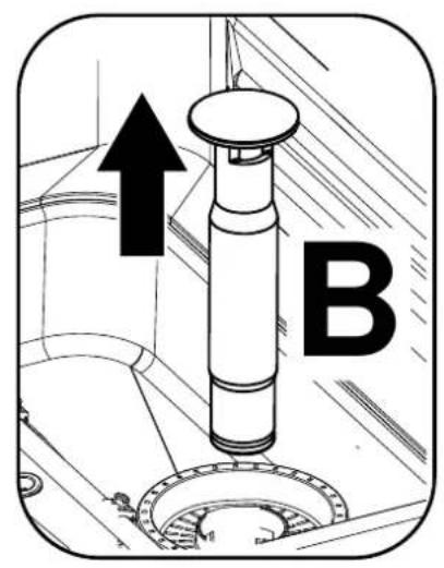
- Pull up and remove the overflow pipe (Fig. 8 B).
- Wait for the tub to empty completely.
- If necessary, extract the tub filter and clean it (Fig. 8 C).
4.8.2 Appliances with drain cycle (*optional)
- If present, remove the integral filter (Fig. 7 A).
- If present, remove the overflow pipe by pulling it upwards (Fig. 9).
- Close the door.
- Select cycle dr.
- Press START (3) to start the cycle.
- If necessary, extract the tub filter and clean it (Fig. 8 C).
- The machine runs a drain cycle with self-cleaning (*where foreseen) and then switches off.
4.9 Turning the dishwasher off
- To switch the machine off, press ON/OFF (1); on the DISPLAY (4) the central segments will remain displayed to indicate the presence of voltage.
4.10 Resin regeneration (*optional)
In machines fitted with water softener, when the warning SA Lt appears, you should add salt to the relative container; proceed as follows:
- Remove the rack from the machine.
- Remove the integral filter (Fig. 7).
- Unscrew the cap on the salt container (Fig. 11).
- Pour in approx. 300g of large-grain kitchen salt, using the funnel supplied. (when filling for the first time, fill the tank firstly with water).
- Close the container firmly.
- Rinse the area around the salt cap by hand and run a self-cleaning cycle to prevent possible corrosion is
- The warning SA Lt will disappear after a few minutes.
The warning rG on the display indicates that the machine is running a resin regeneration cycle, which is necessary for the water softener to work correctly; while this warning is shown, cycles that have been started could run longer than usual.
N.B. Do not switch off the machine if a regeneration cycle is underway.
4.11 Displaying information
- By holding the START (3) button pressed for a few seconds you can display in sequence the Boiler temperature, the Tub temperature and the number of cycles performed by the machine.
This information can be displayed both before and during the wash cycle and will only be visible tempor - By holding the PROGRAMME SELECTION (3) button pressed for a few seconds you can display in sequence the Boiler temperature, the Tub temperature, permanently and for all programmes.
- The function can be deactivated by holding the PROGRAMME SELECTION (3) button pressed for a few seconds.
4.12 List of viewable messages
| do | Door open | AS Automatic | start enabled |
| b | Rinse temperature | no dt | No detergent |
| t | Wash temperature | no bl No rinse | aid |
| rG | Regeneration system on | CH | Menu key |
| SA Lt No salt | in the softener Fu Firmware | are revision | |
| Cy | Number of cycles carried out | Su Software code |
4.13 End of shift
- At the end of the day, always drain the machine as described in section 4.8 Emptying the dishwasher.
- Disconnect the power supply by means of the main switch and close the external water cock.
• Perform routine maintenance and clean the machine as described in section CHAP 5 MAINTENANCE. - If possible, leave the door ajar to prevent bad odours building up inside the machine.
CHAP 5 MAINTENANCE
5.1 General rules

Before doing any maintenance, completely drain out all water, shut off the power supply close the water supply cock.
Do not use water under pressure - it can damage the electrical equipment. Only wash the body panelling is cold, using only products specifically designed for steel.
If there is a risk of ice forming, drain the water from the boiler and wash pump.
5.2 Cleaning
To keep the machine in good working order, it must be maintained regularly as explained below. We recon periodically running a sanitising treatment with suitable non-corrosive commercial products.
5.3 Cleaning the filter unit
Run this procedure at the end of the day or when you see the filters are dirty:
- Remove and clean the racks.
- Empty out the tub as explained in section 4.8 Emptying the dishwasher.
- Remove and carefully clean all the filters.
- Do not use abrasive products to clean the tub.
- Restore all removed parts when finished.
5.4 Cleaning the arms
The wash and rinse arms are easily removed in order to clean their nozzles and prevent blockage/encrusta
Proceed as follows (Fig. 10):
- Remove the spray arms by unscrewing the retaining nuts or by unclipping the quick-fit attachments on ma so equipped.
- Wash all parts under a jet of running water and clean the nozzles thoroughly, using a toothpick or pointe necessary.
- Clean the arm rotation pins inside the machine and the wash and rinse water drainage area.
- Restore the arms and check that they rotate freely.
5.5 Dispensers
To ensure that the dishwasher operates efficiently, the tubes inside the detergent and rinse aid dispensers be replaced periodically.
The tubes have a service life that can vary depending on the chemicals used.
We recommend that you periodically check the condition of the tubes and plan to replace them at least on year.
CHAP 6 SELF DIAGNOSTICS
The machine is equipped with a self-diagnosis system that registers and warns of a number of malfunctions
| Fault | Description and possible remedies | |
| Er01 | No rinsing. The rinsing cycle was not completed correctly. Make sure that the rinsing nozzles are clean. | |
| Er02 | No water drained. The water was not drained or drained incorrectly. Check that the drain pipe is not bent or crushed and that the siphon and filters are not blocked. In machines fitted with an overflow pipe, remove this before starting the drainage cycle. | |
| Er03 | Rinse temperature reset fault. The boiler temperature did not reset in the set time during the washing cycle. Switch the machine off and then on and run a new cycle. | |
| SAFE | Er04 | Water filling in tank fault. Make sure the pipes are connected correctly, and that the water tap is open. Where foreseen, check the presence of the overflow. Switch the dishwasher off and then on and fill again. |
| Er05 | Tank thermometer fault. (Probe open) The machine does not read the tank temperature value. Switch the dishwasher off and then on. | |
| Er06 | Tank thermometer fault. (Probe short circuited) The machine does not read the tap temperature value. Switch the dishwasher off and then on. | |
| Er07 | Boiler thermometer fault. (Probe open) The machine does not read the boiler temperature value. Switch the dishwasher off and then on. | |
| Er08 | Boiler thermometer fault. (Probe short circuited) The machine does not read the boiler temperature value. Switch the dishwasher off and then on. | |
| Er09 | Boiler loading timeout: boiler not filled. Impossible to carry out rinse cycle. Check that the water tap is open. Switch the dishwasher off and then on and run a new cycle. | |
| Er21 | Insufficient rinse The right amount of rinsing did not take place; make sure the rinse nozzles are clean. The error does not block the machine. | |
| Er22 | Tank temperature reset fault: The tank temperature did not reset in the set time due the washing cycle. Switch the machine off and then on and run a new cycle. | |
| Er25 | Run external regeneration: The number of litres set for external water treatment equipment has been reached, the error does not prevent dishwasher operation, the message can be reset from the settings in menu 12. | |
| SAFE | ErSF | Electro-mechanical safety device: The boiler or tub safety thermostats have been tripped, or the tub safety pressure switch has been triggered. |
| ErSL | Level safety switch: Incorrect water level in the tank. | |
| Erb | Excessive Boiler Temperature: Probable heating contactor /relay failure | |
| Ert | Excessive Tub Temperature: Probable heating contactor /relay failure | |
| drt | Dirty filter: Incorrect water level in tub, caused by dirty filter or poorly inserted overflo | |
| ErSI | Supply safety error: Fatal error, contact a technical assistance centre. | |
| Er98 | Soft start error: Soft start system error, contact a technical assistance centre. | |
| NO SALT | No salt: In dishwashers with water softener, this means that there is no salt.Add salt. | |
| Fault | Description and possible remedies | |
| NO DT | No detergent: Add detergent in the priming tank. | |
| NO BL | No rinse aid: Add rinse aid in the priming tank. | |
| SERV | Maintenance required: General maintenance is required, if pre-set. | |
| REG ON | Regeneration in progress: the regeneration cycle for the water softener resin is underway. | |
| REG REQ | Regeneration Required: Start the regeneration if not automatically scheduled. | |
| Er27 | Boiler gradient error: The boiler is not heating correctly. | |
| Er28 | Tub gradient error: The tub is not heating correctly. | |
| Er99 | Auxiliary board error: Communication with the auxiliary board is not correct. | |
| Er30 | Automatic open error: In dishwashers with hood with automatic open, the opening system is not operating correctly.Check that nothing is stopping the hood from opening.If the problem persists, contact a technical assistance centre. | |
| Er31 | Automatic close error: In dishwashers with hood with automatic open, the closing system is not operating correctly.Check that nothing is stopping the hood from closing.If the problem persists, contact a technical assistance centre. | |
| Er33 | Osmosis with minimum pressure: Check that the water tap is open. | |
| Er34 | Osmosis water loss: Close the power and water supply for the dishwasher; contact a technical assistance centre. | |
| Er35 | Osmosis conductivity error: Osmosis system does not work properly, contact a technical assistance centre. | |
| Er36 | Osmosis filter: The osmosis filter needs to be replaced; contact a technical assistance centre. | |
| Er37 | Boiler heating timeout: The rinse water heating element does not work properly, contact a technical assistance centre. | |
| Er38 | Tub heating timeout: The wash water heating element does not work properly, contact a technical assistance centre. | |
| Er39 | Faulty boiler pressure switch. | |
| Er40 | Faulty tank pressure switch. | |
 Switching the dishwasher off and then on again "resets" the signals, if after carrying out instructions given the problem persists, contact an Authorised Service Centre. Switching the dishwasher off and then on again "resets" the signals, if after carrying out instructions given the problem persists, contact an Authorised Service Centre. | ||

The following settings should only be configured by a qualified technician.
The parameters listed below can be set during installation or afterwards, accessing the settings menu as follows:
• Machine in standby with door open.
- Press buttons 2 and 3 (PROGRAMME SELECTION and START) simultaneously for 5 seconds and insert key CH 12 (buttons 2 and 3 to change the parameter, 1 to confirm).
- Then, by repeatedly pressing button 1 (ON/OFF) you can scroll through the options and activate and/or edit them using buttons 2 and 3.
- If you press and hold button 1, you can exit programming mode and the change will be saved. The list of parameters may vary according to the type of machine.
| Language | Select language. | |
| b | Boiler Temperature | Adjust the boiler temperature for programmes. Versions with atmospheric boiler (rinse pump) have different settings for each programme (b1 - b2 - b3). |
| t | Tank Temperature | Tub temperature regulation for programmes. Versions with rinse pump have different settings for each programme (t1 - t2 - t3) |
| tH | Thermo - Stop Activation of ThermoStop function which ensures correct rinse temperature. | |
| ES | Energy Saving Activation of Energy Saving function which allows energy-savings to be made when the machine is switched on but not in use. | |
| dn | Detergent Pump Manual operation of detergent dispenser. | |
| bn | Rinse Aid Pump | Manual operation of rinse aid dispenser. |
| rn | ManualRinse | Manual operation of rinse pump. |
| dt | Dosage Detergent Detergent dosing time. | |
| bl | Dosage Rinse Aid | Rinse aid dosing time. |
| dH | WaterHardness | Input water hardness setting (machines with water softener): enter the values with reference to the table below. |
| CC | Set Number Service Cycles | Cycle counter setting and activation to enable the Service alert for an external water softener.The “Service” alert can be cancelled by holding pressed all 3 buttons with the machine off and the door open. |
| CLS | Water Service Set | Setting of litres of autonomy for external water treatment equipment, adjustment setting from 0 to 12000 litres in steps of 200. |
| AA | Autostart Autoenabling | Automatic start enabled. |
| dr | Manual Drain | Manual operation of drain pump. |
Once all necessary parameters have been set, to save and exit simply press and hold button 1 until the o dashes appear.
7.1 Integrated softener hardness setting
Set the supply water hardness degree, dH, in the settings menu as shown in the following table:
| Measured hardness dH | Measured hardness dH | |||
| °fr dGH | n° °fr dGH n° | |||
| 0 ÷ 20 0 ÷ | 11 1 41 ÷ 45 23 ÷ 25 6 | |||
| 21 ÷ 25 12 | ÷ 14 2 46 ÷ 50 26 ÷ 28 7 | |||
| 26 ÷ 30 15 | ÷ 17 3 51 ÷ 55 29 ÷ 31 8 | |||
| 31 ÷ 35 17 | ÷ 20 4 56 ÷ 60 31 ÷ 34 9 | |||
| 36 ÷ 40 20 | ÷ 22 5 | |||
Our machines do not contain materials requiring special handling.
N.B. (Applicable in the EU and countries with sorted waste disposal).
The mark applied to the product or its documentation indicates that it must not be scrapped with domestic when it reaches the end of its service life. To prevent damage to the environment or health risks due to in scrapping, keep this product separate from other waste and recycle it so as to promote sustainable use of
Corporate users are requested to contact their supplier and check the terms and conditions of the purchase contract.
The product may not be scrapped together with other commercial waste.
| Can be recycled directly | Symbols Object | Material % | |||
 | Sheet Steel | 80 | |||
 | Cardboard packaging | PAP | |||
 | Wooden pallet | ISPM15 | |||
 | Plastic parts | PP, PP+FV | |||
| Compounds | 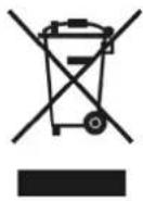 | WEEE | Motors | Assemblies | 20 |
| Electric parts | |||||
| Electronic parts | |||||
| Rubber parts | EPDM | ||||
CHAP 9 ENVIRONMENT
9.1 Respect for the environment
Proper use of the dishwasher can improve its environmental footprint, if the following simple rules are obse
- Only wash full racks.
- Switch the dishwasher off when not using it.
- Keep the machine closed when it is in standby.
- Use wash programmes suited to the amount of soiling.
• Supply the machine with hot water, if gas heated. - Make sure the drains flow into a suitable sewer.
- Do not exceed the recommended dose of detergent.
Freier Ablauf
CHAP 3 INSTALLATION ....4
3.1 DÉBALLAGE 4
3.2 EMPLACEMENT 4
3.3 BRANCHEMENT ÉLECTRIQUE....4
3.4 BRANCHEMENT SUR L'ARRIVÉE D'EAU....5
3.5 BRANCHEMENT À L'ÉVACUATION DES EAUX USÉES....6
3.6 LIQUIDE DE RINÇAGE ET DÉTERGENT....6
CHAP 4 UTILISATION DU LAVE-VAISSELLE....7
4.1 LÉGENDE ET SYMBOLES....7
4.2 ALLUMAGE 7
4.3 PRÉPARATION DU PANIER....7
4.4 SÉLECTION ET DÉMARRAGE DU CYCLE....7
4.5 PROGRAMMES 8
4.6 DÉMARRAGE AUTOMATIQUE DU CYCLE....9
4.7 DÉPOSE DU FILTRE INTÉGRAL....9
4.8 VIDANGE DE L'APPAREIL 9
Évacuation libre
Scarico libero
Desagüe libre
Descarga livre
2.1 WAARSCHUWINGEN....3
2.2 GARANTIE ....3
2.3 OPSLAG 3
HOOFDSTUK 3 INSTALLATIE ....4
3.1 UITPAKKEN 4
3.2 PLAATSING 4
3.3 ELEKTRISCHE AANSLUITING 5
3.4 AANSLUITING OP HET WATERNET 6
3.5 VERBINDING MET DE AFVOERLEIDING....7
3.6 GLANSMIDDEL EN VAATWASMIDDEL....7
HOOFDSTUK 4 GEBRUIK VAN DE MACHINE ....8
4.1 LEGENDA EN SYMBOLEN 8
4.2 AANZETTEN 8
4.3 VOORBEREIDING REK....8
4.4 PROGRAMMAKEUZE EN -START 8
4.5 PROGRAMMA'S....9
4.6 AUTOMATISCHE CYCLUS STARTEN....10
4.7 HET INGEBOUWDE FILTER VERWIJDEREN....10
4.8 DE MACHINE LEGEN 10
Vrije afvoer
Er40 Drukschakelaar bak defect.

1.1 NORMALE DRIFTSFORHOLD 3
KAP. 2 FORORD....3
2.1 ADVARSLER....3
2.2 GARANTI....3
2.3 OPBEVARING 3
KAP. 3 INSTALLATION ....4
3.1 UDPAKNING......4
3.2 PLACERING 4
3.3 ELTILSLUTNING 4
3.4 HYDRAULISK TILSLUTNING 5
3.5 TILSLUTNING TIL AFL∅B 6
3.6 AFSPÆNDINGSMIDDEL OG VASKEMIDDEL 6
KAP. 4 BRUG AF MASKINEN....7
4.1 OVERSIGT OG SYMBOLER 7
4.2 TÆNDING 7
4.3 FORBEREDELSE AF KURVEN....7
4.4 VALG OG START AF CYKLUS 7
4.5 PROGRAMMER 8
4.6 START AF AUTOMATISK CYKLUS 9
4.7 FJERN INTEGRERET FILTER....9
4.8 T∅MNING AF MASKINEN 9
4.9 SLUKNING AF MASKINEN....9
4.10 REGENERERING AF HARPIKS (*EKSTRAUDSTYR) 9
4.11 VISNING AF INFORMATION .... 10
4.12 LISTE OVER MEDDELELSER, DER KAN VISES....10
4.13 SLUT PÅ DRIFT 10
KAP. 5 VEDLIGEHOLDELSE....11
5.1 GENERELLE REGLER 11
5.2 RENG∅RING....11
5.3 RENSNING AF FILTERAGGREGAT 11
5.4 RENG∅RING AF ARME....11
5.5 DISPENSERE....11
KAP. 6 SELVDIAGNOSE....12
KAP. 7 JUSTERINGER OG INDSTILLINGER....14
7.1 INDSTILLING AF HÅRDHED INDBYGGET BL∅DG∅RINGSANLÆG....15
KAP. 8 BORTSKAFFELSE ...... 16
KAP. 9 MILJ∅ 16
9.1 BRUG MED RESPEKT FOR MILJ∅ET 16
Frit afløb
INNEHÅLLSFÖRTECKNING
KAP 1 RISKER OCH VIKTIGA VARNINGAR....2
1.1 NORMALA ANVÄNDNINGSVILLKOR....3
KAP 2 FÖRORD ....3
2.1 VARNINGAR....3
2.2 GARANTI....3
2.3 FÖRVARING....3
KAP 3 INSTALLATION....4
3.1 UPPACKNING 4
3.2 PLACERING 4
3.3 ELEKTRISK ANSLUTNING 4
3.4 VATTENANSLUTNING....5
3.5 ANSLUTNING TILL AVLOPPET 6
3.6 GLANSMEDEL OCH DISKMEDEL....6
KAP 4 ATT ANVÄNDA MASKINEN....7
4.1 TECKENFÖRKLARING OCH SYMBOLER 7
4.2 PÅSLAGNING 7
4.3 ATT LASTA DISKKORGEN 7
4.4 VAL OCH START AV PROGRAM....7
4.5 PROGRAM 8
4.6 AUTOMATISK PROGRAMSTART 9
4.7 ATT TA LOSS INTEGRALFILTRET 9
4.8 TÖMNING AV MASKINEN 9
4.8.1 Maskiner utan tömningspump....9
4.8.2 Maskiner med tömningsprogram (*tillval)....9
4.9 AVSTÄNGNING AV MASKINEN 9
4.10 REGENERERING AV HARTSER (*TILLVAL) 9
4.11 VISNING AV INFORMATION 10
4.12 LISTA ÖVER MEDDELANDEN SOM KAN VISAS 10
4.13 VID ARBETSDAGENS SLUT 10
KAP 5 UNDERHÅLL 11
5.1 ALLMÄNNA REGLER 11
5.2 RENGÖRING....11
5.3 RENGÖRING AV FILTERENHETEN 11
5.4 RENGÖRING AV DISK- OCH SPOLARMAR 11
5.5 DOSERARE....11
KAP 6 SJÄLVDIAGNOS....12
KAP 7 REGLERINGAR OCH INSTÄLLNINGAR ....14
7.1 INSTÄLLNING AV HÄRDHETSGRAN MED INTEGRERAD AVHÄRDARE 15
KAP 8 AVFALLSHANTERING....16
KAP 9 MILJÖ....16
9.1 MILJÖVÄNLIG ANVÄNDNING....16
Öppen avloppsbrunn
Vapaa poisto
Ελεύθερη αποχέτευση
- INSTRUCTION MANUAL FOR DISHWASHERS
- TRANSLATION OF ORIGINAL INSTRUCTIONS
- CONTENTS
- CHAP 1 RISKS AND IMPORTANT WARNINGS....2
- CHAP 2 PREFACE ....3
- CHAP 3 INSTALLATION ....4
- CHAP 4 USING THE MACHINE....7
- CHAP 5 MAINTENANCE....11
- CHAP 6 SELF DIAGNOSTICS....12
- CHAP 7 ADJUSTMENTS AND SETTINGS....14
- CHAP 8 SCRAPPING....16
- CHAP 9 ENVIRONMENT ...... 16
- CHAP 1 RISKS AND IMPORTANT WARNINGS
- 1.1 NORMAL OPERATING CONDITIONS
- CHAP 2 PREFACE
- 2.1 WARNINGS
- 2.2 WARRANTY
- 2.3 STORAGE
- CHAP 3 INSTALLATION
- 3.1 UNPACKING
- 3.2 POSITIONING
- 3.3 ELECTRICAL CONNECTION
- THREE-PHASE MACHINE
- SINGLE-PHASE MACHINES
- 3.4 HYDRAULIC CONNECTION
- 3.5 CONNECTION TO THE DRAIN LINE
- 3.6 RINSE AID AND DETERGENT
- CHAP 4 USING THE MACHINE
- 4.1 KEY AND SYMBOLS
- 4.2 SWITCHING THE DISHWASHER ON
- REFERRING TO (FIG. 2)
- 4.3 FILLING THE RACK
- 4.4 CYCLE SELECTION AND START-UP
- CAUTION
- 4.6 AUTOMATIC CYCLE START-UP
- 4.7 REMOVING THE INTEGRAL FILTER
- 4.8 EMPTYING THE DISHWASHER
- 4.8.1 APPLIANCES WITH NO DRAIN PUMP
- 4.8.2 APPLIANCES WITH DRAIN CYCLE (*OPTIONAL)
- 4.9 TURNING THE DISHWASHER OFF
- 4.10 RESIN REGENERATION (*OPTIONAL)
- 4.11 DISPLAYING INFORMATION
- 4.13 END OF SHIFT
- CHAP 5 MAINTENANCE
- 5.1 GENERAL RULES
- 5.2 CLEANING
- 5.3 CLEANING THE FILTER UNIT
- 5.4 CLEANING THE ARMS
- 5.5 DISPENSERS
- 7.1 INTEGRATED SOFTENER HARDNESS SETTING
- N.B. (APPLICABLE IN THE EU AND COUNTRIES WITH SORTED WASTE DISPOSAL)
- CHAP 9 ENVIRONMENT
- 9.1 RESPECT FOR THE ENVIRONMENT
- CHAP 4 UTILISATION DU LAVE-VAISSELLE....7
- HOOFDSTUK 3 INSTALLATIE ....4
- HOOFDSTUK 4 GEBRUIK VAN DE MACHINE ....8
- KAP. 2 FORORD....3
- KAP. 3 INSTALLATION ....4
- KAP. 4 BRUG AF MASKINEN....7
- KAP. 5 VEDLIGEHOLDELSE....11
- KAP. 6 SELVDIAGNOSE....12
- KAP. 7 JUSTERINGER OG INDSTILLINGER....14
- KAP. 8 BORTSKAFFELSE ...... 16
- KAP. 9 MILJ∅ 16
- INNEHÅLLSFÖRTECKNING
- KAP 1 RISKER OCH VIKTIGA VARNINGAR....2
- KAP 2 FÖRORD ....3
- KAP 3 INSTALLATION....4
- KAP 4 ATT ANVÄNDA MASKINEN....7
- KAP 5 UNDERHÅLL 11
- KAP 6 SJÄLVDIAGNOS....12
- KAP 7 REGLERINGAR OCH INSTÄLLNINGAR ....14
- KAP 8 AVFALLSHANTERING....16
- KAP 9 MILJÖ....16
Brand : Colged
Model : SteelTech 44
Category : Dishwasher