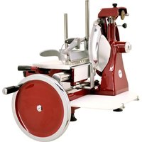
20013 - Slicer Omcan - Free user manual and instructions
Find the device manual for free 20013 Omcan in PDF.


| Product Type | Manual Meat Slicer |
| Brand | Omcan |
| Model | 20013 (MS-IT-0250-M) |
| Blade Diameter | 250 mm (9.8 inches) |
| Adjustable Slice Thickness | 0 to 20 mm (0 to 0.8 inch) |
| Net Weight | 33 kg (72.8 lb) |
| Materials | Aluminum alloy frame, stainless steel inserts |
| Power Source | Manual (handwheel) |
| Intended Use | Boneless meats (cooked or raw ≥ +3°C) and cold cuts |
| Main Functions | Manual slicing, progressive thickness adjustment, vertical pusher, sliding carriage, drive handwheel, quick product support advance |
| Safety | Adjustable blade guard, pusher with lock, cut-resistant gloves mandatory, vertical pusher lock button |
| Routine Maintenance | Daily cleaning with biodegradable detergent; weekly oiling of guide rails (carriage and product support) |
| Blade Sharpening | Periodic (approximately every 6 months) via built-in two-wheel sharpener |
| Recommended Lubricant | Omcan white mineral oil (ref. 39115) – do not use vegetable oil |
| Warranty | 1 year parts and labor (except misuse) |
| Item Number | 20013 |
| Manufacturer Model | 250VO |
| Certifications | CE, ETL Sanitation |
| Compliance Standard | EN 1974 |
| Optional Accessories | Floor stand – Omcan reference |
| Spare Parts Available | Blade, drive chain, sharpening wheels, white mineral oil |
| Repairability | Routine maintenance by user; complex interventions (blade replacement, internal parts repair) entrusted to an authorized center |
| Prohibited Cleaning Methods | Water jets, steam, dishwasher, and corrosive detergents |
Frequently Asked Questions - 20013 Omcan
User questions about 20013 Omcan
0 question about this device. Answer the ones you know or ask your own.
Ask a new question about this device
Download the instructions for your Slicer in PDF format for free! Find your manual 20013 - Omcan and take your electronic device back in hand. On this page are published all the documents necessary for the use of your device. 20013 by Omcan.
USER MANUAL 20013 Omcan
natural_image
Red industrial machine with ornate fan-shaped base and mechanical components (no visible text or symbols)
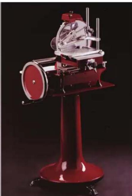
natural_image
Red industrial machine with mechanical components mounted on a stand against a dark background (no visible text or symbols)Revised - 04/27/2018
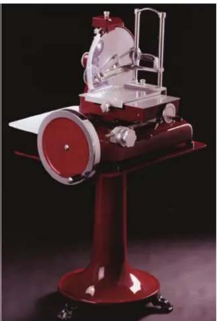
natural_image
Red laboratory instrument with mechanical components and a paper roll on a stand (no visible text or symbols)
Toll Free: 1-800-465-0234
Fax: 905-607-0234
Email: service@omcan.com
www.omcan.com
Table of Contents
Model MS-IT-0250-M / Model MS-IT-0300-M
Model MS-IT-0350-M / Model MS-IT-0370-M
Section Page
General Information 3 - 4
Safety and Warranty 4 - 7
Technical Specifications 7
Installation 7 - 9
Operation 9 - 11
Maintenance 11 - 15
Troubleshooting 15
Instructions Français 16 - 27
Figure Drawings 40 - 45
Parts Breakdown 46 - 92
Notes 93 - 94
Warranty Registration 95
General Information
Omcan Manufacturing and Distributing Company Inc., Food Machinery of America, Inc. dba Omcan and Omcan Inc. are not responsible for any harm or injury caused due to any person's improper or negligent use of this equipment. The product shall only be operated by someone over the age of 18, of sound mind, and not under the influence of any drugs or alcohol, who has been trained in the correct operation of this machine, and is wearing authorized, proper safety clothing. Any modification to the machine voids any warranty, and may cause harm to individuals using the machine or in the vicinity of the machine while in operation.
CHECK PACKAGE UPON ARRIVAL
Upon receipt of an Omcan shipment please inspect for external damage. If no damage is evident on the external packaging, open carton to ensure all ordered items are within the box, and there is no concealed damage to the machine. If the package has suffered rough handling, bumps or damage (visible or concealed), please note it on the bill of lading before accepting the delivery and contact Omcan within 24 hours, so we may initiate a claim with the carrier. A detailed report on the extent of the damage caused to the machine must be filled out within three days, from the delivery date shown in the shipping documents. Omcan has no recourse for damaged products that were shipped collect or third party.
Before operating any equipment, always read and familiarize yourself with all operation and safety instructions.
Omcan would like to thank you for purchasing this machine. It's of the utmost importance to save these instructions for future reference. Also save the original box and packaging for shipping the equipment if servicing or returning of the machine is required.
Check the slicer's mechanical integrity prior to every use. Components should show no signs of damage or cracks. If this is not the case, DO NOT use the slicer and take it to an authorised service centre so that the necessary checks can be performed.
The slicer is not designed for use by people (including children) with physical, sensory or mental
difficulties unless supervised or trained by persons responsible for their safety.
Children and young people should be supervised so that they do not play with the slicer.
The blade is very sharp and should be handled with extreme care.
Do not damage the blade by cutting hard objects such as bones.
Safe use requires compliance with the following warnings:
• Install the machine in accordance with the instructions given under the “Installation” section.
• Install the machine in an area that cannot be accessed untrained people and children.
Use of the machine requires full attention. PAY ATTENTION AT ALL TIMES!
Do not wear loose-fitting clothes particularly with open sleeves; where necessary use suitable headgear to hold back hair.
- When slicing, do not allow anyone to touch the slicer, especially the blade.
- Do not remove, cover or alter the rating plates fitted to the machine body and ensure their prompt replacement in case of damage.
Do not remove safety devices and do not alter or remove safety guards.
- Only approved product types should be sliced, do not attempt to slice products that are specifically excluded.
- Ensure that the product holder, receiving tray, surrounding areas and floor are kept clean and dry at all times.
- Do not use the slicer as a supporting surface or lay any object on it that will not allow normal slicing operations.
- Stop the machine immediately and request the assistance of authorised technical support staff in the event of malfunction, suspected breakage, improper movements, strange noises, etc.
Always use cut and tear-resistant gloves when performing cleaning and maintenance.
The product to be sliced should only be placed on and removed from the feed carriage when the latter is fully retracted (furthest away from the blade) and the carriage nearest the operator.
DO NOT use slicing accessories that have not been supplied by Omcan.
Please contact the Omcan or an authorised service centre for all extraordinary maintenance operations (chain, blade replacement, etc.).
USING THE SLICER CORRECTLY
The slicer is only designed to slice food of the type and size specified herein.
Safety and Warranty
Omcan does not accept liability for improper use or use by staff who have failed to read and fully understand the contents of this manual; do-it-yourself alterations and/or repairs; use of spares that are non-original or not specifically designed for the slicer model covered by this user guide.
The following products may be sliced:
- All types of cold cuts (raw and cooked ham, bacon).
- Boneless meat (cooked or raw at a temperature of not less than +3^ ).
The following products CANNOT be sliced as they are liable to cause serious harm to the user and/or the slicer itself:
- Frozen food.
- Deep-frozen food.
- Food with bones (meat and fish).
- Cheese.
- Any other type of product which is able to be sliced but not intended to be eaten.
Under no circumstances should you attempt to slice any products listed above.
MANUFACTURER'S WARRANTY AND LIABILITY
- The slicer is covered by warranty specified in the enclosed certificate.
- The warranty guarantees that the slicer is of merchantable quality and fit for its intended purpose is subject to correct application of the provisions contained herein.
Omcan shall accept no direct or indirect liability arising from:
- Failure to comply with the instructions given in this manual.
- Use by staff who have failed to read and fully understand the contents of this manual.
- Use that fails to comply with specific current regulations of local law.
• Alterations and/or repairs to the machine performed without prior authorisation. - Use of accessories not supplied by Omcan and non-original spares.
When transferring ownership of the slicer, failure to hand over this guide to the new owner shall automatically exempt Omcan from any liability.
The slicer mentioned in this instruction booklet is designed and manufactured according to current standards with the CE marking confirming such conformity. In particular, the slicer complies with standard EN 1974 (for requirements deemed applicable).
The rating plate is positioned on the base of the slicer as shown in fig.1.
The rating plate should NOT be removed and should remain legible at all times. In the event of damage or wear, the user has a duty to contact Omcan and obtain a replacement.
1 YEAR PARTS AND LABOUR WARRANTY
Safety and Warranty
Within the warranty period, contact Omcan Inc. at 1-800-465-0234 to schedule an Omcan authorized service technician to repair the equipment locally.
Unauthorized maintenance will void the warranty. Warranty covers electrical and part failures, not improper use.
Please see www.omcan.com/warranty.html for complete info.
WARNING:
The packaging components are classified as normal solid urban waste and can therefore be disposed of without difficulty.
In any case, for suitable recycling, we suggest disposing of the products separately (differentiated waste) according to the current norms.
DO NOT DISCARD ANY PACKAGING MATERIALS IN THE ENVIRONMENT!
Technical Specifications
| Model MS-IT-0250-M | MS-IT-0300-M MS-IT | -0350-M MS-IT-0370-M | ||
| Blade Diameter 250 | mm / 9.8" 300mm / 11 | 8" 350mm / 13.8" 370 | mm / 14.6" | |
| Slice Thickness 0-20 | mm / 0-0.8" 0-25mm / 0-1" | |||
| Slicer Weight 33 kg. | / 72.8" 45.3 kg. / 99.8" | 80.8 kg. / 178" | ||
| Stand Weight(Optional) | 71.8 kg. / 158.2" 74.8 kg. / 164.8" | |||
| Item Number 20013 | 13634 13639 18830 | |||
Installation
UNPACKING
When transporting the slicer, ensure that the packaging is fully intact; if this is not the case, please advise the courier or local dealer immediately. In order to remove the slicer from the packaging, please proceed as follows:
- Cut and remove the plastic bands.
- Open the box and take out the instruction booklet.
Installation
• Proceed as described below:
- Remove the protective cardboard covers from inside the box.
- Lift the machine with care and place on a solid surface.
- Remove the plastic bag in which the slicer is wrapped.
- Check that all components and this instruction booklet are present and fully intact.
Should any faults be noted, such as:
• Dents to the frame or guards;
- Controls that are either not working or broken;
- Missing items or other problems;
Please advise the courier, manufacturer and service centre immediately.
Carefully dispose of packaging components (bands, cardboard, polystyrene, polyethylene bags, etc.).
Packaging components (bands, cardboard, polyethylene, etc.) can be treated as municipal solid waste and therefore disposed of without any problem. In any event, it is preferable to sort products prior to disposal in accordance with current recycling regulations.
DO NOT DUMP PACKAGING! DISPOSE OF WASTE RESPONSIBLY!
DESCRIPTION OF THE SLICER
- Slice receiving surface.
- Slice deflector.
- Pusher.
- Sliding product holder.
- Carriage.
- Flywheel operating handle.
- Flywheel.
- Base.
- Blade guard.
- Pusher vertical slide lever.
- Sliding product holder fast forward lever.
- Sliding product holder operating handwheel.
- Slice thickness control graduated knob.
- Blade cover.
- Supporting foot.
- Blade.
- Sharpener and cover.
- Grease collection pan.
- Blade drive chain.
- Bevel gear.
INSTALLING THE SLICER
Position the slicer in its allocated workplace.
Use of stand (optional) (Fig. 4)
If using the optional stand, it should be positioned on the floor whilst checking that it is level and that all three feet are resting correctly on the ground. Carefully lift the slicer and position it on the stand.
Ensure that all slicer feet are resting correctly on top of the stand.
Positioning the slicer (Fig. 5)
If not using the optional stand, carefully lift the slicer and position on a level surface that is dry and capable of supporting the weight of both the slicer and the product to be sliced (see “Technical specifications”).
Ensure that there are no obstructions to the movement of the flywheel, carriage stroke and loading of the product to be sliced.
Ensure that all slicer feet are resting correctly on the work surface.
Operation
DESCRIPTION OF CONTROLS
Flywheel
Clockwise rotation of the flywheel (Fig. 2, #7) using the handle (Fig. 2, #6) will move the carriage (Fig. 2, #5) with product holder (Fig. 2, #4), while turning the blade (Fig. 2, #16) at the same time.
Slice thickness control knob
Turn the knob (Fig. 2, #13) clockwise in order to obtain a thicker slice or counterclockwise for a thinner one. The knob (Fig. 2, #13) has a graduated scale ranging from "0" to "8" (thickness 2 mm).
Sliding product holder operating handwheel
The handwheel (Fig. 2, #12) allows you move the product holder (Fig. 2, #4) towards or away from the blade (Fig. 2, #16).
It can also be used to make slight movements of the product holder (Fig. 2, #4).
Sliding product holder faster with lever
By lowering and holding in position the lever (Fig. 11, #11) you can quickly move the product holder (Fig. 11, #4) towards or away from the blade (Fig. 11, #16) (with product).
The operation is quicker than when using the handwheel (Fig. 11, #12).
Operation
Pusher vertical slide lever
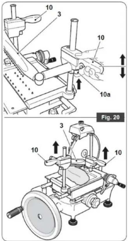
By keeping pressed the lower button (Fig. 11, #10a) for the vertical slide lever (Fig. 11, #10) you can quickly raise or lower the pusher (Fig. 11, #3).
USING THE SLICER
WARNING:
- DO NOT use the slicer if not fully physically and mentally capable.
- DO NOT allow anyone to come near or touch the slicer while in operation.
- Be extremely careful when loading/unloading the product from the product holder and when slicing.
PAY ATTENTION AT ALL TIMES!
PLACING PRODUCT ON PRODUCT HOLDER
- Turn the flywheel (Fig. 12, #7) in order to move the carriage (Fig. 12, #5) to its forward limit (towards the operator).
- Move the product holder (Fig. 13, #4) the farthest it can go from the blade using either the handwheel (Fig. 13, #12) or the fast forward lever (Fig. 13, #11).
- Position the product to be sliced on the product holder (Fig. 14a, #4) and hold in place with the pusher (Fig. 14a, #3) (so that it is fixed), whilst adjusting the height.
Failure to hold the product firmly in place on the product holder could cause the machine to cut uneven slices.
- Turn the knob (Fig. 14b, #13) in order to set the required slice thickness.
- Bring the product holder (Fig. 15, #4) (with the product) back from its limit of travel (towards the blade) using either the handwheel (Fig. 15, #12) or the fast forward lever (Fig. 15, #11).
Draw the product holder (Fig. 15, #4) closer to the blade leaving a space between the product to be sliced and the blade of 0.5 cm to 1.0 cm.
SLICING THE PRODUCT
- Move the blade guard (Fig. 16, #9) away from its seat by loosening the knob (Fig. 16, #9a) lifting up and placing on the flange away from the blade, remember to tighten the knob after moving the guard.
WARNING:
Exercise great caution if the blade guard (Fig. 16, #9) is not fitted; the blade (Fig. 16, #16) is extremely sharp.
- Hold the handle (Fig. 17, #6) and turn the flywheel (Fig. 17, #7) clockwise in order to begin blade rotation and the alternating movement of the product holder (Fig. 17, #4).
DO NOT turn the flywheel (Fig. 2, #7) counterclockwise. Serious damage to the slicer could be caused.
- Turn the flywheel (Fig. 2, #7) 4 to 5 times so the product touches the blade (Fig. 2, #16).
- While the carriage (Fig. 2, #5) moves forward (away from the operator), the blade (Fig. 2, #16) enters the product. Guided by the deflector (Fig. 2, #2), a slice is cut and drops onto the slice receiving surface (Fig. 2, #1).
- As the carriage (Fig. 2, #5) returns (towards the operator), the product holder (Fig. 2, #4) moves sideways towards the blade (Fig. 2, #16). The amount of sideways movement is set by using the slice thickness control knob (Fig. 2, #13).
- Stop turning the flywheel (7) once the operation is complete; the blade will stop its movement (16).
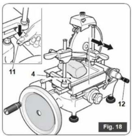
- Move the product holder (Fig. 2, #4) (with the remaining product) away from the blade (Fig. 2, #16) using either the handwheel (Fig. 18, #12) or the fast forward lever (Fig. 18, #11).
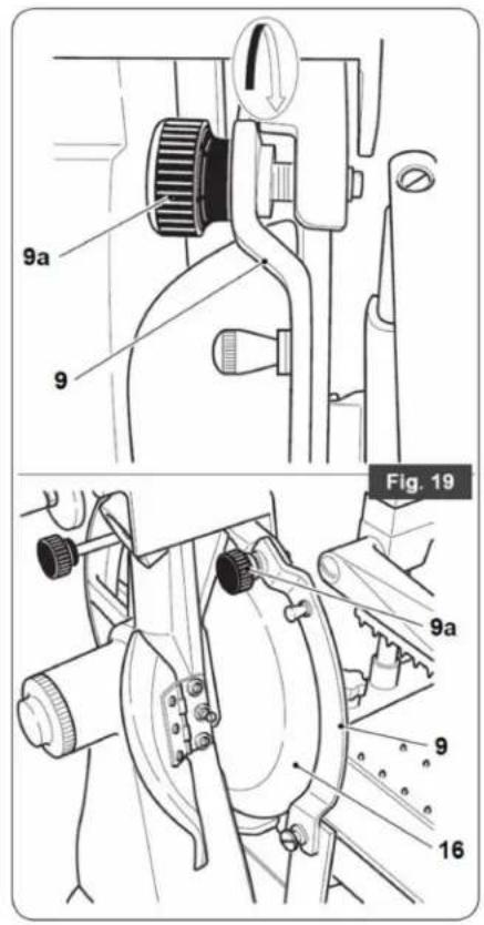
- Reposition the blade guard (Fig. 13, #9) by tightening the knob (Fig. 13, #9a).
WARNING:
Do not leave the slicer without the blade guard (Fig. 19, #9) in the correct position. This is hazardous to the operator!
- Press the two buttons (Fig. 20, #10a) while lifting the pusher (Fig. 20, #3).
- Remove the product from the table (Fig. 2, #4).
- Clean the slicer as described in the "Maintenance" section.
Maintenance
CLEANING THE SLICER
The slicer MUST be cleaned thoroughly at least once a day and more frequently where necessary. Clean the slicer before use of it or if it has been out of service for a prolonged period of time.
WARNING: Cutting hazard! Use protective cut- and tear-resistant gloves and perform all operations with extreme care. PAY ATTENTION AT ALL TIMES!
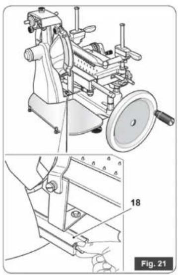
- Remove the receiving tray (Fig. 21, #18).
- Unscrew knob (Fig. 22, #34) and lift the sliding product holder (Fig. 22, #4) complete with pusher arm (Fig. 22, #3).
- Clean all dismantled parts and the machine body just hot water (at a temperature of not less than 30^ C) and a frothy biodegradable dishwasher detergent. Use a soft spongy cloth and, if necessary, a nylon brush for the spiked areas of the product holder (Fig. 2, #4) and pusher (Fig. 2, #3).
- Rinse in hot water only and dry with soft spongy cloths.
WARNING: DO NOT clean the machine with water jets, steam or similar methods or in dishwashers using corrosive detergents.
The base (Fig. 2, #8) and painted parts can be cleaned with a soft cloth avoiding the use of abrasive
Maintenance
detergents.
- Reposition the product holder (Fig. 22, #4) ensuring that the catch (Fig. 23, #35) engages the carriage (Fig. 23, #5).
- Secure the product holder (Fig. 23, #4) to the carriage (Fig. 23, #5) by tightening the knob (Fig. 23, #34).
CLEANING THE BLADE
WARNING: Cutting hazard! Use protective cut- and tear-resistant gloves and perform all operations with extreme care. PAY ATTENTION AT ALL TIMES!
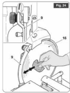
- Press a damp cloth on the blade (Fig. 24, #16) and rub slowly moving from inside to out.
WARNING: ALWAYS clean the blade (Fig. 24, #16) with the blade guard (Fig. 24, #9) fitted behind it in the safety position.
CLEANING THE BLADE COVER
WARNING: Cutting hazard! Use protective cut- and tear-resistant gloves and perform all operations with extreme care. PAY ATTENTION AT ALL TIMES!
- Damp a cloth in a solution of water and alcohol.
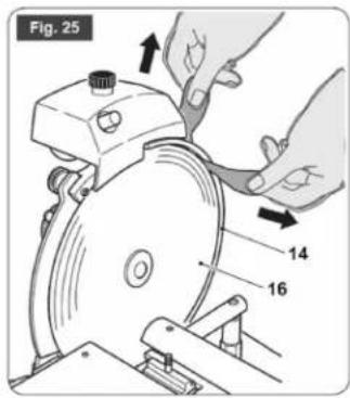
- Place the damp cloth between the blade cover (Fig. 25, #14) and blade (Fig. 25, #16).
• Take the two ends of the cloth between your hands and slide it along the blade cover (Fig. 25, #14).
WARNING: ALWAYS clean the blade (Fig. 2, #16) with the blade guard (Fig. 2, #9) fitted.
Do not use detergents to clean the blade (Fig. 2, #16).
CLEANING THE SLICE RECEIVING SURFACE
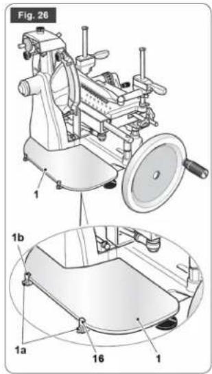
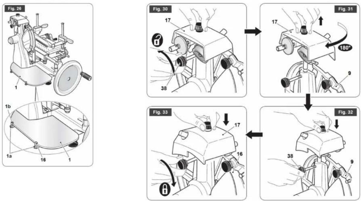
- Remove the slice receiving surface (Fig. 26, #1) by loosening the two screws (Fig. 26, #1a) and releasing from the retaining clips (Fig. 26, #1b).
- Wash the tray with water and normal dishwasher detergent).
ROUTINE MAINTENANCE
In addition to the above-mentioned cleaning operations, you should also perform routine maintenance in order to guarantee the slicer's operating efficiency over time. The operator may perform the following maintenance operations:
- Oiling carriage guide rail (Fig. 2, #5) and product holder (Fig. 2, #4) and lubrication points.
- Frequency: Weekly.
- Oiling chain (Fig. 2, #19) and bevel gear (Fig. 2, #20).
- Frequency: Every 6 months.
- Blade sharpening
Sharpen the blade (Fig. 2, #16) periodically or at least once every 6 months.
How often sharpening is necessary and how long it lasts depend on the type of use to which the slicer is put (operating times and processed product).
Being particularly complicated and hazardous for the operator, other maintenance operations SHOULD only be performed by staff from an authorised service centre.
These operations are:
- Blade replacement.
- Sharpener grinding wheel replacement.
- Chain replacement.
• Repair of structural parts, repair and/or replacement of components located beneath the base.
OILING CARRIAGE GUIDE RAIL AND PRODUCT HOLDER AND LUBRICATION POINTS
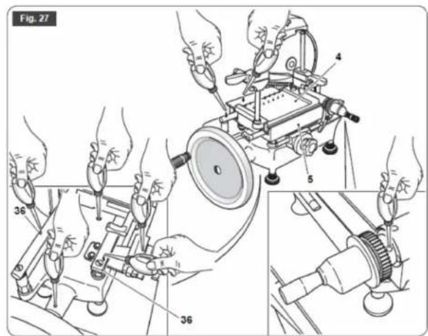
- Every week you should oil the carriage (Fig. 27, #5) and product holder (Fig. 27, #4) guide rails (Fig. 27, #36) using the supplied lubricant.
- Also oil the points indicated in figure 27.
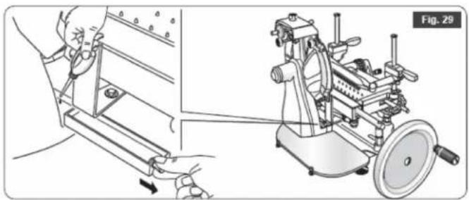
- Remove the grease collection pan (Fig. 2, #18) and oil the nozzle (figure 29).
If you run out of the supplied lubricant, use White Mineral Oil provided by Omcan (Item No. 39115).
Do not use vegetable oil.
- Apply a few drops of lubricant (maximum 3 or 4) to the guide rails and slide the assemblies back and forth 3/4 times.
- Apply 2/3 drops of lubricant to the lubrication points.
Use the lubricant sparingly.
- Wipe excess lubricant with a paper towel.
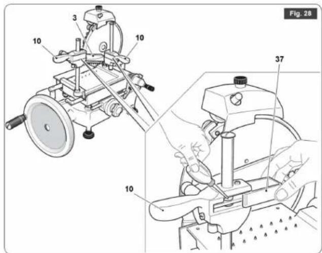
- Also oil the catches (Fig. 28, #10) of the pusher's (Fig. 28, #3) vertically sliding levers.
- Remove the spring-loaded guard (Fig. 28, #37).
- Apply 2/3 drops of lubricant.
- Slide the pusher (Fig. 28, #3) back and forth 3/4 times.
- Wipe excess lubricant with a paper towel.
BLADE SHARPENING
WARNING: Cutting hazard - Use protective cut- and tear-resistant gloves and perform all operations with extreme care. PAY ATTENTION AT ALL TIMES!
WARNING: ALWAYS work with the blade guard (Fig. 2, #9) fitted properly.
Maintenance
Proceed as follows:
- Loosen the knob (Fig. 30, #38) while holding the sharpener (Fig. 30, #17) in place.
- Lift the sharpener (Fig. 31, #17) and turn it 180^ .
- Carefully lower the sharpener (Fig. 32, #17) again, the blade (Fig. 32, #16) will automatically be centred between the two grinding wheels.
- Tighten the knob (Fig. 33, #38).
- Turn the flywheel (Fig. 2, #7) while pressing the "X" button and perform about 20 to 30 blade revolutions.
- Stop rotating and check that a slight burr has formed on the blade edge.
- Turn the flywheel (Fig. 2, #7) again while pressing the "K" button and perform 1 or 2 blade revolutions.
For safety reasons do not exceed 1 or 2 blade revolutions in order to prevent the blade edge from springing back.
- Return the sharpener to its original position.
OILING THE CHAIN AND GEAR
Every 6 months proceed as follows:
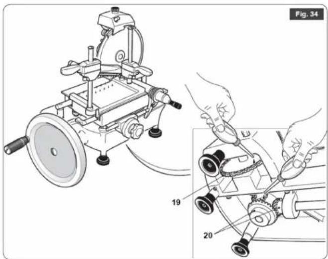
- Lift the slicer and apply 3 to 4 drops of the supplied lubricant to the chain (Fig. 2, #19) and gears (Fig. 2, #20).
If you run out of the supplied lubricant, use White Mineral Oil provided by Omcan (Item No. 39115).
Do not use vegetable oil.
Use the lubricant lightly.
- Wipe excess lubricant with a paper towel.
TAKING THE SLICER OUT OF SERVICE
A machine comprises:
- Aluminium-alloy frame.
- Stainless-steel inserts and components.
- Plastics.
When commissioning third parties to perform dismantling and demolition, only businesses authorised to dispose of these materials should be employed.
When demolishing without outside assistance, sort the various types of material and hand over to authorised businesses for disposal.
ALWAYS comply with the current legislation of the country in which the slicer is used.
WARNING: ALWAYS consult Omcan as regards to removal and disposal of the blade (Fig. 2, #16) so that disposal can take place in complete safety.
DO NOT DUMP SCRAP COMPONENTS AS THEY REPRESENT A SERIOUS ENVIRONMENTAL HAZARDS, PARTICULARLY FOR CHILDREN AND ANIMALS.
Troubleshooting
| PROBLEM PROBABLE | CAUSE SOLUTION | |
| Difficulty in slicing; excessive resistance when the product is in contact with the blade. | The blade is blunt. Sharpen the blade. | |
| Slices are of irregular thickness. The | pusher fails to retain the product correctly. | Reposition the pusher in order to retain the product correctly. |
| The blade is blunt. Sharpen the blade. | ||
| Slices come out as “doorsteps”. The | pusher fails to retain the product correctly. | Reposition the pusher in order to retain the product correctly. |
| The blade is blunt. Sharpen the blade. | ||
| Slices are empty in the middle. The | product is too soft (not mature enough). | Press the pusher harder. |
| The blade is blunt. Sharpen the blade. | ||
| Slices disintegrate into several pieces; they are not sliced cleanly. | Worn blade. Replace the blade. |
REFERENCE
| Item Number | Model Number D | Description Manufacturer Model Number | |
| 20013 MS- | IT-0250-M | Meat Slicer Manual Volano 10” / 250mm Blade CE ETL Sanitation | 250VO |
| 13634 MS- | IT-0300-M | Meat Slicer Manual Volano 12” / 300mm Blade CE ETL Sanitation | 300VO |
| 13639 MS- | IT-0350-M | Meat Slicer Manual Volano 14” / 350mm Blade CE ETL Sanitation | 350VO |
| 18830 MS- | IT-0370-M | Meat Slicer Manual Volano 15” / 370mm Blade CE ETL Sanitation | 370VO |
Instructions Français
SÉCURITÉ ET GARANTIE
AVERTISSEMENTS UTILISATEUR
TRANCHAGE LE PRODUIT
Fig. 2
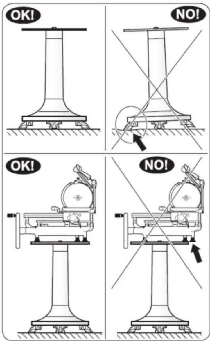
Fig. 4
Figure Drawings
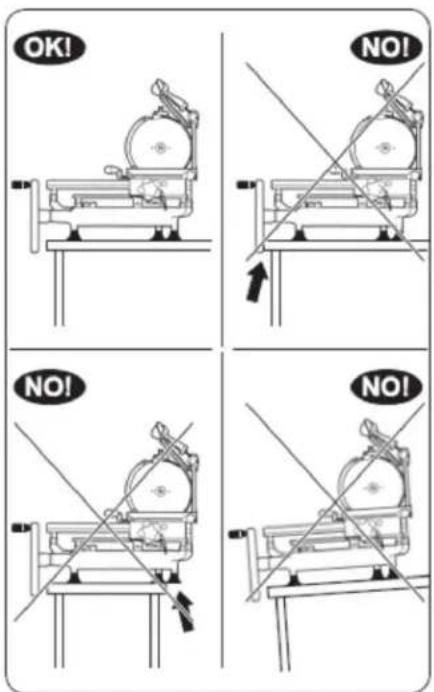
Fig. 5
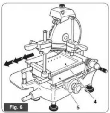
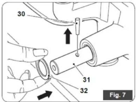
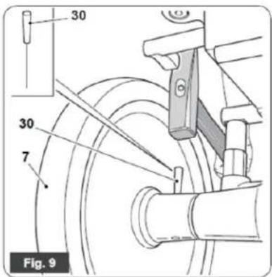
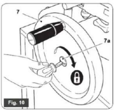
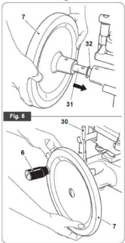
Fig. 11
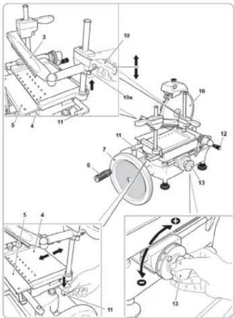
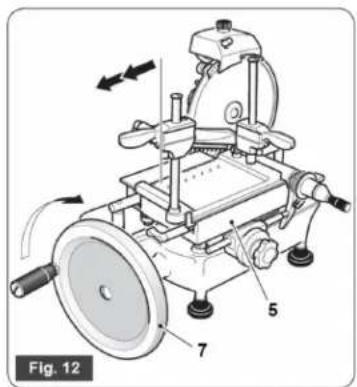
Figure Drawings
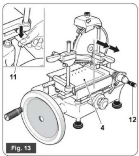
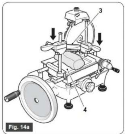
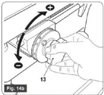
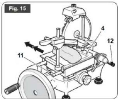
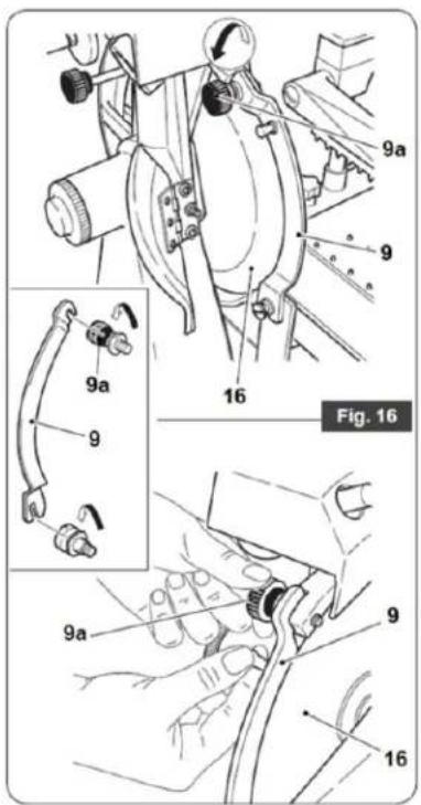
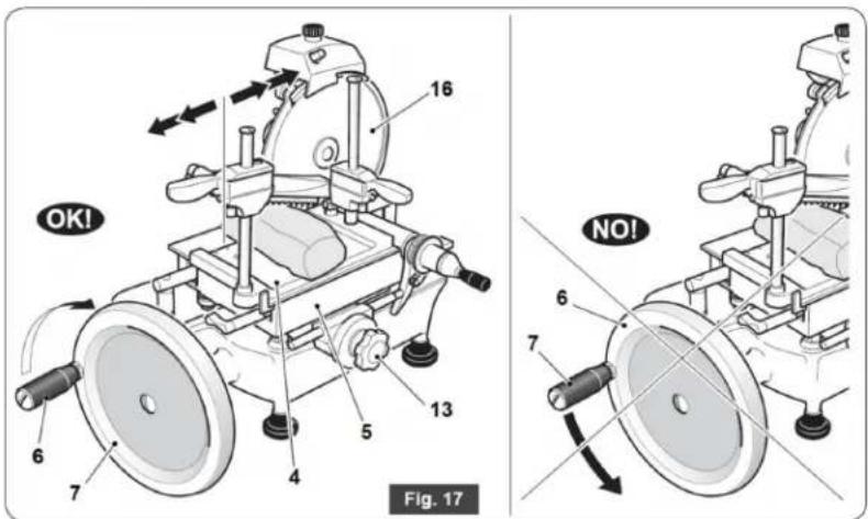
Figure Drawings
natural_image
Technical illustration of a mechanical device with a close-up view showing a hand operating a workbench (no text or symbols present)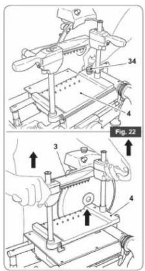
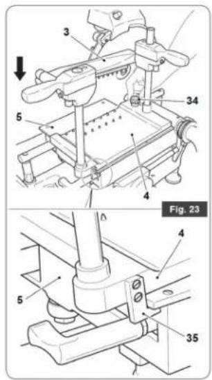
Figure Drawings
natural_image
Technical illustration of a mechanical device with hands operating it, showing assembly and maintenance (no text or symbols)Figure Drawings
natural_image
Technical illustration of a mechanical device with labeled parts, showing assembly and disassembly (no text or symbols present)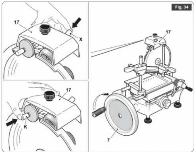
Parts Breakdown
Model MS-IT-0250-M 20013 Base

Parts Breakdown
Model MS-IT-0250-M 20013
Cart Guide
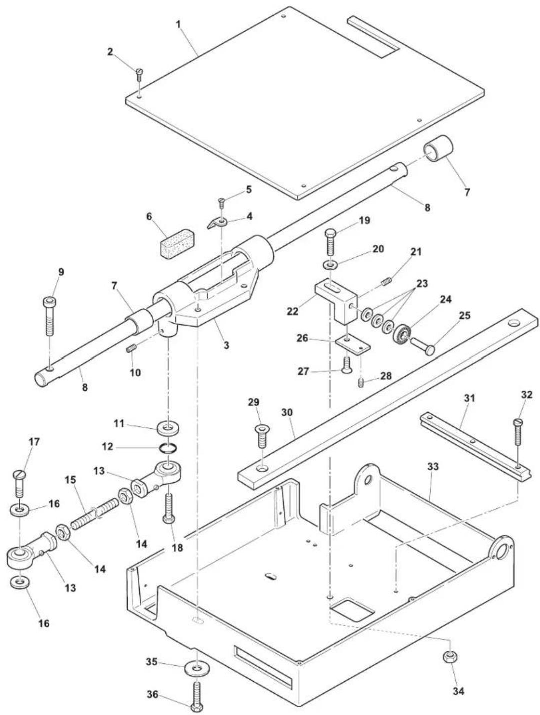
Parts Breakdown
Model MS-IT-0250-M 20013
Blade Assembly
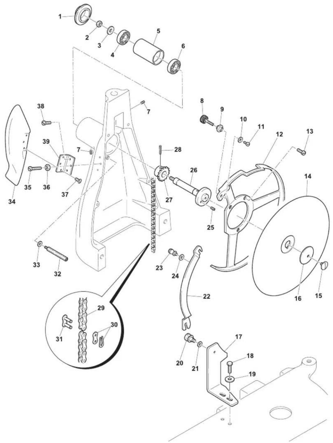
Parts Breakdown
Model MS-IT-0250-M 20013 Cart

Parts Breakdown
Model MS-IT-0250-M 20013 Thickness Adjustor
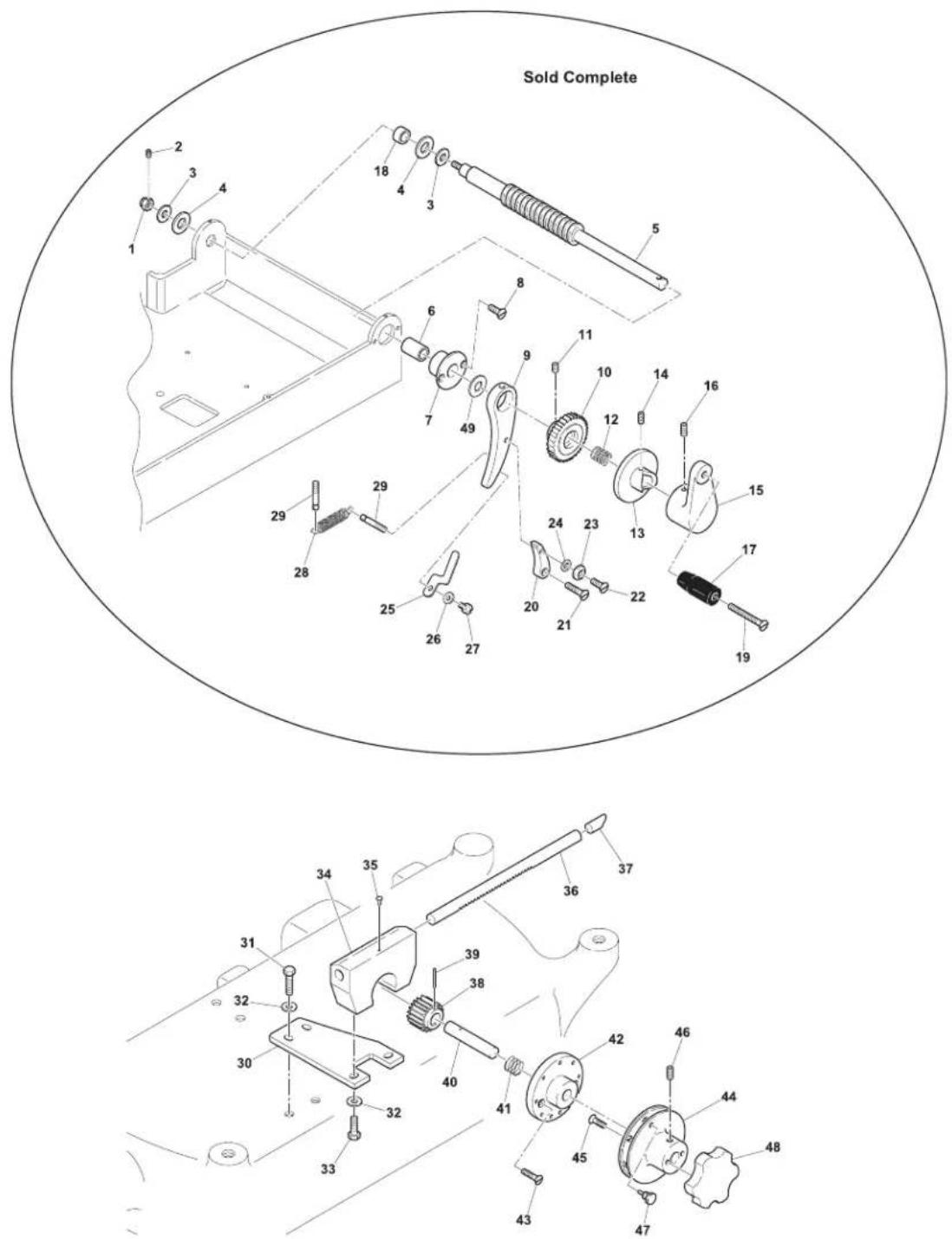
Model MS-IT-0250-M 20013 Fly Wheel
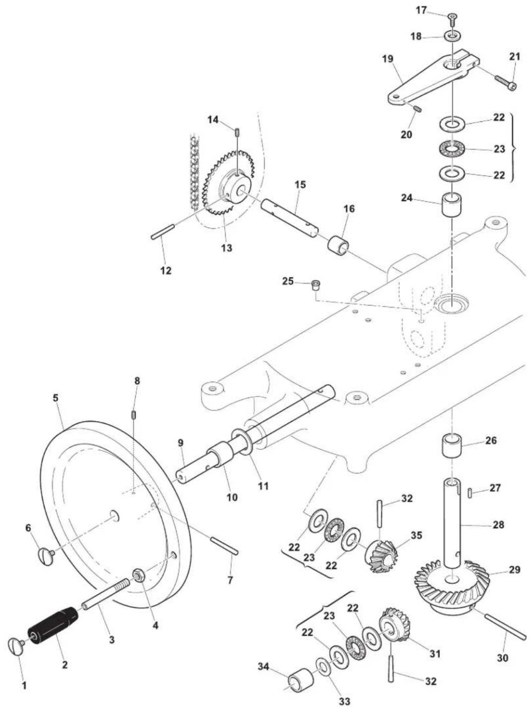
Parts Breakdown
Model MS-IT-0250-M 20013 Meat Tray Assembly
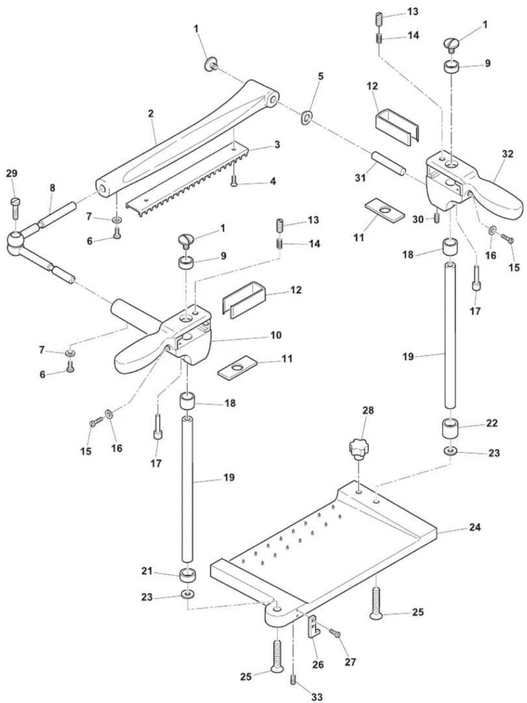
Model MS-IT-0250-M 20013 Sharpening Assembly
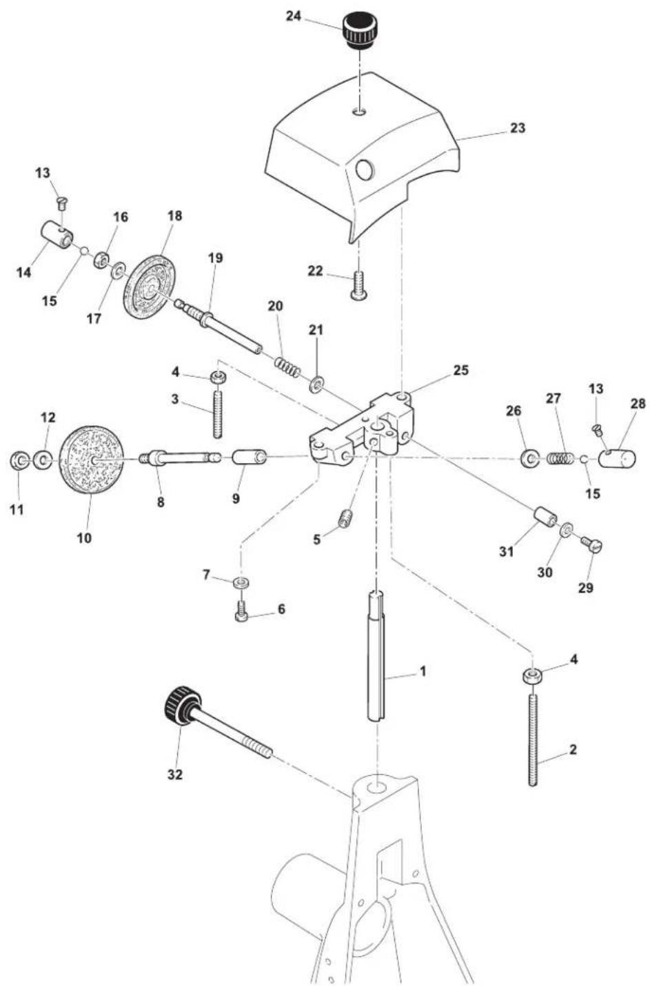
Parts Breakdown
Model MS-IT-0250-M 20013 Base
Item No. Description Position Item No. Description P
| 32771 Housing for 250VO 1 32780 Tray Support Bar for 250VO 10 32789 | ||
| 32772 | Foot for 250VO | 2 |
| 32773 | Slide Bar Support for 250VO | 3 |
| 32774 | Thumb Screw for 250VO | 4 |
| 32775 | Washer for 250VO | 5 |
| 32776 | Plate Stop for 250VO | 6 |
| 32777 | Tray Support Bar for 250VO | 7 |
| 32778 | Pin for 250VO | 8 |
32779 Tray for 250VO
position Item No. Description Position
| Nut for 250VO | 19 | |
| 32781 | Blade Assembly Casing for 250VO | 11 |
| 32782 | Chain Guard for 250VO | 12 |
| 32783 | Washer for 250VO | 13 |
| 32784 | Screw for 250VO | 14 |
| 32785 | Foot for 250VO | 15 |
| 32786 | Tray for 250VO | 16 |
| 32787 | Thumb Screw for 250VO | 17 |
9 32788 Washer for 250VO
18
| 32790 | Pin for 250VO | 20 |
| 32791 | Slide Bar Support for 250VO | 21 |
| 32792 | Washer for 250VO | 22 |
| 32793 | Nut for 250VO | 23 |
| 32794 | Washer for 250VO | 24 |
| 32795 | Pin for 250VO | 25 |
| 32796 | Pin for 250VO | 26 |
Cart Guide
Item No. Description Position Item No. Description P
| 32797 | Bottom Plate for 250VO | 1 |
| 32798 | Screw for 250VO | 2 |
| 32799 | Carriage Support for 250VO | 3 |
| 32800 | Bracket for 250VO | 4 |
| 32801 | Screw for 250VO | 5 |
| 32802 | Wick for 250VO | 6 |
| 32803 | Slide Bar Bushing for 250VO | 7 |
| 32804 | Carriage Slide Bar for 250VO | 8 |
| 32805 | Screw for 250VO | 9 |
| 32806 | Set Screw for 250VO | 10 |
| 32807 | Washer for 250VO | 11 |
| 32808 | Washer for 250VO | 12 |
position Item No. Description Position
| 32809 | Joint for 250VO | 13 |
| 32810 | Nut for 250VO | 14 |
| 32811 | Pin for 250VO | 15 |
| 32812 | Washer for 250VO | 16 |
| 32813 | Screw for 250VO | 17 |
| 32814 | Screw for 250VO | 18 |
| 32815 | Screw for 250VO | 19 |
| 32816 | Washer for 250VO | 20 |
| 32817 | Set Screw for 250VO | 21 |
| 32818 | Sharpener Support Bracket for 250VO | 22 |
| 32819 | Washer for 250VO | 23 |
| 32820 | Bearing for 250VO | 24 |
| 32821 | Bearing Pin for 250VO | 25 |
| 32822 | Tab for 250VO | 26 |
| 32823 | Screw for 250VO | 27 |
| 32824 | Set Screw for 250VO | 28 |
| 32825 | Screw for 250VO | 29 |
| 32826 | Carriage Rail for 250VO | 30 |
| 32827 | Slide Bar for 250VO | 31 |
| 32828 | Screw for 250VO | 32 |
| 32829 | Plate Base for 250VO | 33 |
| 32830 | Nut for 250VO | 34 |
| 32831 | Washer for 250VO | 35 |
| 32832 | Screw for 250VO | 36 |
Model MS-IT-0250-M 20013
Blade Assembly
| Item No. | Description Position | Item No. | Description P |
| 32833 | Blade Shaft Cap for 250VO | 1 | |
| 32834 | Nut for 250VO | 2 | |
| 32835 | Washer for 250VO | 3 | |
| 32836 | Bearing for 250VO | 4 | |
| 32837 | Sleeve for 250VO | 5 | |
| 32838 | Bearing for 250VO | 6 | |
| 32839 | Set Screw for 250VO | 7 | |
| 32840 | Thumb Screw for 250VO | 8 | |
| 32841 | Spacer for 250VO | 9 | |
| 32842 | Washer for 250VO | 10 | |
| 32843 | Screw for 250VO | 11 | |
| 32844 | Safety Guard Ring for 250VO | 12 | |
| 32845 | Screw for 250VO | 13 |
| Position Item No. Description Position | ||
| 24039 | Blade for 250VO | 14 |
| 32847 | Screw Chrome for 250VO | 15 |
| 32848 | Washer for 250VO | 16 |
| 32849 | Bracket for 250VO | 17 |
| 32850 | Screw for 250VO | 18 |
| 32851 | Washer for 250VO | 19 |
| 32852 | Thumb Screw for 250VO | 20 |
| 32853 | Washer for 250VO | 21 |
| 32854 | Blade Guard for 250VO | 22 |
| 32855 | Screw for 250VO | 23 |
| 32856 | Washer for 250VO | 24 |
| 32857 | Set Screw for 250VO | 25 |
| 32858 | Bearing and Shaft for 250VO | 26 |
| 32859 | Pinion for 250VO | 27 |
| 32860 | Pin for 250VO | 28 |
| 32861 | Chain for 250VO | 29 |
| 32862 | Chain Link for 250VO | 30 |
| 32863 | Chain Link for 250VO | 31 |
| 32864 | Guide Rod for 250VO | 32 |
| 32865 | Washer for 250VO | 33 |
| 32866 | Meat Deflector for 250VO | 34 |
| 32867 | Screw for 250VO | 35 |
| 31315 | Nut for 250VO | 36 |
| 31314 | Screw for 250VO | 37 |
| 32868 | Screw for 250VO | 38 |
| 31325 | Hinge for 250VO | 39 |
Cart
| Item No. | Description | Position Item No. | Description P |
| 32869 | Comb Block for 250VO | 1 32881 Pin for 250VO | 13 32893 Pin for 25 |
| 32870 | Screw for 250VO | 2 | |
| 32871 | Sharpener Support Bracket for 250VO | 3 | |
| 32872 | Support Mount for 250VO | 4 | |
| 32873 | Pivot Rod for 250VO | 5 | |
| 32874 | Screw for 250VO | 6 | |
| 32875 | Spring for 250VO | 7 | |
| 32876 | Screw for 250VO | 8 | |
| 32877 | Washer for 250VO | 9 | |
| 32878 | Nut for 250VO | 10 | |
| 32879 | Pin for 250VO | 11 |
| Position Item No. Description Position | ||
| 0VO 25 | ||
| 32882 | Socket Head Screw for 250VO | 14 |
| 32883 | Pin for 250VO | 15 |
| 32884 | Nut for 250VO | 16 |
| 32885 | Screw for 250VO | 17 |
| 32886 | Moving Plate for 250VO | 18 |
| 32887 | Side Plate for 250VO | 19 |
| 32888 | Leveler for 250VO | 20 |
| 32889 | Nut for 250VO | 21 |
| 32890 | Bushing for 250VO | 22 |
| 32891 | Clip for 250VO | 23 |
| 32894 | Needle Rod for 250VO | 26 |
| 32895 | Screw for 250VO | 27 |
| 32896 | Washer for 250VO | 28 |
| 32897 | Tab for 250VO | 29 |
| 32898 | Nut for 250VO | 30 |
| 32899 | Spring for 250VO | 31 |
| 32900 | Washer for 250VO | 32 |
| 32901 | Socket Head Screw for 250VO | 33 |
| 32902 | Slide Bar Cover for 250VO | 34 |
| 32903 | Bottom Plate Cover for 250VO | 35 |
32880 Mount for 250VO 12 32892 Pin for 250VO 24
Parts Breakdown
Model MS-IT-0250-M 20013 Thickness Adjustor
Item No. Description Position Item No. Description P
| 32904 Acorn Nut for 250VO 1 32921 Feed Screw Bushing for 250VO 18 3 | ||
| 32905 | Set Screw for 250VO | 2 |
| 32906 | Washer for 250VO | 3 |
| 32907 Washer for 250VO | 4 32924 Screw for 250VO | |
| 32908 | Feed Screw Shaft for 250VO | 5 |
| 32909 | Bushing for 250VO | 6 |
| 32910 | Feed Pin Bushing for 250VO | 7 |
| 32911 | Screw for 250VO | 8 |
| 32912 | Big Skip Latch for 250VO | 9 |
| 32913 | Gear for 250VO | 10 |
| 32914 | Set Screw for 250VO | 11 |
| 32915 | Spring for 250VO | 12 |
| 32916 | Wheel Plate for 250VO | 13 |
| 32917 | Set Screw for 250VO | 14 |
| 32918 | Feed Plate Handle Mount for 250VO | 15 |
| 32919 | Set Screw for 250VO | 16 |
| 32920 | Handle for 250VO | 17 |
position Item No. Description Position
| 2938 Rivet for 250VO 35 | ||
| 32922 | Screw for 250VO | 19 |
| 32923 | Small Skip Latch for 250VO | 20 |
| VO 21 32941 Gear for 250VO 38 | ||
| 32925 | Screw for 250VO | 22 |
| 32926 | Nut for 250VO | 23 |
| 32927 | Washer for 250VO | 24 |
| 32928 | Small Spring for 250VO | 25 |
| 32929 | Washer for 250VO | 26 |
| 32930 | Screw for 250VO | 27 |
| 32931 | Spring for 250VO | 28 |
| 32932 | Pin for 250VO | 29 |
| 32933 | Mounting Plate for 250VO | 30 |
| 32934 | Bolt for 250VO | 31 |
| 32935 | Washer for 250VO | 32 |
| 32936 | Screw for 250VO | 33 |
| 32937 | Index Mount for 250VO | 34 |
| 32939 | Fly Rod for 250VO | 36 |
| 32940 | Rod PVC for 250VO | 37 |
| 32942 | Pin for 250VO | 39 |
| 32943 | Steel Pin for 250VO | 40 |
| 32944 | Spring for 250VO | 41 |
| 32945 | Nut for 250VO | 42 |
| 32946 | Screw for 250VO | 43 |
| 32947 | Graduated Scale for 250VO | 44 |
| 32948 | Screw for 250VO | 45 |
| 32949 | Set Screw for 250VO | 46 |
| 32950 | Thumb Screw for 250VO | 47 |
| 32951 | Adjustment Knob for 250VO | 48 |
| 37563 | Washer for 250VO | 49 |
| 31317 | Complete Assembly for 250VO | 1 - 29, 49 |
Fly Wheel
Item No. Description Position Item No. Description P
| 31321 | Screw for 250VO | 1 |
| 31320 | Knob for 250VO | 2 |
| 32952 | Fly Wheel Handle Shaft for 250VO | 3 |
| 32953 | Nut for 250VO | 4 |
| 32954 Fly Wheel for 250VO 5 32966 Screw for 250VO 17 32978 Pin for 2 | ||
| 32955 | Screw Chrome for 250VO | 6 |
| 32956 | Pin for 250VO | 7 |
| 32957 | Set Screw for 250VO | 8 |
| 32958 | Gear Shaft for 250VO | 9 |
| 32959 | Brass Bushing for 250VO | 10 |
| 32960 | Washer for 250VO | 11 |
| 32961 | Pin for 250VO | 12 |
position Item No. Description Position
| 32962 | Pinion for 250VO | 13 |
| 32963 | Set Screw for 250VO | 14 |
| 32964 | Gear Shaft for 250VO | 15 |
| 32965 | Brass Bushing for 250VO | 16 |
| 0VO | 30 | |
| 32967 | Washer for 250VO | 18 |
| 32968 | Support Mount for 250VO | 19 |
| 32969 | Set Screw for 250VO | 20 |
| 32970 | Socket Head Screw for 250VO | 21 |
| 32971 | Axial Bearing for 250VO | 22 - 23 |
| 32972 | Brass Bushing for 250VO | 24 |
| 32973 | Oiler for 250VO | 25 |
| 32974 | Brass Bushing for 250VO | 26 |
| 32975 | Set Screw for 250VO | 27 |
| 32976 | Gear Pivot for 250VO | 28 |
| 32977 | Gear for 250VO | 29 |
| 32979 | Gear for 250VO | 31 |
| 32980 | Pin for 250VO | 32 |
| 32981 | Washer for 250VO | 33 |
| 32982 | Brass Bushing for 250VO | 34 |
| 32983 | Gear for 250VO | 35 |
Model MS-IT-0250-M 20013 Meat Tray Assembly
| Item No. | Description Position | Item No. | Description P |
| 32984 | Screw Chrome for 250VO | 1 | |
| 32985 | Meat Grip Holder for 250VO | 2 | |
| 32986 | Meat Grip Bar for 250VO | 3 | |
| 32987 | Screw TPSV for 250VO | 4 | |
| 32988 | Wavy Washer for 250VO | 5 | |
| 32989 | Screw TC for 250VO | 6 | |
| 32990 | Washer for 250VO | 7 | |
| 32991 | Joint for 250VO | 8 | |
| 32992 | Bar Bushing for 250VO | 9 | |
| 32993 | Handle for 250VO | 10 | |
| 32994 | Brake Tab for 250VO | 11 |
| Position Item No. Description Position | ||
| 32995 | U-Bracket for 250VO | 12 |
| 32996 | Set Screw for 250VO | 13 |
| 32997 | Set Screw for 250VO | 14 |
| 32998 | Screw TC for 250VO | 15 |
| 32999 | Washer for 250VO | 16 |
| 33000 | Socket Head Screw for 250VO | 17 |
| 33001 | Bar Bushing for 250VO | 18 |
| 33002 | Cam for 250VO | 19 |
| 33003 | Spacer for 250VO | 21 |
| 33004 | Spacer for 250VO | 22 |
| 33005 | Washer for 250VO | 23 |
| 31319 | Upper Plate for 250VO | 24 |
| 33006 | Screw TPSV for 250VO | 25 |
| 33007 | Plate Lock for 250VO | 26 |
| 33008 | Screw TC for 250VO | 27 |
| 33009 | Tightening Knob for 250VO | 28 |
| 33010 | Screw TC for 250VO | 29 |
| 33011 | Set Screw for 250VO | 30 |
| 33012 | Steel Pin for 250VO | 31 |
| 33013 | Handle for 250VO | 32 |
| 33014 | Set Screw for 250VO | 33 |
Sharpening Assembly
| Item No. | Description Position Item No. | Description P |
| 33015 | Shaft for Sharpener for 250VO | 1 |
| 33016 | Pin for 250VO | 2 |
| 33017 | Pin for 250VO | 3 |
| 33018 | Nut 5 for 250VO | 4 |
| 33019 | Set Screw 6 X 8 for 250VO | 5 |
| 33020 | Screw TC 4 X 16 for 250VO | 6 |
| 33021 | Washer 5 for 250VO | 7 |
| 33022 | Sharpener Pin for 250VO | 8 |
| 33023 | Pin Bushing for 250VO | 9 |
| 18016 | Grinding Stone for 250VO | 10 |
| 33025 | Nut 6 for 250VO | 11 |
| position Item No. Description Position | ||
| 33026 | Washer for 250VO | 12 |
| 33027 | Push Button Screw for 250VO | 13 |
| 33028 | Sharpener Push Button for 250VO | 14 |
| 33029 | Ball Bearing for 250VO | 15 |
| 33030 | Nut for 250VO | 16 |
| 33031 | Washer for 250VO | 17 |
| 33545 | Finishing Stone for 250VO | 18 |
| 33033 | Sharpener Pin for 250VO | 19 |
| 33034 | Spring for 250VO | 20 |
| 33035 | Washer for 250VO | 21 |
| 33036 | Screw TPSV for 250VO | 22 |
| 33037 | Sharpener Cover for 250VO | 23 |
| 33038 | Sharpener Cover Knob for 250VO | 24 |
| 33039 | Sharpener Body for 250VO | 25 |
| 33040 | Washer for 250VO | 26 |
| 33041 | Spring for 250VO | 27 |
| 33042 | Sharpener Push Button for 250VO | 28 |
| 33043 | Screw TC for 250VO | 29 |
| 33044 | Washer for 250VO | 30 |
| 33045 | Pin Bushing for 250VO | 31 |
| 33046 | Thumb Screw for 250VO | 32 |
Parts Breakdown
Model MS-IT-0300-M 13634 Base
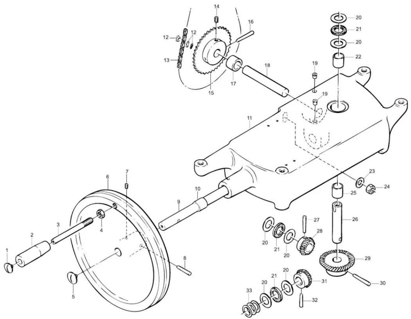
Parts Breakdown
Model MS-IT-0300-M 13634 Guide
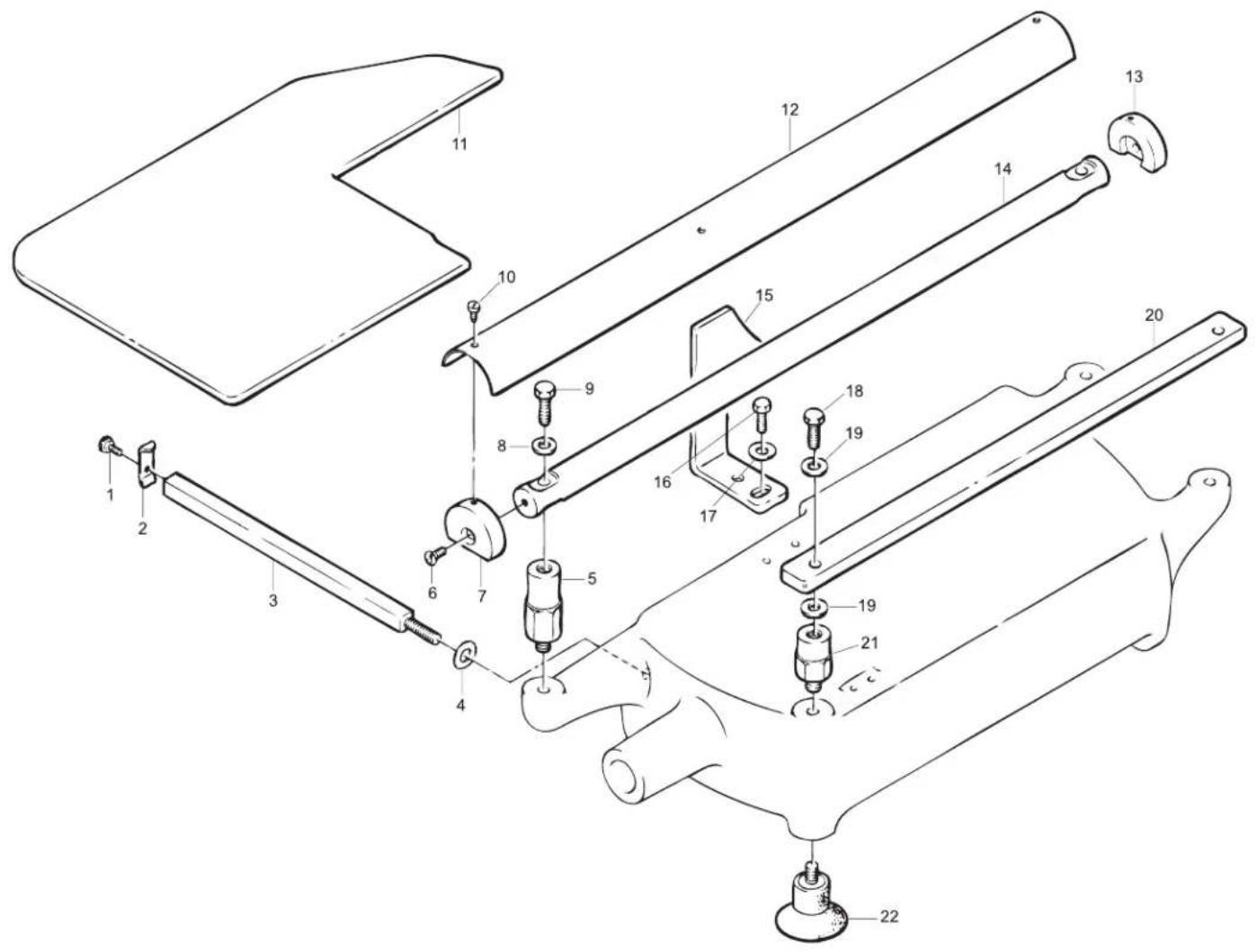
Parts Breakdown
Model MS-IT-0300-M 13634 Rapid Approach

Model MS-IT-0300-M 13634 Blade Assembly
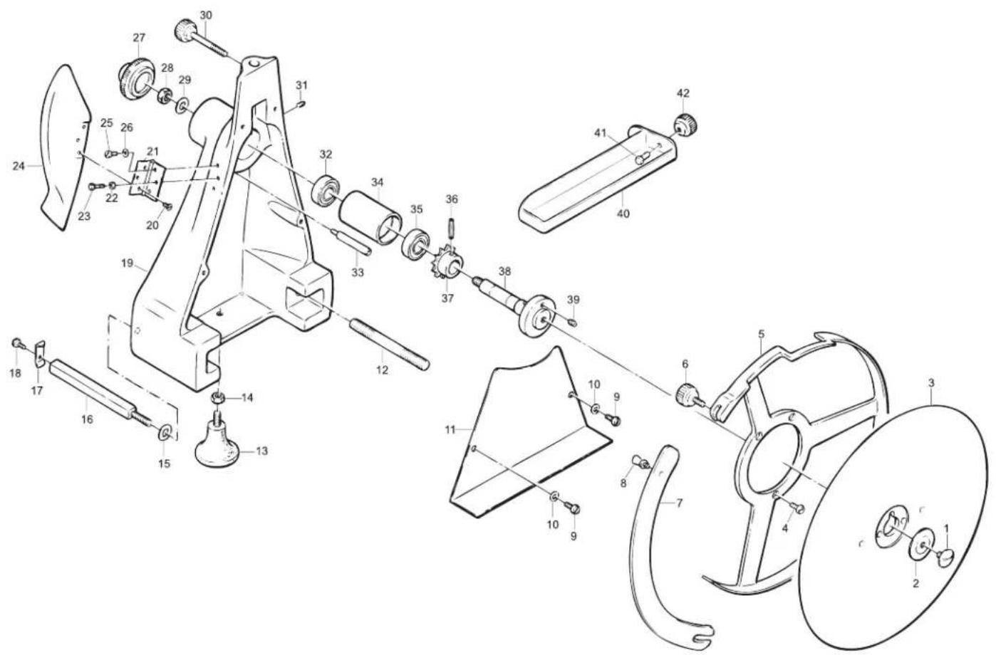
Parts Breakdown
Model MS-IT-0300-M 13634
Cart
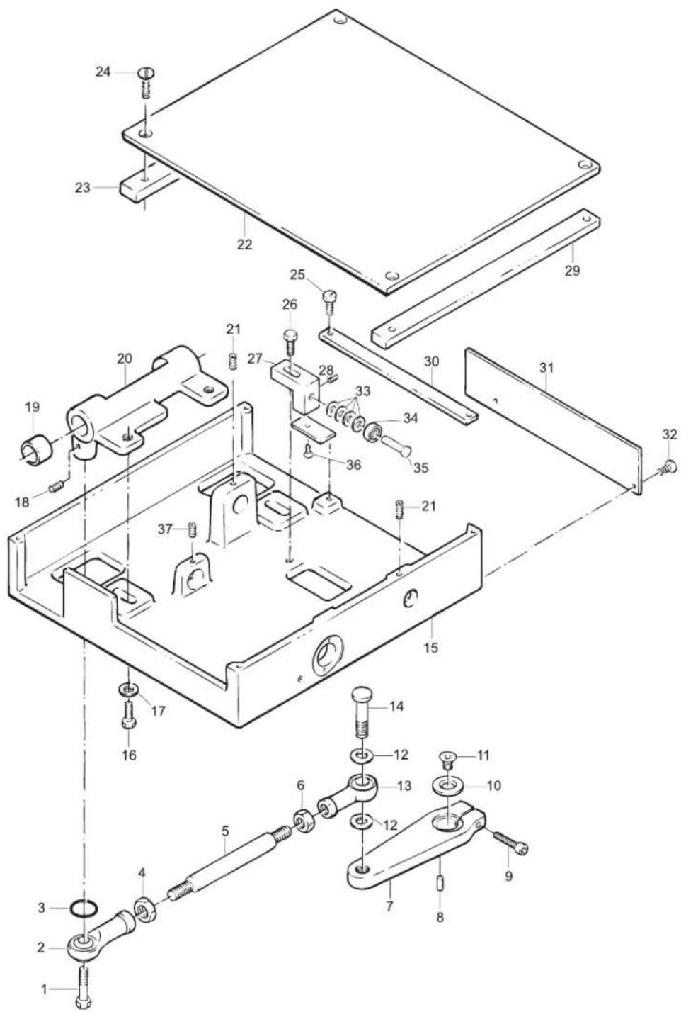
Model MS-IT-0300-M 13634 Thickness Adjustor
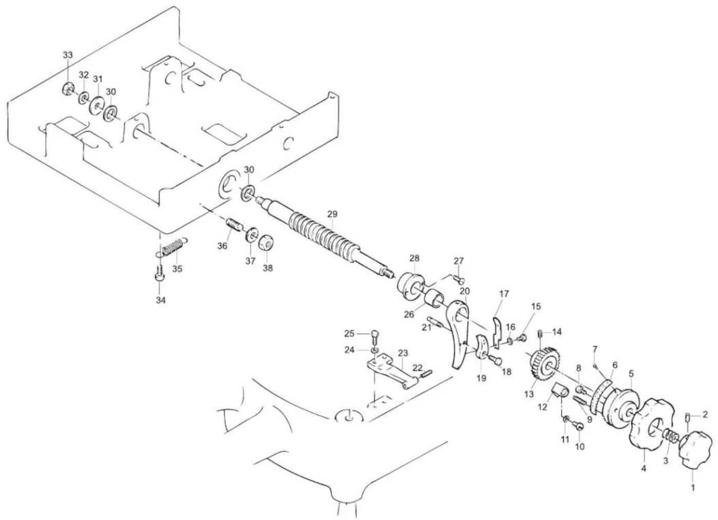
Parts Breakdown
Model MS-IT-0300-M 13634 Meat Tray Assembly
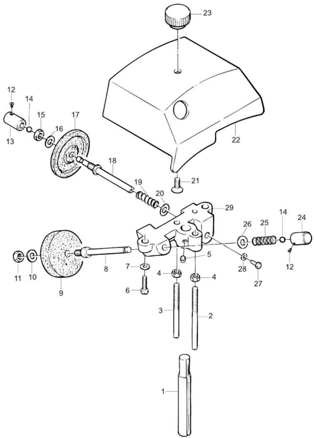
Model MS-IT-0300-M 13634 Sharpening Assembly
Parts Breakdown
Model MS-IT-0300-M 13634 Base
| Item No. | Description Position | Item No. | Description P |
| 33047 | Screw | Chrome for 300VO 1 | 33058 Chain Link for 300VO 12 |
| 33048 | Meat Grip Handle for 300VO | 2 | |
| 33049 | Flywheel Handle Shaft for 300VO | 3 | |
| 33050 | Nut 12 MA for 300VO | 4 | |
| 33051 | Screw Chrome for 300VO | 5 | |
| 33052 | Flywheel for 300VO | 6 | |
| 33053 | Set Screw 6x8 for 300VO | 7 | |
| 33054 | Tapered Pin for 300VO | 8 | |
| 33055 | Gear Shaft for 300VO | 9 | |
| 33056 | Bronze Bushing 20x25 for 300VO | 10 | |
| 33057 | Flywheel Casing for 300VO | 11 |
| Position Item No. Description Position | ||
| Washer 12 for 300VO 23 | ||
| 33059 | Fly Chain for 300VO | 13 |
| 33060 | Set Screw 6x8 for 300VO | 14 |
| 33061 | Gear Z45 Pig for 300VO | 15 |
| 33062 | Tapered Pin for 300VO | 16 |
| 33063 | Bronze Bushing 20x25 for 300VO | 17 |
| 33064 | Gear Shaft for 300VO | 18 |
| 33065 | Oiler for 300VO | 19 |
| 33066 | Axial Bearing for 300VO | 20 |
| 33067 | Washer for 300VO | 21 |
| 33068 | Bronze Bushing 20x25 for 300VO | 22 |
| 33070 | Nut 12 MA for 300VO | 24 |
| 33071 | Bronze Bushing 20x25 for 300VO | 25 |
| 33072 | Gear Pivot for 300VO | 26 |
| 33073 | Tapered Pin for 300VO | 27 |
| 33074 | Gear Z16 for 300VO | 28 |
| 33075 | Gear Z32 for 300VO | 29 |
| 33076 | Tapered Pin for 300VO | 30 |
| 33077 | Gear Z16 for 300VO | 31 |
| 33078 | Tapered Pin for 300VO | 32 |
| 33079 | Spacer for 300VO | 33 |
Guide
| Item No. | Description | Position Item No. | Description P |
| 33080 | Thumb Screw for 300VO | 1 | |
| 33081 | Plate Stop for 300VO | 2 | |
| 33082 | Square Bar Support for Plate for 300VO | 3 | |
| 33083 | Washer 8 for 300VO | 4 | |
| 33084 | Slide Bar Support for 300VO | 5 | |
| 33085 | Slide Bar Cap Screw for 300VO | 6 | |
| 33086 | Slide Bar Cap for 300VO | 7 33093 Bracket for 30 | |
| 33087 | Washer 8 for 300VO | 8 33094 Screw TE 6x |
| Position Item No. Description Position | ||
| 33088 | Screw TE 8x30 for 300VO | 9 |
| 33089 | Screw TC 4x10 for 300VO | 10 |
| 37564 | Collection Plate for 300VO | 11 |
| 33090 | Slide Bar Cover for 300VO | 12 |
| 33091 | Slide Bar Cap for 300VO | 13 |
| 33092 | Carriage Slide Bar for 300VO | 14 |
| 0VO | 15 | |
| 6 for 300VO | 16 | |
| 33095 | Washer 6 for 300VO | 17 |
| 33096 | Screw TE 8x20 INOX for 300VO | 18 |
| 33097 | Washer 8 for 300VO | 19 |
| 33098 | Carriage Rail for 300VO | 20 |
| 33099 | Rail Support for 300VO | 21 |
| 33100 | Foot for 300VO | 22 |
Rapid Approach
| Item No. | Description Position | Item No. | Description P |
| 33180 | INOX Rod 15 for 300VO | 1 | |
| 33181 | Spring for 300VO | 2 | |
| 33182 | Screw TC 4x7 for 300VO | 3 | |
| 33183 | Steel Tab for 300VO | 4 | |
| 33184 | Bushing 15 for 300VO | 5 | |
| 33185 | Set Screw 5x8 for 300VO | 6 | |
| 33186 | Slide for 300VO | 7 | |
| 33187 | Handle for 300VO | 8 |
| position Item No. Description Position | ||
| 33188 | Pin for 300VO | 9 |
| 33189 | Lever Plate for 300VO | 10 |
| 33190 | Support Mount for 300VO | 11 |
| 33191 | Spring for 300VO | 12 |
| 33192 | Screw TE 6x16 for 300VO | 13 |
| 33193 | Comb Block for 300VO | 14 |
| 33194 | Screw TPSV 4x7 for 300VO | 15 |
| 33195 | Pivot Rod for 300VO | 16 |
| 33196 | Screw TE 6x16 for 300VO | 17 |
| 33197 | Block Door on Plate for 300VO | 18 |
| 33198 | Washer 6 for 300VO | 19 |
| 33199 | Bearing 626 ZZ for 300VO | 20 |
| 33200 | Bearing Stud for 300VO | 21 |
| 33201 | Set Screw 6x8 for 300VO | 22 |
| 33202 | Screw TE 6x16 for 300VO | 23 |
Model MS-IT-0300-M 13634 Blade Assembly
Item No. Description Position Item No. Description P
| 33101 Screw Chrome for 300VO 1 33115 Washer 8 for 300VO 15 33129 | ||
| 33102 | Blade Washer for 300VO | 2 |
| 24040 | Blade for 300VO | 3 |
| 33104 | Screw TC 5x10 for 300VO | 4 |
| 33105 | Bladening Guard for 300VO | 5 |
| 33106 | Thumb Screw for 300VO | 6 |
| 33107 | Blade Guard for 300VO | 7 |
| 33108 | Blade Guard Thumb Screw for 300VO | 8 |
| 33109 | Screw TC 6x12 for 300VO | 9 |
| 33110 | Washer 6 for 300VO | 10 |
| 33111 | Chain Guard for 300VO | 11 |
| 33112 | Pin for 300VO | 12 |
| 33113 | Foot for 300VO | 13 |
| 33114 | Nut 8 MA for 300VO | 14 |
position Item No. Description Position
| Washer 10 for 300VO | 29 | ||
| 33116 | Carriage Rail for 300VO | 16 | |
| 33117 | Carriage Rail Stop for 300VO | 17 | |
| 33118 | Thumb Screw for 300VO | 18 | |
| 33119 | Blade Assembly Casing for 300VO | 19 | |
| 33120 | Screw TC 3x5 for 300VO | 20 | |
| 33121 | Hinge for 300VO | 21 | |
| 33122 | Nut 4 MA for 300VO | 22 | |
| 33123 | Screw TC 4x20 for 300VO | 23 | |
| 33124 | Meat Deflector for 300VO | 24 | |
| 33125 | Screw TC 4x10 for 300VO | 25 | |
| 33126 | Washer 5 for 300VO | 26 | |
| 33127 | Blade Shaft Cap for 300VO | 27 | |
| 33128 | Nut 10 MA for 300VO | 28 | |
| 33130 | Sharpener Pin for 300VO | 30 |
| 33131 | Set Screw 6x8 for 300VO | 31 |
| 33132 | Bearing 6202 ZZ for 300VO | 32 |
| 33133 | Spacer Ring for 300VO | 33 |
| 33134 | Bearing Sleeve for 300VO | 34 |
| 33135 | Bearing 6202 ZZ for 300VO | 35 |
| 33136 | Rubber Pin 5x28 for 300VO | 36 |
| 33137 | Gear Pig Z15 for 300VO | 37 |
| 33138 | Bearing and Shaft for 300VO | 38 |
| 33139 | Set Screw 6x8 for 300VO | 39 |
| 33140 | Tray for 300VO | 40 |
| 33141 | Screw TE 6x16 for 300VO | 41 |
| 33142 | Thumb Screw for 300VO | 42 |
Cart
Item No. Description Position Item No. Description P
| 33143 | Joint Bolt for 300VO | 1 |
| 33144 | Joint for 300VO | 2 |
| 33145 | O-Ring for 300VO | 3 |
| 33146 | Nut 10 for 300VO | 4 |
| 33147 | Rod Lever for 300VO | 5 |
| 33148 | Nut 10 for 300VO | 6 |
| 33149 | Support Mount for 300VO | 7 |
| 33150 | Pin 5x12 INOX for 300VO | 8 |
| 33151 | Set Screw 6x40 for 300VO | 9 |
| 33152 | Washer 12 for 300VO | 10 |
| 33153 | Screw TPSV 8x16 for 300VO | 11 |
| 33154 | Washer for 300VO | 12 |
| 33155 | Joint for 300VO | 13 |
position Item No. Description Position
| 33156 | Screw TE 10x40 for 300VO | 14 |
| 33157 | Plate Base for 300VO | 15 |
| 33158 | Screw TE 8x20 for 300VO | 16 |
| 33159 | Washer 8 for 300VO | 17 |
| 33160 | Set Screw 5x8 for 300VO | 18 |
| 33161 | Bushing 20x25 for 300VO | 19 |
| 33162 | Carriage Support for 300VO | 20 |
| 33163 | Set Screw 5x8 for 300VO | 21 |
| 33164 | Bottom Plate for 300VO | 22 |
| 33165 | Plate Support Bar for 300VO | 23 |
| 33166 | Screw TPSV 4x18 for 300VO | 24 |
| 33167 | Screw TC 5x10 for 300VO | 25 |
| 33168 | Screw TE 8x20 for 300VO | 26 |
| 33169 | Sharpener Support Bracket for 300VO | 27 |
| 33170 | Set Screw 6x8 for 300VO | 28 |
| 33171 | Plate Support Bar for 300VO | 29 |
| 33172 | Slide Bar for 300VO | 30 |
| 33173 | Bottom Plate Cover for 300VO | 31 |
| 33174 | Screw TPSV 3x7 for 300VO | 32 |
| 33175 | Washer 8 for 300VO | 33 |
| 33176 | Bearing 608 ZZ for 300VO | 34 |
| 33177 | Pin for 300VO | 35 |
| 33178 | Screw TPSV 6x12 for 300VO | 36 |
| 33179 | Set Screw 6x8 for 300VO | 37 |
Parts Breakdown
Model MS-IT-0300-M 13634 Thickness Adjustor
Item No. Description Position Item No. Description P
| 33203 Handle for 300VO 1 33216 Set Screw 6x6 for 300VO 14 33229 | ||
| 33204 | Set Screw 5x8 for 300VO | 2 |
| 33205 | Spring for 300VO | 3 |
| 33206 | Adjustment Wheel for 300VO | 4 |
| 33207 | Cam for 300VO | 5 |
| 33208 | Indicator Numbers for 300VO | 6 |
| 33209 | Copper Rivet for 300VO | 7 |
| 33210 | Screw TC 5x10 for 300VO | 8 |
| 33211 | Set Screw for 300VO | 9 |
| 33212 | Screw TC 4x10 for 300VO | 10 |
| 33213 | Washer for 300VO | 11 |
| 33214 | Bracket for 300VO | 12 |
| 33215 | Gear for 300VO | 13 |
position Item No. Description Position
| Screw TPSV 4x10 for 300VO 27 | ||
| 33217 | Screw TC 4x5 INOX for 300VO | 15 |
| 33218 | Washer 4 for 300VO | 16 |
| 33219 | Small Spring for 300VO | 17 |
| 33220 | Screw TE 6x16 for 300VO | 18 |
| 33221 | Small Skip Latch for 300VO | 19 |
| 33222 | Big Skip Latch for 300VO | 20 |
| 33223 | Set Screw for 300VO | 21 |
| 33224 | Set Screw PVC 8 for 300VO | 22 |
| 33225 | Skip Block for 300VO | 23 |
| 33226 | Washer 6 for 300VO | 24 |
| 33227 | Screw TE 6x20 for 300VO | 25 |
| 33228 | Bushing 12 for 300VO | 26 |
| 33230 | Feed Screw Bushing for 300VO | 28 |
| 33231 | Feed Screw Shaft for 300VO | 29 |
| 33232 | O-Ring for 300VO | 30 |
| 33233 | Washer 6 for 300VO | 31 |
| 33234 | Teflon Nut for 300VO | 32 |
| 33235 | Nut for 300VO | 33 |
| 33236 | Screw TC 4x16 for 300VO | 34 |
| 33237 | Large Spring for 300VO | 35 |
| 33238 | Set Screw for 300VO | 36 |
| 33239 | Washer 8 for 300VO | 37 |
| 33240 | Nut 8 for 300VO | 38 |
Meat Tray Assembly
Item No. Description Position Item No. Description P
| 33241 | Complete Arm Assembly for 300VO | 1 - 35 |
| 33242 | Screw Chrome for 300VO | 36 |
| 33243 | Long Column for 300VO | 37 |
| 33244 | Short Column for 300VO | 38 |
position Item No. Description Position
| 33245 | Spacer for 300VO | 39 |
| 33246 | Thumb Screw for 300VO | 40 |
| 33247 | Set Screw 12 for 300VO | 41 |
| 33248 | Screw TPSV 4x10 for 300VO | 42 |
| 33249 | Plate Lock for 300VO | 43 |
| 33250 | Top Plate for 300VO | 44 |
Sharpening Assembly
Item No. Description Position Item No. Description P
| 33251 | Shaft for Sharpener for 300VO | 1 |
| 33252 | Pin for 300VO | 2 |
| 33253 | Pin for 300VO | 3 |
| 33254 | Nut 5 for 300VO | 4 |
| 33255 | Set Screw 6x8 for 300VO | 5 |
| 33256 | Screw TC 4x16 for 300VO | 6 |
| 33257 | Washer 5 for 300VO | 7 |
| 33258 | Sharpener Pin for 300VO | 8 |
| 18016 | Grinding Stone for 300VO | 9 |
| 33259 | Washer 6 for 300VO | 10 |
| 33260 | Nut 6 for 300VO | 11 |
position Item No. Description Position
| 33261 | Push Button Screw for 300VO | 12 |
| 31196 | Screw for 300VO | 12 |
| 31197 | Sharpener Push Pin for 300VO | 13 |
| 33262 | Sharpener Push Button for 300VO | 13 |
| 33263 | Ball Bearing for 300VO | 14 |
| 33264 | Nut 6 for 300VO | 15 |
| 33265 | Washer 6 for 300VO | 16 |
| 33545 | Finishing Stone for 300VO | 17 |
| 33266 | Sharpener Pin for 300VO | 18 |
| 31198 | Shaft for 300VO | 18 |
| 33267 | Spring for 300VO | 19 |
| 33268 | Washer 6 for 300VO | 20 |
| 33269 | Screw TPSV 6x12 for 300VO | 21 |
| 33270 | Sharpener Cover for 300VO | 22 |
| 33271 | Sharpener Cover Knob for 300VO | 23 |
| 33272 | Sharpener Push Button for 300VO | 24 |
| 33273 | Spring for 300VO | 25 |
| 33274 | Washer for 300VO | 26 |
| 33275 | Screw TC 3 for 300VO | 27 |
| 33276 | Washer 3 for 300VO | 28 |
| 33277 | Sharpener Body for 300VO | 29 |
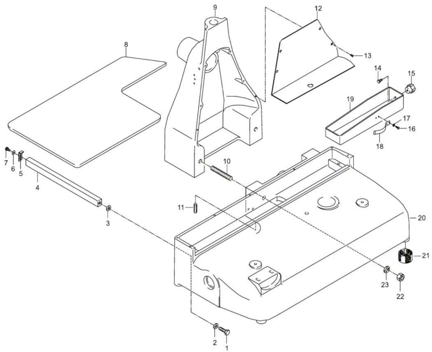
Parts Breakdown
Model MS-IT-0350-M 13639 Base
Parts Breakdown
Model MS-IT-0350-M 13639 Flywheel

Model MS-IT-0350-M 13639 Blade Assembly
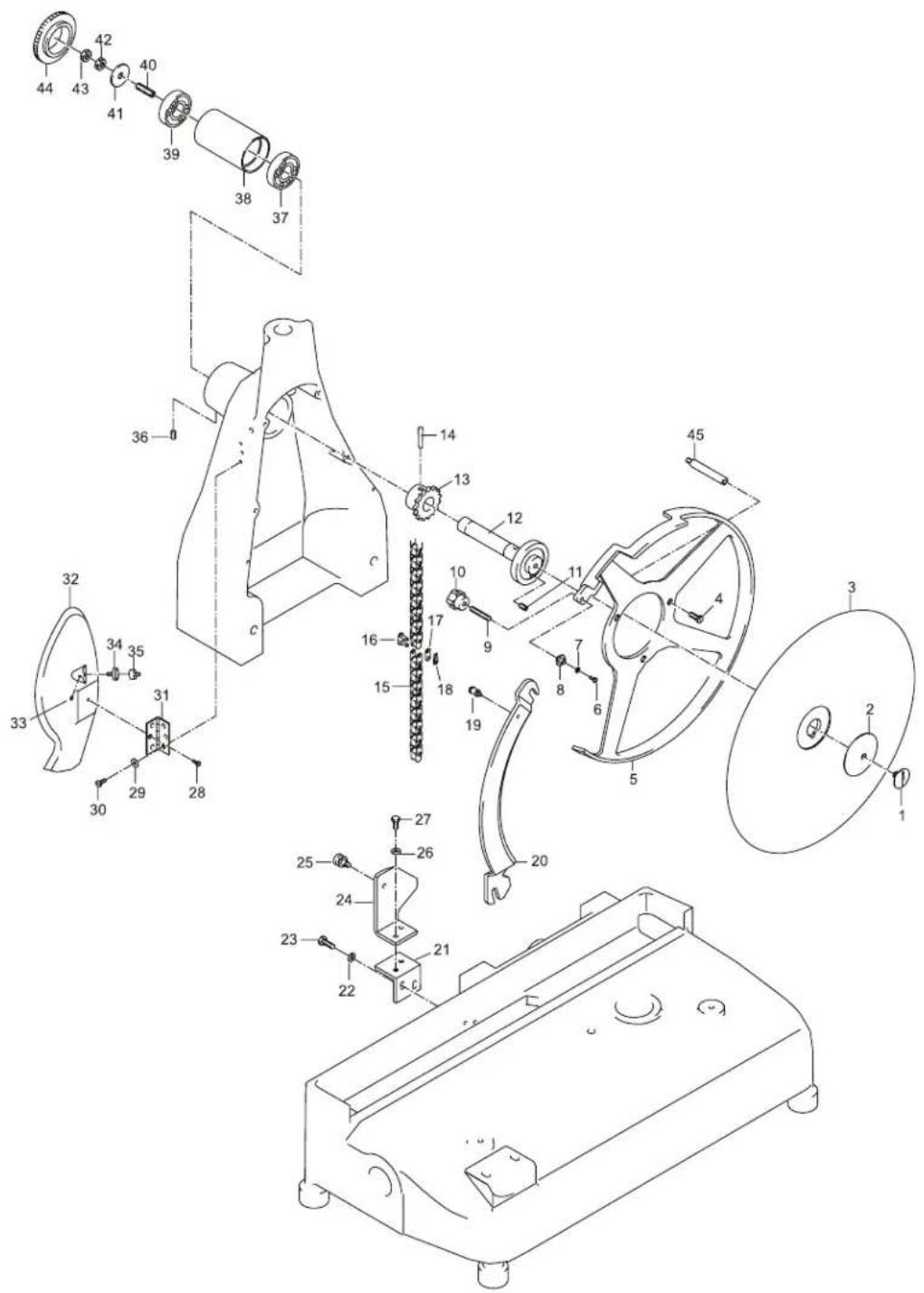
Parts Breakdown
Model MS-IT-0350-M 13639 Sharpening Assembly
Parts Breakdown
CartMod
Parts Breakdown
Model MS-IT-0350-M 13639 Meat Tray Assembly
Model MS-IT-0350-M 13639 Advancement Cart
Parts Breakdown
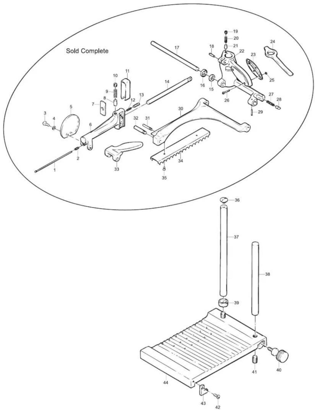
Model MS-IT-0350-M 13639 Support Stand
Sold Complete
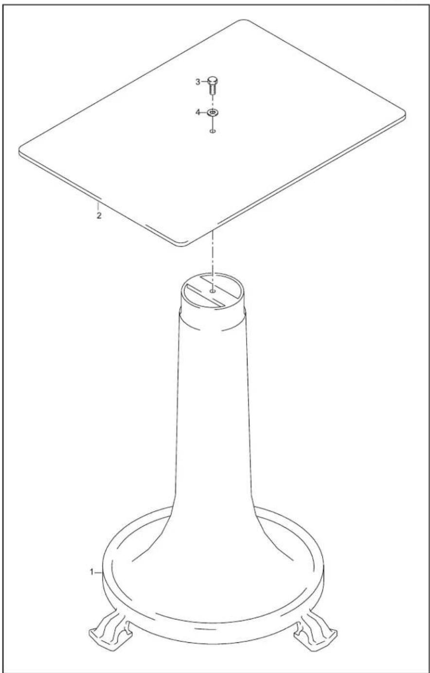
Model MS-IT-0350-M 13639 Base
Item No. Description Position Item No. Description P
| 33278 Screw TE for 350VO 1 33286 Blade Assembly Casing for 350VO 9 | ||
| 33279 | Washer for 350VO | 2 |
| 33280 | Washer for 350VO | 3 |
| 33281 | Square Bar Support for Plate for 350VO | 4 |
| 33282 | Plate Stop for 350VO | 5 |
| 33283 | Washer for 350VO | 6 |
| 33284 | Screw for 350VO | 7 |
33285 Tray for 350VO
position Item No. Description Position
| 33294 Washer for 350VO | 17 | |
| 33287 | Pin for 350VO | 10 |
| 33288 | Pin for 350VO | 11 |
| 33289 | Chain Guard for 350VO | 12 |
| 33290 | Screw for 350VO | 13 |
| 33291 | Screw for 350VO | 14 |
| 33292 | Thumb Screw for 350VO | 15 |
8 33293 Screw for 350VO 16
| 33295 | Spring for 350VO | 18 |
| 33296 | Tray for 350VO | 19 |
| 33297 | Housing for 350VO | 20 |
| 33298 | Foot for 350VO | 21 |
| 33299 | Nut for 350VO | 22 |
| 33300 | Washer for 350VO | 23 |
Flywheel
Item No. Description Position Item No. Description P
| 33301 | Gear Pivot for 350VO | 1 |
| 33302 | Gear for 350VO | 2 |
| 33303 | Rod / Counter for 350VO | 3 |
| 33304 | Set Screw for 350VO | 4 |
| 33305 | Screw for 350VO | 5 |
| 33306 | Washer for 350VO | 6 |
| 33307 | Joint for 350VO | 7 |
| 33308 | Screw for 350VO | 8 |
| 33309 | Nut for 350VO | 9 |
| 33310 | Pin for 350VO | 10 |
| 33311 | Nut for 350VO | 11 |
| 33312 | Joint for 350VO | 12 |
| 33313 | Washer for 350VO | 13 |
| 33314 | Washer for 350VO | 14 |
| 33315 | Carriage Slide Bar for 350VO | 15 |
| 33316 | Axial Bearing for 350VO | 16 |
| 33317 | Axial Bearing for 350VO | 17 |
| 33318 | Axial Bearing for 350VO | 18 |
position Item No. Description Position
| 33319 | Axial Bearing for 350VO | 19 |
| 33320 | Gear for 350VO | 20 |
| 33321 | Tapered Pin for 350VO | 21 |
| 33322 | Gear for 350VO | 22 |
| 33323 | Tapered Pin for 350VO | 23 |
| 33324 | Axial Bearing for 350VO | 24 |
| 33325 | Axial Bearing for 350VO | 25 |
| 33326 | Axial Bearing for 350VO | 26 |
| 33327 | Screw Chrome for 350VO | 27 |
| 33328 | Meat Grip Handle for 350VO | 28 |
| 33329 | Pin for 350VO | 29 |
| 33330 | Nut for 350VO | 30 |
| 33331 | Tapered Pin for 350VO | 31 |
| 33332 | Screw Chrome for 350VO | 32 |
| 33333 | Fly Wheel for 350VO | 33 |
| 33334 | Set Screw for 350VO | 34 |
| 33350 | Bearing for 350VO | 35 |
| 33336 | Bushing for 350VO | 36 |
| 33337 | Oiler for 350VO | 37 |
| 33338 | Oiler for 350VO | 38 |
| 33339 | Bushing for 350VO | 39 |
| 33340 | Gear Shaft for 350VO | 40 |
| 33341 | Axial Bearing for 350VO | 41 |
| 33342 | Axial Bearing for 350VO | 42 |
| 33343 | Axial Bearing for 350VO | 43 |
| 33344 | Set Screw for 350VO | 44 |
| 33345 | Gear for 350VO | 45 |
| 33346 | Cap for 350VO | 46 |
| 33347 | Screw for 350VO | 47 |
| 33348 | Pin for 350VO | 48 |
| 33349 | Washer for 350VO | 49 |
| 33350 | Bearing for 350VO | 50 |
| 33351 | Spacer for 350VO | 51 |
| 33352 | Bearing for 350VO | 52 |
Parts Breakdown
Model MS-IT-0350-M 13639 Blade Assembly
Item No. Description Position Item No. Description P
| 33353 Screw Chrome for 350VO 1 33368 Chain Link for 350VO 16 33383 | ||
| 33354 | Blade Washer for 350VO | 2 |
| 24041 | Blade for 350VO | 3 |
| 33356 | Screw TC 5 X 10 for 350VO | 4 |
| 33357 | Bladering Guard for 350VO | 5 |
| 33358 | Screw for 350VO | 6 |
| 33359 | Washer for 350VO | 7 |
| 33360 | Spacer for 350VO | 8 |
| 33361 | Set Screw for 350VO | 9 |
| 33362 | Thumb Screw for 350VO | 10 |
| 33363 | Set Screw for 350VO | 11 |
| 33364 | Bearing and Shaft for 350VO | 12 |
| 33365 | Gear Pig Z 15 for 350VO | 13 |
| 33366 | Tapered Pin for 350VO | 14 |
| 33367 | Chain for 350VO | 15 |
position Item No. Description Position
| Hinge for 350VO 31 | ||
| 33369 | Chain Link for 350VO | 17 |
| 33370 | Chain Link for 350VO | 18 |
| 33371 | Thumb Screw for 350VO | 19 |
| 33372 | Blade Guard for 350VO | 20 |
| 33373 | Bracket for 350VO | 21 |
| 33374 | Washer for 350VO | 22 |
| 33375 | Screw for 350VO | 23 |
| 33376 | Bracket for 350VO | 24 |
| 33377 | Screw for 350VO | 25 |
| 33378 | Washer for 350VO | 26 |
| 33379 | Screw for 350VO | 27 |
| 33380 | Screw for 350VO | 28 |
| 33381 | Washer for 350VO | 29 |
| 33382 | Screw for 350VO | 30 |
| 33384 | Meat Deflector for 350VO | 32 |
| 33385 | Set Screw for 350VO | 33 |
| 33386 | Screw for 350VO | 34 |
| 33387 | Screw for 350VO | 35 |
| 33388 | Set Screw for 350VO | 36 |
| 33389 | Bearing for 350VO | 37 |
| 33390 | Bearing Sleeve for 350VO | 38 |
| 33391 | Bearing for 350VO | 39 |
| 33392 | Pin for 350VO | 40 |
| 33393 | Washer for 350VO | 41 |
| 33394 | Nut for 350VO | 42 |
| 33395 | Nut for 350VO | 43 |
| 33396 | Blade Shaft Cap for 350VO | 44 |
| 39117 | Support Pin for 350VO | 45 |
Sharpening Assembly
Item No. Description Position Item No. Description P
| 33537 | Pin for 350VO | 1 |
| 33538 | Knob for 350VO | 2 |
| 33539 | Shaft for Sharpener for 350VO | 3 |
| 33540 | Pin for 350VO | 4 |
| 33541 | Nut for 350VO | 5 |
| 33542 | Pin for 350VO | 6 |
| 33543 | Nut for 350VO | 7 |
| 33544 | Sharpener Pin for 350VO | 8 |
| 18016 | Grinding Stone for 350VO | 9 |
| 33546 | Washer for 350VO | 10 |
| 33547 | Nut for 350VO | 11 |
| 33548 | Push Button Screw for 350VO | 12 |
position Item No. Description Position
| 33549 | Sharpener Push Button for 350VO | 13 |
| 33550 | Ball Bearing for 350VO | 14 |
| 33551 | Nut for 350VO | 15 |
| 33552 | Washer for 350VO | 16 |
| 33545 | Finishing Stone for 350VO | 17 |
| 33554 | Sharpener Pin for 350VO | 18 |
| 33555 | Spring for 350VO | 19 |
| 33556 | Washer for 350VO | 20 |
| 33557 | Screw for 350VO | 21 |
| 33558 | Sharpener Cover for 350VO | 22 |
| 33559 | Sharpener Cover Knob for 350VO | 23 |
| 33560 | Sharpener Push Button for 350VO | 24 |
| 33561 | Push Button Screw for 350VO | 25 |
| 33562 | Ball Bearing for 350VO | 26 |
| 33563 | Spring for 350VO | 27 |
| 33564 | Washer for 350VO | 28 |
| 33565 | Set Screw for 350VO | 29 |
| 33566 | Screw for 350VO | 30 |
| 33567 | Washer for 350VO | 31 |
| 33568 | Sharpener Body for 350VO | 32 |
| 33569 | Screw for 350VO | 33 |
| 33570 | Washer for 350VO | 34 |
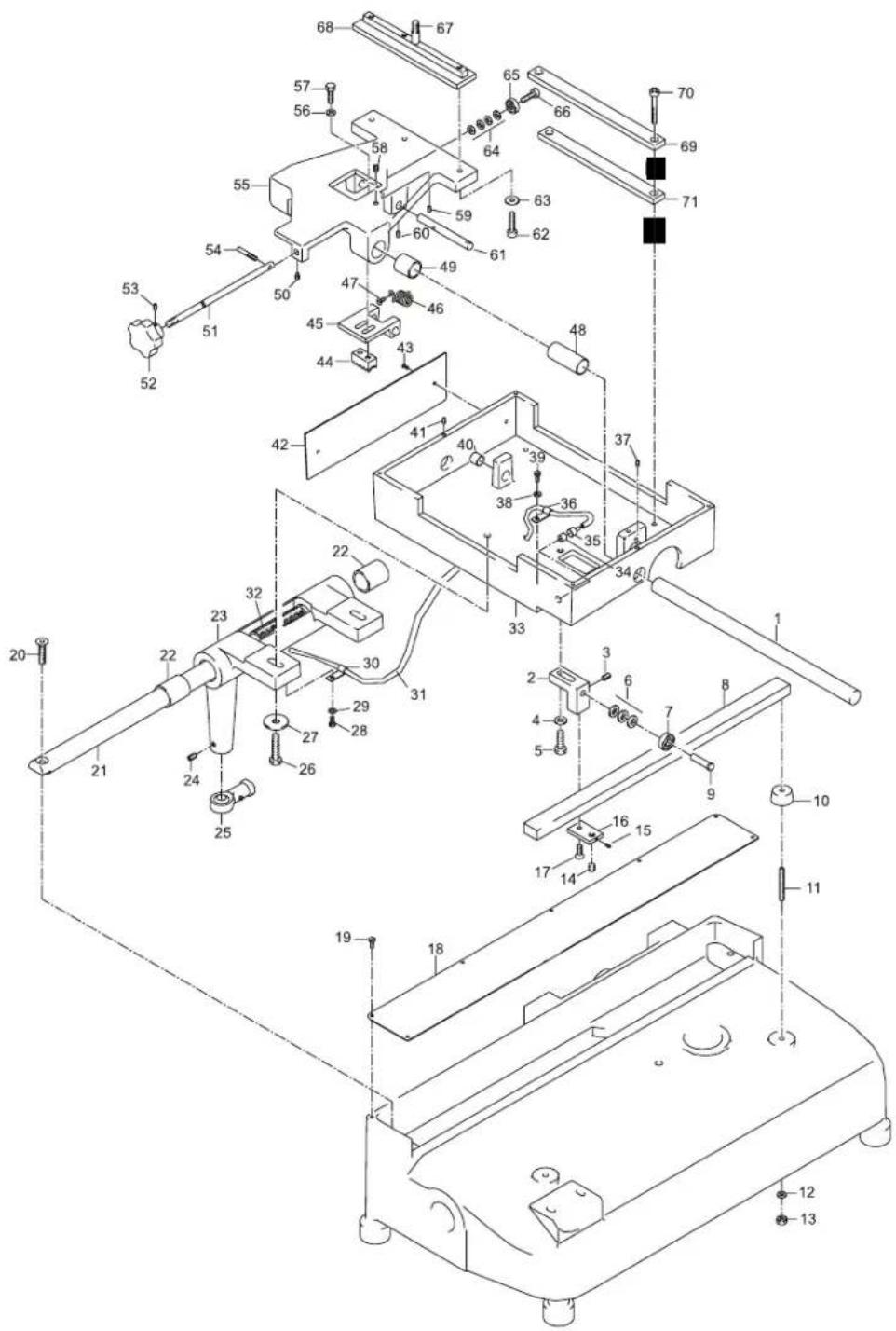
Model MS-IT-0350-M 13639 Cart
Item No. Description Position Item No. Description P
| 33397 Rod for 350VO 1 33422 Screw for 350VO 26 33447 Rod for 350VO | ||
| 33398 | Sharpener Support Bracket for 350VO | 2 |
| 33399 | Set Screw for 350VO | 3 |
| 33400 | Washer for 350VO | 4 |
| 33401 | Screw for 350VO | 5 |
| 33402 | Washer for 350VO | 6 |
| 33403 | Bearing for 350VO | 7 |
| 33404 | Carriage Rail for 350VO | 8 |
| 33405 | Pin for 350VO | 9 |
| 33406 | Foot for 350VO | 10 |
| 33407 | Pin for 350VO | 11 |
| 33408 | Washer for 350VO | 12 |
| 33409 | Nut for 350VO | 13 |
| 33410 | Set Screw for 350VO | 14 |
| 33411 | Set Screw for 350VO | 15 |
| 33412 | Flat Bracket for 350VO | 16 |
| 33413 | Screw for 350VO | 17 |
| 33414 | Slide Bar Cover for 350VO | 18 |
| 33415 | Screw for 350VO | 19 |
| 33416 | Screw for 350VO | 20 |
| 33417 | Carriage Slide Bar for 350VO | 21 |
| 33418 | Bushing for 350VO | 22 |
| 33419 | Carriage Support for 350VO | 23 |
| 33420 | Set Screw for 350VO | 24 |
| 33421 | Joint for 350VO | 25 |
| 51 | ||
| 33423 | Washer for 350VO | 27 |
| 33424 | Screw for 350VO | 28 |
| 33425 | Washer for 350VO | 29 |
| 33426 | Wire Bracket for 350VO | 30 |
| 33427 | Cable for 350VO | 31 |
| 33428 | Wick for 350VO | 32 |
| 33429 | Plate Base for 350VO | 33 |
| 33430 | Screw for 350VO | 34 |
| 33431 | Screw for 350VO | 35 |
| 33432 | Wire Bracket for 350VO | 36 |
| 33433 | Set Screw for 350VO | 37 |
| 33434 | Washer for 350VO | 38 |
| 33435 | Screw for 350VO | 39 |
| 33436 | Bushing for 350VO | 40 |
| 33437 | Set Screw for 350VO | 41 |
| 33438 | Bottom Plate Cover for 350VO | 42 |
| 33439 | Screw for 350VO | 43 |
| 33440 | Comb Block for 350VO | 44 |
| 33441 | Support Mount for 350VO | 45 |
| 33442 | Spring for 350VO | 46 |
| 33443 | Screw for 350VO | 47 |
| 33444 | Bushing for 350VO | 48 |
| 33445 | Bushing for 350VO | 49 |
| 33446 | Set Screw for 350VO | 50 |
| 33448 | Knob for 350VO | 52 |
| 33449 | Set Screw for 350VO | 53 |
| 33450 | Pin for 350VO | 54 |
| 33451 | Slide for 350VO | 55 |
| 33452 | Washer for 350VO | 56 |
| 33453 | Screw for 350VO | 57 |
| 33454 | Set Screw for 350VO | 58 |
| 33455 | Set Screw for 350VO | 59 |
| 33456 | Set Screw for 350VO | 60 |
| 33457 | Tapered Pin for 350VO | 61 |
| 33458 | Screw for 350VO | 62 |
| 33459 | Washer for 350VO | 63 |
| 33460 | Washer for 350VO | 64 |
| 33461 | Bearing for 350VO | 65 |
| 33462 | Pin for 350VO | 66 |
| 33463 | Pin for 350VO | 67 |
| 33464 | Mount for 350VO | 68 |
| 33465 | Plate for 350VO | 69 |
| 33466 | Screw for 350VO | 70 |
| 33467 | Plate for 350VO | 71 |
| 33468 | Washer for 350VO | 73 |
| 33469 | Washer for 350VO | 74 |
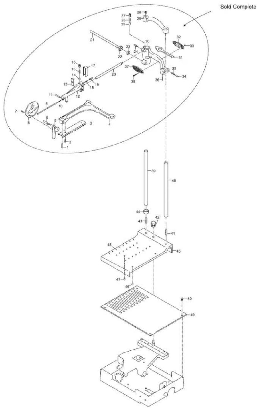
Meat Tray Assembly
| Item No. | Description Position Item No. | Description P |
| 33524 | Complete Arm Assembly for 350VO | 1 - 38 |
| 33525 | Column for 350VO | 39 |
| 33526 | Column for 350VO | 40 |
| 33527 | Set Screw for 350VO | 41 |
| 33528 | Tightening Knob for 350VO | 42 |
| Position Item No. Description Position | ||
| 33529 | Set Screw for 350VO | 43 |
| 33530 | Spacer for 350VO | 44 |
| 33531 | Top Plate for 350VO | 45 |
| 33532 | Set Screw for 350VO | 46 |
| 33533 | Set Screw for 350VO | 47 |
| 33534 | Steel Pin for 350VO | 48 |
| 33535 | Bottom Plate for 350VO | 49 |
| 33536 | Screw for 350VO | 50 |
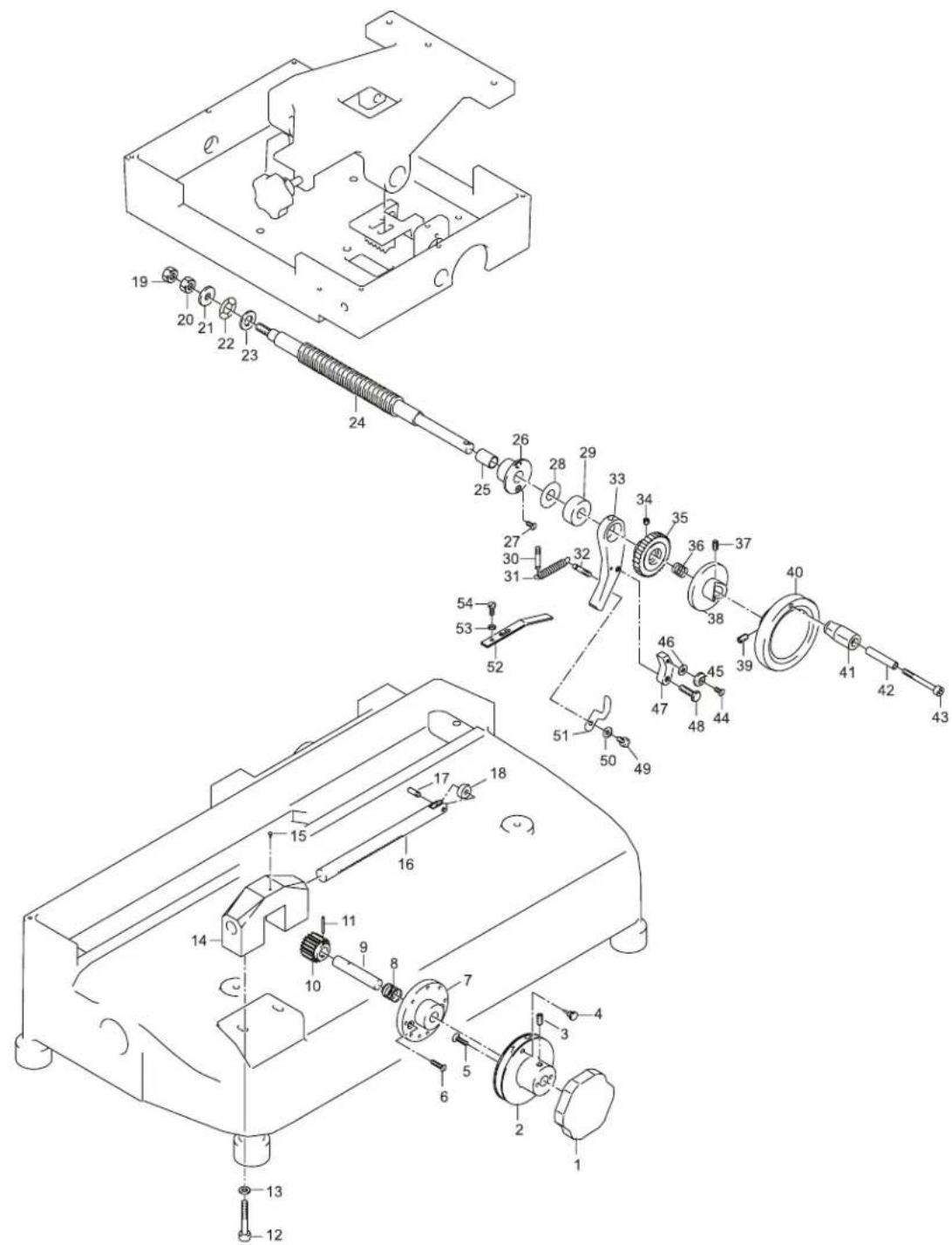
Parts Breakdown
Model MS-IT-0350-M 13639 Advancement Cart
| Item No. | Description Position | Item No. | Description P |
| 33470 | Index Knob for 350VO 1 33488 Nut for 350VO 19 33506 Set Screw | ||
| 33471 | Indicator Numbers for 350VO | 2 | |
| 33472 | Set Screw for 350VO | 3 | |
| 33473 | Screw for 350VO | 4 | |
| 33474 | Screw for 350VO | 5 | |
| 33475 | Screw for 350VO | 6 | |
| 33476 | Cam for 350VO | 7 | |
| 33477 | Spring for 350VO | 8 | |
| 33478 | Pin for 350VO | 9 | |
| 33479 | Gear for 350VO | 10 | |
| 33480 | Tapered Pin for 350VO | 11 | |
| 33481 | Screw for 350VO | 12 | |
| 33482 | Washer for 350VO | 13 | |
| 33483 | Index Mount for 350VO | 14 | |
| 33484 | Rivet for 350VO | 15 | |
| 33485 | Cam Pin for 350VO | 16 | |
| 33486 | Set Screw for 350VO | 17 | |
| 33487 | Bearing PVC for 350VO | 18 | |
| position Item No. Description Position | ||
| for 350VO | 37 | |
| 33489 | Nut for 350VO | 20 |
| 33490 | Washer for 350VO | 21 |
| 33491 | Wavy Washer for 350VO | 22 |
| 33492 | Washer for 350VO | 23 |
| 33493 | Feed Screw Shaft for 350VO | 24 |
| 33494 | Bushing for 350VO | 25 |
| 33495 | Feed Screw Bushing for 350VO | 26 |
| 33496 | Screw for 350VO | 27 |
| 33497 | Washer for 350VO | 28 |
| 33498 | Spacer for 350VO | 29 |
| 33499 | Pin for 350VO | 30 |
| 33500 | Spring for 350VO | 31 |
| 33501 | Pin for 350VO | 32 |
| 33502 | Large Skip Latch for 350VO | 33 |
| 33503 | Set Screw for 350VO | 34 |
| 33504 | Gear for 350VO | 35 |
| 33505 | Spring for 350VO | 36 |
| 33507 | Wheel Plate for 350VO | 38 |
| 33508 | Set Screw for 350VO | 39 |
| 33509 | Fly Wheel for 350VO | 40 |
| 33510 | Handle for 350VO | 41 |
| 33511 | Pin for 350VO | 42 |
| 33512 | Socket Head Screw for 350VO | 43 |
| 33513 | Screw for 350VO | 44 |
| 33514 | Nut for 350VO | 45 |
| 33515 | Washer for 350VO | 46 |
| 33516 | Small Skip Latch for 350VO | 47 |
| 33517 | Screw for 350VO | 48 |
| 33518 | Screw for 350VO | 49 |
| 33519 | Washer for 350VO | 50 |
| 33520 | Spring for 350VO | 51 |
| 33521 | Spring for 350VO | 52 |
| 33522 | Washer for 350VO | 53 |
| 33523 | Screw for 350VO | 54 |
Support Stand
Item No. Description Position
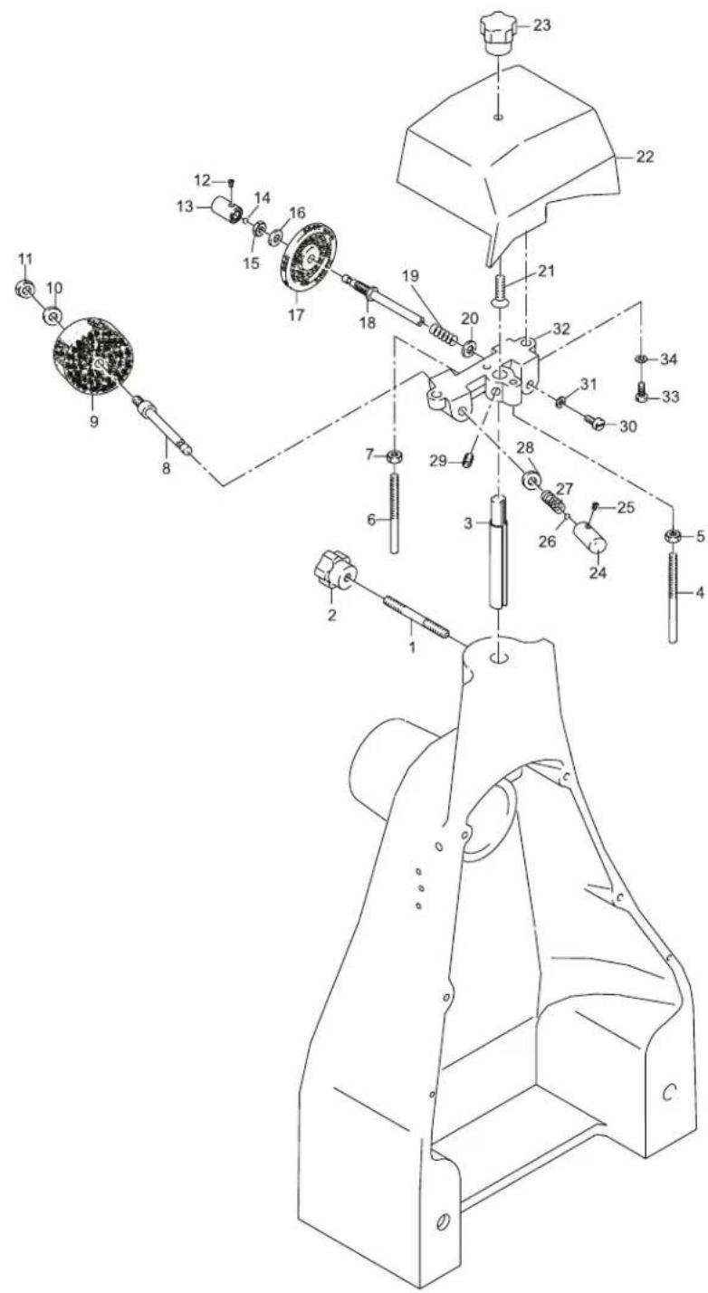
33571 Pedestal Base for 350VO 1 - 4
Parts Breakdown
Model MS-IT-0370-M 18830 Stand
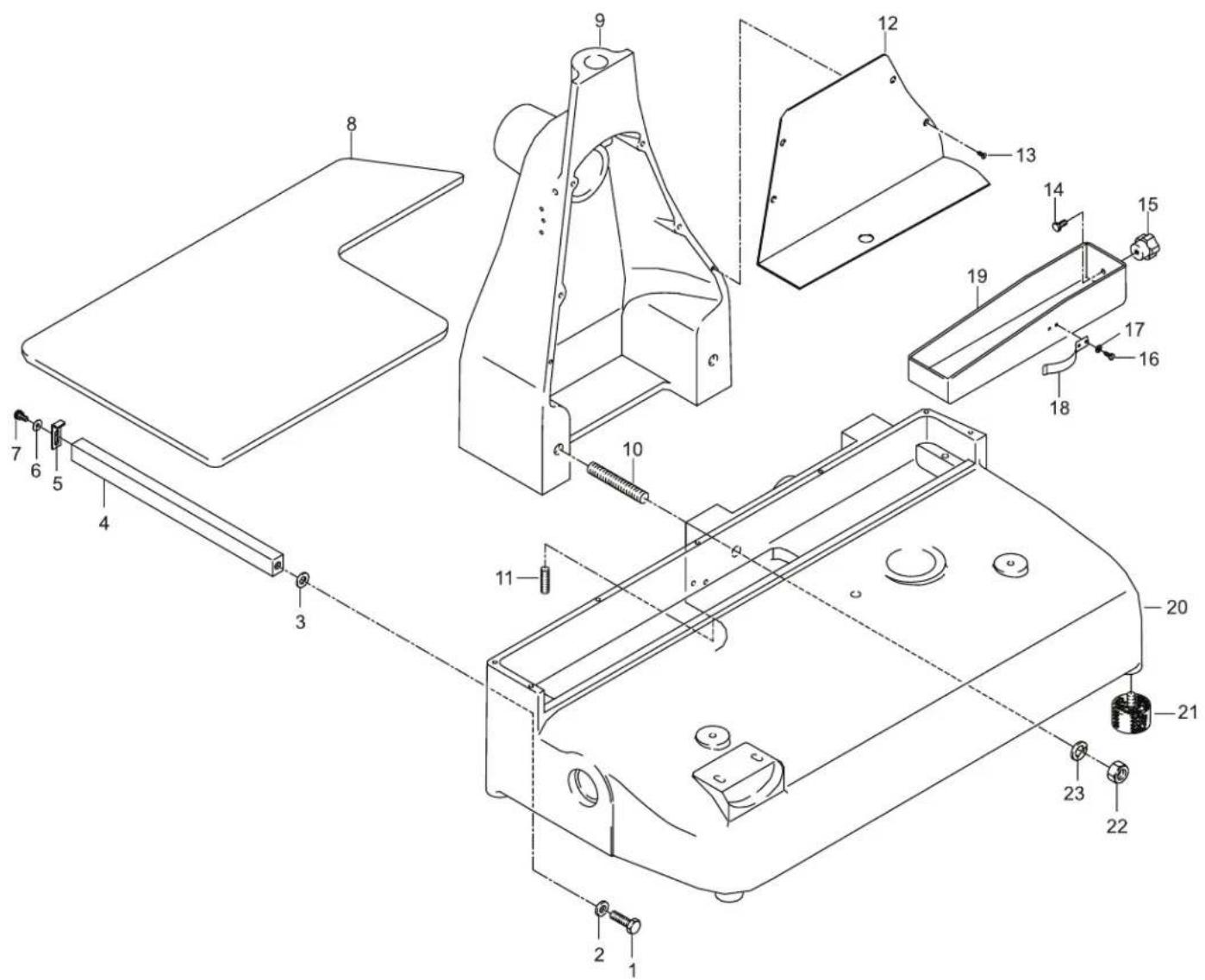
Parts Breakdown
Model MS-IT-0370-M 18830 Flywheel
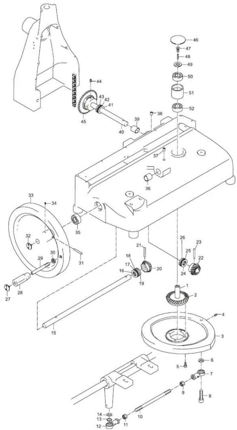
Model MS-IT-0370-M 18830 Blade Assembly
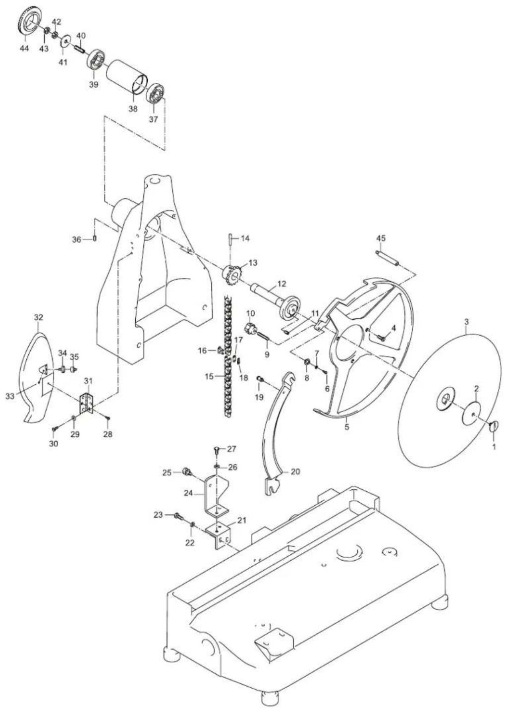
Parts Breakdown
Model MS-IT-0370-M 18830
Advancement Cart
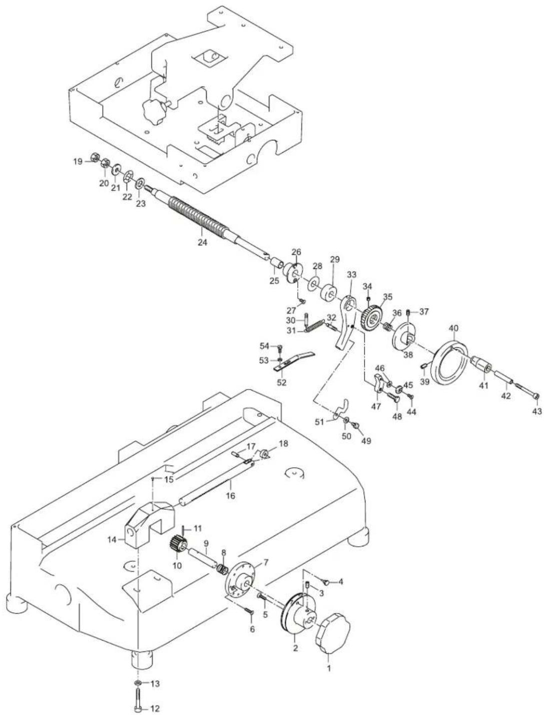
Parts Breakdown
Model MS-IT-0370-M 18830
Cart
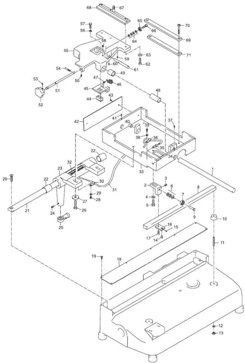
Parts Breakdown
Model MS-IT-0370-M 18830 Meat Tray Assembly
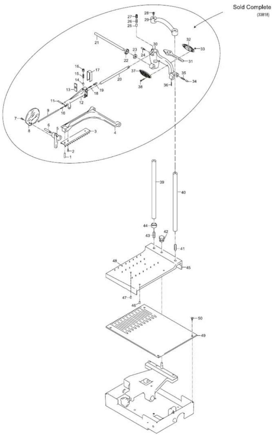
Model MS-IT-0370-M 18830 Sharpening Assembly
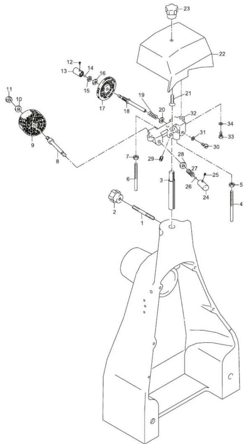
Parts Breakdown
Model MS-IT-0370-M 18830 Support Stand
Sold Complete
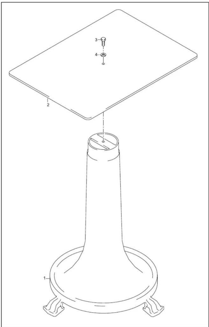
Model MS-IT-0370-M 18830 Stand
Item No. Description Position Item No. Description P
| 33572 Screw TE for 370VO 1 33580 Blade Assembly Casing for 370VO 9 | ||
| 33573 | Washer for 370VO | 2 |
| 33574 | Washer for 370VO | 3 |
| 33575 | Square Bar Support for Plate for 370VO | 4 |
| 33576 | Plate Stop for 370VO | 5 |
| 33577 | Washer for 370VO | 6 |
| 33578 | Screw for 370VO | 7 |
33579 Tray for 370VO
position Item No. Description Position
| 33588 Washer for 370VO | 17 | |
| 33581 | Pin for 370VO | 10 |
| 33582 | Pin for 370VO | 11 |
| 33583 | Chain Guard for 370VO | 12 |
| 33584 | Screw for 370VO | 13 |
| 33585 | Screw for 370VO | 14 |
| 33586 | Thumb Screw for 370VO | 15 |
8 33587 Screw for 370VO 16
| 33589 | Spring for 370VO | 18 |
| 33590 | Tray for 370VO | 19 |
| 33591 | Housing for 370VO | 20 |
| 33592 | Foot for 370VO | 21 |
| 33593 | Nut for 370VO | 22 |
| 33594 | Washer for 370VO | 23 |
Flywheel
Item No. Description Position Item No. Description P
| 33595 | Gear Pivot for 370VO | 1 |
| 33596 | Gear for 370VO | 2 |
| 33597 | Rod / Counter for 370VO | 3 |
| 33598 | Set Screw for 370VO | 4 |
| 33599 | Screw for 370VO | 5 |
| 33600 | Washer for 370VO | 6 |
| 33601 | Joint for 370VO | 7 |
| 33602 | Screw for 370VO | 8 |
| 33603 | Nut for 370VO | 9 |
| 33604 | Pin for 370VO | 10 |
| 33605 | Nut for 370VO | 11 |
| 33606 | Joint for 370VO | 12 |
| 33607 | Washer for 370VO | 13 |
| 33608 | Washer for 370VO | 14 |
| 33609 | Carriage Slide Bar for 370VO | 15 |
| 33610 | Axial Bearing for 370VO | 16 |
| 33611 | Axial Bearing for 370VO | 17 |
| 33612 | Axial Bearing for 370VO | 18 |
position Item No. Description Position
| 33613 | Axial Bearing for 370VO | 19 |
| 33614 | Gear for 370VO | 20 |
| 33615 | Tappered Pin for 370VO | 21 |
| 33616 | Gear for 370VO | 22 |
| 33617 | Tappered Pin for 370VO | 23 |
| 33618 | Axial Bearing for 370VO | 24 |
| 33619 | Axial Bearing for 370VO | 25 |
| 33620 | Axial Bearing for 370VO | 26 |
| 33621 | Screw Chrome for 370VO | 27 |
| 33622 | Meat Grip Handle for 370VO | 28 |
| 33623 | Pin for 370VO | 29 |
| 33624 | Nut for 370VO | 30 |
| 33625 | Tappered Pin for 370VO | 31 |
| 33626 | Screw Chrome for 370VO | 32 |
| 33627 | Fly Wheel for 370VO | 33 |
| 33628 | Set Screw for 370VO | 34 |
| 33629 | Bearing for 370VO | 35 |
| 33630 | Bushing for 370VO | 36 |
| 33631 | Oiler for 370VO | 37 |
| 33632 | Oiler for 370VO | 38 |
| 33633 | Bushing for 370VO | 39 |
| 33634 | Gear Shaft for 370VO | 40 |
| 33635 | Axial Bearing for 370VO | 41 |
| 33636 | Axial Bearing for 370VO | 42 |
| 33637 | Axial Bearing for 370VO | 43 |
| 33638 | Set Screw for 370VO | 44 |
| 33639 | Gear for 370VO | 45 |
| 33640 | Cap for 370VO | 46 |
| 33641 | Screw for 370VO | 47 |
| 33642 | Pin for 370VO | 48 |
| 33643 | Washer for 370VO | 49 |
| 33644 | Bearing for 370VO | 50 |
| 33645 | Spacer for 370VO | 51 |
| 33646 | Bearing for 370VO | 52 |
Parts Breakdown
Model MS-IT-0370-M 18830
Blade Assembly
Item No. Description Position Item No. Description P
| 33647 Screw Chrome for 370VO 1 33662 Chain Link for 370VO 16 33677 | ||
| 33648 Blade Washer for 370VO 2 33663 Chain Link for 370VO 17 33678 | ||
| 33649 | Blade for 370VO | 3 |
| 33650 | Screw TC 5 X 10 for 370VO | 4 |
| 33651 | Bladering Guard for 370VO | 5 |
| 33652 | Screw for 370VO | 6 |
| 33653 | Washer for 370VO | 7 |
| 33654 | Spacer for 370VO | 8 |
| 33655 | Set Screw for 370VO | 9 |
| 33656 | Thumb Screw for 370VO | 10 |
| 33657 | Set Screw for 370VO | 11 |
| 33658 | Bearing and Shaft for 370VO | 12 |
| 33659 | Gear Pig Z 15 for 370VO | 13 |
| 33660 | Tappered Pin for 370VO | 14 |
| 33661 | Chain for 370VO | 15 |
position Item No. Description Position
| Hinge for 370VO 31 | ||
| Meat Defector for 370VO | 32 | |
| 33664 | Chain Link for 370VO | 18 |
| 33665 | Thumb Screw for 370VO | 19 |
| 33666 | Blade Guard for 370VO | 20 |
| 33667 | Bracket for 370VO | 21 |
| 33668 | Washer for 370VO | 22 |
| 33669 | Screw for 370VO | 23 |
| 33670 | Bracket for 370VO | 24 |
| 33671 | Screw for 370VO | 25 |
| 33672 | Washer for 370VO | 26 |
| 33673 | Screw for 370VO | 27 |
| 33674 | Screw for 370VO | 28 |
| 33675 | Washer for 370VO | 29 |
| 33676 | Screw for 370VO | 30 |
| 33679 | Set Screw for 370VO | 33 |
| 33680 | Screw for 370VO | 34 |
| 33681 | Screw for 370VO | 35 |
| 33682 | Set Screw for 370VO | 36 |
| 33683 | Bearing for 370VO | 37 |
| 33684 | Bearing Sleeve for 370VO | 38 |
| 33685 | Bearing for 370VO | 39 |
| 33686 | Pin for 370VO | 40 |
| 33687 | Washer for 370VO | 41 |
| 33688 | Nut for 370VO | 42 |
| 33689 | Nut for 370VO | 43 |
| 33690 | Blade Shaft Cap for 370VO | 44 |
| 37437 | Pin for 370VO | 45 |
Advancement Cart
Item No. Description Position Item No. Description P
| 33764 | Index Knob for 370VO | 1 |
| 33765 | Indicator Numbers for 370VO | 2 |
| 33766 | Set Screw for 370VO | 3 |
| 33767 | Screw for 370VO | 4 |
| 33768 | Screw for 370VO | 5 |
| 33769 | Screw for 370VO | 6 |
| 33770 | Cam for 370VO | 7 |
| 33771 | Spring for 370VO | 8 |
| 33772 | Pin for 370VO | 9 |
| 33773 | Gear for 370VO | 10 |
| 33774 | Tappered Pin for 370VO | 11 |
| 33775 | Screw for 370VO | 12 |
| 33776 | Washer for 370VO | 13 |
| 33777 | Index Mount for 370VO | 14 |
| 33778 | Rivet for 370VO | 15 |
| 33779 | Cam Pin for 370VO | 16 |
| 33780 | Set Screw for 370VO | 17 |
| 33781 | Bearing PVC for 370VO | 18 |
position Item No. Description Position
| 33782 | Nut for 370VO | 19 |
| 33783 | Nut for 370VO | 20 |
| 33784 | Washer for 370VO | 21 |
| 33785 | Wavy Washer for 370VO | 22 |
| 33786 | Washer for 370VO | 23 |
| 33787 | Feed Screw Shaft for 370VO | 24 |
| 33788 | Bushing for 370VO | 25 |
| 33789 | Feed Screw Bushing for 370VO | 26 |
| 33790 | Screw for 370VO | 27 |
| 33791 | Washer for 370VO | 28 |
| 33792 | Spacer for 370VO | 29 |
| 33793 | Pin for 370VO | 30 |
| 33794 | Spring for 370VO | 31 |
| 33795 | Pin for 370VO | 32 |
| 33796 | Large Skip Latch for 370VO | 33 |
| 33797 | Set Screw for 370VO | 34 |
| 33798 | Gear for 370VO | 35 |
| 33799 | Spring for 370VO | 36 |
| 33800 | Set Screw for 370VO | 37 |
| 33801 | Wheel Plate for 370VO | 38 |
| 33802 | Set Screw for 370VO | 39 |
| 33803 | Fly Wheel for 370VO | 40 |
| 33804 | Handle for 370VO | 41 |
| 33805 | Pin for 370VO | 42 |
| 33806 | Socket Head Screw for 370VO | 43 |
| 33807 | Screw for 370VO | 44 |
| 33808 | Nut for 370VO | 45 |
| 33809 | Washer for 370VO | 46 |
| 33810 | Small Skip Latch for 370VO | 47 |
| 33811 | Screw for 370VO | 48 |
| 33812 | Screw for 370VO | 49 |
| 33813 | Washer for 370VO | 50 |
| 33814 | Spring for 370VO | 51 |
| 33815 | Spring for 370VO | 52 |
| 33816 | Washer for 370VO | 53 |
| 33817 | Screw for 370VO | 54 |
Model MS-IT-0370-M 18830 Cart
| Item No. | Description Position | Item No. | Description P |
| 33691 | Rod for 370VO | 1 | |
| 33692 | Sharpener Support Bracket for 370VO | 2 | |
| 33693 | Set Screw for 370VO | 3 | |
| 33694 | Washer for 370VO | 4 | |
| 33695 | Screw for 370VO | 5 | |
| 33696 | Washer for 370VO | 6 | |
| 33697 | Bearing for 370VO | 7 | |
| 33698 | Carriage Rail for 370VO | 8 | |
| 33699 | Pin for 370VO | 9 | |
| 33700 | Foot for 370VO | 10 | |
| 33701 | Pin for 370VO | 11 | |
| 33702 | Washer for 370VO | 12 | |
| 33703 | Nut for 370VO | 13 | |
| 33704 | Set Screw for 370VO | 14 | |
| 33705 | Set Screw for 370VO | 15 | |
| 33706 | Flat Bracket for 370VO | 16 | |
| 33707 | Screw for 370VO | 17 | |
| 33708 | Slide Bar Cover for 370VO | 18 | |
| 33709 | Screw for 370VO | 19 | |
| 33710 | Screw for 370VO | 20 | |
| 33711 | Carriage Slide Bar for 370VO | 21 | |
| 33712 | Bushing for 370VO | 22 | |
| 33713 | Carriage Support for 370VO | 23 | |
| 33714 | Set Screw for 370VO | 24 | |
| 33715 Joint for 370VO | 25 | 3374 | |
| Position Item No. | Description Position | |
| 33716 | Screw for 370VO | 26 |
| 33717 | Washer for 370VO | 27 |
| 33718 | Screw for 370VO | 28 |
| 33719 | Washer for 370VO | 29 |
| 33720 | Wire Bracket for 370VO | 30 |
| 33721 | Cable for 370VO | 31 |
| 33722 | Wick for 370VO | 32 |
| 33723 | Plate Base for 370VO | 33 |
| 33724 | Screw for 370VO | 34 |
| 33725 | Screw for 370VO | 35 |
| 33726 | Wire Bracket for 370VO | 36 |
| 33727 | Set Screw for 370VO | 37 |
| 33728 | Washer for 370VO | 38 |
| 33729 | Screw for 370VO | 39 |
| 33730 | Bushing for 370VO | 40 |
| 33731 | Set Screw for 370VO | 41 |
| 33732 | Bottom Plate Cover for 370VO | 42 |
| 33733 | Screw for 370VO | 43 |
| 33734 | Comb Block for 370VO | 44 |
| 33735 | Support Mount for 370VO | 45 |
| 33736 | Spring for 370VO | 46 |
| 33737 | Screw for 370VO | 47 |
| 33738 | Bushing for 370VO | 48 |
| 33739 | Bushing for 370VO | 49 |
| Set Screw for 370VO 50 | ||
| 33741 | Rod for 370VO | 51 |
| 33742 | Knob for 370VO | 52 |
| 33743 | Set Screw for 370VO | 53 |
| 33744 | Pin for 370VO | 54 |
| 33745 | Slide for 370VO | 55 |
| 33746 | Washer for 370VO | 56 |
| 33747 | Screw for 370VO | 57 |
| 33748 | Set Screw for 370VO | 58 |
| 33749 | Set Screw for 370VO | 59 |
| 33750 | Set Screw for 370VO | 60 |
| 33751 | Tapered Pin for 370VO | 61 |
| 33752 | Screw for 370VO | 62 |
| 33753 | Washer for 370VO | 63 |
| 33754 | Washer for 370VO | 64 |
| 33755 | Bearing for 370VO | 65 |
| 33756 | Pin for 370VO | 66 |
| 33757 | Pin for 370VO | 67 |
| 33758 | Mount for 370VO | 68 |
| 33759 | Plate for 370VO | 69 |
| 33760 | Screw for 370VO | 70 |
| 33761 | Plate for 370VO | 71 |
| 33762 | Washer for 370VO | 73 |
| 33763 | Washer for 370VO | 74 |
Meat Tray Assembly
| Item No. | Description | Position Item | No. | Description P |
| 33818 | Complete Arm Assembly for 370VO | 1 - 38 | ||
| 33819 | Column for 370VO | 39 | ||
| 33820 | Column for 370VO | 40 | ||
| 33821 | Set Screw for 370VO | 41 | 3382 | |
| 33822 | Tightening Knob for 370VO | 42 | 3382 |
| Position Item No. | Description Position | |
| 33823 | Set Screw for 370VO | 43 |
| 33824 | Spacer for 370VO | 44 |
| 33825 | Top Plate for 370VO | 45 |
| Set Screw for 370VO 46 | ||
| Set Screw for 370VO 47 | ||
| 33828 | Steel Pin for 370VO | 48 |
| 33829 | Bottom Plate for 370VO | 49 |
| 33830 | Screw for 370VO | 50 |
Parts Breakdown
Model MS-IT-0370-M 18830 Sharpening Assembly
| Item No. | Description Position | Item No. | Description P |
| 33831 | Pin for 370VO 1 33843 | Sharpener Push Button for 370VO | 13 3385 |
| 33832 | Knob for 370VO | 2 | |
| 33833 | Shaft for Sharpener for 370VO 3 33845 | Nut for 370VO | 15 33857 Sp |
| 33834 | Pin for 370VO | 4 | |
| 33835 | Nut for 370VO | 5 | |
| 33836 | Pin for 370VO | 6 | |
| 33837 | Nut for 370VO | 7 | |
| 33838 | Sharpener Pin for 370VO | 8 | |
| 18016 | Grinding Stone for 370VO | 9 | |
| 33840 | Washer for 370VO | 10 | |
| 33841 | Nut for 370VO | 11 | |
| 33842 | Push Button Screw for 370VO | 12 |
| Position Item No. Description Position | ||
| Push Button Screw for 370VO 25 | ||
| 33844 | Ball Bearing for 370VO | 14 |
| Spring for 370VO | 27 | |
| 33846 | Washer for 370VO | 16 |
| 33545 | Finishing Stone for 370VO | 17 |
| 33848 | Sharpener Pin for 370VO | 18 |
| 33849 | Spring for 370VO | 19 |
| 33850 | Washer for 370VO | 20 |
| 33851 | Screw for 370VO | 21 |
| 33852 | Sharpener Cover for 370VO | 22 |
| 33853 | Sharpener Cover Knob for 370VO | 23 |
| 33854 | Sharpener Push Button for 370VO | 24 |
| 33856 | Ball Bearing for 370VO | 26 |
| 33858 | Washer for 370VO | 28 |
| 33859 | Set Screw for 370VO | 29 |
| 33860 | Screw for 370VO | 30 |
| 33861 | Washer for 370VO | 31 |
| 33862 | Sharpener Body for 370VO | 32 |
| 33863 | Screw for 370VO | 33 |
| 33864 | Washer for 370VO | 34 |
Support Stand
Item No. Description Position
33865 Pedestal Base for 370VO 1 - 4
Notes
Notes
Warranty Registration
Thank you for purchasing an Omcan product. To register your warranty for this product, complete the information below, tear off the card at the perforation and then send to the address specified below. You can also register online by visiting:
www.omcan.com/warrantyregistration.html
For mailing in Canada
For mailing in the US
4450 Witmer Industrial Estates, Unit 4,
Niagara Falls, New York
USA, 14305
or email to: service@omcan.com
Purchaser's Information
Name: Company Name:
Address:
City: Province or State: Postal or Zip: Email Address:
Country: Type of Company:
Dealer from which Purchased: Butcher Supermarket Caterer
Dealer City: Dealer Province or State: Institution (specify):
Invoice:
Model Name: ____ Model Number: ____
Machine Description:
Date of Purchase (MM/DD/YYYY):
Would you like to extend the warranty? □ Yes □ No
Telephone:
Restaurant
Bakery
Deli
□
□
□
□
□
□ Other (specify):
Serial Number:
Date of Installation (MM/DD/YYYY):
Thank you for choosing Omcan | Merci d'avoir choisi Omcan | Gracias por elegir Omcan
OMCAN
Since 1951 Omcan has grown to become a leading distributor of equipment and supplies to the North American food service industry. Our success over these many years can be attributed to our commitment to strengthen and develop new and existing relationships with our valued customers and manufacturers. Today with partners in North America, Europe, Asia and South America, we continually work to improve and grow the company. We strive to offer customers exceptional value through our qualified local sales and service representatives who provide convenient access to over 3,500 globally sourced products.
- Table of Contents
- Section Page
- General Information
- CHECK PACKAGE UPON ARRIVAL
- Use of the machine requires full attention. PAY ATTENTION AT ALL TIMES!
- Do not remove safety devices and do not alter or remove safety guards.
- Always use cut and tear-resistant gloves when performing cleaning and maintenance.
- DO NOT use slicing accessories that have not been supplied by Omcan.
- USING THE SLICER CORRECTLY
- Safety and Warranty
- The following products may be sliced:
- The following products CANNOT be sliced as they are liable to cause serious harm to the user and/or the slicer itself:
- MANUFACTURER'S WARRANTY AND LIABILITY
- Omcan shall accept no direct or indirect liability arising from:
- YEAR PARTS AND LABOUR WARRANTY
- WARNING:
- Technical Specifications
- Installation
- UNPACKING
- DO NOT DUMP PACKAGING! DISPOSE OF WASTE RESPONSIBLY!
- DESCRIPTION OF THE SLICER
- INSTALLING THE SLICER
- Use of stand (optional) (Fig. 4)
- Positioning the slicer (Fig. 5)
- DESCRIPTION OF CONTROLS
- Flywheel
- Slice thickness control knob
- Sliding product holder operating handwheel
- Sliding product holder faster with lever
- Operation
- Pusher vertical slide lever
- USING THE SLICER
- PAY ATTENTION AT ALL TIMES!
- PLACING PRODUCT ON PRODUCT HOLDER
- SLICING THE PRODUCT
- Maintenance
- CLEANING THE SLICER
- detergents.
- CLEANING THE BLADE
- CLEANING THE BLADE COVER
- CLEANING THE SLICE RECEIVING SURFACE
- ROUTINE MAINTENANCE
- - Blade sharpening
- These operations are:
- OILING CARRIAGE GUIDE RAIL AND PRODUCT HOLDER AND LUBRICATION POINTS
- Do not use vegetable oil.
- BLADE SHARPENING
- Proceed as follows:
- OILING THE CHAIN AND GEAR
- TAKING THE SLICER OUT OF SERVICE
- Troubleshooting
- Instructions Français
- SÉCURITÉ ET GARANTIE
- AVERTISSEMENTS UTILISATEUR
- TRANCHAGE LE PRODUIT
- Parts Breakdown
- Model MS-IT-0250-M 20013 Cart
- Model MS-IT-0250-M 20013 Fly Wheel
- Model MS-IT-0250-M 20013 Sharpening Assembly
- Model MS-IT-0250-M 20013 Thickness Adjustor
- Model MS-IT-0250-M 20013 Meat Tray Assembly
- Sharpening Assembly
- Model MS-IT-0300-M 13634 Guide
- Model MS-IT-0300-M 13634 Blade Assembly
- Model MS-IT-0300-M 13634 Thickness Adjustor
- Model MS-IT-0300-M 13634 Sharpening Assembly
- Meat Tray Assembly
- Model MS-IT-0350-M 13639 Base
- Model MS-IT-0350-M 13639 Blade Assembly
- Model MS-IT-0350-M 13639 Advancement Cart
- Model MS-IT-0350-M 13639 Cart
- Model MS-IT-0370-M 18830 Stand
- Model MS-IT-0370-M 18830 Blade Assembly
- Model MS-IT-0370-M 18830 Sharpening Assembly
- Model MS-IT-0370-M 18830 Cart
- Item No. Description Position
- Notes
- Warranty Registration
- www.omcan.com/warrantyregistration.html
- or email to: service@omcan.com
- OMCAN
Brand : Omcan
Model : 20013
Category : Slicer