ROG Strix B365-G Gaming - Motherboard ASUS - Free user manual and instructions
Find the device manual for free ROG Strix B365-G Gaming ASUS in PDF.

| Product type | Motherboard |
| Brand | ASUS |
| Model | ROG Strix B365-G Gaming |
| Form factor | Micro-ATX (24.4 cm x 24.4 cm) |
| Chipset | Intel B365 |
| Processor socket | LGA1151 (Intel 8th/9th gen Core, Pentium Gold, Celeron) |
| Memory type | DDR4 (non-ECC, unbuffered) |
| Number of memory slots | 4 DIMM slots, max 64 GB |
| Supported memory frequency | DDR4 2666/2400/2133 MHz (OC via XMP) |
| Expansion slots | 1x PCIe 3.0 x16, 1x PCIe 3.0 x16 (x4 mode), 1x PCIe 3.0 x1 |
| Storage | 6 SATA 6 Gb/s ports, 2 M.2 slots (M key 2242/2260/2280, PCIe 3.0 x4 & SATA), 1 M.2 slot (E key, Wi-Fi) |
| USB | 2x USB 3.1 Gen2 (Type-A), 6x USB 3.1 Gen1, 6x USB 2.0 |
| Video outputs | 1x HDMI 1.4b (max 4096x2160@30Hz), 1x DVI (max 1920x1200@60Hz) |
| Audio | ROG SupremeFX S1220A (8 channels), dual headphone amplifier, optical S/PDIF |
| Network | Intel I219-V Gigabit LAN with ASUS LANGuard |
| BIOS | UEFI AMI BIOS, 128 Mb Flash ROM |
| Supported operating systems | Windows 10 (64-bit) |
| Special features | Aura Sync RGB, Fan Xpert 4, SafeSlot, DIGI+ VRM, ROG GameFirst, Sonic Studio III |
| Required power supply | ATX 12V power supply (24-pin + 8-pin), min. 350 W recommended |
| Security | ESD Guards, DRAM overvoltage protection, stainless steel rear I/O plate |
| Maintenance instructions | Disconnect power before handling, use an antistatic wrist strap, avoid dust and moisture |
Frequently Asked Questions - ROG Strix B365-G Gaming ASUS
User questions about ROG Strix B365-G Gaming ASUS
0 question about this device. Answer the ones you know or ask your own.
Ask a new question about this device
Download the instructions for your Motherboard in PDF format for free! Find your manual ROG Strix B365-G Gaming - ASUS and take your electronic device back in hand. On this page are published all the documents necessary for the use of your device. ROG Strix B365-G Gaming by ASUS.
USER MANUAL ROG Strix B365-G Gaming ASUS
Offer to Provide Source Code of Certain Software
This product contains copyrighted software that is licensed under the General Public License ("GPL"), under the Lesser General Public License Version ("LGPL") and/or other Free Open Source Software Licenses. Such software in this product is distributed without any warranty to the extent permitted by the applicable law. Copies of these licenses are included in this product.
Where the applicable license entitles you to the source code of such software and/or other additional data, you may obtain it for a period of three years after our last shipment of the product, either
(1) for free by downloading it from https://www.asus.com/support/
or
(2) for the cost of reproduction and shipment, which is dependent on the preferred carrier and the location where you want to have it shipped to, by sending a request to:
ASUSTeK Computer Inc.
Legal Compliance Dept.
15 Li Te Rd.,
Beitou, Taipei 112
Taiwan
In your request please provide the name, model number and version, as stated in the About Box of the product for which you wish to obtain the corresponding source code and your contact details so that we can coordinate the terms and cost of shipment with you.
The source code will be distributed WITHOUT ANY WARRANTY and licensed under the same license as the corresponding binary/object code.
This offer is valid to anyone in receipt of this information.
ASUSTeK is eager to duly provide complete source code as required under various Free Open Source Software licenses. If however you encounter any problems in obtaining the full corresponding source code we would be much obliged if you give us a notification to the email address gpl@asus.com, stating the product and describing the problem (please DO NOT send large attachments such as source code archives, etc. to this email address).
Table des matinres
Consignes de sïcuritï...... vi
A propos de ce manuel....vii
Rïsumí des caractïristiques de la ROG STRIX B365-G GAMING....ix
natural_image
Line drawing of a desktop computer tower case with ventilation slots and drive bays (no text or symbols)natural_image
Line drawing of a dual-chamber cooling fan with three legs (no text or symbols)natural_image
Simple line drawing of a layered electronic component or package (no text or symbols)natural_image
Isometric line drawing of a rectangular electronic device casing with mounting holes and a central cavity (no text or symbols)Disque(s) dur(s) SATA
natural_image
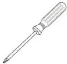
Line drawing of a screwdriver with a flat blade and handle (no text or symbols)Tournevis Phillips (cruciforme)
natural_image
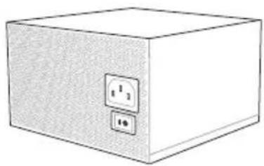
Simple line drawing of a box with two electrical outlets (no text or symbols)Bloc d'alimentation
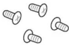
1 sachet de vis
natural_image
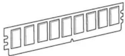
Line drawing of a 12-pin RAM module (no text or symbols)Module(s) de mïmoire
natural_image
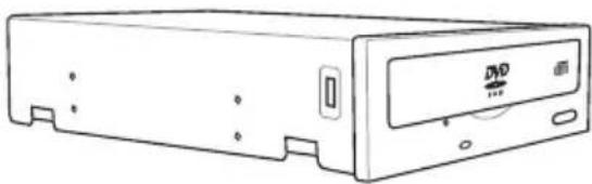
Line drawing of a rectangular electronic device with a DVD drive and ventilation slots (no text or symbols)natural_image
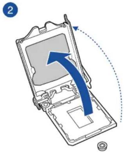
Technical line drawing of a mechanical component with no visible text or symbolsROG STRIX B365-G GAMING CPU LGA1151

ROG STRIX B365-G GAMING 288-pin DDR4 DIMM socket

ROG STRIX B365-G GAMING Clear RTC RAM jumper
ROG STRIX B365-G GAMING Fan and Pump connectors

ROG STRIX B365-G GAMING System panel connector
natural_image
Hand holding a device with a red X mark, no visible text or symbols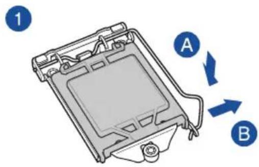
natural_image
Diagram of a device interior with a blue arrow indicating direction, showing internal components and a dotted arc (no text or symbols)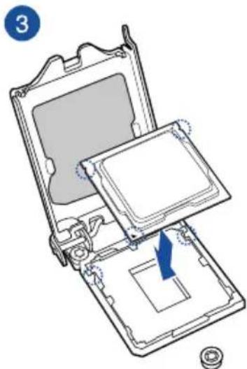
natural_image
Diagram of an open computer case with a blue arrow indicating a component, showing internal components and a circular base (no text or symbols)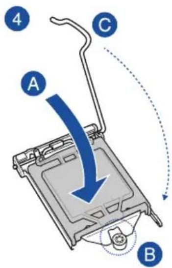
natural_image
Exploded view diagram of a computer processor showing internal components and directional arrows (no text or symbols)natural_image
Technical line drawing of a mechanical assembly with a spring and warning symbol (no text or labels)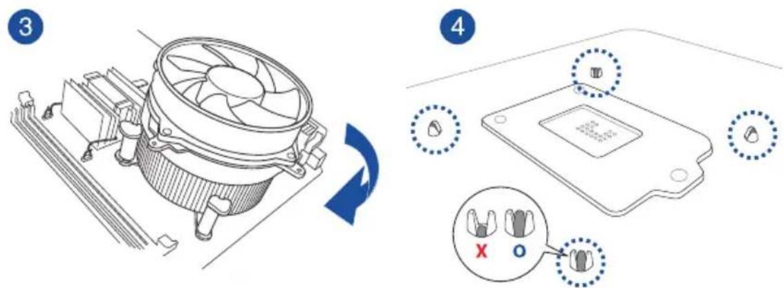
natural_image
Diagram of a computer motherboard showing CPU socket, fan, and heatsink (no text or labels)natural_image
Technical diagram of a mechanical assembly with a screwdriver inserted, showing internal components and no visible text or symbols.

natural_image
Technical illustration of a mechanical component with labeled parts A and B, showing internal structure and motion indicators (no text or symbols beyond labels)natural_image
Technical diagram of a computer monitor internal structure with no visible text or symbolsCarte PCIe x1
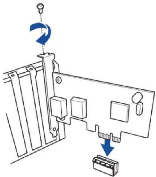
natural_image
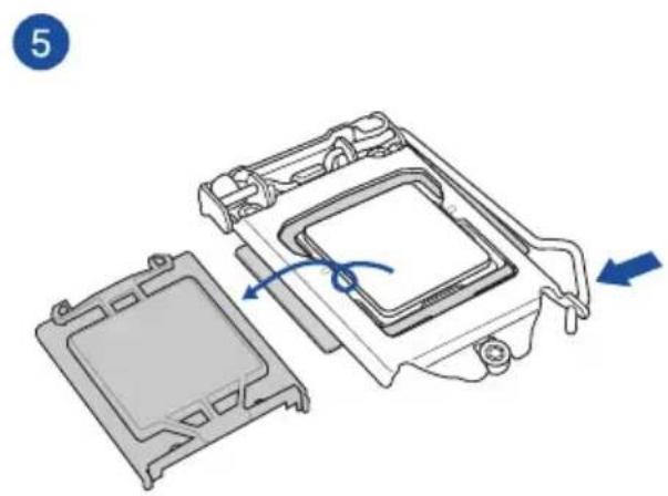
Diagram of a computer monitor with labeled ports and directional arrows indicating motion (no text or symbols present)
natural_image
Diagram of an electronic component with a blue arrow pointing to a circuit board layout (no text or symbols present)
natural_image
Diagram showing audio recording setup with headphones, a handheld device, and connected cables (no text or labels)Assistant EZ Tuning (F11)
Barre de dïfilement
3.2.4 Assistant EZ Tuning

PCI Express Configuration (Configuration PCI Express)
SATA Mode Selection (Sïlection de mode SATA)
[Intel RST Premium With Intel Optane System Acceleration(RAID)]
SMART Self Test (Auto-test SMART)
RGB LED lighting (Йclairage LED RGB)
CSM (Compatibility Support Module)

Discard Changes and Exit (Annuler et quitter)
| Code Description | |
| 00 | Not used |
| 01 | Power on. Reset type detection (soft/hard). |
| 02 | AP initialization before microcode loading |
| 03 | System Agent initialization before microcode loading |
| 04 | PCH initialization before microcode loading |
| 06 | Microcode loading |
| 07 | AP initialization after microcode loading |
| 08 | System Agent initialization after microcode loading |
| 09 | PCH initialization after microcode loading |
| 0B | Cache initialization |
| 0C-0D | Reserved for future AMI SEC error codes |
| 0E | Microcode not found |
| 0F | Microcode not loaded |
| 10 | PEI Core is started |
| 11-14 | Pre-memory CPU initialization is started |
| 15-18 | Pre-memory System Agent initialization is started |
| 19-1C | Pre-memory PCH initialization is started |
| 2B-2F | Memory initialization |
| 30 | Reserved for ASL (see ASL Status Codes section below) |
| 31 | Memory Installed |
| 32-36 | CPU post-memory initialization |
| 37-3A | Post-Memory System Agent initialization is started |
| 3B-3E | Post-Memory PCH initialization is started |
| 4F | DXE IPL is started |
| 50-53 | Memory initialization error. Invalid memory type or incompatible memory speed |
| 54 | Unspecified memory initialization error |
| 55 | Memory not installed |
| 56 | Invalid CPU type or Speed |
| 57 | CPU mismatch |
| 58 | CPU self test failed or possible CPU cache error |
| 59 | CPU micro-code is not found or micro-code update is failed |
| 5A | Internal CPU error |
| 5B | Reset PPI is not available |
| 5C-5F | Reserved for future AMI error codes |
| Code Description | |
| E0 | S3 Resume is stared (S3 Resume PPI is called by the DXE IPL) |
| E1 | S3 Boot Script execution |
| E2 | Video repost |
| E3 | OS S3 wake vector call |
| E4 – E7 | Reserved for future AMI progress codes |
| E8 | S3 Resume Failed |
| E9 | S3 Resume PPI not Found |
| EA | S3 Resume Boot Script Error |
| EB | S3 OS Wake Error |
| EC – EF | Reserved for future AMI error codes |
| F0 | Recovery condition triggered by firmware (Auto recovery) |
| F1 | Recovery condition triggered by user (Forced recovery) |
| F2 | Recovery process started |
| F3 | Recovery firmware image is found |
| F4 | Recovery firmware image is loaded |
| F5 – F7 | Reserved for future AMI progress codes |
| F8 | Recovery PPI is not available |
| F9 | Recovery capsule is not found |
| FA | Invalid recovery capsule |
| FB – FF | Reserved for future AMI error codes |
| 60 | DXE Core is started |
| 61 | NVRAM initialization |
| 62 | Installation of the PCH Runtime Services |
| 63 – 67 | CPU DXE initialization is started |
| 68 | PCI host bridge initialization |
| 69 | System Agent DXE initialization is started |
| 6A | System Agent DXE SMM initialization is started |
| 6B – 6F | System Agent DXE initialization (System Agent module specific) |
| 70 | PCH DXE initialization is started |
| 71 | PCH DXE SMM initialization is started |
| 72 | PCH devices initialization |
| 73 – 77 | PCH DXE Initialization (PCH module specific) |
| 78 | ACPI module initialization |
| 79 | CSM initialization |
| 7A – 7F | Reserved for future AMI DXE codes |
| Code Description | |
| 90 | Boot Device Selection (BDS) phase is started |
| 91 | Driver connecting is started |
| 92 | PCI Bus initialization is started |
| 93 | PCI Bus Hot Plug Controller Initialization |
| 94 | PCI Bus Enumeration |
| 95 | PCI Bus Request Resources |
| 96 | PCI Bus Assign Resources |
| 97 | Console Output devices connect |
| 98 | Console input devices connect |
| 99 | Super IO Initialization |
| 9A | USB initialization is started |
| 9B | USB Reset |
| 9C | USB Detect |
| 9D | USB Enable |
| 9E – 9F | Reserved for future AMI codes |
| A0 | IDE initialization is started |
| A1 | IDE Reset |
| A2 | IDE Detect |
| A3 | IDE Enable |
| A4 | SCSI initialization is started |
| A5 | SCSI Reset |
| A6 | SCSI Detect |
| A7 | SCSI Enable |
| A8 | Setup Verifying Password |
| A9 | Start of Setup |
| AA | Reserved for ASL (see ASL Status Codes section below) |
| AB | Setup Input Wait |
| AC | Reserved for ASL (see ASL Status Codes section below) |
| AD | Ready To Boot event |
| AE | Legacy Boot event |
| AF | Exit Boot Services event |
| B0 | Runtime Set Virtual Address MAP Begin |
| B1 | Runtime Set Virtual Address MAP End |
| B2 | Legacy Option ROM Initialization |
| B3 | System Reset |
| Code Description | |
| B4 | USB hot plug |
| B5 | PCI bus hot plug |
| B6 | Clean-up of NVRAM |
| B7 | Configuration Reset (reset of NVRAM settings) |
| B8– BF | Reserved for future AMI codes |
| D0 | CPU initialization error |
| D1 | System Agent initialization error |
| D2 | PCH initialization error |
| D3 | Some of the Architectural Protocols are not available |
| D4 | PCI resource allocation error. Out of Resources |
| D5 | No Space for Legacy Option ROM |
| D6 | No Console Output Devices are found |
| D7 | No Console Input Devices are found |
| D8 | Invalid password |
| D9 | Error loading Boot Option (LoadImage returned error) |
| DA | Boot Option is failed (StartImage returned error) |
| DB | Flash update is failed |
| DC | Reset protocol is not available |
ACPI/ASL Checkpoints (under OS)
| Code Description | |
| 03 | System is entering S3 sleep state |
| 04 | System is entering S4 sleep state |
| 05 | System is entering S5 sleep state |
| 30 | System is waking up from the S3 sleep state |
| 40 | System is waking up from the S4 sleep state |
| AC | System has transitioned into ACPI mode. Interrupt controller is in PIC mode. |
| AA | System has transitioned into ACPI mode. Interrupt controller is in APIC mode. |
Notices
English ASUSTeK Computer Inc. hereby declares that this device is in compliance with the essential requirements and other relevant provisions of related Directives. Full text of EU declaration of conformity is available at: www.asus.com/support
www.asus.com/support
Hrvatski ASUSTeK Computer Inc. ovim izjavljuje da je ovaj uredaj sukladan s bitnim zahtjevima i ostalim odgovarajućim odredbama vezanih direktiva. Cijeli tekst EU izjave o sukladnosti dostupan je na: www.asus.com/support
www.asus.com/support
Dansk ASUSTeK Computer Inc. erklærer hermed, at denne enhed er i overensstemmelse med hovedkravene og andre relevante bestemmelser i de relaterede direktiver. Hele EU-overensstemmelseserklæringen kan findes på:
www.asus.com/support
Adresse 4F, No. 150, Li-Te Road, Peitou, Taipei 112, Taiwan
Téléphone +886-2-2894-3447
Fax +886-2-2890-7798
Site Web www.asus.com
Support technique
Téléphone +86-21-38429911
Fax +86-21-5866-8722, ext. 9101#
Support en ligne http://qr.asus.com/techserv
ASUS COMPUTER INTERNATIONAL (Amïrique)
Adresse 48720 Kato Rd., Fremont, CA 94538, USA
Téléphone +1-510-739-3777
Fax +1-510-608-4555
Site Web http://www.asus.com/us/
Support technique
Support fax +1-812-284-0883
Téléphone +1-812-282-2787
Support en ligne http://qr.asus.com/techserv
Adresse Harkort Str. 21-23, 40880 Ratingen, Germany
Fax +49-2102-959931
Site Web http://www.asus.com/de