
TL053700AV - Pneumatic grease gun Campbell Hausfeld - Free user manual and instructions
Find the device manual for free TL053700AV Campbell Hausfeld in PDF.

| Product Type | Pneumatic Grease Gun |
| Brand | Campbell Hausfeld |
| Model | TL053700AV |
| Average Air Consumption | 2.8 L/min at 621 kPa |
| Operating Pressure | 621 kPa |
| Air Inlet Size | 6.4 mm (1/4 in) Female NPT |
| Filling Method | 414 mL (14 oz) cartridge or bulk fill |
| Reservoir Capacity | 0.41 L |
| Tool Weight | 1.45 kg |
| Grease Hose Length | 22.86 cm (9 in) |
| Recommended Lubrication | Campbell Hausfeld pneumatic tool oil ref. ST1270 |
| Piston Lubrication | Every 4 months (heavy use) or 1 year (light use) with bearing grease |
| Maximum Air Pressure | 621 kPa (do not exceed) |
| Connections | Female 6.4 mm NPT coupler, male 6.4 mm NPT plug |
| Minimum Compressor | 3.79 L (1 gal) |
| Maintenance | Clean regularly, check for air leaks |
| Safety | Wear safety glasses, disconnect before maintenance |
| Priming | Fill the grease inlet port before first use |
| Air Bleeding | Use the air bleeder to remove air pockets |
| Warranty | 1 year (domestic use), 90 days (commercial use) |
| Replacement Parts | Available at campbellhausfeld.com |
Frequently Asked Questions - TL053700AV Campbell Hausfeld
User questions about TL053700AV Campbell Hausfeld
0 question about this device. Answer the ones you know or ask your own.
Ask a new question about this device
Download the instructions for your Pneumatic grease gun in PDF format for free! Find your manual TL053700AV - Campbell Hausfeld and take your electronic device back in hand. On this page are published all the documents necessary for the use of your device. TL053700AV by Campbell Hausfeld.
USER MANUAL TL053700AV Campbell Hausfeld
CH CAMPBELL HAUSFELD.
Air-operated Grease Gun
Operating Instructions
natural_image
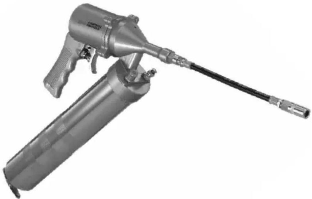
Metal spray gun with attached probe, shown in grayscale (no text or symbols visible)Models: TL053700AV and TL053700DI
Please read and save these instructions. Read carefully before attempting to assemble, install, operate or maintain the product described.
Protect yourself and others by observing all safety information. Failure to comply with instructions could result in personal injury and/or property damage! Retain instructions for future reference.
REMINDER: Keep your dated proof of purchase for warranty purposes! Attach it to this manual or file it for safekeeping.
Model #: ____
Serial #: ____
Purchase Date: ____
For parts, product & service information visit www.campbellhausfeld.com
Campbell Hausfeld
100 Production Drive
Harrison, Ohio 45030
BEFORE YOU BEGIN
Description
Air-operated grease guns are designed for lubricating automobiles, recreational vehicles, machinery and lawn/farm equipment in shots—this tool does NOT apply grease in a continuous flow. The container tube is capable of dispensing bulk-filled or 14 ounce grease cartridges. A 9 inch flexible hose allows access to hard to reach fittings.
UNPACKING
After unpacking the unit, inspect carefully for any damage that may have occurred during transit. Check for loose, missing or damaged parts. Check to be sure all supplied accessories are enclosed with the unit. In case of questions, damaged or missing parts, please visit www.campbellhausfeld.com for customer assistance.
Do not operate with WARNING
if damaged during shipping, handling or use. Damage may result in bursting and
cause injury or property damage.
Other Parts (Not Provided)
You will need the following items and/or accessories to properly set-up and use this air-operated grease gun:
• 1/4 in. Plug NPT (M)
- For less stress on your air hose and you, try a flex plug.
• 1/4 in. (ID) Air Hose
• 1/4 in. Coupler NPT (F)
- Eliminate coupler confusion with a universal coupler style.
- Quick-connect couplers quickly, easily join hoses to tools.
- If you don't use a flex plug, consider a swivel coupler to prevent hose kinks and reduce stress on your air hose.
• 1 Gallon air compressor or larger
• 14 Ounce grease cartridge or bulk grease
- Adjustable wrench and PTFE tape to ensure tight connections
See www.campbellhausfeld.com for additional information on accessories to support your air tools and pneumatic system.
SPECIFICATIONS
TL0537
Average Air Consumption 0.1 CFM @ 90 PSI
Operating Pressure 90 PSI
Air Inlet Size 1/4 inch NPT
Fill Method Cartridge or Bulk-Filled
Cartridge Size 14 ounces
Tool Weight 3 lbs. 3 oz.
DIMENSIONS
Dimensions (assembled air tool, without grease hose attached)
Length 6-1/2 in.
Width 2-3/8 in.
Height 15-1/4 in.
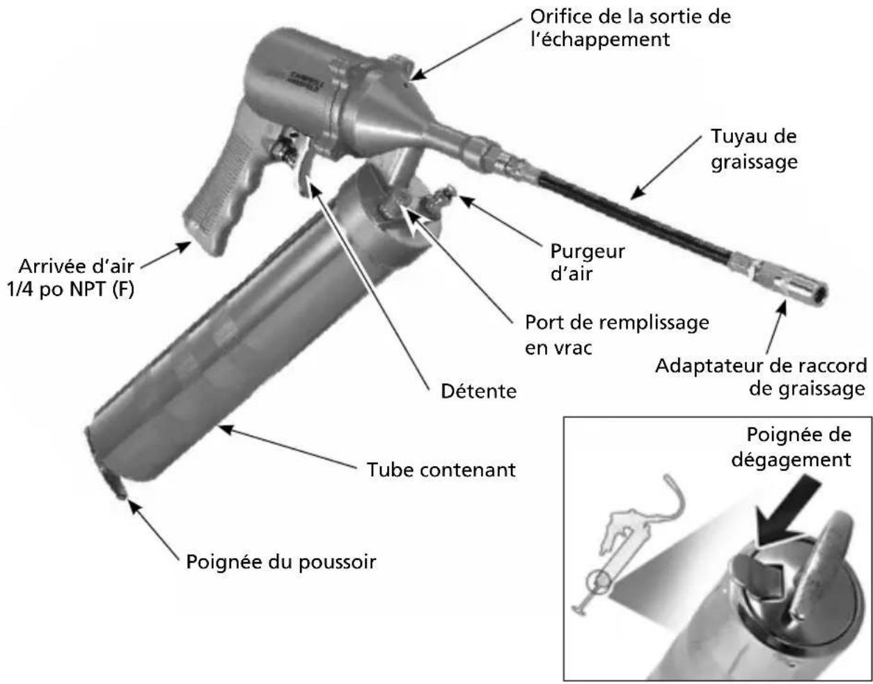
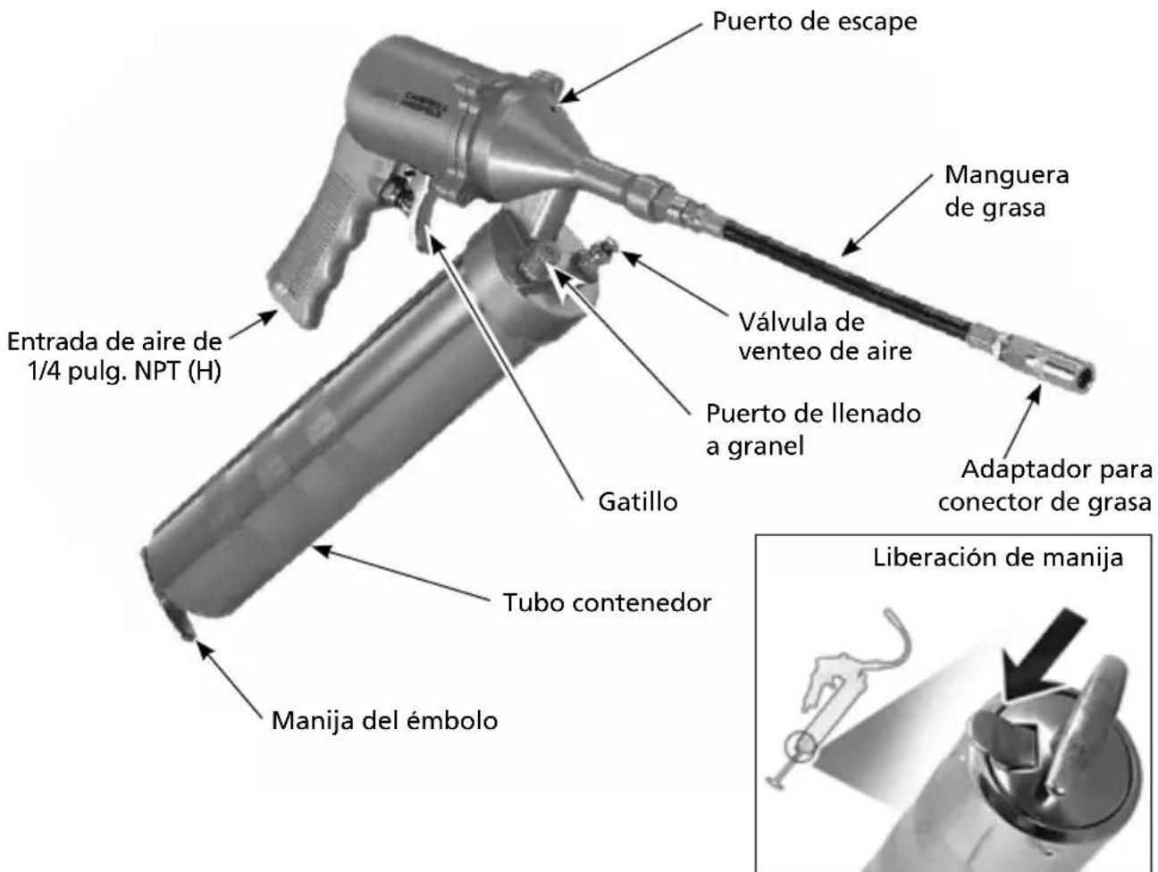
GETTING TO KNOW YOUR UNIT
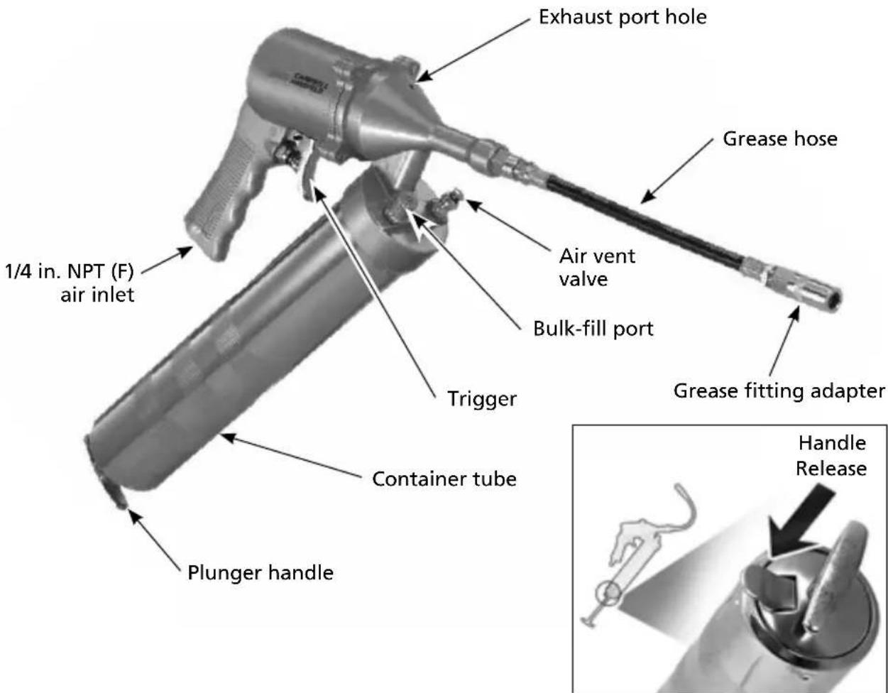
Figure 1
ASSEMBLY INSTRUCTIONS
Your grease gun comes from the manufacturer in 3 pieces. Unwrap each piece from their protective poly bag. Thread the grease hose into the inlet port of the grease gun and tighten. To prevent grease from seeping between grease hose and grease gun, use PTFE tape and an adjustable wrench to ensure a leak-proof connection.
Determine the method you will be using to fill the grease container tube from the OPERATING INSTRUCTIONS below.
OPERATING INSTRUCTIONS
Fill container tube with grease using one of the 3 methods described below.
Grease Cartridges:
- Unscrew the grease gun from the container tube.
- Pull the plunger handle back and out of the container tube as far as it will go.
-
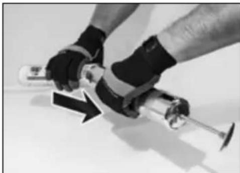
Insert the open end of a 14 ounce grease cartridge into the container tube and push the cartridge completely in to the container tube.
-
Remove the seal from the grease cartridge.
natural_image
Close-up of a person using a mechanical tool with a black arrow indicating motion (no text or symbols visible)Figure 2
-
Thread the grease gun and container tube back together and turn until tight.
-
Press the handle release down to activate the plunger handle rod and push the plunger handle back into the container tube.
-
Press the air vent valve several times to relieve any air pockets near the top of the container tube.
Filler-Pump Method:
- Thread the container tube on to the grease gun and turn until tight.
- Pull the plunger handle back and out of the container tube as far as it will go.
- Connect the filler-pump hose to the bulk-fill port.
- Pump grease in to the container tube until filled; disconnect the grease gun from the filler-pump hose.
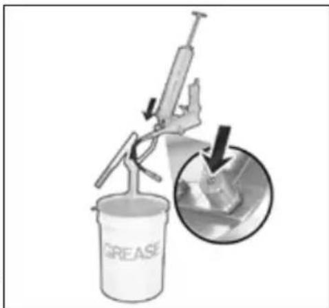
Figure 3
-
Press the handle release tab down to Figure 3 activate the plunger handle rod and push the plunger handle back into the container tube.
-
Press the air vent valve several times to relieve any air pockets near the top of the container tube.
OPERATING INSTRUCTIONS (CONTINUED)
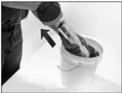
Bulk-Filled Grease:
- Unscrew the grease gun from the container tube.
- Insert open end of container tube in to grease bucket (fully submerging the opening).
- Pull the plunger handle back to suck grease in to the container tube. Pull slowly and with consistent force to ensure that the container tube is full of grease by the time the plunger handle is fully extended.
natural_image
Person pouring liquid into a bucket with an arrow indicating direction (no text or symbols)Figure 4
- Thread the grease gun and container tube back together and turn until tight.
- Press the handle release tab down to activate the plunger handle rod and push the plunger handle back into the container tube.
- Press the air vent valve several times to relieve any air pockets near the top of the container tube.
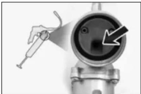
TIP: For best results, consider priming grease gun before first use. To do this, pack some grease in to the grease inlet port of the gun, then operate as usual. (See arrow in Figure 5.)
Connect grease gun to air compressor system following Air Tool Set Up Instructions (IN170102AV).
natural_image
Close-up of a mechanical component with a hand holding a tool and a circular opening, showing a black arrow pointing to a hole (no text or symbols visible)Figure 5 - Grease inlet port
CARE & MAINTENANCE
Failure to lubricate and maintain your air tools properly will dramatically shorten their life. Use "air tool" oil every time you use your grease gun to lubricate, clean and inhibit rust in one step. Campbell Hausfeld sells air tool oil under part number ST1270.
In addition to regular lubrication of your air tool, the grease gun piston must be lubricated periodically. Under heavy usage, the piston should be greased with bearing grease every four months. For light usage only once a year.
To grease the piston:
- Disconnect the tool from the air supply.
- Remove the 4 screws on the gun head.
- Separate the gun head from the pistol grip and remove the spring and the piston.
- Apply a film of bearing grease around the exterior of the rubber skirt on the piston and a thin film of grease on the inside of the cylinder.
- Install the spring and piston and reassemble the gun head and the pistol grip. Insert and tighten 4 screws.
GENERAL SAFETY INSTRUCTIONS
This manual contains information that is very important to know and understand. This information is provided for SAFETY and to PREVENT EQUIPMENT PROBLEMS. To help recognize this information, observe the symbols found on page 7. The Safety Symbols throughout this manual are to alert you to important safety hazards and precautions.
The DANGER, WARNING, CAUTION, and NOTICE notifications and instructions in this manual cannot cover all possible conditions and situations that may occur. It must be understood by the operator that caution is a factor which cannot be built into this product, but must be supplied by the operator.
With any piece of equipment, new or used, the most important part of its operation is SAFETY!
Campbell Hausfeld encourages you to familiarize yourself with your new equipment and stresses safe operation.
The next few pages of this manual are a summary of the main safety aspects associated with this unit. Be sure to read and understand completely before operating the machine.
The symbols used throughout the operation and maintenance sections of this manual call attention to safety procedures.
Important Safety Information

Please read and save these instructions. Read carefully before attempting to assemble, install, operate or maintain the product described. Protect yourself and others by observing all safety information. Failure to comply with instructions could result in personal injury and/or property damage! Retain instructions for future reference.
This manual contains important safety, operational and maintenance information. If you have any questions, please visit www.campbellhausfeld.com for customer assistance.
California Proposition 65

- This product or its power cord may contain chemicals known to the State of California to cause cancer and birth defects or other reproductive harm. Wash hands after handling.
GENERAL SAFETY INSTRUCTIONS (CONTINUED)
General Safety
This product is part of a high pressure system and the following safety precautions must be followed at all times along with any other existing safety rules.
- Read all manuals included with this product carefully. Be thoroughly familiar with the controls and the proper use of the equipment.
- Only persons well acquainted with these rules of safe operation should be allowed to use the air tool.

maximum operating pressure of the air tool (90 psi). This can reduce the life of the tool.
-
Do not exceed any pressure rating of any component in the system.
-
Disconnect air tool from air supply before changing tools or attachments, servicing and during non-operation.

Safety glasses must be worn during operation.
- Do not wear loose fitting clothing, scarves, neck ties or jewelry when operating any tool. Loose clothing or jewelry may become caught in moving parts and result in serious personal injury.
- Do not depress trigger when connecting the air supply hose.
- Always use attachments designed for use with air powered tools. Do not use damaged or worn attachments.
- Never trigger tool when not applied to a work object. Attachments must be securely attached. Loose attachments can cause serious injury.
- Protect air lines from damage or puncture.
- Never point an air tool at oneself or any other person. Serious injury could occur.
- Check air hoses for weak or worn condition before each use. Make sure all connections are secure.

from the system before attempting to install, service, relocate or perform
-
Keep all nuts, bolts and screws tight and ensure equipment is in safe working condition.
-
Do not put hands near or under moving parts.
-
Always secure work.

to vibration, working in awkward positions and repetitive work motions can
cause injury to hands and arms. Stop using any tool if discomfort, numbness, tingling or pain occur and consult a physician.

y the hose or pull the hose to move the tool or a compressor. Keep hoses away
from heat, oil and sharp edges. Replace any hose that is damaged, weak or worn.
Safety Glossary
This manual contains information that is very important to know and understand. This information is provided for SAFETY and to PREVENT EQUIPMENT PROBLEMS. To help recognize this information, observe the following symbols.

imminently hazardous situation which, if not avoided, WILL result in death or serious injury.

potentially hazardous situation which, if not avoided, COULD result in death or
serious injury.

potentially hazardous situation which, if not avoided, MAY result in minor or
moderate injury.

portant information, that if not followed, may cause damage to equipment.
IMPORTANT or NOTE: Information that requires special attention.
Safety Symbols
The following Safety Symbols appear throughout this manual to alert you to important safety hazards and precautions.

Read Manual
First
Wear eye and hearing protection
Risk of
Pressure
SAVE THESE INSTRUCTIONS DO NOT DISCARD
SYMPTOM POSSIBLE CAUSE(S) CORRECTIVE ACTION
| Tool will not operate 1. | No grease in tool 1. Lubricate the tool according tothe lubrication instructions in this manual.2. Low air pressure 2. Adjust the compressor regulator asneeded.3. Air hose leaks 3. Tighten and seal hose fittings if leaksare found. | |
| Tool operates, butgrease will not ejectfrom spout | 1. Cold, thick grease 1. Bring tool inside and warm to roomtemperature of 70^ - 85^ . Stand thegun in an upright position to preventair pockets forming in the middle ofthe cartridge.2. Spring is still compressed 2. Pull the plunger handle back andrelease quickly. Make sure the catchplate is released.3. Out of grease 3. Refill container tube.4. Air pockets in container tube 4. Remove air pockets (See below). | |
| Grease stops flowingafter initially working | Air in the grease hose orcontainer tube | 1. Remove air pockets from grease gun:a. Partially unscrew the greasegun from the container tube(approximately 1 to 1-1/2 turns).b. Pull the plunger handle backand release it quickly by pressingdown on the handle release tab.Repeat several times.v. Release the handle release downand tighten the grease gun andcontainer tube again.d. Press the air vent valve severaltimes to relieve any air pocketsnear the top of the containertube.e. When the grease gun containertube has been properly bleed ofair, grease will start to seep outof the air vent valve.2. Prime grease gun by packing greasein to the grease inlet port of thegun (this is the section of the gun inwhich the container tube threads). |
NOTES:
Reminder: Keep your dated proof of purchase for warranty purposes! Attach it to this manual or file it for safekeeping.
LIMITED WARRANTY
- DURATION: From the date of purchase by the original purchaser as follows: One (1) Year.
- WHO GIVES THIS WARRANTY (WARRANTOR): Campbell Hausfeld a Marmon/Berkshire Hathaway Company, 100 Production Drive, Harrison, Ohio, 45030. Visit www.campbellhausfeld.com
- WHO RECEIVES THIS WARRANTY (PURCHASER): The original purchaser (other than for purposes of resale) of the Campbell Hausfeld product.
- WHAT PRODUCTS ARE COVERED BY THIS WARRANTY: Any Campbell Hausfeld nailer, stapler, air tool, spray gun, inflator or air accessory supplied or manufactured by Warrantor.
-
WHAT IS COVERED UNDER THIS WARRANTY: Substantial defects in material and workmanship which occur within the duration of the warranty period.
-
WHAT IS NOT COVERED UNDER THIS WARRANTY:
A. Implied warranties, including those of merchantability and FITNESS FOR A PARTICULAR PURPOSE ARE LIMITED FROM THE DATE OF ORIGINAL PURCHASE AS STATED IN THE DURATION. If this product is used for commercial, industrial or rental purposes, the warranty will apply for ninety (90) days from the date of purchase. Some States do not allow limitation on how long an implied warranty lasts, so the above limitations may not apply to you.
B. ANY INCIDENTAL, INDIRECT, OR CONSEQUENTIAL LOSS, DAMAGE, OR EXPENSE THAT MAY RESULT FROM ANY DEFECT, FAILURE, OR MALFUNCTION OF THE CAMPBELL HAUSFELD PRODUCT. Some States do not allow the exclusion or limitation of incidental or consequential damages, so the above limitation or exclusion may not apply to you.
C. Any failure that results from an accident, purchaser's abuse, neglect or failure to operate products in accordance with instructions provided in the owner's manual(s) supplied with product. Accident, purchaser's abuse, neglect or failure to operate products in accordance with instructions shall also include the removal or alteration of any safety devices. If such safety devices are removed or altered, this warranty is void.
D. Normal adjustments which are explained in the owner's manual(s) provided with the product.
E. Items or service that are normally required to maintain the product, i.e. o-rings, springs, bumpers, debris shields, driver blades, fuses, batteries, gaskets, packings or seals, fluid nozzles, needles, sandblast nozzles, lubricants, material hoses, filter elements, motor vanes, abrasives, blades, cut-off wheels, chisels, chisel retainers, cutters, collets, chucks, rivet jaws, screw driver bits, sanding pads, back-up pads, impact mechanism, or any other expendable part not specifically listed. These items will only be covered for ninety (90) days from date of original purchase. Underlined items are warranted for defects in material and workmanship only.
-
RESPONSIBILITIES OF WARRANTY: Repair or replace, at Warrantor's option, products or components which are defective, have malfunctioned and/or failed to conform within duration of the warranty period.
-
RESPONSIBILITIES OF PURCHASER UNDER THIS WARRANTY:
A. Provide dated proof of purchase and maintenance records.
B. Deliver or ship the Campbell Hausfeld product or component to the nearest Campbell Hausfeld Authorized Service Center. Freight costs, if any, must be borne by the purchaser.
C. Use reasonable care in the operation and maintenance of the products as described in the owner's manual(s).
- WHEN WARRANTOR WILL PERFORM REPAIR OR REPLACEMENT UNDER THIS WARRANTY: Repair or replacement will be scheduled and serviced according to the normal work flow at the servicing location, and depending on the availability of replacement parts.
This Limited Warranty applies in the United States, Canada and Mexico only and gives you specific legal rights. You may also have other rights which vary from state to state or country to country.
CH CAMPBELL HAUSFELD.
natural_image
Metal spray gun with attached probe, shown in grayscale (no text or symbols visible)| Dimensions (assembled air tool, without grease hose attached) |
| Leng. 16,51 cm |
| Larg. 8,57 cm |
| Haut. 38,74 cm |
APPRENEZ À CONNAÎTRE VOTRE UNITÉ
natural_image
Close-up of a person using a mechanical tool with a black arrow indicating motion (no text or symbols visible)Figure 2
natural_image
Person pouring liquid into a bucket with an arrow indicating direction (no text or symbols visible)Figure 4
natural_image
Close-up of a mechanical component with a hand holding a syringe and a circular dial, showing a black arrow pointing to a square hole (no text or symbols visible)CH CAMPBELL HAUSFELD.
natural_image
Metal spray gun with attached probe, shown in grayscale (no text or symbols visible)Modelos: TL053700AV y TL053700DI
Harrison, Ohio 45030
ANTES DE COMENZAR
Descripción
Dimensions (assembled air tool, without grease hose attached)
Long. 16,51 cm
Anch. 8,57 cm
Alt. 38,74 cm
CONOZCA SU UNIDAD
natural_image
Close-up of hands using a mechanical tool with a black arrow indicating motion (no text or symbols visible)Figura 2
natural_image
Person pouring liquid into a bucket with an arrow indicating direction (no text or symbols visible)Figura 4
natural_image
Close-up of a mechanical component with a hand holding a tool, showing internal components and a downward arrow (no text or symbols)Figura 5 - Puerto de entrada de grasa


- CH CAMPBELL HAUSFELD.
- Air-operated Grease Gun
- BEFORE YOU BEGIN
- Description
- UNPACKING
- Do not operate with WARNING
- Other Parts (Not Provided)
- SPECIFICATIONS
- TL0537
- DIMENSIONS
- Dimensions (assembled air tool, without grease hose attached)
- GETTING TO KNOW YOUR UNIT
- ASSEMBLY INSTRUCTIONS
- OPERATING INSTRUCTIONS
- Grease Cartridges:
- Filler-Pump Method:
- OPERATING INSTRUCTIONS (CONTINUED)
- Bulk-Filled Grease:
- CARE & MAINTENANCE
- GENERAL SAFETY INSTRUCTIONS
- Important Safety Information
- California Proposition 65
- GENERAL SAFETY INSTRUCTIONS (CONTINUED)
- General Safety
- Safety glasses must be worn during operation.
- Safety Glossary
- Safety Symbols
- SAVE THESE INSTRUCTIONS DO NOT DISCARD
- NOTES:
- LIMITED WARRANTY
- ANTES DE COMENZAR
- Descripción
- CONOZCA SU UNIDAD
Brand : Campbell Hausfeld
Model : TL053700AV
Category : Pneumatic grease gun