
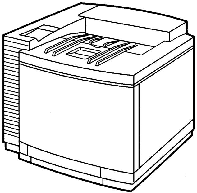
HL-2400CEN - Color laser printer BROTHER - Free user manual and instructions
Find the device manual for free HL-2400CEN BROTHER in PDF.

| Product type | Color laser printer |
| Brand | Brother |
| Model | HL-2400CEN |
| Dimensions (W x D x H) | Approx. 540 x 560 x 450 mm |
| Weight | Approx. 35 kg |
| Power supply | 220-240 V AC, 50/60 Hz |
| Power consumption (standby) | Less than 100 W |
| Duplex printing | Automatic |
| Print resolution | Up to 600 x 600 dpi |
| Print speed (color) | Up to 24 ppm |
| Paper tray capacity | 500 sheets (standard) |
| Printer languages | PCL 6, PostScript 3 |
| Connectivity | Ethernet, USB 2.0, Parallel |
| Noise level (printing) | Less than 55 dB(A) |
| Maintenance and cleaning | Clean the drum and rollers with a lint-free cloth; use a maintenance kit |
| Safety | Compliant with CE, FCC Class B; use a grounded outlet |
| Spare parts and repairability | Toner cartridges, drum, waste bin; repairability score 8/10 |
| General information | User manual available in PDF; Brother online support |
Frequently Asked Questions - HL-2400CEN BROTHER
User questions about HL-2400CEN BROTHER
0 question about this device. Answer the ones you know or ask your own.
Ask a new question about this device
Download the instructions for your Color laser printer in PDF format for free! Find your manual HL-2400CEN - BROTHER and take your electronic device back in hand. On this page are published all the documents necessary for the use of your device. HL-2400CEN by BROTHER.
USER MANUAL HL-2400CEN BROTHER
Brother Color Laser Printer
HL-2400Ce series
USER'S GUIDE
natural_image
Line drawing of a mechanical device with internal components (no text or symbols)Please read this manual thoroughly before using the printer. Keep this manual in a convenient place for quick reference at all times.
Trademarks
Brother is a registered trademark of Brother Industries, Ltd.
Apple and LaserWriter are registered trademarks, and TrueType is a trademark of Apple Computer, Inc.
Centronics is a trademark of Genicom Corporation.
EPSON is a registered trademark, and FX-850 and FX-80 are trademarks of Seiko Epson Corporation.
Hewlett-Packard, HP, PCL5C, PCL5e, PCL6 and PCL are registered trademarks, and HP LaserJet 5, HP LaserJet 4+, HP LaserJet Plus, HP LaserJet II, HP LaserJet IID, HP LaserJet IIID, HP-GL, HP-GL/2, and Bi-Tronics are trademarks of Hewlett-Packard Company.
IBM, Proprinter XL, Proprinter, and IBM/PC are registered trademarks of International Business Machines Corporation.
Intellifont is a registered trademark of AGFA Corporation, a division of Miles, Inc. Microsoft and MS-DOS are registered trademarks of Microsoft Corporation.
Windows is a registered trademark of Microsoft Corporation in the United States and other countries.
PostScript is a registered trademark of Adobe Systems Incorporated.
All trademarks noted herein are either the property of Brother Industries, Ltd.,
ENERGY STAR is a U.S. registered mark.
All other brand and product names mentioned in this user's guide are registered trademarks or trademarks of respective companies.
Compilation and Publication
Under the supervision of Brother Industries Ltd., this manual has been compiled and published, covering the latest product descriptions and specifications.
The contents of this manual and the specifications of this product are subject to change without notice.
Brother reserves the right to make changes without notice in the specifications and materials contained herein and shall not be responsible for any damages (including consequential) caused by reliance on the materials presented, including but not limited to typographical and other errors relating to the publication.
©2000 Brother Industries Ltd.
Shipment of the Printer
If for any reason you must ship your Printer, carefully package the Printer to avoid any damage during transit. It is recommended that you save and use the original packaging. The Printer should also be adequately insured with the carrier.
WARNING
When shipping the Printer, the TONER CARTRIDGES and ALL CONSUMABLES must be removed from the Printer. Failure to remove the CONSUMABLES during shipping will cause severe damage to the Printer and will VOID THE WARRANTY (refer to user's manual).
(For USA & CANADA Only)
For technical and operational assistance, please call:
In USA 1-877-284-3238
In CANADA 1-800-853-6660
514-685-6464 (within Montreal)
If you have comments or suggestions, please write us at:
In USA Printer Customer Support
Brother International Corporation
15 Musick
Irvine, CA 92618
In CANADA Brother International Corporation (Canada), Ltd.
- Marketing Dept.
For downloading drivers from our Bulletin Board Service, call:
In USA 1-888-298-3616
In CANADA 1-514-685-2040
Please log on to our BBS with your first name, last name and a four digit number for your password. Our BBS supports modem speeds up to 14,400,8 bits no parity, 1 stop bit.
Fax-Back System
Brother Customer Service has installed an easy to use Fax-Back System so you can get instant answers to common technical questions and product information for all Brother products. This is available 24 hours a day, 7 days a week. You can use the system to send the information to any fax machine, not just the one you are calling from.
Please call 1-800-521-2846 (USA) or 1-800-681-9838 (Canada) and follow the voice prompts to receive faxed instructions on how to use the system and your index of Fax-Back subjects.
DEALERS/SERVICE CENTERS (USA only)
For the name of an authorized dealer or service center, call 1-800-284-4357.
SERVICE CENTERS (Canada only)
For service center addresses in Canada, call 1-800-853-6660
INTERNET ADDRESS
For technical questions and downloading drivers : http://www.brother.com
brother®
(For USA & CANADA Only)
For technical and operational assistance, please call:
In USA 1-877-284-3238
In CANADA 1-800-853-6660
514-685-6464 (within Montreal)
If you have comments or suggestions, please write us at:
| In USA | Printer Customer SupportBrother International Corporation15 MusickIrvine, CA 92618 |
| In CANADA | Brother International Corporation (Canada), Ltd.- Marketing Dept.1, rue Hôtel de VilleDollard-des-Ormeaux, PQ, Canada H9B 3H6 |
BBS
For downloading drivers from our Bulletin Board Service, call:
In USA 1-888-298-3616
In CANADA 1-514-685-2040
Please log on to our BBS with your first name, last name and a four digit number for your password. Our BBS supports modem speeds up to 14,400, 8 bits no parity, 1 stop bit.
Fax-Back System
Brother Customer Service has installed an easy to use Fax-Back System so you can get instant answers to common technical questions and product information for all Brother products. This is available 24 hours a day, 7 days a week. You can use the system to send the information to any fax machine, not just the one you are calling from.
Please call 1-800-521-2846 (USA) or 1-800-681-9838 (Canada) and follow the voice prompts to receive faxed instructions on how to use the system and your index of Fax-Back subjects.
DEALERS/SERVICE CENTERS (USA only)
For the name of an authorized dealer or service center, call 1-800-284-4357.
SERVICE CENTERS (Canada only)
For service center addresses in Canada, call 1-800-853-6660
INTERNET ADDRESS
For technical questions and downloading drivers: http://www.brother.com
Definitions of Warnings, Cautions, and Notes
The following conventions are used in this User's Guide:

Warning
Indicates warnings that must be observed to prevent possible personal injury.

Caution
Indicates cautions that must be observed to use the printer properly or prevent damage to the printer.
Note
Indicates notes and useful tips to remember when using the printer.
To Use the Printer Safely

Warning
This printer is heavy and weighs approximately 37kg (81.6 lbs). When you move or lift this printer, be sure at least 2 people lift it together.

Warning
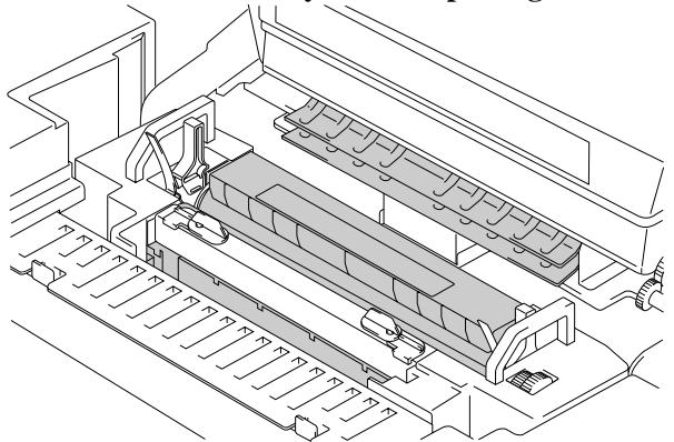
The Fusing Unit becomes extremely HOT during operation. Wait until it has cooled down sufficiently before replacing consumables.
natural_image
Technical line drawing of a mechanical assembly with no visible text or symbolsFig. 0-1 Fusing unit

Warning
If metal objects, water or other liquids get inside the printer, turn the printer off immediately and unplug the printer. Contact your dealer.

Warning
Do not put consumables such as the Toner Cartridges and the Waste Toner Pack into a fire. Some consumables can be flammable under certain conditions.

Warning
Do not look directly at the laser beam light. It might cause damage to your eyesight. Do not remove or break open the printer's safety interlocks.

Warning
Do not run the printer with the Top Cover, Front Cover and Rear Access Covers open and the interlocks removed.

Warning
Turn off the printer before replacing consumables.

Warning
Do not place any items on the printer.

Warning
In case of a fuser oil spill, you must clean it up immediately .
Printer Do's and Don'ts for Optimum Print Quality

Caution
Before you move or lift the printer, remove the Toner Cartridges, Waste Toner Pack, Oil Bottle and Fusing Unit to avoid spills. Be sure to keep the printer as level as possible. Damage caused by failure to remove the supplies will void your warranty.

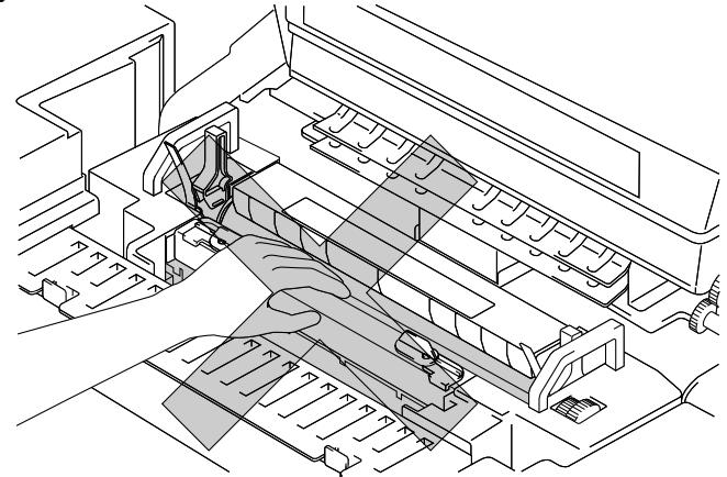
Caution
Do not touch the rollers of the Fusing Unit. This can degrade print quality.
natural_image
Technical line drawing of a mechanical assembly with no visible text or symbolsFig. 0-2 Fusing Unit Rollers
TABLE OF CONTENTS
CHAPTER 1 INTRODUCTION
ABOUT THIS MANUAL 1-1
ABOUT THIS PRINTER 1-2
Features 1-2
Options 1-6
Operating and Storage Environment 1-8
CHAPTER 2 SETTING UP THE PRINTER
BEFORE USING THE PRINTER 2-1
Checking the Components 2-1
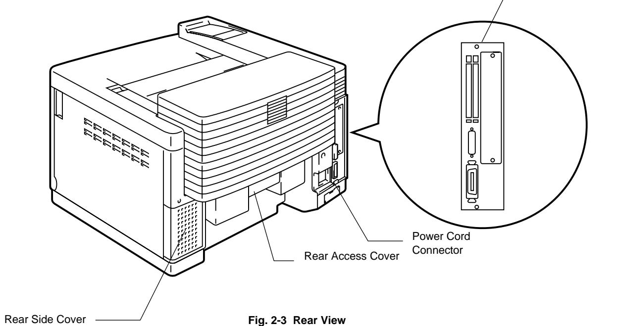
General View 2-3
SETTING UP THE PRINTER 2-4
Remove the Protective Parts 2-4
Installing the OPC Belt Cartridge 2-5
Installing the Toner Cartridges 2-7
Installing the Oil Bottle and the Fuser Cleaner 2-9
Loading Paper in the Media Cassette 2-11
Connecting the Printer to Your Computer 2-14
Turning the Printer On 2-16
Printing the Test Patterns or Lists 2-18
Install the Printer Driver 2-20
CHAPTER 3 BEFORE WORKING WITH THE PRINTER
AUTOMATIC EMULATION SELECTION 3-1
AUTOMATIC INTERFACE SELECTION 3-3
ABOUT THE CONTROL PANEL 3-5
Selecting the Local Language Display 3-5
Using the Panel Buttons 3-6
Printer Settings 3-7
PAPER HANDLING 3-8
Print Media 3-8
Cassette Feed 3-13
Manual Feed 3-14
CHAPTER 4 CONTROL PANEL
DISPLAY AND LEDS 4-1
Display 4-1
About Routine Maintenance Messages 4-4
LEDs 4-5
BUTTONS IN NORMAL MODE 4-6
SEL Button 4-6
SET Button 4-7
▲ (UP) or ▼ (DOWN) Button 4-7
MODE Button 4-8
INTERFACE MODE 4-19
FORMAT MODE 4-22
RESOLUTION MODE 4-30
PAGE PROTECTION 4-33
| REPLACING THE CONSUMABLES | 5-1 |
| Toner Cartridges | 5-3 |
| Oil Bottle | 5-6 |
| Fuser Cleaner | 5-9 |
| Waste Toner Pack | 5-11 |
| OPC Belt Cartridge | 5-13 |
| Ozone Filter | 5-16 |
| Fusing Unit | 5-17 |
| 120K Kit | 5-21 |
| CLEANING THE PRINTER | 5-28 |
| REPACKING AND RELOCATING THE PRINTER | 5-30 |
| OPTIONS | 5-31 |
| Lower Tray Unit | 5-31 |
| Loading Paper from the Lower Media Cassette | 5-31 |
| Font Card, Flash Memory/HDD Card | 5-35 |
| Selecting the Optional Fonts | 5-37 |
| Network Option | 5-38 |
| NC-3100h | 5-38 |
| Modular I/O Card | 5-41 |
| RAM Expansion | 5-42 |
| HDD (Hard Disk Drive) | 5-46 |
CHAPTER 6 TROUBLESHOOTING
TROUBLESHOOTING 6-1
Operator Call Messages 6-1
Maintenance Messages (appear on the lower row) 6-3
Error Messages 6-4
Service Call Messages 6-6
Paper Jams 6-9
Q & A 6-13
Setting Up the Printer Hardware 6-13
Setting Up the Printer 6-14
Paper Handling 6-15
Printing 6-16
Print Quality 6-17
APPENDICES
PRINTER SPECIFICATIONS A-1
Printing A-1
Functions A-2
Electrical and Mechanical A-3
PAPER SPECIFICATIONS A-4
INTERFACE SPECIFICATIONS A-8
Bi-directional Parallel Interface A-8
RS-232C Serial Interface A-11
Network Interface A-14
SYMBOL/CHARACTER SETS A-15
OCR Symbol Sets A-15
HP PCL Mode A-16
EPSON Mode A-23
IBM Mode A-26
HP-GL Mode A-28
Symbol Sets Supported by the Printer's Intellifont Compatible Typefaces A-33
Symbol Sets Supported by the Printer's TrueType™ and Type 1 Font Compatible, and
Original Typefaces A-35
Electronic Emission Notices
WITHOUT the Network Card NC-2010h, NC-2100h
Federal Communications Commission(FCC) Declaration of Conformity (For U.S.A. Only)
Responsible Party :
Brother International Corporation
100 Somerset Corporate Boulevard
Bridgewater, NJ 08807-0911, U.S.A.
declares, that the products
Product Name :
Brother Color Laser Printer HL-2400Ce
Model Numbers :
HL-C1
Product Options :
Lower Tray Unit LT24CL(LFU-1), HDD (HD-6G), NC-3100h
complies with Part 15 of the FCC Rules. Operation is subject to the following two conditions: (1) This device may not cause harmful interference, and (2) this device must accept any interference received, including interference that may cause undesired operation.
This equipment has been tested and found to comply with the limits for a Class B digital device, pursuant to Part 15 of the FCC Rules. These limits are designed to provide reasonable protection against harmful interference in a residential installation. This equipment generates, uses, and can radiate radio frequency energy and, if not installed and used in accordance with the instructions, may cause harmful interference to radio communications. However, there is no guarantee that interference will not occur in a particular installation. If this equipment does cause harmful interference to radio or television reception, which can be determined by turning the equipment off and on, the user is encouraged to try to correct the interference by one or more of the following measures:
- Reorient or relocate the receiving antenna.
- Increase the separation between the equipment and receiver.
- Connect the equipment into an outlet on a circuit different from that to which the receiver is connected.
- Consult the dealer or an experienced radio/TV technician for help.
Important
A shielded interface cable should be used in order to ensure compliance with the limits for a Class B digital device.
Changes or modifications not expressly approved by Brother Industries, Ltd. could void the user's authority to operate the equipment.
Industry Canada Compliance Statement (For Canada Only)
This Class B digital apparatus complies with Canadian ICES-003.
Declaration of Conformity (For Europe)
We, Brother Industries, Ltd.,
15-1, Naeshiro-cho, Mizuho-ku, Nagoya 467-8561, Japan
declare that this product is in conformity with the following normative documents.
Safety: EN 60950, EN 60825
EMC: EN 55022 Class B, EN 55024
following the provisions of the Low Voltage Directive 73/23/EEC and the
Electromagnetic Compatibility Directive 89/336/EEC (as amended by 91/263/EEC and 92/31/EEC).
Issued by: Brother Industries, Ltd.
Printer Products Division
Radio Interference (220-240 V Model Only)
This printer complies with EN55022(CISPR Publication 22)/Class B.
Before this product is used, ensure that you use a double-shielded interface cable with twisted-pair conductors and that is marked “IEEE 1284 compliant”. The cable must not exceed 1.8 meters in length.
WITH the Network Card NC-2010h, NC-2100h
EMC Notice
Warning
This is a Class A product. In a domestic environment this product may cause radio interference in which case the user may be required to take adequate measures.
Federal Communications Commission(FCC) Compliance Notice (For U.S.A. Only)
This equipment has been tested and found to comply with the limits for a Class A digital device, pursuant to Part 15 of the FCC Rules. These limits are designed to provide reasonable protection against harmful interference when the equipment is operated in a commercial environment. This equipment generates, uses, and can radiate radio frequency energy and, if not installed and used in accordance with the instruction manual, may cause harmful interference to radio communications.
Operation of this equipment in a residential area is likely to cause harmful interference in which case the user will be required to correct the interference at his own expense.
Important
A shielded interface cable should be used in order to ensure compliance with the limits for a Class A digital device.
Changes or modifications not expressly approved by Brother Industries, Ltd. could void the user's authority to operate the equipment.
Industry Canada Compliance Statement (For Canada Only)
This Class A digital apparatus complies with Canadian ICES-003.
Declaration of Conformity (For Europe)
We, Brother Industries, Ltd.,
15-1, Naeshiro-cho, Mizuho-ku, Nagoya 467-8561, Japan
declare that this product is in conformity with the following normative documents.
Safety: EN 60950, EN 60825
EMC: EN 55022 Class A, EN 55024
following the provisions of the Low Voltage Directive 73/23/EEC and the Electromagnetic Compatibility Directive 89/336/EEC (as amended by 91/263/EEC and 92/31/EEC).
Issued by: Brother Industries, Ltd.
Printer Products Division
Radio Interference (220-240 V Model Only)
This printer complies with EN55022(CISPR Publication 22)/Class A.
Before this product is used, ensure that you use a double-shielded interface cable with twisted-pair conductors and that is marked “IEEE 1284 compliant”. The cable must not exceed 1.8 meters in length.
International ENERGY STAR® Compliance Statement
The purpose of the International ENERGY STAR ^® Program is to promote the development and popularization of energy-efficient office equipments.
As an ENERGY STAR ^® Partner, Brother Industries, Ltd. has determined that this product meets the ENERGY STAR ^® guidelines for energy efficiency.

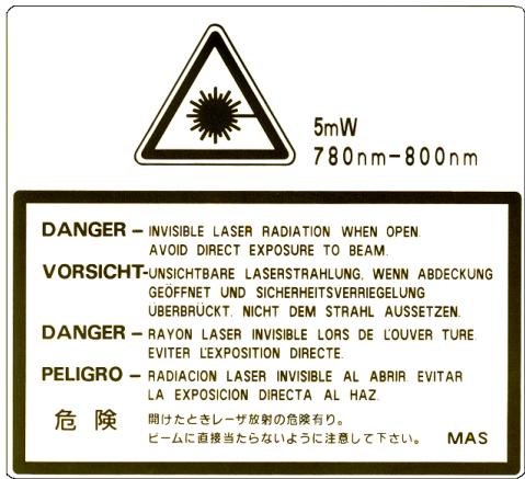
Laser Notices
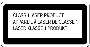
Laser Safety (For 120 V Model Only)
This printer is certified as a Class I laser product under the U.S. Department of Health and Human Services (DHHS) Radiation Performance Standard according to the Radiation Control for Health and Safety Act of 1968. This means that the printer does not produce hazardous laser radiation.
Since radiation emitted inside the printer is completely confined within protective housings and external covers, the laser beam cannot escape from the machine during any phase of user operation.
FDA Regulations (For 120 V Model Only)
U.S. Food and Drug Administration (FDA) has implemented regulations for laser products manufactured on and after August 2, 1976. Compliance is mandatory for products marketed in the United States.
Caution: Use of controls, adjustments or performance of procedures other than those specified in this manual may result in hazardous radiation exposure.
IEC 825 Specification (For 220 - 240 V Model Only)
This printer is a Class 1 laser product as defined in IEC 825 specifications. The label shown below is attached in countries where required.
This printer has a Class 3B Laser Diode that emits invisible laser radiation in the Scanner Unit. The Scanner Unit should not be opened under any circumstances.
Caution: Use of controls, adjustments or performance of procedures other than those specified in this manual may result in hazardous radiation exposure.
The following caution label is attached on the cover of the scanner unit.
For Finland and Sweden
LUOKAN 1 LASERLAITE
KLASS 1 LASER APPARAT
IMPORTANT - For Your Safety
To ensure safe operation the three-pin plug supplied must be inserted only into a standard three-pin power point that is effectively grounded through the normal household wiring.
Any extension cords used with this printer must be three-conductor and be correctly wired to provide connection to ground. Improper extension cords are a major cause of fatalities.
The fact that the equipment operates satisfactorily does not imply that the power is grounded and that the installation is completely safe. For your safety, if in any doubt about the effective grounding of the power, consult a qualified electrician.
Disconnect device
This printer must be installed near a power outlet that is easily accessible. In case of emergencies, you must disconnect the power cord from the power outlet to shut off the power completely.
Geräuschemission / Acoustic Noise Emission (For Germany Only)
Lpa < 70 dB (A) DIN 45635-19-01-KL2
Wiring Information (For U.K. only)
Important
If the mains plug supplied with this printer is not suitable for your socket outlet, remove the plug from the mains cord and fit an appropriate three pin plug. If the replacement plug is intended to take a fuse then fit the same rating fuse as the original.
If a moulded plug is severed from the mains cord then it should be destroyed because a plug with cut wires is dangerous if engaged in a live socket outlet. Do not leave it where a child might find it!
In the event of replacing the plug fuse, fit a fuse approved by ASTA to BS1362 with the same rating as the original fuse.
Always replace the fuse cover. Never use a plug with the cover omitted.
WARNING - THIS PRINTER MUST BE PROPERLY EARTHED.
The wires in the mains cord are coloured in accordance with the following code:
Green and yellow: Earth
Blue: Neutral
Brown: Live
The colours of the wires in the main lead of this printer may not correspond with the coloured markings identifying the terminals in your plug.
If you need to fit a different plug, proceed as follows.
Remove a length of the cord outer sheath, taking care not to damage the coloured insulation of the wires inside.
Cut each of the three wires to the appropriate length. If the construction of the plug permits, leave the green and yellow wire longer than the others so that, in the event that the cord is pulled out of the plug, the green and yellow wire will be the last to disconnect.
Remove a short section of the coloured insulation to expose the wires.
The wire which is coloured green and yellow must be connected to the terminal in the plug which is marked with the letter “E” or by the safety earth symbol ± or coloured green or green and yellow.
The wire that is coloured blue must be connected to the terminal which is marked with the letter “N” or coloured black or blue.
USER'S GUIDE
The wire which is coloured brown must be connected to the terminal that is marked with the letter “L” or coloured red or brown.
The outer sheath of the cord must be secured inside the plug. The coloured wires should not hang out of the plug.
CHAPTER 1 INTRODUCTION
ABOUT THIS MANUAL
This manual acts as your guide to the setup and operation of your printer and covers the following topics:
CHAPTER 1 INTRODUCTION provides an overview of the printer. Read this chapter first to get familiar with the printer.
CHAPTER 2 SETTING UP THE PRINTER gives you general set-up information about this printer. Be sure to read this chapter before you use the printer.
CHAPTER 3 BEFORE WORKING WITH THE PRINTER provides detailed information for setting up the printer to work with your computer and software. Be sure to read this chapter before you work with the printer.
CHAPTER 4 CONTROL PANEL details the functions of the panel buttons and LEDs.
CHAPTER 5 MAINTENANCE provides guidance on how to maintain your printer.
CHAPTER 6 TROUBLESHOOTING helps you troubleshoot the printer in case of problems.
APPENDICES contain printer specifications and paper specifications.
INDEX provides an alphabetical list of the contents of this manual.
Notes
When you read this User's Guide, note the following:
- This User's Guide contains instructions or steps to teach you various operations of the printer. Please remember that the instructions always assume that you start with the factory settings, particularly in Chapter 2 and Chapter 3. If you change the settings, particularly the emulation mode, the display messages change accordingly.
- The paper size has been factory set to letter or A4, depending upon the final destination of the printer. Some display messages appear differently according to this setting.
Features
This printer has the following standard features.
2400 x 600 DPI Class Resolution
This printer prints at a default resolution of 600 dots per inch (dpi). By utilizing the 300-dpi mode, the printer can also print lower resolution data, if necessary. Moreover, you can achieve higher print quality equivalent to 2400x600 DPI resolution by utilizing these Brother technologies:- High Resolution Control (HRC) and Color Advanced Photoscale Technology(CAPT).
High Speed and Color Laser Printing
You can print crisp images in brilliant 24 bit color. This printer can print at speeds up to 16 pages per minute in monochrome mode and 4 pages per minute in full color mode. The HL-2400Ce controller utilizes a high speed 64-bit RISC microprocessor and special hardware chips, to ensure fast print job processing.
Color Advanced Photoscale Technology (CAPT)
This printer can print graphics in 256 shades for each color in HP ^® color printer PCL5C ^TM emulation and BR-Script level 2, producing nearly photographic quality. CAPT is most effective when printing photographic images.
High Resolution Control (HRC)
The High Resolution Control (HRC) technology provides clear and crisp printouts and improves even 600-dpi resolution output. HRC is most effective when printing text.
Maintenance-Free and Economical Toner Cartridge
The toner cartridge can print up to 10,000 (Black) and 6,000 (Cyan, Magenta and Yellow) single-sided pages at 5% coverage. This printer uses one piece, easy-to-replace toner cartridges.
Universal Media Cassette
This printer loads paper automatically from the media cassette. Since the media cassette is a universal type, a number of different paper sizes can be used. Even envelopes can be loaded from the media cassette. For detailed paper specifications, see ‘Paper Handling’ in Chapter 3.
Three Interfaces
This printer has a high speed bi-directional parallel interface, an RS-232C serial interface and a modular input/output (MIO) compatible interface. As an alternative to the MIO interface, you can use the Brother NC-3100h Networking solution.
If your application software supports the bi-directional parallel interface, you can monitor the printer status. It is fully compatible with the industry-standard bi-directional parallel interface.
The industry standard RS-232C serial can connect to any computer using a standard serial cable.
The MIO interface allows you to install a commercial MIO-compatible card. If you install a card, you can use one more interface ports for networking or printer sharing.
The NC-3100h card will allow you to connect directly to a Network.
Automatic Interface Selection
This printer can automatically select the bi-directional parallel, RS-232C serial or MIO / NC-3100h interface depending on the interface port through which it receives data. With this feature, the printer can be connected to more than one computer.
Five Emulation Modes
This printer can emulate the Hewlett-Packard ^® Color PCL ^® 5C language (PCL6 ^® in monochrome printing) printers, PostScript ^® Level 2 language emulation (Brother BR-Script Level 2) printers, the industry-standard HP-GL ^TM plotter as well as EPSON ^® FX-850 ^TM and IBM ^® Proprinter XL ^® printers (for monochrome printing only). You can print with all application programs that support one of these printers.
Automatic Emulation Selection
This printer can automatically select the printer emulation mode depending on the print commands it receives from the computer software. With this feature, many users can share the printer on a network.
Data Compression Technology
This printer can internally compress the received graphics and font data in its memory so that it can print larger graphics and more fonts without the need for additional memory.
Fonts
This printer has 72 scalable and 12 bitmapped fonts. The fonts that can be used vary according to the selected emulation mode.
In PCL mode, you can also print the 11 kinds of bar codes listed below.
In BR-Script mode, the printer has 66 scalable fonts.
Bar Code Printing
This printer can print the following 11 types of bar codes:
- Code 39
- Interleaved 2 of 5
• EAN-8
• EAN-13 - UPC-A
• EAN-128 - UPC-E
- Codabar
- US-PostNet
• ISBN - Code 128
CCITT G3/G4
Since this printer supports the CCITT G3/G4 format in addition to HP-compatible formats, it can quickly receive and print data compressed in this format.
Lock Panel
If the panel button settings have been changed, the printer may not work as you expect. If you are an administrator of this printer, you can lock your settings to prevent changes from being made.
Power Save Mode
This printer has a power saving mode. Since laser printers consume power to keep the fixing assembly at a high temperature, this feature can save electricity when the printer is on but not being used. The factory setting of the Power Save mode is ON so that it complies with the new EPA Energy Star specification.
Toner Save Mode
This printer has an economical Toner Save Mode. By using this feature you can substantially reduce operating costs and extend the life expectancy of the toner cartridges.
Reprint Function
You can reprint the last print job with a touch of a panel button, which allows reprinting of multiple copies of the job without sending the data again from the computer.
When there is not enough memory to print the last job, you can reprint the last print page.
PCMCIA Card Slot
The printer has 2 Type II PCMCIA card slots that also allow the use of 1 Type III device. You can install PCMCIA-compatible flash memory and HDD cards.
- Flash memory card: You can store fonts, macros, logos and other print data.
- HDD card: You can store fonts, macros, logos and other print data as well as keeping data for printer usage analysis.
Saving User Settings
You can personalize the printer by customizing your own control panel button settings. Two sets of user settings can be stored.
Options
The following options are available for this printer:
Paper Handling
Lower Tray Unit
A lower tray unit expands the paper source capacity. You can load extra paper or different sizes of paper. You can load Letter, A4, B5 (JIS and ISO) or Executive size (176x250 to 215.9x297mm) paper and Com10, DL size envelopes into this cassette.
Legal Cassette
If you wish to print on Legal sized paper, you must use this cassette.
The following commercial business products can also be installed into this printer:
Network
NC-3100h
Installing an NC-3100h enables you to use the printer in the following environments:
(TCP/IP, IPX/SPX, AppleTalk, DLC/LLC, VINES, LAT, NetBEUI) Also, many useful utilities such as BR-Admin and Brother Network Printing software for the Network administrator are included. For details of the utilities, see the documentation included on the CD-ROM.
MIO Card (NC-2010h/NC-2100h)
An MIO Network Card provides a means for attaching the printer to a network. Some models of this printer include an MIO Card as standard.
PCMCIA CARDS
Flash Memory Card and HDD Card
A commercial flash memory card or an HDD card can be installed. You can store fonts, macros, logos, and other print data in a commercial PCMCIA-compatible flash memory card or HDD card.
By using the Card, you can do logging and custom web functions. You also can use the Brother Analysis Tool software and the Brother Card Monitor software. For more details on these utilities, please refer to the documentation included on the CD-ROM.
HDD (Hard Disk Drive)
By installing an optional HDD, you can save multiple print jobs onto it. You can also select your print job and re-print it through the network.
RAM
RAM Expansion
By installing commercial memory modules you can expand the memory capacity up to 288 Mbytes.

Note
Installation instructions for each of these options is contained in the manual supplied with the option.
Operating and Storage Environment
Please note the following requirements before using the printer.
Power Supply
Use the printer within the specified power range.
AC power: ±10% of the rated power voltage
Frequency: 50/60 Hz (120V or 220-240 V)
The power cord, including extensions, should not exceed 5 metres (16.5 feet).
Do not share the same power circuit with other high-power appliances, particularly an air conditioner, copier, shredder, etc. If you must use the printer with these appliances, we recommend that you use a voltage transformer or a high-frequency noise filter.
Use a voltage regulator if the power source is not stable.
Environment
Use the printer only within the following ranges of temperature and humidity.
Ambient temperature: 10^ C to 32.5^ C ( 50^ F to 90.5^ F)
Ambient humidity: 20% to 80% (without condensation)
Do not block the air exit on top of the printer. Do not place objects on top of the printer, especially on the air exit.
Ensure that the printer Ozone Filter is installed at all times.
Ventilate the room where you use the printer.
Do not place the printer where it will be exposed to direct sunlight. Use blinds to protect the printer from direct sunlight if set up near a window is unavoidable.
Do not install the printer near devices that contain magnets or generate magnetic fields.
Do not subject the printer to strong physical shocks or vibrations. Do not expose the printer to open flames or salty or corrosive gasses.
Place the printer on a flat, horizontal surface.
Keep the printer clean. Do not install the printer in a dusty place.
Do not install the printer near an air conditioner.
The following figure details the recommended area around the printer for proper ventilation, operation and maintenance.
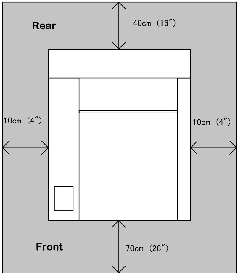
Fig. 1-1 Recommended area around the Printer
Note
Ensure that there is enough space behind the printer so that you can easily access the rear cover if a paper jam occurs.
CHAPTER 2 SETTING UP THE PRINTER
This chapter can also be used as a quick setup guide, which provides information for setting up the printer.
BEFORE USING THE PRINTER

Warning
This printer is heavy and weighs approximately 37kg (81.6 lbs). When moving or lifting this printer, be sure to do so with at least 2 people to avoid injury.
Checking the Components
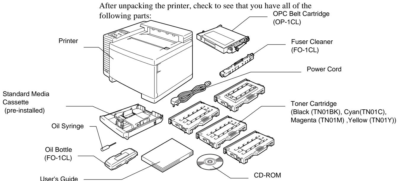
Fig. 2-1 Components in the Printer Carton

Caution
The Toner Cartridges, OPC Belt cartridge, Oil Bottle and Fuser Cleaner are packed inside a separate carton as a starter kit. Do not open them now. Only open them when you are ready to install them. The OPC Belt Cartridge must not be exposed to light for any length of time or it will be damaged.
Note
An interface cable is not a standard accessory. Please purchase the appropriate cable for the interface you intend to use. Parallel cables should be IEEE 1284 compliant and should not exceed 1.8 meters (6 feet) in length. The power cord may differ slightly from this diagram depending on the country where you purchased the printer.
Note
You may have additional parts not listed above, depending on which country you live in and the HL-2400Ce series model purchased.
Note
We recommend keeping spares of the following consumables at all times. When these are exhausted, the printer will cease printing.
* Toner Cartridges (TN-01BK, TN-01C, TN-01M, TN-01Y)
* Waste Toner Pack (WT-1CL)
* Oil Bottle and Fuser Cleaner (FO-1CL, CR-1CL)
General View
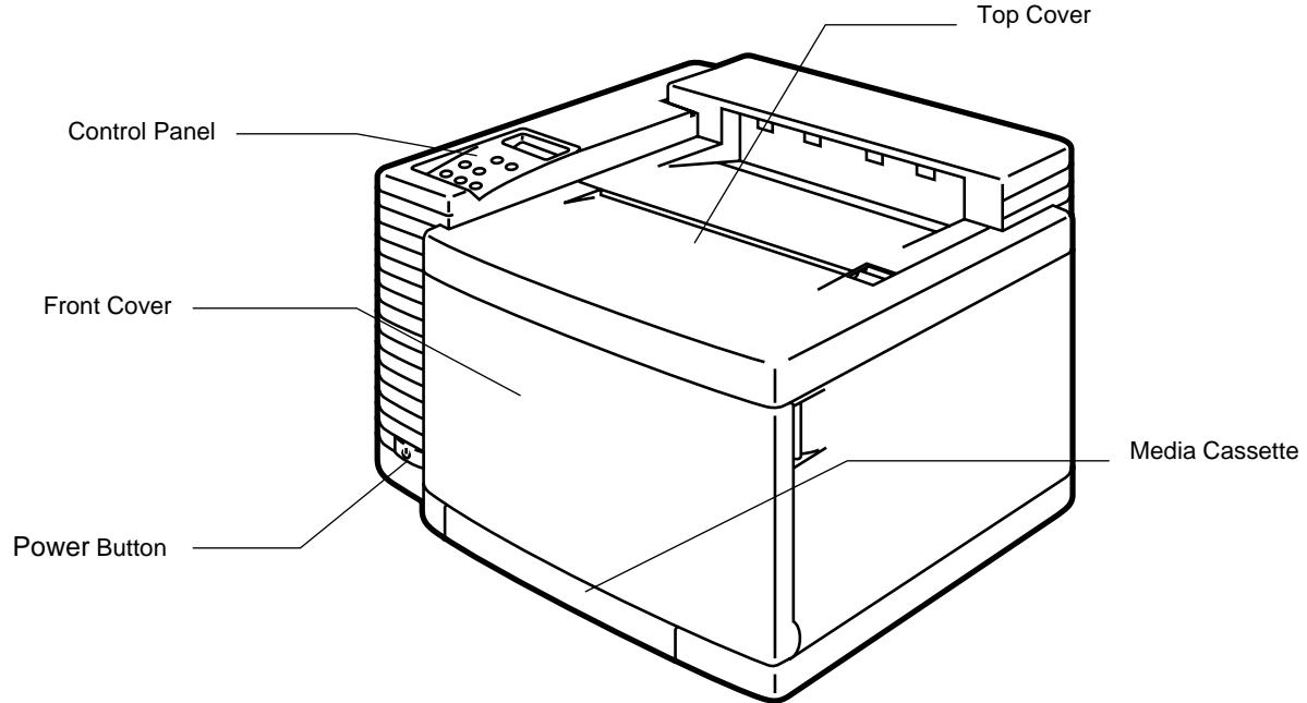
Fig. 2-2 Front View
Remove the Protective Parts
After checking that you have all of the correct parts, temporarily place the printer where you can easily reach all sides. Remove the protective parts that secure the printer against damage during transportation, as shown below:
Important Note
It is CRITICAL that you SAVE all packing materials in the event you must ship or store the printer. Failure to EMPTY, CLEAN and correctly REPACK the printer according to the manufacturer's instructions BEFORE shipment will result in serious damage to the printer. This damage may not be covered by your warranty.
- Remove the protective parts as shown below.
natural_image
Line drawing of a mechanical device with no visible text or symbols
natural_image
Technical line drawing of a mechanical device with no visible text or symbolsFig. 2-4 Removing the Protective Parts
Installing the OPC Belt Cartridge

Caution
- Do not touch the green surface of the OPC Belt Cartridge. This can degrade print quality.
-
Do not expose the OPC Belt to light (more than 800 lux) for more than approximately 2 minutes. It might cause damage to the OPC Belt Cartridge and void the warranty.
-
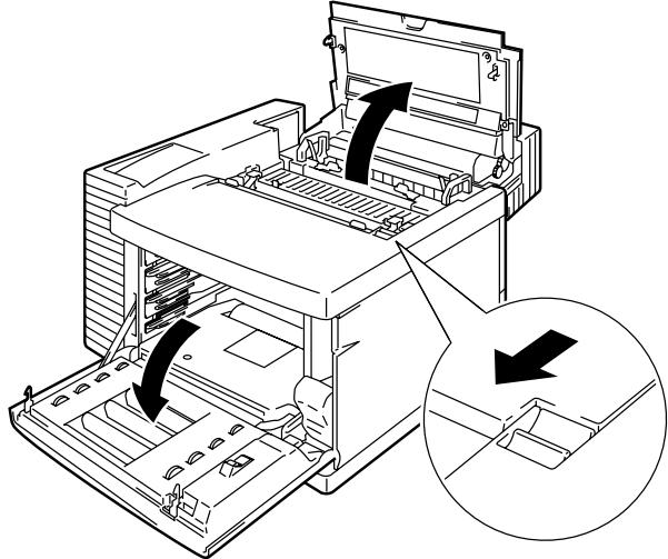
Open the Front Cover and then open the Top Cover.
natural_image
Line drawing of a printer internal structure with arrows indicating assembly or movement, no text or symbols presentFig. 2-5 Open the Covers
- Release both green Belt Cartridge Lock Levers by pulling them toward you.
natural_image
Technical line drawing of a printer internal structure with no visible text or symbolsFig. 2-6 Release the Levers
- Remove the orange OPC Belt Tension Release Pins from both sides of the OPC Belt Cartridge.

natural_image
Line drawing of a computer case with hands holding a tray and arrows indicating motion (no text or symbols)Fig. 2-7 Remove the Pins
- Remove the Protective Sheet from the OPC Belt Cartridge.
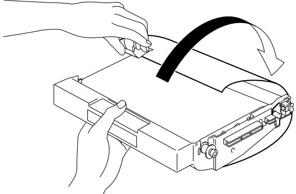
natural_image
Line drawing of hands operating a device with a curved blade and scroll (no text or symbols)Fig. 2-8 Remove the Protective Sheet
- Insert the OPC Belt Cartridge into the printer cartridge guide with the flat side facing you.
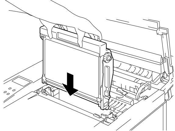
natural_image
Technical line drawing of a mechanical assembly with a downward arrow indicating a component (no text or symbols present)Fig. 2-9 Insert the (OPC) Belt Cartridge
-
Lock the Belt Cartridge Lock Levers by pushing them backward until they click into place.
-
Close the Top Cover.
Installing the Toner Cartridges
This printer uses 4 separate color (Black, Cyan, Magenta and Yellow) toner cartridges. One of each is supplied. A new cartridge contains enough toner to print up to 10,000 (Black): 6,000 (Cyan, Magenta, Yellow) A4 or letter-size single-sided pages at about 5% coverage. (Actual toner yield will depend on the images being printed.)
Note
The toner cartridges shipped with the printer are starter cartridges that contain only half the normal amount of toner. (5,000 pages (Black) and 3,000 pages (Cyan, Magenta and Yellow)).
To install the toner cartridges, follow these steps:
- Open the Front Cover of the printer.
natural_image
Technical diagram of a computer tower with highlighted internal components and directional arrows indicating movement (no text or symbols present)Fig. 2-10 Open the Front Cover
- Remove the tape labeled 'REMOVE'.
- After rocking each of the cartridges 3 to 4 times from side to side, remove the orange Protective Cover from the Toner Cartridges.
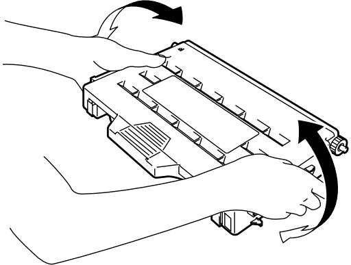
natural_image
Line drawing of a hand holding a handgun with arrows indicating motion (no text or symbols)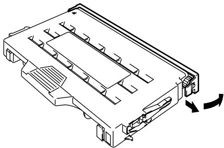
natural_image
Technical line drawing of a mechanical component with internal channels and directional arrows indicating rotation (no text or symbols)Fig. 2-11 Rocking Cartridges and Removing the Protective Cover
- Install the 4 toner cartridges by positioning them in the correct guides. Each color cartridge is individually keyed to prevent improper installation. Match each cartridge color label to the corresponding color label on the printer.
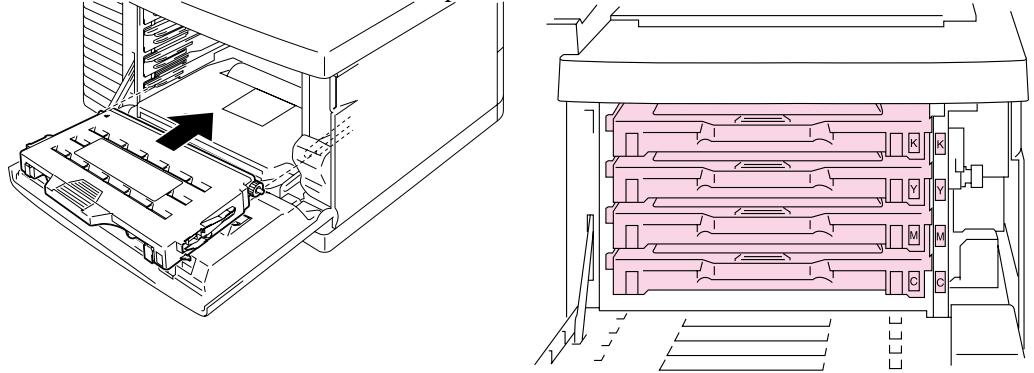
natural_image
Technical line drawing showing internal components of a printer or printer with an arrow indicating a component (no text or symbols present)Fig. 2-12 Install the Toner Cartridges
Caution
- Insert the toner cartridges gently into the printer. Do not try to lock them into the printer by pushing them all the way into the slot. The cartridges will be correctly positioned when the front cover is closed.
- Do not stand the toner cartridge on its end or turn it upside down.
- Install the toner cartridges immediately after you remove the protective cover. Do not touch the shaded part shown below.
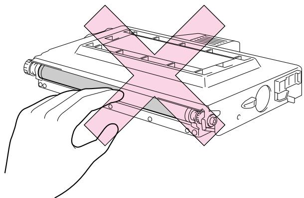
natural_image
Illustration of hands holding a device with a pink overlay, no text or symbols presentFig. 2-13 Toner Cartridge
Installing the Oil Bottle and the Fuser Cleaner
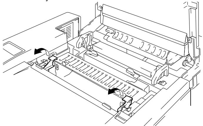
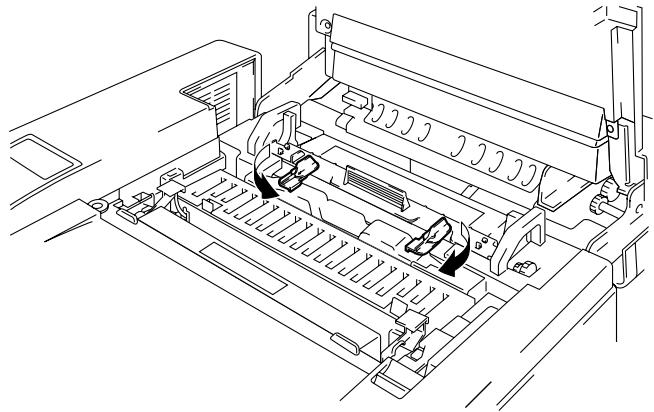
- Open the Top Cover and release the pressure on the Fusing Unit rollers by pushing the Pressure Release Levers to the OPEN position (①). Remove the orange protective parts fitted between the rollers of the Fusing Unit (②). Make sure that the Pressure Release Levers are put back to the SET position.
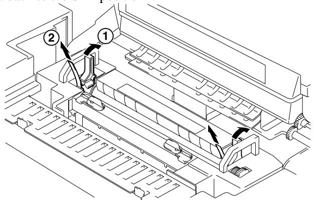
Fig. 2-14 Remove the Protective Parts
- Install the Oil Bottle into the Fusing Unit with the label side facing the front of the printer. The Oil Bottle is keyed to prevent incorrect installation.
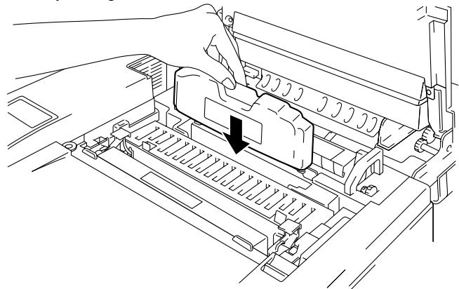
natural_image
Technical line drawing of a printer internal structure with a hand operating the top panel (no text or symbols present)Fig. 2-15 Install the Oil Bottle
Caution
Do not spill the oil inside the printer. If the oil does spill, it might cause damage to the printer. If you do spill any oil, consult your dealer or our authorized service representative.
- Place the Fuser Cleaner into the Fusing Unit with the roller side facing you.
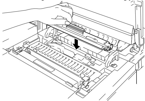
natural_image
Line drawing of a printer's internal structure showing a hand inserting a component into a tray (no text or symbols)Fig. 2-16 Install the Fuser Cleaner
- Lock the Oil Bottle and the Fuser Cleaner in place by turning the Oil Bottle Lock Levers.
natural_image
Technical line drawing of a printer internal structure with no visible text or symbolsFig. 2-17 Lock the Oil Bottle Lock Levers
- Close the Top Cover.
Loading Paper in the Media Cassette
Note
This printer has a 250 sheet Media Cassette as standard. An additional Lower Tray Unit is available as an option.
Since the Media Cassette supports universal paper types, you can place letter, A4, ISO B5 or Executive size cut sheet paper or COM10, or DL size envelopes in it.
The paper sources have the following limitations. For more information about paper, see “Paper Handling” in Chapter 3.
| Paper source | Available sizes | Capacity |
| Standard Media Cassette | cut sheet : Letter, A4, B5(ISO), B5(JIS), Executive envelope: COM 10, DLOHP film: A4, letterother sizes: width 105-216mm (4.1”-8.5”)length 220-297mm (8.7”-11.7”) | 2501550Up to approx. 250 sheets of 75g/m^2 (20 lbs.) paper |
| Optional Legal Cassette | cut sheet : Legal, Letter, A4, B5(ISO), B5(JIS), ExecutiveOHP film: A4, letterother sizes: width 105-216mm (4.1”-8.5”)length 220-355.6mm (8.7”-14”) | 25050Up to approx. 250 sheets of 75g/m^2 (20 lbs.) paper |
Note
Do not load envelopes in the Optional Legal Cassette. It may cause paper jams.
To install the Media Cassette follow these steps to set the paper guides:
Note
- Be sure to select the same paper size in your application software, or printing errors will occur.
If your application software does not support paper size selection in its print menu, you can change the paper size with the Mode button in the FORMAT MODE. For paper size change information, see “MODE Button” in Chapter 4.
- The default paper size has been factory set to letter or A4, depending upon the final destination of the printer.
- 120V model: Letter size paper set.
- 220/240V model: A4 size paper set.
- Small Size Setting: See “Control Panel” in Chapter 4
Load paper into the Media Cassette as follows:
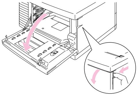
- Pull the Media Cassette out of the printer.
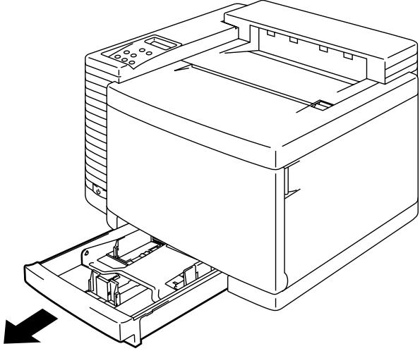
natural_image
Line drawing of a printer with an open base and internal components, showing no text or symbols.Fig. 2-18 Removing the Media Cassette
- Adjust the Paper Guides to accommodate the paper size you wish to use. Hold the shaded parts shown below and gently slide the guides into place.
Fig. 2-19 Adjust the Paper Guides
- Load paper into the Media Cassette.
Note
- Adjust the tray to the correct paper size indication arrow. If you do not adjust it correctly, the printer may detect the wrong size of paper.
- Do not load more than 250 sheets of paper (75 g/m ^2 or 20 lbs.) in the cassette, or paper jams may occur. Paper (75 g/m ^2 or 20 lbs.) should NOT be loaded above the top line on the guide.
Fig. 2-20 Paper Lines
- Install the Media Cassette into the printer.
Connecting the Printer to Your Computer
This printer has a bi-directional parallel interface and an RS-232C serial interface. They allow the printer to communicate with IBM/PC ^® or compatible computers. Before connecting the printer and computer, you need to purchase a connecting cable specifically made for the interface to be used
Since the automatic interface selection mode has been factory set, simply connect the interface cable to the printer. In some cases, you need to turn off the high-speed and bi-directional parallel communications with the Mode button. For further information, see “MODE Button” in Chapter 4.
When you use the serial interface, you need to have the same communications settings on both the printer and computer. Since the automatic interface selection mode has been factory set with certain factory settings (baud rate = 9600, code type = 8 bits, parity = none, stop bit = 1, Xon/Xoff = ON, DTR (ER) = ON, and Robust Xon = ON), you may simply connect the interface cable if these are the same as the settings on your computer. When necessary, set the communications parameters with the Mode button on the printer. For further information, see “MODE Button” in Chapter 4. For the settings on the computer, see the manual of the computer or software you use.
Connect the printer to your computer as follows:
- Make sure that both the computer and the printer are turned off.

Caution
Always turn off the printer and computer when connecting and disconnecting the cable.
Note
To use the parallel connection, only a shielded interface cable that is IEEE 1284 compliant and less than 1.8m (6 feet) long should be used.
-
Connect one end of the interface cable to the interface connector located on the back of the printer.
-
Secure the connection to the printer with the wire clips or screws.
Fig. 2-21 Connecting the Printer and Computer
- Attach the other end of the interface cable to the interface connector on your computer. Be sure to tighten the connection on the computer as well.

Note
When you connect to a network, you can use Brother NC-3100h or NC-2010h/NC-2100h Network cards. For the details, refer to the Network User's Guide.
Turning the Printer On
Installing the Power Cord and Turning the Printer On
- Make sure that the Power button is turned OFF. The power button is on the front left side of the printer.
- Attach the power cord to the printer and plug it into an AC outlet.
natural_image
Technical line drawing of a computer monitor with an attached cable outlet (no text or symbols)Fig. 2-22 Plugging in the Power Cord
- Turn the printer on by pressing the Power Button.

Caution
- Check the AC voltage. This printer should be operated at the specified voltage and frequency.
• USA and Canada: AC 120 V, 50/60 Hz
• Europe, Australia and others: AC 220 to 240 V, 50/60 Hz
- Since this printer must be electrically grounded, the power cord should be connected to a grounded AC outlet.
- The total length of the power cord, including extension cords, should not exceed 5 meters (16.4 feet). Use of a longer power cord may result in reduced voltage or malfunctions.
- Do not unplug the power cord to turn off the printer.
- The printer should be installed near a power outlet that is easily accessible.

Caution
Always wait at least 5 seconds after turning off the power before turning it on again.
Do not turn the power off while the printer is printing as this may cause a paper jam and adversely affect the printer.
The printer performs self-diagnosis at start-up to check its hardware and software. If the printer should find any problems, the display will change to show the corresponding error message. See “TROUBLESHOOTING” in Chapter 6.
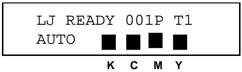
The display shows several messages quickly at start-up. If the printer detects no errors, the printer initializes. This will take several minutes during which time the LCD will display the following message :
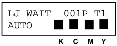
Once the printer has finished initializing, it automatically goes on-line and the message changes to show the current printer status and settings as shown below:
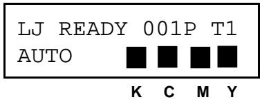
AUTO: The auto emulation selection mode is set.
LJ : The auto emulation selection is set and currently the HP PCL5C emulation is selected.
READY : The printer is ready to print.
001 : The number of copies to print is set to 1.
P : Portrait print is selected.
T1 : Paper is fed from Tray1.
■ : Toner cartridges are full. When the toner cartridges become nearly empty, the ■ indication blinks. The ■
indication disappears when a color toner is empty.
Printing the Test Patterns or Lists
You can check print quality and print a list of available fonts before you actually start working with the printer. To do so, follow these steps:
- Make sure that you have already installed the toner cartridges, the OPC Belt Cartridge, the Oil Bottle and the Fuser Cleaner and have loaded paper into the cassette. Make sure that you have removed the protective parts on the Waste Toner Pack.
- Turn on the printer. Wait until the following message is displayed:
- Press the Sel button to set the printer off-line.
The On Line LED goes off. - Hold down the Shift button and press the Test button. Release both buttons.
- Press the ▲ or ▼ button to scroll through the display until the desired message appears.
Choose from one of the following selections:
| To Print | LCD Message |
| the Demonstration Page | DEMO PAGE |
| the Test Pattern | TEST PRINT |
| the list of printer settings | PRINT CONFIG |
| the list of internal or resident fonts | PRINT FONTS I |
| the list of optional card fonts | PRINT FONTS C |
| the list of permanent download fonts | PRINT FONTS P |
To exit from the test mode, select “exit”.
Notes
The messages “PRINT FONTS C” or “PRINT FONTS P” appear only when an optional font card is installed in the font slot or when permanent download fonts are stored in printer memory.
- If the optional font card is installed, you can print a list of optional fonts. Since the list shows the ID numbers specific to each optional font, it helps you select them with the Font button. For more information, see “FONT Button” in Chapter 4.
- If user-defined characters are already downloaded into the printer memory as permanent download fonts, you can print a list of them. For more information, see “FONT Button” in Chapter 4.
6. Press the Set button.
The printer starts printing the selected test pattern or list. When the printer finishes printing, it automatically returns to the off-line mode. Press the SEL button to set the printer back on-line.
![TEST PRINT *856 *14*, - / 1234567890 : /ABCDEFHILYLKMQOSTTVVXYZ1 \* , abobefghi [kl]lenopratuowryz1 *856 *14*, - / 1234567890 : /ABCDEFHILYLKMQOSTTVVXYZ1 \* , abobefghi [kl]lenopratuowryz1 *856 *14*, - / 1234567890 : /ABCDEFHILYLKMQOSTTVVXYZ1 \* , abobefghi[kl]lenopratuowryz1 *856 *14*, - / 1234567890 : /ABCDEFHILYLKMQOSTTVVXYZ1 \* , abobefghi[kl]lenopratuowryz1 *856 *14*, - / 1234567890 : /ABCDEFHILYLKMQOSTTVVYZ1 \* , abobefghi[kl]lenopratuowryz1 *856 *14*, - / 1234567890 : /ABCDEFHILYLKMQOSTTVVYZ1 \* , abobefghi[kl]lenopratuowryz1 *856 *14*, - / 1234567890 : /ABCEFGEFLYLKMQOSTTVVXYZ1 \* , abobefghi[kl]lenopratuowryz1 *856 *14*, - / 1234567890 : /ABCDEFHILYLKMQOSTTVVXYZ1 \* , abobefghi[kl]lenopratuowryz1 *856 *14*, - / 123457890 : /ABCDEFHILYLKMQOSTTVVXYZ1 \* , abobefghi[kl]lenopratuowryz1 *856 *14*, - / 1234567890 : /ABCDEFHILYLKMQOSTTVVXYZ1 \* , abobefghi[kl]lenopratuowryz1 *856 *15, - / 1234567890 : /ABCDEFHILYLKMQOSTTVVXYZ1 \* , abobefghi[kl]lenopratuowryz1 *856 *15, - / 1234567890 : /ABCDEFHILYLKMQOSTTVVXYZ1 \* , abobefghi[kl]lenopratuowryy *856 *15, - / 1234567890 : /ABCDEFHILYLKMQOSTTVVXYZ1 \* , abobefghi[kl]lenopratuowryy *856 *15, - / 1234567890 : /ABCDEFHILYLKMQOSTTVVXYZ1 \* , abobefghi[ki]lenopratuowryy *856 *15, - / 1234567890 : /ABCDEFHILYLKMQOSTTVVXYZ1 \* , abobefghi[kl]lenopratuowryy *856 *15, - / 1234567890 : /ABCDEFHILYLKMQOSTTVVXYZ1 \*\* , abobefghi[kl]lenopratuowryy *856 *15, - / 1234567890 : /ABCDEFHILYLKMQOSTTVVXYZ1 \* , abobefghi[kl]lenopratuowryy *856 *15, - / 1234567890 : /ABCDEFHILYKLKMQOSTTVVXYZ1 \* , abobefghi[kl]lenopratuowryy *856 *15, - / 1234567890 : /ABCDEFHILYKLKMQOSTTVVXYZ1 \* , abobefghi[kl]lenopratuowryy *856 *15, - / 123456790 : /ABCDEFHILYLKMQOSTTVVXYZ1 \* , abobefghi[kl]lenopratuowryy *856 *15, - / 123456790 : /ABCDEFHILYLKMQOSTTVVXYZ1 \* , abobefghi[kl]lenopratuowryy *856 *15, - / 123456790: ABCEFGEFLYLKMQOSTTVVXYZ1 \* , abobefghi[kl]lenopratuowryy *856 *15, - / 123456790: ABCEFGEFLYLKMQOSTTVVXYZ1 \* , abobefghi[kl]lenopratuowryy *856 *15, - / 123456792: ABCEFGEFLYLKMQOSTTVVXYZ1 \* , abobefghi[kl]lenopratuowryy *856 *15, - / 123456792: ABCEFGEFLYLKMQOSTTVVXYZ1 \* , abobefghi[kl]lenopratuowryy *856 *15, - / 1223456790: ABCEFGEFLYLKMQOSTTVVXYZ1 \* , abobefghi[kl]lenopratuowryy *856 *15, - / 123456790: ABCEFGEFLYLKMQOSTTVVXYZ1 \* , abobefghi[kl]lenopratuowryy *856 *2, - / 123456790: ABCEFGEFLYLKMQOSTTVVXYZ1 \* , abobefghi[kl]lenopratuowryy *856 *2, - / 123456790: ABCEFGEFLYLKMQOSTTVVXYZ1 \* , abobefghi[kl]lenopratuowryy *2, - / 123456790: ABCEFGEFLYLKMQOSTTVVXYZ1 \* , abobefghi[kl]lenopratuowryy *2, - / 123456790: ABCEFGEFLYLKMQOSTTVVXYZ1 \* , abobefghi[kl]lenopratuowryy *2, -/2, - / 123456790: ABCEFGEFLYLKMQOSTTVVXYZ1 \* , abobefghi[kl]lenopratuowryy *2, -/2, - / 123456790: ABCEFGEFLYLKMQOSTTVVXYZ1 \* , abobefghi[kl]lenopratuowryy - / 1, - / 123456790: ABCEFGEFLYLKMQOSTTVVXYZ1 \* , abobefghi[kl]lenopratuowryy - / 1, - / 123456790: ABCEFGEFLYLKMQOSTTVVXYZ1 \* , abobefghi[kl]lenopratuowryy - / 2, - / 123456790: ABCEFGEFLYLKMQOSTTVVXYZ1 \* , abobefghi[kl]lenopratuowryy - / 2, - / 123456790: ABCEFGEFLYLKMQOSTTVVXYZ1 \* , abobefghi[kl]lenopratuowryy - / 3, - / 123456790: ABCEFGEFLYLKMQOSTTVVXYZ1 \* , abobefghi[kl]lenopratuowryy - / 3, - / 123456790: ABCEFGEFLYLKMQOSTTVVXYZ1 \* , abobefghi[kl]lenopratuowryy - / 4, - / 123456790: ABCEFGEFLYLKMQOSTTVVXYZ1 \* , abobefghi[kl]lenopratuowryy - / 4, - / 123456790: ABCEFGEFLYLKMQOSTTVVXYZ1 \* , abobefghi[kl]lenopratuowryy - / 5, - / 123456790: ABCEFGEFLYLKMQOSTTVVXYZ1 \* , abobefghi[kl]lenopratuowryy - / 5, - / 123456790: ABCEFGEFLYLKMQOSTTVVXYZ1 \* , abobefghi[kl]lenopratuowryy - / 6, - / 123456790: ABCEFGEFLYLKMQOSTTVVXYZ1 \* , abobefghi[kl]lenopratuowryy - / 7, - / 123456790: ABCEFGEFLYLKMQOSTTVVXYZ1 \* , abobefghi[kl]lenopratuowryy - / 8, - / 123456790: ABCEFGEFLYLKMQOSTTVVXYZ1 \* , abobefghi[kl]lenopratuowryy - / 9, - / 123456790: ABCEFGEFLYLKMQOSTTVVXYZ1 \* , abobefghi[kl]lenopratuowryy - / 10, - / 123456790: ABCEFGEFLYLKMQOSTTVVXYZ1 \* , abobefghi[kl]lenopratuowryy - / 11, - / 123456790: ABCEFGEFLYLKMQOSTTVVXYZ1 \* , abobefghi[kl]lenopratuowryy - / 12, - / 123456790: ABCEFGEFLYLKMQOSTTVVXYZ1 \* , abobefghi[kl]lenopratuowryy - / 13, - / 123456790: ABCEFGEFLYLKMQOSTTVVXYZ1 \* , abobefghi[kl]lenopratuowryy - / 14, - / 123456790: ABCEFGEFLYLKMQOSTTVVXYZ1 \* , abobefghi[kl]lenopratuowryy - / 15, - / 123456790: ABCEFGEFLYLKMQOSTTVVXYZ1 \* , abobefghi[kl]lenopratuowryy - / 2, - / 123456790: ABCEFGEFLYLKMQOSTTVVXYZ1 \* , abobefghi[kl]lenopratuowryy - / 4, - / 123456790: ABCEFGEFLYLKMQOSTTVVXYZ1 \* , abobefghi[kl]lenopratuowryy - / 7, - / 123456790: ABCEFGEFLYLKMQOSTTVVXYZ1 \* , abobefghi[kl]lenopratuowryy - / 9, - / 123456790: ABCEFGEFLYLKMQOSTTVVXYZ1 \* , abobefghi[kl]lenopratuowryy - / 2, - / 123456790: ABCEFGEFLYLKMQOSTTVVXYZ1 \* , abobefghi[kl]lenopratuowryy - / 7, - / 123456790: ABCEFGEFLYLKMQOSTTVVXYZ1 \* , abobefghi[kl]lenopratuowryy - / 2, - / 123456790: ABCEFGEFLYLKMQOSTTVVXYZ1 \* , abobefghi[kl]lenopratuowryy - / 8, - / 123456790: ABCEFGEFLYLKMQOSTTVVXYZ1 \* , abobefghi[kl]lenopratuowryy - / 2, - / 123456790: ABCEFGEFLYLKMQOSTTVVXYZ](/content/2025/01/74858/images/dfc43214e95e61271e14d233b17c37b2c4f17ddf2f0d570c944ce15f52fcb806.jpg)
TEST PRINT
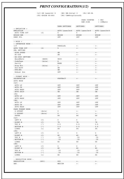
PRINT CONFIG
PRINT FONTS I
Fig. 2-23 Test Pattern, Setting List and Font List
*The test pattern, setting list and font list are subject to change without notice.
Install the Printer Driver
Computer Requirements
The following are the minimum computer requirements to setup and operate the printer:
| CPU: | 80486 or higher(Pentium recommended) |
| RAM: | 8 MB or more for Windows ^ 95/ 98, 3.1x and Windows NT ^ 4.0(16 MB or more recommended) |
| Hard Disk Drive: | 10Mbyte free space available for the driver and Fonts (more space is necessary for printing) |
| OS: | Windows ^ 95/ 98, 3.1x and Windows NT ^ 4.0 |
For Windows ^® 3.1x, 95/98 & Windows NT ^® 4.0 Users
You can set up the printer easily by following the Initial Setup instructions on the supplied CD-ROM.
- Turn your PC power on and insert the CD-ROM into the CD-ROM drive.
- The opening screen will appear automatically in Windows ^® 95/98/WindowsNT ^® 4.0.
- If the screen does not appear, click 'Start' and choose 'Run', enter the CD drive letter and type 'START.EXE'.
If you are using Windows ^® 3.1x, click 'Run' from the 'File Menu' in 'Program Manager', enter the CD drive letter and type 'START.EXE'. - Select 'HL-2400Ce series', and then select the language you require and follow the on screen instructions.
- Click the 'Install Driver & Software', select the printer driver type you want to install and you can install the driver and fonts immediately.
- After the printer driver has been installed, the HL-2400Ce series window will appear. Follow the onscreen messages to complete the installation.
Notes
- The installer automatically updates your SYSTEM.INI Windows ^® file by adding DEVICE=bi-di.386 under the [386Enh] section. If any bi-directional parallel communications device driver was installed previously, it will be deactivated by the new driver. If you wish to use old driver, you should re-install it. Re-installing the previous driver will make the new HL-2400Ce driver inactive.
- The installer makes the installed printer driver the Windows® default.
- The installer automatically sets the printer port to the parallel interface, LPT1.
- During this installation, changes have been made to the SYSTEM.INI file. It is necessary to restart Windows ^® so that the changes become effective and the installed bi-directional parallel communications device driver can take effect.
For Macintosh Users
Note
- The installer for the Macintosh driver works on OS System version 7.5.3 or higher.
-
The PPD file can be used in Laser Writer Driver version 8.4.3 or higher.
-
Insert the CD-ROM into your CD-ROM drive.
- Double click the 'BR-Script PPD Installer' icon.
- Follow the instructions that appear on the screen.
Notes
For installation of other printer drivers and information on the latest printer drivers see: http://www.brother.com
CHAPTER 3 BEFORE WORKING WITH THE PRINTER
AUTOMATIC EMULATION SELECTION
This printer has an automatic emulation selection function. When the printer receives data from the computer, it automatically selects the emulation mode. This function has been factory set to ON.
The printer can select the emulation among the following combinations:
| EPSON/IBM Priority | EPSON (default) | IBM |
| Auto Selection Mode | HP PCL 5C | HP PCL 5C |
| BR-Script 2 | BR-Script 2 | |
| HP-GL | HP-GL | |
| EPSON FX-850 | IBM Proprinter XL |
To get the most out of this laser printer, we recommend you use the Brother BR-Script 2 emulation.
The printer is set to the HP color printer emulation (PCL5C) mode automatically. Since PCL5C mode takes the highest priority in the automatic emulation selection, you can start using the printer as it is with the factory settings in most cases.
When the automatic emulation selection is active, you can check the current emulation on the display. When the printer is in ready, print or wait modes, the display reads as follows:
| Emulation | Status Display in Ready State | |||
| HP PCL5C | LJ | READY | 001P | T1 |
| BR-Script 2 | BS | IDLE | 001P | T1 |
| HP-GL | GL | READY | 001P | T1 |
| EPSON FX-850 | FX | READY | 001P | T1 |
| IBM Proprinter XL | PR | READY | 001P | T1 |
Notes
Emulation modes other than PCL5C and BR-Script 2 are monochrome emulation modes.
To select the emulation mode manually, use the Emulation button. For further information, see “EMULATION Button” in Chapter 4.
Notes
When you use the automatic emulation selection, note the following:
- Once the emulation is automatically changed, it is not changed again for a short period of time. This time period is called “Time Out” and it can be set with the Emulation button. The factory setting is 5 seconds.
- The EPSON or IBM emulation mode priority must be selected, since the printer cannot distinguish between them. The factory default setting is EPSON emulation mode. If you wish to use IBM emulation, you will need to select it manually using the Emulation button Try this function with your application software or network server. If the function does not work properly, select the required emulation mode manually using the printer panel buttons or use emulation selection commands from your software.
AUTOMATIC INTERFACE SELECTION
This printer has an automatic interface selection function. When the printer receives data from the computer, it automatically selects the bidirectional parallel, RS-232C serial interface, NC-3100h or MIO interface as appropriate.
When you use the parallel interface, you can turn the high-speed and bidirectional parallel communications on or off with the Mode button. For more information, see “MODE Button” in Chapter 4. Since the automatic interface selection mode has been factory set to ON, simply connect the interface cable to the printer. (Note: Always turn off both your computer and printer when connecting or disconnecting the cable).
When using the serial interface, you must have the same communication settings on both the printer and computer. Since the automatic interface selection mode has been factory set for standard computer serial link, you may be able to simply connect the interface cable to the printer if your computer already has the settings detailed below:
| Communications Parameters | Factory Settings |
| Baud rate (data transfer speed) | 9600 |
| Code type (data length) | 8 bits |
| Parity (data error check) | None |
| Stop bit (data separator) | 1 stop bit |
| Xon/Xoff (handshake protocol) | ON |
| DTR (ER) | ON |
| Robust Xon | OFF |
If a commercial interface card has been installed in the MIO card slot, it can be selected automatically.
When necessary, select the interface or the serial communications parameters manually with the Mode button (INTERFACE MODE) on the printer. For more information, see “MODE Button” in Chapter 4. For the settings on your the computer, please refer to your user’s manual for your computer or application software.
Notes
When you use the automatic interface selection, note the following:
- Once the interface is automatically changed, it is not changed again for a short period of time. This time period is called “Time Out” and it can be set with the Mode button. The factory setting is 5 seconds.
- The communications parameters [ baud rate, code type, parity, stop bit, Xon/Xoff, DTR(ER), and Robust Xon] must be set for the serial interface. Although they have been factory set as shown in the above table, you may need to change them with the Mode button.
- The automatic interface selection function takes a few seconds to work. If you want to speed up printing, select the required interface manually via the Mode button.
If you typically use only one interface, we recommend you select that interface as your default.. If only one interface is selected, the printer will allocate all of the input buffer to that interface.
ABOUT THE CONTROL PANEL
Selecting the Local Language Display
The display shows the current printer status. When you operate the control panel buttons, it shows functions and settings. If a problem occurs, it shows the corresponding error message. These messages are displayed in several languages. The default is English.
- English
- German
- Spanish
- French
- Dutch
- Italian
To change to another language:
- Turn off the printer.
- Hold down the Form Feed button and turn on the printer.
The message “SELF TEST” appears. Continue holding down the Form Feed button until the message changes to “LANG.=ENGLISH *”. Release the Form Feed Button - Press the ▲ or ▼ button until your desired language appears on the display.
- Press the Set button to make the selected language messages effective.
An asterisk (*) appears at the end of the display for a short time, and then the printer automatically returns to the on-line state with the selected language on the display.
Using the Panel Buttons
The printer has a versatile control panel. It has two operation modes:
When you press the buttons, they work in the NORMAL mode indicated by the function shown above the buttons. When you press the buttons with the Shift button held down, they work in the SHIFT mode as indicated by the function shown below the buttons. You can control the basic printer operations and make various printer settings in the NORMAL and SHIFT modes.
For more information, see “BUTTONS IN NORMAL MODE” and “BUTTONS IN SHIFT MODE” in Chapter 4.
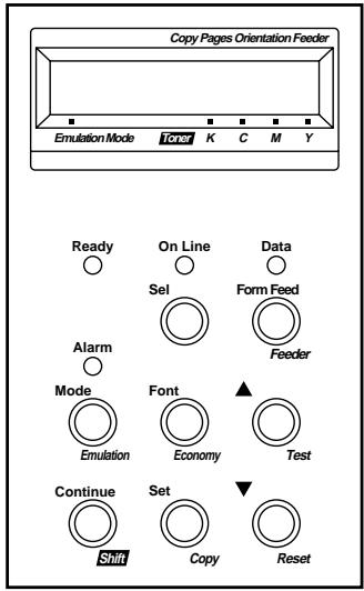
Display – Shows various messages.
READY – Lights when the printer is ready to print. ON LINE – Lights when the printer is in the on- line state.
DATA – Blinks when data is being received and lights when unprinted data remains in printer memory.
SEL – Selects on-line or off-line mode.
FORM FEED – Prints remaining data or reprints the same print job or page.
FEEDER – Selects paper source and media type to be used.
ALARM – Lights if any errors occur.
MODE – Sets functions in various modes. FONT – Selects font and character set.
▲ (UP) – Scrolls forward through modes and settings.
EMULATION – Selects printer emulation. ECONOMY – Selects toner save or power save mode.
TEST – Prints self-test pattern or fonts.
CONTINUE – Ignores the error and resumes operation.
SET – Sets selected mode and functions.
▼ (DOWN) – Reverse scroll through modes and settings.
SHIFT – Shifts button operation.
COPY – Sets the number of copies to print.
RESET – Resets printer or restores to factory settings.
Fig. 3-1 Button Operation in NORMAL and SHIFT Modes
Note
When the printer is used in the BR-Script 2 mode, some buttons are not used.
Printer Settings
There are two types of printer settings available on this printer:
- User Settings
- Factor y Settings
You can operate the printer with the factory default settings with the control panel settings unchanged. You may change and store personalized settings in the printer memory as user settings.
Remember, User Settings will replace the Factory Default Settings. The new User Settings will remain effective until new settings are made, or the Factory Default Settings are restored.
User Settings
Although the printer settings have been set at the factory, you can change them with the control panel buttons. Your changes will be stored in the printer's memory as “User Settings.” They are recalled every time you turn on the printer.
In addition to the current settings, you can save two more sets of User Settings with the eMode button and restore them with the Reset button. The current settings are cleared after restoring one of the saved user settings.
Factory Settings
The printer settings have been set at the factory before shipment. They are called “Factory Settings.” Although you can operate the printer with these factory settings unchanged, you can tailor the printer by making User Settings.
Note
Changing the User Settings does not affect Factory Settings. You cannot modify the preset Factory Default Settings.
Factory default settings can be restored via the Reset button. For more information, see “RESET Button” in Chapter 4.
Print Media
Paper Size
1. The Standard Media C assette
Since the Media C assette is a universal type, you can use any of the paper sizes listed below.. The cassette can hold up to 250 sheets of paper (75 g/m ^2 or 20 lbs.) or up to 15 envelopes (paper should be loaded only up to the top line on the sliding guide).
- Plain paper from 105 mm x 220 mm (4.1" x 8.7") to 216 mm x 297 mm (8.5" x 11.7") [Weight = 60 to 160 g/m ^2 (16 to 43 lbs)]
• Overhead projector (OHP) films (up to 50 sheets can be loaded)
• Envelopes of COM10, DL size
2. The Optional Legal Cassette
The cassette can hold up to 250 sheets of paper (75 g ^2 mr 20 lbs.). If you want to print on legal size paper, you must use this cassette.
- Plain paper from 105 mm x 220 mm (4.1" x 8.7") to 216 mm x 355.6 mm (8.5" x 14") [Weight = 60 to 160 g/m ^2 (16 to 43 lbs)]
• Overhead projector (OHP) films (up to 50 sheets can be loaded)
• Envelopes of COM10, DL size
The following are the specifications of paper suitable for this printer.
| Item | Recommended paper specification | Xerox 4024 | Hammermill Laserprint |
| Basis Weight (g/m2) | 82±5 | 75±4 | 90±4 |
| Thickness (μm) | 95±6 | 102±6 | 105±6 |
| Smoothness (Bekk) | 90±20 | 35±4 | 120±20 |
| Stiffness (Clark) | 100±15 | 100±15 | 90±15 |
| Surface Resistance X109(○) | 1010-1011 | 10-100 | 10-100 |
| CIE LAB L* | —— | 94±2 | 94±2 |
| CIE LAB a* | —— | 0.4±1 | -0.5±1 |
| CIE LAB b* | —— | 1.6±1 | 2.2±1 |
| Brightness (%) | 85±2 | 80±2 | 85±2 |
| Grain Direction | Long | Long | Long |
* Back of paper
| paper source | available size and paper type | capacity |
| Standard Media Cassette | cut sheet : Letter, A4, B5(ISO), B5(JIS), Executive envelope: COM 10, DLOHP film: A4, letterother sizes: width 105-216mm (4.1”-8.5”)length 220-297mm (8.7”-11.7”) | 2501550Up to 250 sheets of 75g/m^2 (20 lbs.) paper |
| Optional Legal Cassette | cut sheet : Legal, Letter, A4, B5(ISO),B5(JIS), ExecutiveOHP film: A4, letterother sizes: width 105-216mm (4.1”-8.5”)length 220-355.6mm (8.7”-14”) | 25050Up to 250 sheets of 75g/m^2 (20 lbs.) paper |
Recommended Paper
The recommended paper type for this printer is:
Xerox 4024, Hammermill Laserprint or equivalent
Note
- To get the best output quality and to avoid any damage, use smooth white paper.
- We recommend that you test paper, especially special sizes and types of paper, on this printer before purchasing large quantities.
- Print quality will vary depending on the paper being used.
Note
Do not load envelopes in the Paper cassette in the Optional Lower Tray Unit. It may cause paper jams.
Printable Area
The Printable Area depends on the settings in your application. The figure below shows the physically printable area and non guaranteed print area of various paper types with this printer.
Cut Sheet
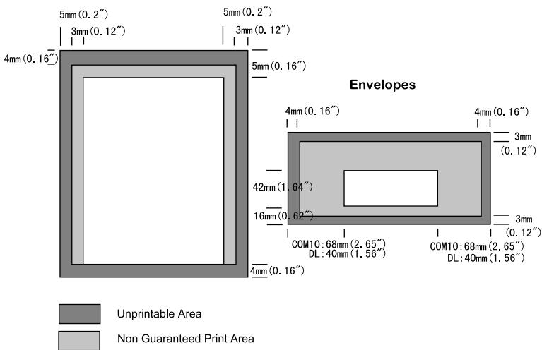
Fig. 3-2 Printable Area and Non Guaranteed Print Area

Note
If you use paper that does not meet the specifications listed in this User's Guide the life of the various consumables and parts may be reduced.
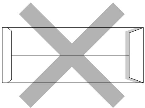
Using Envelopes
Avoid using envelopes with the following characteristics:
- Glossy or shiny surfaces
- Protection cover on the envelopes' adhesive parts
• Sealing flaps that have not been folded at purchase
• Sealing flaps as shown below
natural_image
Pure geometric diagram with intersecting X and Y axes, no text or symbols present• Three or more layers of paper in the marked area
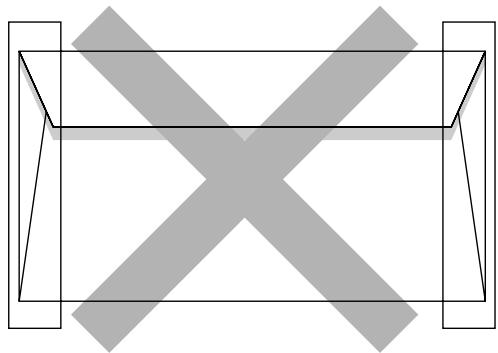
natural_image
Pure geometric diagram with intersecting lines and shaded regions, no text or symbols present• Each side folded as shown below
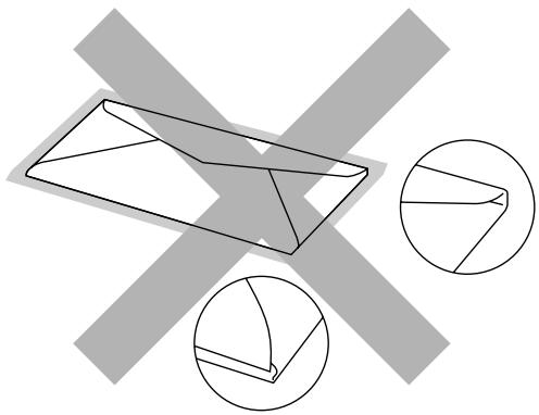
natural_image
Geometric diagram showing a 3D polyhedron intersected by two gray X-shaped planes, with two circular insets highlighting different geometric shapes (no text or symbols)Fig. 3-3 Envelope Information
Before loading envelopes in the cassette, check the following:
• Envelopes should have a lengthwise sealing flap.
- The sealing flaps should be crisply and correctly folded (irregularly cut or folded envelopes may cause paper jams).
- Envelopes should consist of two layers of paper in the following marked area.
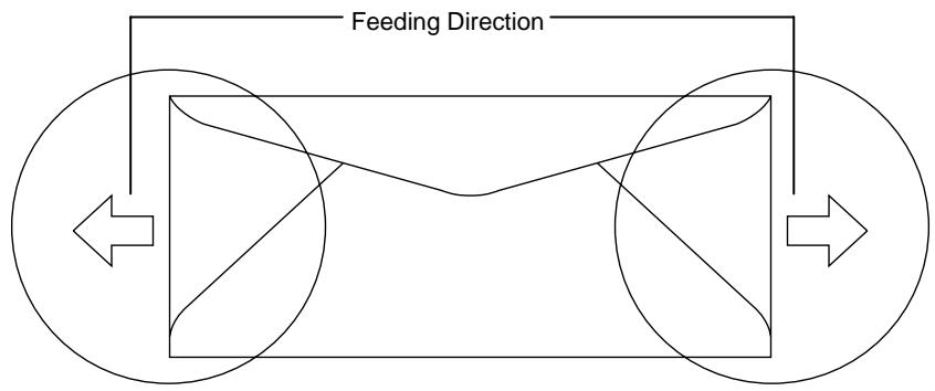
flowchart
graph TD
    A["Feeding Direction"] --> B["Central Box"]
    B --> C["Left Arrow"]
    B --> D["Right Arrow"]
Fig. 3-4 Envelopes
- Envelope joints that are sealed by the manufacturer should be secure.
- All sides should be properly folded without any wrinkles or creases.
- Print quality may vary between different style envelopes. It is a good idea to test the envelopes you wish to use prior to purchasing large quantities.
Cassette Feed
The printer can feed paper from the Media Cassette, Optional Lower Media Cassette or Optional Legal Cassette.
Notes
When you load paper into the Media Cassette, note the following:
- If your application software supports paper size selection on the print menu, you can select it through the software. If your application software does not support it, you can set the paper size with the printer driver or with the Mode button on the control panel.
- The paper size has been factory set to letter for 120V models or A4 for 220/240V models. If you want to use other sizes of paper or envelopes, change the paper size in the PAGE FORMAT MODE of the FORMAT MODE with the Mode button. For paper size selection, see “MODE Button” in Chapter 4.
- If you use pre-printed paper in the cassettes, please note that the paper should be loaded with the printed side face up and the top edge of the paper at the back of the cassette.
You can set the paper size for the Media Cassette with the Mode button in the PAGE FORMAT mode. The printer automatically detects the paper size you set in the Media Cassette. If you load a different size of paper in the Media Cassette from the size selected with the Mode button or through your application software, the printer prompts you to load the correct size of paper as follows:
T1 LOAD PAPER
**** SIZE
( * * * * indicates the paper size you have selected with the Mode button in the PAGE FORMAT mode or through your application software.)
Manual Feed
Since this printer does not have a manual feed or multi purpose tray, you cannot manually feed irregular sized paper.. However, this printer has a special Manual Feed Mode using Tray 1 (upper tray) to accommodate non-standard paper sizes.
See “Manual Mode” in Chapter 4 for more information on selecting this setting in the printer control panel.
- When the manual feed command is selected, the printer waits until you load the paper in Tray 1 during manual feed mode operation.
T1 MANUAL FEED
**** SIZE
- Pull out Tray 1 and place the paper you are going to use in the tray. It may be necessary to remove some or all of the paper stack first, depending on the size of paper in the tray and the size of the paper you wish to print on manually.
- Re-install Tray 1 and press the Continue button. The printer then starts printing.
Note
- Print quality may be affected by the type of paper you use and the print image.
- You may experience poor paper feeding during Duplex printing.
- This machine is not designed for continuous Duplex printing.
- When you do manual duplex printing, if you leave the printer for more than 5 minutes after you have finished printing the first side, the printer will reset the function automatically.
CHAPTER 4 CONTROL PANEL
DISPLAY AND LEDS
This printer has one liquid crystal display (LCD) and four LEDs on the control panel. The display can show various messages with up to 16 characters in two rows. The LEDs light to indicate the current printer status.
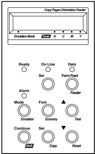
Fig. 4-1 Display and LEDs
Display
The display usually shows the current printer status and emulation mode setting and toner status. When you operate the control panel, you can change settings interactively on the display.
When you take the printer off-line, the display changes to show the currently emulation and informs you that you can change settings in the current emulation.
If any problems occur, the display shows the corresponding operator call, error, or service call message to prompt you to take an action. For more information on these messages, see “TROUBLESHOOTING” in Chapter 6.
Printer Status Messages (on the upper row)
The following table shows the printer status messages that are displayed during normal operation:
| Printer Status Message | Meaning |
| 00 READY 001P T1 | The printer is ready to print. |
| 00 IDLE 001P T1 | The printer is idle. (BR-Script 2 mode only) |
| AUTO PCL5C | The printer is off-line and currently in HP PCL5C mode under AUTO emulation mode selection. |
| HP PCL5C | The printer is off-line and in HP PCL5C mode under HP LaserJet emulation mode manual selection. |
| 00 BUSY 001P T1 | The printer is busy. (BR-Script 2 mode only) |
| 00 SLEEP 001P T1 | The printer is in sleep status (power save mode). |
| 01 PRINT 001P T1 | The printer is printing. |
| 01 PR300 001P T1 | The printer is printing by decreasing the resolution from 600 dpi to 300 dpi because of insufficient memory. |
| 02 WAIT 001P T1 | The printer is warming up. |
| 04 SELF TEST | The printer is performing self-diagnosis. |
| 05 TEST PRINT | The printer is printing the test pattern. |
| 06 DEMO PAGE | The printer is printing the demonstration. |
| 06 PRINT CONFIG | The printer is printing the list of the current printer settings. |
| 06 PRINT FONTS I | The printer is printing the list of the internal or resident fonts. |
| 06 PRINT FONTS C | The printer is printing the list of the optional fonts stored in an installed font card. |
| 06 PRINT FONTS P | The printer is printing the list of the permanent download fonts. |
| 06 DEVICE1 PRINT | The printer is printing the contents of a flash memory card in slot 1. |
| 06 DEVICE2 PRINT | The printer is printing the contents of a flash memory card or HDD card in slot 2. |
| 06 DEVICE3 PRINT | The printer is printing the contents of optional HDD. |
| Printer Status Message | Meaning(Continued) |
| 07 FF PAUSE | The printer has suspended feeding forms. Pressing the Sel button resumes form feed. |
| 08 RESET TO USER SETTINGS | The printer is restoring itself to the user settings you selected with the panel buttons. (The message appears only momentarily.) |
| 08 RESET TO SETTING 1 | The printer is restoring itself to the user 1 settings. (The message appears only momentarily.) |
| 08 RESET TO SETTING 2 | The printer is restoring itself to the user 2 settings. (The message appears only momentarily.) |
| 09 RESET TO FACTORY SETTINGS | The printer is restoring itself to the factory settings. (The message appears only momentarily.) |
| Now initializing | The printer is initializing the MIO card or initializing the printer for BR-Script 2 emulation. |
| 09 RESET FC ROLLER LIFE | The printer has reset the Fuser Cleaner life counter. Refer to Chapter 5 for details. |
| 09 RESET OPC BELT LIFE | The printer has reset the (OPC) Belt Cartridge life counter. Refer to Chapter 5 for details. |
| 09 RESET FUSER UNIT LIFE | The printer has reset the Fusing Unit life counter. Refer to Chapter 5 for details. |
| 09 RESET 120K KIT LIFE | The printer has reset the 120K Kit life counter. Refer to Chapter 5 for details. |
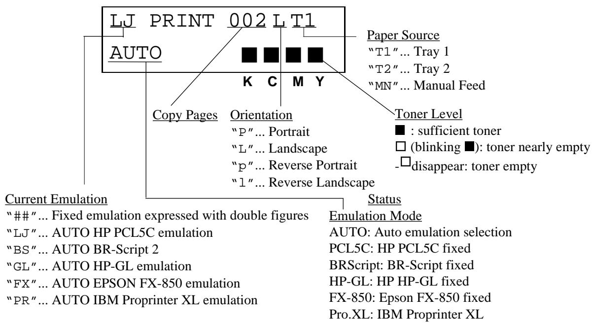
flowchart
graph TD
    A["LJ PRINT 002 LT1"] --> B["AUTO"]
    B --> C["Copy Pages"]
    C --> D["Orientation"]
    D --> E["P"... Portrait"]
    D --> F["L"... Landscape"]
    D --> G["P"... Reverse Portrait"]
    D --> H[""1"... Reverse Landscape"]
    I["Toner Level"] --> J["■: sufficient toner"]
    I --> K["□ (blinking ■): toner nearly empty"]
    I --> L["-□ disappear: toner empty"]
    M["Current Emulation"] --> N[""###" ... Fixed emulation expressed with double figures"]
    N --> O[""LJ" ... AUTO HP PCL5C emulation"]
    N --> P[""BS" ... AUTO BR-Script 2"]
    N --> Q[""GL" ... AUTO HP-GL emulation"]
    N --> R[""FX" ... AUTO EPSON FX-850 emulation"]
    N --> S[""PR" ... AUTO IBM Proprinter XL emulation"]
    T["Status"] --> U["Emulation Mode"]
    U --> V["AUTO: Auto emulation selection"]
    U --> W["PCL5C: HP PCL5C fixed"]
    U --> X["BRScript: BR-Script fixed"]
    U --> Y["HP-GL: HP HP-GL fixed"]
    U --> Z["FX-850: Epson FX-850 fixed"]
    U --> AA["Pro.XL: IBM Proprinter XL"]
Fig. 4-2 Display
About Routine Maintenance Messages
This printer has some user serviceable parts that require periodic replacement. The printer counts the number of printed pages and detects the life of each of these parts. When the part nears the end of its useful life, the following messages appear on the LCD display. These messages will over-write the Emulation Mode status information. Refer to Chapter 5 for detailed information on consumables life.
| Maintenance Message | Meaning | |||
| When the■ mark blinks (□), the indicated color toner is nearly empty. K: Black, C: Cyan, M: Magenta, Y: Yellow. When the toner becomes empty the■ indicator disappears completely. | ||||
| FUSER OIL LOW | Oil in the Oil Bottle is nearly empty. | |||
| REPLACE FCR | *1 | Time to replace the Fuser Cleaner. | ||
| REPLACE OPC BELT | *1 | Time to replace the (OPC) Belt Cartridge. | ||
| REPLACE FUSER | *1 | Time to replace the Fusing Unit. | ||
| REPLACE 120K KIT | *1 | Time to replace the Drum Cleaner, the Paper discharger and the Transfer Drum. | ||
*1 - After replacing these parts, you must reset the part life counter. This enables the printer to begin tracking the part life correctly again. See “Maintenance” in Chapter 5.
LEDs
The LEDs light or blink to indicate the current printer status.
READY
| LED indication | Meaning |
| On | Ready to print |
| Blinking | Warming up |
DATA
| LED indication | Meaning |
| On | Data remains in the printer buffer. Pressing the Form Feed button prints the data and clears the buffer. |
| Blinking | Receiving or processing data |
ALARM
| LED indication | Meaning |
| On | A problem has occurred in the printer. |
ON LINE
| LED indication | Meaning |
| On | The printer is on-line and ready to print |
| Off | The printer is off-line and stops printing. |
You can control the basic printer operations and change various printer settings in the NORMAL mode. Functions available in the NORMAL mode are shown above the panel buttons.
Fig. 4-3 Buttons in NORMAL Mode
Note
The factory settings are printed in bold in this section.
SEL Button
Pressing the Sel button toggles the printer mode between on-line and off-line. When the printer is on-line, the On Line LED lights and the printer is ready to receive data from the computer. When the printer is off-line, the On Line LED is off.
To receive data from the computer, set the printer on-line. To operate the control panel buttons, set the printer off-line.
If you press the Sel button when the printer is on-line, it takes the printer off-line and the LCD displays the current emulation.
You can enter other emulations in the AUTO emulation mode by pressing the ▲ (UP) or ▼ (DOWN) button.
Notes
When you press the Sel button, remember the following:
- All other buttons—except the Sel button—are operational only when the printer is off-line.
- If the printer is not in AUTO emulation mode, the LCD displays the current emulation by pressing the Sel button to take it off-line, but you cannot enter other emulation modes. To make settings in other emulation modes, press the Emulation button and select the emulation.
- The Sel button works as a “quick exit” button. If you are lost in the display menus or you want to quickly exit the display menu, press the Sel button. You can exit quickly from any level of the display menu to the on-line mode. If you have already made a setting effective by pressing the Set button and then press the Sel button to quickly exit, your setting (whether made by accident or on purpose) will remain effective. Pressing the Sel button will not cancel any setting you have made.
SET Button
Pressing the Set button allows you to select certain items on the display or make the displayed menu or setting effective. The button also works as an execute button to perform the displayed function.
When you press the Set button, the printer stores the settings you have selected into the memory as “User Settings.” Every time you turn on the printer, it is reset to these user settings. They remain effective until you make new settings or restore them to the factory settings. For factory reset, see “RESET Button” in this chapter.
Note
When you press the Set button to select a setting, for a short time an asterisk appears at the end of the display. Since the asterisk then indicates the current selection, you can easily find the current setting again when you scroll through the display.
▲ (UP) or ▼ (DOWN) Button
Press the ▲ (UP) or ▼ (DOWN) button to scroll forward or backward through the menus and settings. Press or continue pressing the button until you locate your desired option.
MODE Button
Pressing the Mode button allows you to enter modes where you can change settings. The mode menus and settings will vary according to the current emulation mode and options.
HP PCL5C, EPSON
FX-850, and IBM Proprinter XL Modes
INTERFACE MODE
Set interface, parameters.
BR-Script Mode
INTERFACE MODE
Set interface, parameters.
HP-GL Mode
INTERFACE MODE
Set interface, parameters.
FORMAT MODE
Set orientation, paper size, margins, & others.
FORMAT MODE
Set horizontal & vertical offsets.
FORMAT MODE
Set orientation, paper size, margins, pen setting & others.
RESOLUTION MODE
Set resolution & HRC.
RESOLUTION MODE
Set resolution & HRC.
RESOLUTION MODE
Set resolution & HRC.
PAGE PROTECTION
Protect data on a page.
Not available.
PAGE PROTECTION
Protect data on a page.
DEVICE OPERATION
Set a flash memory card, a HDD card or optional HDD in HP mode.
DEVICE OPERATION
Set a flash memory card, a HDD card or optional HDD in HP mode.
DEVICE OPERATION
Set a flash memory card, a HDD card or optional HDD in HP mode.
ADVANCED MODE
Set network mode, print density, & others.
ADVANCED MODE
Set network mode, print density, & others.
ADVANCED MODE
Set network mode, print density, & others.
PAGE COUNTER
Show # of printed pages.
PAGE COUNTER
Show # of printed pages.
PAGE COUNTER
Show # of printed pages.
exit MODE
Exit to off-line ready state.
exit MODE
Exit to off-line ready state.
exit MODE
Exit to off-line ready state.
MODE Button Settings in HP PCL5C, EPSON FX-850, and IBM Proprinter XL Modes
The following table shows all the selections you can choose with the Mode button in the HP PCL5C, EPSON FX-850 and IBM Proprinter XL modes.
Note
The mode menus and settings that appear will vary according to the current emulation mode, printer status and any options that may be installed in the printer.
| Mode Menu | Setting Menu | Sub-Setting Menu | Setting |
| INTERFACE MODE | I/F=PARALLEL | HIGH SPEED=ON | ON or OFF |
| BI-DIR=ON | ON or OFF | ||
| exit | Exit to INTERFACE MODE | ||
| I/F=RS-232C | BaudRate=9600 | 150, 300, 600, 1200, 2400, 4800, 9600, 19200, 38400, 57600, or 115200 baud | |
| CodeType=8 bits | 7 or 8 bits | ||
| Parity =NONE | NONE, EVEN, or ODD | ||
| Stop Bit=1 bits | 1 or 2 stop bits | ||
| Xon/Xoff=ON | ON or OFF | ||
| DTR (ER)=ON | ON or OFF | ||
| Robust Xon=OFF | ON or OFF | ||
| exit | Exit to INTERFACE MODE | ||
| I/F=EXPAND I/O | Available only when a commercial MIO card has been installed. | ||
| MIO Setting | The settings available on the installed MIO card can appear under the sub-setting menu. | ||
| Exit | Exit to INTERFACE MODE | ||
| I/F=AUTO | TIME OUT=5s | 1 to 99 seconds | |
| PRL Setting | Bi-directional settings for AUTO | ||
| HIGH SPEED=ON | ON or OFF | ||
| BI-DIR=ON | ON or OFF | ||
| exit | Exit to PRL Setting | ||
| RS-232C Setting | Parameters for AUTO mode | ||
| BaudRate=9600 | 150, 300, 600, 1200, 2400, 4800, 9600, 19200, 38400, 57600, or 115200 baud | ||
| CodeType=8 bits | 7 or 8 bits | ||
| Purity =NONE | NONE, EVEN, or ODD | ||
| Stop Bit=1 bits | 1 or 2 stop bits | ||
| Xon/Xoff=ON | ON or OFF | ||
| DTR (ER)=ON | ON or OFF | ||
| Robust Xon=OFF | ON or OFF | ||
| exit | Exit to RS-232C Setting | ||
| Mode Menu (Continued) | Setting Menu | Sub-Setting Menu | Setting | |
| (Continued) | INTERFACE MODE | I/F AUTO(Continued) | MIO Setting | Available only when a commercial MIO card has been installed. The settings available on the installed MIO card can appear under the sub-setting menu. |
| FORMAT MODE | ORIENTATION | ORI=PORTRAIT | PORTRAIT or LANDSCAPE | |
| AUTO MODE | AUTO LF=OFF | ON ... LF + CROFF ... CR only | ||
| AUTO CR=OFF | ON ... LF, FF, or VT + CROFF ... LF, FF, or VT only | |||
| AUTO WRAP=OFF | ON ... Auto wrap onOFF ... Auto wrap off | |||
| AUTO SKIP=ON(HP mode) | ON ... Auto FF at bottom marginOFF ... No FF at bottom margin | |||
| AUTO MASK=OFF(EPSON & IBM modes) | ON ... Auto mask onOFF ... Auto mask off | |||
| exit | Exit to AUTO MODE | |||
| PAGE FORMAT MODE | PAPER =LETTER(For 120V model)PAPER =A4(For 220/240V model) | LETTER, LEGAL, A4, A5,B5, EXECUTIVE, JIS B5,COM10 and DL | ||
| LEFT M = 0C | 0 to 126 columns | |||
| RIGHT M = 80C(Letter, Portrait) | 10 to 136 columns | |||
| RIGHT M = 78C(A4, Portrait) | 10 to 136 columns | |||
| TOP M =0.5" (HP mode) | 0, 0.33, 0.5, 1.0, 1.5, or 2.0"(0,8.4, 12.7, 25.4, 38.1 or 50.8 mm) | |||
| BOTTOM M=0.5"(HP mode) | 0, 0.33, 0.5, 1.0, 1.5, or 2.0"(0,8.4, 12.7, 25.4, 38.1 or 50.8 mm) | |||
| LINES = 60L(HP, Letter, Portrait) | 5 to 128 lines/page | |||
| LINES = 64L(HP, A4, Portrait) | 5 to 128 lines/page | |||
| X OFFSET= 0 | -500 (left) to +500 (right) dots | |||
| Y OFFSET= 0 | -500 (down) to +500 (up)dots | |||
| exit | Exit to PAGE FORMAT MODE | |||
| COLOR MODE | COLOR PRINT = ON | ON...Enable color printingOFF...Monochrome print mode | ||
| exit | Exit to FORMAT MODE | |||
| RESOLUTION MODE | RESOLUTION | RESOLUTION | 300 or 600 dpi | |
| HRC SETTING | HRC=MEDIUM | OFF, LIGHT, MEDIUM, or DARK | ||
| exit | Exit to RESOLUTION MODE | |||
| PAGE PROTECTION | PROTECT=AUTO | AUTO, OFF, LETTER, A4, or LEGAL | ||
| DEVICE OPERATION(HP mode only) | When the commercial flash memory card, HDD card or optional HDD has not been formatted: | |||
| FORMAT DEVICE | Format the flash memory card, HDD card or optional HDD. | |||
| DEVICE1 | ||||
| DEVICE2 | ||||
| DEVICE3 | ||||
| exit | ||||
| Exit | Exit to DEVICE OPERATION | |||
| Mode Menu (Continued) | Setting Menu | Sub-Setting Menu | Setting |
| DEVICE OPERATION(HP mode only) | When the commercial flash memory card, HDD card or optional HDD has been formatted: | ||
| EXECUTE DATA | Execute the data on the DEVICE. | ||
| DATA ID=##### | Execute the selected data. | ||
| Exit | Exit to EXECUTE DATA | ||
| DEVICE LIST | Print the contents of the DEVICE. | ||
| SAVE | SAVE DATA | Send data to be saved. | |
| SET KEY--> END | End saving the data. | ||
| DATA ID=##### | Set data ID for saved data. | ||
| SAVE MACRO | Save a macro. | ||
| MACRO ID=##### | Set macro ID for saved macro. | ||
| PRIMARY FONT | Save primary font. | ||
| FONT ID=##### | Set primary font ID for saved font. | ||
| SECONDARY FONT | Save secondary font. | ||
| FONT ID=##### | Set secondary font ID for saved font. | ||
| DOWNLOAD FONT | Save download font. | ||
| FONT ID=##### | Set download font ID for saved font. | ||
| Exit | Exit to DEVICE OPERATION | ||
| DELETE | MACRO ID=##### | Delete the selected macro. | |
| DATA ID=##### | Delete the selected data. | ||
| FONT ID=##### | Delete the selected font. | ||
| FORMAT DEVICE | Format the flash DEVICE. | ||
| SET -> DELETE ALL | Execute formatting the DEVICE. | ||
| Exit | Exit FORMAT DEVICE | ||
| exit | Exit to DEVICEOPERATION | ||
| ADVANCED MODE | NETWORK MODE | LOCK PANEL=OFF | ON or OFF |
| PASS NO=### | Enter pass number. | ||
| AUTO FF=OFF | ON or OFF | ||
| WAIT TIME=5s | 1 to 99 seconds for AUTO ON | ||
| FF SUPPRESS=OFF | ON or OFF | ||
| exit | exit to NETWORK MODE | ||
| CONTINUE MODE | CONTINUE=MANUAL | AUTO or MANUAL | |
| SCALABLE FONT | FONT=ALL | ALL, LJ4 | |
| INPUT BUFFER | □□□□□ | Increase or decrease the input buffer capacity. (15 levels) | |
| SAVE SETTINGS | SAVE SETTING 1 | Save the current settings as #1 | |
| SAVE SETTING 2 | Save the current settings as #2 | ||
| exit | exit to SAVE SETTING | ||
| TIME SETTINGS | TIME SETTING | Set time | |
| YEAR=#### | 1999 to 2039 | ||
| MONTH=## | 1 to 12 | ||
| DAY=## | 1 to 31 | ||
| HOUR=## | 0 to 23 | ||
| MINUTE=## | 00 to 59 | ||
| TIME STYLE | Set time style displayed | ||
| YY/ MM/ DD hh : mm | |||
| MM/ DD/ YY hh : mm | |||
| DD/ MM/ YY hh : mm | |||
| SUMMER TIME | Set summer time | ||
| SUMMER TIME = ON | ON or OFF | ||
| TIME ZONE | Set time zone | ||
| ZONE SETTING = ON | ON or OFF | ||
| TIME ZONE | -12:00 to +12:00 | ||
| exit | exit to TIME SETTINGS | ||
| exit | exit to ADVANCED MODE | ||
| PAGE COUNTER | COUNT=0 | Shows the number of printed pages. | |
| MAINTENANCE MODE | REMAIN LIFE | FC=## pages | Shows remaining Cleaner life. |
| FU=## pages | Shows remaining Oil life. | ||
| 120K=## pages | Shows remaining 120K life. | ||
| BL=## imaegs | Shows remaining OPC life. | ||
| IMAGE COUNTERS | C=## | Shows how many C images printed. | |
| M=## | Shows how many M images printed. | ||
| Y=## | Shows how many Y images printed. | ||
| K=## | Shows how many K images printed. | ||
| TOTAL=## | Shows how many images printed. | ||
| exit | Exit to MAINTENANCE MODE | ||
| exit MODE | Exit MODE. | ||
MODE Button Settings in BR-Script 2 Mode
The following table shows all the selections you can choose with the Mode button in the BR-Script 2 mode.
Note
The mode menus and settings that appear will vary according to the current emulation mode, printer status and any options that may be installed in the printer.
| Mode Menu | Setting Menu | Sub-Setting Menu | Setting |
| INTERFACE MODESame as HP PCL5C Mode | |||
| FORMAT MODE | PAGE FORMAT MODE | PAPER=LETTER(For 120V model)PAPER=A4(For 220/240V model) | LETTER, LEGAL, A4, A5, B5,JIS B5, EXECUTIVE, COM10,and DL |
| X OFFSET=0 | -500 (left) to +500 (right) dots | ||
| Y OFFSET=0 | -500 (down) to +500 (up) dots | ||
| exit | Exit to PAGE FORMAT MODE | ||
| COLOR MODE | Same as PCL5C mode | ||
| exit | Exit to PAGE FORMAT MODE | ||
| RESOLUTION MODE | RESOLUTION | RESOLUTION=600 | 300 or 600 dpi |
| CAPT SETTING | CAPT=ON | ON or OFF | |
| HRC SETTING | HRC=MEDIUM | OFF, LIGHT, MEDIUM, or DARK | |
| exit | Exit to RESOLUTION MODE | ||
| DEVICE OPERATION | When the commercial flash memory card or the HDD card has not been formatted: | ||
| FORMAT DEVICE | Format the flash memory card,HDD card or optional HDD. | ||
| DEVICE1 | |||
| DEVICE2 | |||
| DEVICE3 | |||
| exit | |||
| Exit | Exit to DEVICE OPERATION | ||
| DEVICE OPERATION | When the commercial flash memory card, HDD card or optional HDD has been formatted: | ||
| DEVICE1 EXECUTE DATA | Execute the data on the DEVICE. | ||
| DEVICE2 | DATA ID=##### | Execute the selected data. | |
| DEVICE3 | |||
| DEVICE LIST | Print the contents of the DEVICE. | ||
| SAVE | SAVE DATA | Send data to be saved. | |
| SET KEY--> END | End saving the data. | ||
| DATA ID=##### | Set data ID for saved data. | ||
| Exit | Exit to DEVICE OPERATION | ||
| DELETE | MACRO ID=##### | Delete the selected macro. | |
| DATA ID=##### | Delete the selected data. | ||
| FONT ID=##### | Delete the selected font. | ||
| FORMAT DEVICE | Format the DEVICE. | ||
| SET -> DELETE ALL | Execute formatting the DEVICE. | ||
| Exit | Exit FORMAT DEVICE OPERATION | ||
| exit | Exit to DEVICE OPERATION | ||
| Mode Menu (Continued) | Setting Menu | Sub-Setting Menu | Setting |
| ADVANCED MODE | NETWORK MODE | LOCK PANEL=OFF | ON or OFF |
| PASS NO=### | Enter pass number. | ||
| AUTO FF=OFF | ON or OFF | ||
| WAIT TIME=5s | 1 to 99 seconds for AUTO ON | ||
| FF SUPPRESS=OFF | ON or OFF | ||
| exit | exit to NETWORK MODE | ||
| ERROR PRINT | ERROR PRINT=OFF | ON or OFF | |
| CONTINUE MODE | CONTINUE=MANUAL | AUTO or MANUAL | |
| INPUT BUFFER | □□□□□ | Increase or decrease the input buffer capacity. (15 levels) | |
| SAVE SETTINGS | SAVE SETTING 1 | Save the current settings as #1 | |
| SAVE SETTING 2 | Save the current settings as #2 | ||
| exit | exit to SAVE SETTING | ||
| TIME SETTINGS | TIME SETTING | Set time | |
| YEAR=#### | 1999 to 2039 | ||
| MONTH=## | 1 to 12 | ||
| DAY=## | 1 to 31 | ||
| HOUR=## | 0 to 23 | ||
| MINUTE=## | 00 to 59 | ||
| TIME STYLE | Set time style displayed | ||
| YY/ MM/ DD hh : mm | |||
| MM/ DD/Y Y hh : mm | |||
| DD/ MM/ YY hh : mm | |||
| SUMMER TIME | Set summer time | ||
| SUMMER TIME = ON | ON or OFF | ||
| TIME ZONE | Set time zone | ||
| ZONE SETTING = ON | ON or OFF | ||
| TIME ZONE | -12:00 to +12:00 | ||
| exit | exit to TIME SETTINGS | ||
| exit | exit to ADVANCED MODE | ||
| PAGE COUNTER | COUNT=0 | Shows the number of printed pages. | |
| MAINTENANCE MODE | REMAIN LIFE | FC=## pages | Shows remaining Cleaner life. |
| FU=## pages | Shows remaining Oil life. | ||
| 120K=## pages | Shows remaining 120K life. | ||
| BL=## imaegs | Shows remaining OPC life. | ||
| IMAGE COUNTERS | C=## | Shows how many C images printed. | |
| M=## | Shows how many M images printed. | ||
| Y=## | Shows how many Y images printed. | ||
| K=## | Shows how many K images printed. | ||
| TOTAL=## | Shows how many images printed. | ||
| exit | Exit to MAINTENANCE MODE | ||
| exit MODE | Exit MODE | ||
MODE Button Settings in HP-GL Mode
The following table shows all the selections you can choose with the Mode button in the HP-GL mode.
Note
The mode menus and settings that appear will vary according to the current emulation mode, printer status and any options that may be installed in the printer.
| Mode Menu | Setting Menu | Sub-Setting Menu | Setting |
| INTERFACE MODESame as PCL5C Mode | |||
| FORMAT MODE | PAGE FORMAT MODE | Same as BR-Script mode | |
| GRAPHICS MODE | PEN SETTING | ||
| SETTING=PEN1 | PEN1 to 6(Set size and gray percentage for the selected pen.) | ||
| SIZE #=3 dots | 1 to 10 dots (pen size in dots)(# is the selected pen number.) | ||
| GRAY #=100% | 15, 30, 45, 75, 90, or 100%(# is the selected pen number.) | ||
| exit | Exit to SETTING=PEN1–6 | ||
| exit | Exit to GRAPHICS MODE | ||
| CHARACTER SET | |||
| STANDARD SET | Standard character set | ||
| ANSI ASCII | See character sets in Appendix. | ||
| ALTERNATE SET | Alternate character set | ||
| ANSI ASCII | See character sets in Appendix. | ||
| exit | Exit to GRAPHICS MODE | ||
| exit | Exit to FORMAT MODE | ||
| RESOLUTION MODE | RESOLUTION | RESOLUTION=600 | 300 or 600 dpi |
| HRC SETTING | HRC=MEDIUM | OFF, LIGHT, MEDIUM, or DARK | |
| exit | Exit to RESOLUTION MODE | ||
| Mode Menu (Continued) | Setting Menu | Sub-Setting Menu | Setting |
| PAGE PROTECTION | PROTECT=AUTO | AUTO, OFF, LETTER, A4, or LEGAL | |
| exit | Exit to PAGE PROTECTION | ||
| DEVICE OPERATIONSame as BR-Script mode | |||
| ADVANCED MODESame as PCL5C mode | |||
| PAGE COUNTER | COUNT= 0 | Shows the number of printed pages. | |
| MAINTENANCE MODE | REMAIN LIFE | FC=## pages | Shows remaining Cleaner life. |
| FU=## pages | Shows remaining Oil life. | ||
| 120K=## pages | Shows remaining 120K life. | ||
| BL=## imaegs | Shows remaining OPC life. | ||
| IMAGE COUNTERS | C=## | Shows how many C images printed. | |
| M=## | Shows how many M images printed. | ||
| Y=## | Shows how many Y images printed. | ||
| K=## | Shows how many K images printed. | ||
| TOTAL=## | Shows how many images printed. | ||
| exit | Exit to MAINTENANCE MODE | ||
| exit MODE | Exit MODE | ||
Basic Operation Procedures
When you operate the Mode button, remember the following basic steps:
-
Press the Sel button to take the printer off-line.
-
Press the Mode button to enter the MODE menus.
- Press the ▲ or ▼ button to scroll forward or backward through the menus. (Pressing the Mode button allows you to scroll forward.)
INTERFACE MODE ←▼ or ▲→ FORMAT MODE ←▼ or ▲→ RESOLUTION MODE ←▼ or ▲→ ...
- Press the Set button to enter the next lower level of the selected menu.
Mode Menu — Press SET → Setting Menu — Press SET → Sub-Setting Menu
- Press the ▲ or ▼ button to select the setting on the display.
I/F=PARALLEL ←▼ or ▲→ I/F=RS-232C ←▼ or ▲→ I/F=OPTION ←▼ or ▲→ ...
- Press the Set button to make the selected setting effective.
When you see “exit” and press the Set button, you can exit from the current menu to the next higher level of the menu.
- Advance to “exit MODE” and press the Set button to exit from the mode menus to the off-line ready state.
Pressing the Sel button any time while in any menu level allows you to exit from the menus mode to the on-line state. The selections you made with the Set button before exiting are now effective.
Operation Example: Selecting the Parallel Interface
To manually select the parallel interface:
-
Press the Sel button to take the printer off-line.
-
Press the Mode button and then press the Set Button.
When you enter the interface mode, the display first shows the currently selected interface marked with an asterisk.
- Press the ▲ or ▼ button until the interface you want appears on the display.
| Display Message | Interface Mode |
| I/F=PARALLEL | Parallel interface |
| I/F=RS-232C | Serial interface |
| I/F=EXTEND I/O | Extended I/O interface |
| I/F=AUTO | Auto interface selection |
Note
- The Extended I/O interface is available only when a commercial MIO compatible sharing/network card has been installed.
-
Some models are supplied with the network card pre-installed.
-
Press the Set button to save your selection.
An asterisk appears at the end of the display for a short time. Then the printer automatically exits from the setting menu to the interface menu.
-
Press the ▲ or ▼ button until the exit menu appears on the display.
-
Press the Set button.
Then the printer automatically returns to the off-line ready state.
- Press the Sel button to turn the printer On-line.
INTERFACE MODE
The automatic interface selection has been factory set. If you want to select a specific interface manually, use interface mode to select it.
| Display Message | Interface Mode |
| I/F=PARALLEL | Parallel interface |
| I/F=RS-232C | Serial interface |
| I/F=EXTEND I/O | Extended I/O interface |
| I/F=AUTO | Auto interface selection |
Select the setting menu and enter the sub-setting menu to change the setting as follows:
■ Automatic Interface Selection
When you select this function with the Set button, the display shows the next sub-setting menu.
You must set the time out for the auto interface selection from 1 to 99 seconds with the ▲ or ▼ button: factory setting = 5 seconds. This time out is the duration during which the printer will not allow another automatic change to the interface.
Even if you choose the automatic interface selection, you must set the communications parameters for the serial interface, high speed / bidirectional communications for the parallel interface and the optional interface settings if the installed MIO card requires them. See the tables below.
For more information about automatic interface selection, see “AUTOMATIC INTERFACE SELECTION” in Chapter 3.
Parallel Interface
When you use the parallel interface, you must set the communications mode in the following sub-setting menu.
| Display Message | High Speed and Bi-directional Parallel Communications |
| HIGH SPEED=ON | Turn on or off the high speed parallel communications. |
| BI-DIR=ON | Turn on or off the bi-directional parallel communications. |
The above high-speed and bi-directional settings are used for the bi-directional parallel interface of this printer. The bi-directional parallel interface is compatible with the IEEE 1284 standard. Although it uses the same cable, hardware and software as the bi-directional parallel interface, to use its enhanced capabilities—such as bi-directional communication between the computer and printer and faster transmission of data—you must install the Brother driver supplied on the CD-ROM included with the printer or a third party printer driver or software that supports these features. Check with your software vendor to see if your software supports bi-directional parallel features.
Serial Interface
If you intend to use the serial interface, be sure to select the same communications parameters on both the printer and computer. You must also set them for the automatic interface selection.
| Display Message | Parameters | Settings |
| BaudRate= 9600 | Baud rate(Data transfer speed) | 150, 300, 600, 1200, 2400, 4800,9600, 19200, 38400, 57600, 115200baud |
| CodeType=8 bits | Code type(Data length) | 7 bits or 8 bits |
| Parity =NONE | Parity(Data error check) | None, even, or odd |
| Stop Bit=1 bits | Stop bits(Data separator) | 1 or 2 |
| Xon/Xoff=ON | Xon/Xoff(Handshake protocol) | ON: DTR & Xon/Xoff handshakeOFF: DTR handshake only |
| DTR (ER) =ON(Effective when Xon/Xoff=ON) | Data terminal ready (ER) | ON: Makes DTR (ER) low when the buffer is full.OFF: Does not make DTR (ER) low when the buffer is full. DTR(ER) goes low only when the printer is off-line. |
| Robust Xon =OFF(Effective when Xon/Xoff=ON) | Robust Xon | ON: Sends Xon while waiting.OFF: Sends Xon once, when the printer status changes from off-line to on-line. |
■ Extended I/O Interface
If you have installed a commercial modular input/output (MIO) card in the printer, you can select the extended I/O interface in this mode. If the installed MIO card requires any optional interface settings, they appear under this menu. Set them, referring to the manual of the MIO card.
Note
This setting appears only when an MIO card has been installed. For installation of the MIO card, see the Network manual. The network card may be pre-installed on some HL-2400Ce series models.
FORMAT MODE
ORIENTATION
When you select “ORIENTATION”, you can set portrait or landscape orientation.
Note
The ORIENTATION selection is effective in the HP PCL5C, EPSON FX-850 and IBM Proprinter XL modes. It does not work in other emulation modes.
This printer can print pages in portrait or landscape orientation. You can check the current orientation on the display.
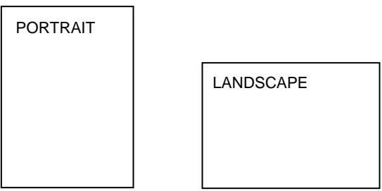
Fig. 4-4 Page Orientation
When you enter the setting mode, the display first shows the current orientation with an asterisk.
Press the ▲ or ▼ button until the desired orientation appears on the display.
| Display Message | Orientation |
| ORI=PORTRAIT | Portrait |
| ORI=LANDSCAPE | Landscape |
Press the Set button to make the displayed selection effective.
An asterisk appears at the end of the display for a short time. Then the printer automatically exits from the setting mode to the FORMAT MODE.
| Selection | LCD message on the upper row |
| portrait | LJ READY 001P T1 |
| landscape | LJ READY 001L T1 |
AUTO MODE
Note
The settings in this mode menu are effective in the HP PCL5C, EPSON FX-850 and IBM Proprinter XL modes. They do not appear in other emulation modes.
The page/line termination is set in this mode.
| Display Message | Setting | Auto Mode | ||
| AUTO | LF | =OFF | ON | CR → CR+LF |
| OFF | CR → CR | |||
| AUTO | CR | =OFF | ON | LF → LF+CR, FF → FF+CR, VT → VT+CR |
| OFF | LF → LF, FF → FF, VT → VT | |||
| AUTO | WRAP | =OFF | ON | Line feed and carriage return occur when the printer position reaches the right margin. |
| OFF | No line feed and carriage return occur when the printer position reaches the right margin. | |||
| AUTO | SKIP | =ON | ON | Form feed occurs when the printer position reaches the bottom margin. |
| OFF | No form feed occurs when the printer position reaches the bottom margin. | |||
| AUTO | MASK | =OFF | ON | The printer ignores the top and bottom margin settings you selected via the control panel. The page length is automatically set to 11” for letter or A4-size paper and to 14” for legal-size paper. |
| OFF | The printer operates according to the margin settings you selected via the control panel. | |||
Note on "AUTO MASK"
When you use application software in non-HP modes, be sure to set “AUTO MASK” to ON. When you use letter or A4 size paper, the top and bottom 2 lines are masked and they do not appear on the printout.
The auto modes are subject to the current emulation mode.
O : The auto modes can be set.
X : The auto modes cannot be changed and no setting appears.
— : The auto modes are not available.
| AUTO Mode | Printer Emulation (Factory settings in bold print) | ||
| HP | EPSON | IBM | |
| PCL5C | FX-850 | Proprinter XL | |
| AUTO LF | O OFF | O OFF | O OFF |
| AUTO CR | O OFF | X ON | O OFF (Note) |
| AUTO WRAP | O OFF | X ON | X ON |
| AUTO SKIP | O ON | — | — |
| AUTO MASK | — | O OFF | O OFF |
Note
In the IBM emulation mode, FF codes are always followed by a CR code.
PAGE FORMAT MODE
Notes
The settings in this mode menu will vary as follows:
- All settings are effective in the HP PCL5C, EPSON FX-850 and IBM Proprinter XL modes.
- The X and Y (vertical and horizontal) offsets are effective in the BRScript 2 mode. Other settings are not effective and they do not appear in this mode.
- The paper size and the X and Y (vertical and horizontal) offsets are effective in the HP-GL mode. Other settings are not effective and they do not appear in this mode.
The following settings can be made in this mode:
| Display Message | Page Format Mode |
| PAPER =LETTER | Set cut sheet paper size to letter, A4, legal, B5, A5 or executive, or envelope size to JIS B5, COM10 or DL. |
| LEFT M = 0C P | Set the left margin at column 0-126 at 10cpi. |
| RIGHT M = 80C P | Set the right margin at column 10-136 at 10cpi. See “List of Factory Settings” in this chapter. |
| TOP M =0.5" P | Set the top margin at a distance from the top edge of the paper: 0, 0.33 (Non-HP), 0.5 (HP), 1.0, 1.5, or 2.0 inches. |
| BOTTOM M=0.5" P | Set the bottom margin at a distance from the bottom edge of the paper: 0, 0.33 (Non-HP), 0.5 (HP), 1.0, 1.5, or 2.0 inches. |
| LINES = 60L P | Set the number of lines per page from 5 to 128 lines. See “List of Factory Settings” in this chapter. |
The letter “P” in the display messages indicates that the page orientation is portrait. The letter “L” is displayed when it is landscape.
| Display Message | Page Format Mode (Continued) | |
| X OFFSET= | 0 | Move the print start position (at the upper left corner on pages) horizontally up to -500 dots to the left or +500 dots to the right in 300dpi dot unit increments:factory setting = 0. |
| Y OFFSET= | 0 | Move the print start position (at the upper left corner on pages) vertically up to -500 dots downward or +500 dots upward in 300dpi dot increments:factory setting = 0. |
Notes
When you choose settings in PAGE FORMAT MODE, note the following:
- Letter size has been factory set for 120V models. A4 size has been factory set for 220/240V models.
- When you use paper smaller than specified in the PAGE FORMAT MODE, be sure that the print area is smaller than the paper size; otherwise the inside of the printer will get stained with toner. We recommend that you perform a test before actual use. For this test, you should use letter or A4 size of paper to confirm that the printed area is completely within the margins of the paper size you intend using. This simple test will help prevent toner from spreading throughout the inside of your printer, which may cause later print jobs to be smudged with toner.
- The factory settings for the right/left margins and lines vary according to the paper size and orientation. See the tables below.
- The top and bottom margins have been factory set to 0.5" in the HP emulation mode and to 0.33" in the non-HP emulation modes.
- The setting margins are subject to the current page orientation. The display shows the current orientation with “P” for portrait and “L” for landscape.
- Images offset outside the print area are not printed.
■ About Right and Left Margins
The settings range of the right and left margins are subject to the page orientation as follows. The right margin should be placed 10 columns greater than the left margin: minimum text width = 10 columns.
If the orientation is changed, the margin settings are restored to the factory settings. If the paper size is changed and the right and left margins exceed the paper size, they are restored to the factory settings: if they do not exceed the paper size, they remain effective.
The following table shows the range of settings in columns. The factory settings are printed in bold.
| Paper Size | Portrait | Landscape | ||
| Left Margin | Right Margin | Left Margin | Right Margin | |
| Letter | 0-70 | 10-80 | 0-96 | 10-106 |
| A4 | 0-70 | 10-78-80 | 0-103 | 10-113 |
| Legal | 0-70 | 10-80 | 0-126 | 10-136 |
■ About Line Settings
Setting the number of lines/page automatically sets the line spacing or line feed pitch. If the paper size is changed, the number of lines/page changes accordingly. The new setting is calculated with the following expression and the remainder, if any, is ignored. However, the line feed pitch and the top and bottom margins remain effective.
$$ # \text { of Lines / Page } = \frac {\text { Page Length - (Top Margin + Bottom Margin) }}{\text { Line Feed Pitch [Vertical Motion Index (VMI)] }} $$
The setting of lines/page is subject to the current paper size and orientation. For example, when letter-sized paper is used, the printer can print 60 lines per page in portrait orientation. If the orientation is changed, the line settings are restored to the factory settings in that orientation.
The following tables show the factory settings in each emulation mode.
In HP Mode
| Size | Orientation | |
| Portrait | Landscape | |
| Letter | 60 lines | 45 lines |
| A4 | 64 lines | 43 lines |
| Legal | 78 lines | 45 lines |
In Non-HP Modes
| Size | Orientation | |
| Portrait | Landscape | |
| Letter | 62 lines | 47 lines |
| A4 | 66 lines | 45 lines |
| Legal | 80 lines | 47 lines |
Note
When you use application software in the non-HP modes, the recommended settings are as follows:
• Left margin = column 0
• Right margin = Max. value
- Auto MASK ON
COLOR MODE
Note
The settings in this mode menu are effective only in the HP PCL5C and BR-Script 2 modes.
| Display Message | Orientation |
| COLOR PRINT=ON | print in color mode |
| COLOR PRINT=OFF | print in monochrome mode only |
GRAPHICS MODE
Note
The settings in this mode menu are effective only in the HP-GL mode.
They do not appear in any other emulation modes.
Since the HP-GL emulation mode is for a plotter, you can select the plotter pens, the pen size and percentage of gray in this mode menu.
| Display Message | Graphics Mode |
| PEN SETTING | Set the size and percentage of gray separately for six plotter pens. |
| CHARACTER SET | Set the standard and alternate character sets. |
Note
In most cases, the application software controls the above graphics mode settings, so you do not have to set them in this menu with the Mode button. The software or command setting overrides the button setting.
Select the setting menu and enter the sub-setting menu to make the changes as follows:
■ Pen Setting
After you select the pen, advance to the sub-setting menu for size or gray-percentage selection with the ▲ or ▼ button and enter the menu with the Set button.
| Message appears on the lower row of the LCD | What you can adjust |
| SIZE 1=3 dots * | The pen size can be set from 1 dot to 10 dots |
| GRAY 1=100% * | The shades of gray can be set to 15, 30, 45, 75, 90 or 100% |
Notes
- When another pen is selected, the display shows the selected pen with the number after “SIZE” or “GRAY.”
- Whichever resolution you have selected (300 or 600 dpi), the pen size takes effect in units of 300 dpi.
■ Character Set
When you select “CHARACTER SET,” you can select the standard and alternate character sets used in the HP-GL emulation mode.
Enter the sub-setting menu and select the menu for the standard or alternate character set with the ▲ or ▼ button and press the Set button.
| Character Set | Message on the lower row of the LCD panel |
| standard character set | STANDARD SET |
| alternate character set | ALTERNATE SET |
| Character Sets in HP-GL Emulation Mode |
| ANSI ASCII (Factory setting) |
| 9825 CHR. SET |
| FRENCH/GERMAN |
| SCANDINAVIAN |
| SPANISH/LATIN |
| JIS ASCII |
| ROMAN8 EXT. |
| ISO IRV |
| ISO SWEDISH |
| ISO SWEDISH:N |
| ISO NORWAY 1 |
| ISO GERMAN |
| ISO FRENCH |
| ISO U.K. |
| ISO ITALIAN |
| ISO SPANISH |
| ISO PORTUGUESE |
| ISO NORWAY 2 |
RESOLUTION MODE
The print resolution, Color Advanced Photoscale Technology (CAPT) and High Resolution Control (HRC) can be set in this mode menu.
| Display Message | Resolution Mode |
| RESOLUTION | Set the print resolution of the printer. |
| CAPT SETTING | Set the CAPT function. . |
| HRC SETTING | Set the HRC function. |
Select the setting menu and enter the sub-setting menu to make the settings as follows:
■ Resolution
When you select “RESOLUTION,” you can choose a resolution of 300 or 600 dots per inch (dpi) on this printer. You can set the resolution in this mode according to your requirements.
The printer may not be able to print large files because of the resolution and the printer's memory. The higher the resolution (and thus the file size), the more memory is required.
| Display Message | Resolution |
| RESOLUTION=600 | Set the resolution to 600 dpi.(Factory setting) |
| RESOLUTION=300 | Set the resolution to 300 dpi. |
Note
- Even if you set the resolution to 600 dpi in this mode, the printer may not be able to print large and complex full color files at 600 dpi because of insufficient memory. However, it automatically decreases the resolution to 300 dpi to print them. While the printer is printing in this mode, the display prompts “01 PR300 ...”
- If the printer cannot print files even at 300 dpi, a “MEMORY FULL” error occurs. See “TROUBLESHOOTING” in Chapter 6.
- This automatic resolution decrease function works with the page protection on. See also “PAGE PROTECTION” in this chapter.
- When you want to print large and complex full color data without decreasing the resolution, you should expand the memory capacity of the printer.
■ CAPT Setting
When you select “CAPT SETTING,” you can use the Color Advanced Photoscale Technology (CAPT) function which offers photographic fine color on graphics. CAPT setting is available only in BR-Script 2 mode. This feature requires a minimum of 24 MB of RAM to process large and complex full color printouts. When you set CAPT=ON, the high resolution control (HRC) setting is unavailable.
| Display Message | Advanced Photoscale Technology |
| CAPT =ON | Color advanced photoscale technology is effective. |
| CAPT =OFF | Cancel the color advanced photoscale technology. (factory setting) |
Note
In the PCL 5C mode, CAPT setting is always ON. It depends on the printer setting if the printer uses the function or not.
■ HRC Setting
When you select “HRC SETTING,” you can set the high resolution control (HRC) function which is a special function that offers improved print quality of characters and graphics that conventional laser printers cannot attain with resolutions of 300 or 600 dpi.
| Display Message | High Resolution Control |
| HRC =OFF | Cancel high resolution control. |
| HRC =LIGHT | Set high resolution control to the light level. |
| HRC =MEDIUM | Set high resolution control to the medium level. (Factory setting) |
| HRC =DARK | Set high resolution control to the dark level. |
The following figures show jagged print with the high resolution control set to “OFF” on the left and clear and crisp print with the control set to “MEDIUM” on the right.

natural_image
Simple line drawing of a speech bubble with a curved black line inside, no text or symbols present.ABC
HRC = OFF

natural_image
Simple black speech bubble icon with curved line inside, no text or symbols presentABC
HRC = MEDIUM
Fig. 4-5 High Resolution Control
The high resolution control has been factory set to “MEDIUM.” The “LIGHT” or “DARK” setting might be better depending on the selected print density. Choose the best setting for clear and crisp printouts.
To check the printout with the high resolution control, perform the test print with the Test button. For operation information, see “TEST Button.”
Lines in the test pattern are smoother if the high resolution control is set to LIGHT, MEDIUM, or DARK. Choose an HRC setting and perform the test print so that stepped lines become unnoticeable.
natural_image
Diagram showing a square with horizontal lines and a magnified inset of a textured pattern (no text or symbols)HRC = OFF
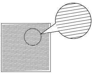
natural_image
Diagram showing a square with horizontal lines and a circle of radius pointing to its top-right corner (no text or symbols)HRC = MEDIUM
Fig. 4-6 High Resolution Control in Test Printout
PAGE PROTECTION
Note
The setting in this mode menu is effective in the HP PCL5C, EPSON FX-850, IBM Proprinter XL and HP-GL modes. It does not appear in the BRScript 2 mode.
If print images are too complex to print, the printer may print them in parts or only on part of the page. If this occurs, the printer loses print data and shows a message on the LCD panel.
The page protection function reserves additional memory so that the printer can create the entire page image in memory before physically printing it. This function can be set for letter, A4, or legal size paper. Select the paper size for page protection.
| Display Message | Page Protection |
| PROTECT=AUTO | Page protection on only when it is necessary. (Factory setting) |
| PROTECT=LETTER | Page protection on for letter size paper. |
| PROTECT=A4 | Page protection on for A4 size paper. |
| PROTECT=LEGAL | Page protection on for legal size paper. |
| PROTECT=OFF | Page protection off |
To protect pages, your printer will need the minimum memory shown in the following table:
| Protection | 600 dpi Color |
| Off | 16 Mbytes |
| Letter or A4 | 20 Mbytes |
| Legal | 24 Mbytes |
Note
When you use the page protection function, note the following:
- If the function setting is changed, all download fonts and macros—including permanent ones—are cleared. If the memory is too low to protect pages, page protection does not take effect.
DEVICE OPERATION
Notes
- BE SURE TO TURN OFF THE PRINTER POWER BUTTON BEFORE INSTALLING OR REMOVING A FLASH MEMORY CARD OR HDD CARD, OR THE CARD WILL BE DAMAGED.
- Settings in this mode are effective only when you have installed a flash memory card, HDD card or optional HDD and you have selected PCL5C, HP-GL, or BR-Script 2. They will not appear if the printer does not have a card installed or if it is in another emulation mode.
- If you turn the printer off or remove the flash memory card or HDD card while data is being written onto or deleted from the card, all the data on the card may be lost.
- If the write protect button of the flash memory card or HDD card is on, this mode menu does not appear.
• An HDD card will only fit into slot 2.
Be sure to install a commercial flash memory card or HDD card in the correct card slot of the printer.
When you are in this mode menu, you can save macros and fonts in the installed flash memory card or the HDD card.
The sub-setting menus displayed in this mode will vary according to the status of the installed card.
| Display Message | Card Operation |
| DEVICE 1 | Select Card 1. |
| DEVICE 2 | Select Card 2. |
| DEVICE 3 | Select optional HDD. |
When two cards are installed, you can select the card that you want to operate.
When the installed card is not formatted:
When you enter this mode menu with a flash memory card, HDD card or optional HDD installed but not formatted by this printer, you must first format the device.
If DEVICE is selected,
| Display Message | Card Operation |
| FORMAT DEVICE | Format a new flash memory card, HDD card or optional HDD. |
| Exit | Exit to DEVICE OPERATION |
When the display shows “FORMAT DEVICE,” press the Set button to format the installed card.
After the printer finishes formatting the device, you must exit to the “DEVICE OPERATION” menu.
Notes
- When the card is formatted, data that was previously written is erased.
- It takes ten or more seconds to format a 2-Mbyte flash memory card, HDD card or optional HDD. The larger the capacity of the device, the longer time it takes to format.
When the installed flash memory card, HDD card or optional HDD is formatted:
When you enter this mode menu with a formatted device installed, the display shows the following menus:
| Display Message | Card Operation |
| DEVICE 1 | Select Card 1. |
| DEVICE 2 | Select Card 2. |
| DEVICE 3 | Select optional HDD. |
After you have selected the card, the display shows the following messages:
| Display Message | Flash Operation |
| EXECUTE DATA | Select the data ID and execute the selected data. This menu appears only when data has been saved on the card. |
| DEVICE LIST | Print the contents of the flash memory, HDD card or optional HDD. This menu appears only when something has been saved in the device. |
| SAVE | Save received data, macros and fonts. |
| DELETE | Delete items from the device. |
Note
A common use of the flash memory is with FORMS software packages. With these commercially available software packages you have an option to send a form to the printer without any data. After you have sent the form to the printer, you may save the form in the flash memory as a Macro. Then the next time you want to print this form, you would setup your FORMS software package to SEND DATA ONLY - USE FORM IN PRINTER. This process could save from 1 to 4 minutes per print job.
Select the setting menu and enter the sub-setting menu to change the settings as follows:
■ Execute Data
Note
This menu appears only when data has been saved on the device.
When you select “EXECUTE DATA,” you can execute any of the data saved in the device using the SAVE DATA mode.
When you enter this sub-setting menu with the Set button, the printer prompts you to select the ID of the data.
Select the ID with the ▲ or ▼ button and press the Set button again, so that the printer executes the selected data.
■ Device List
When you select “DEVICE LIST” and you press the Set button, the printer automatically loads paper and starts printing the contents of the installed flash memory card, HDD card or optional HDD. You can check the contents and the unused capacity of the device.
■ Save
When you select “SAVE” and you press the Set button, you can enter the following sub-setting menus to save the macros and fonts in the installed device:
| Display Message | Save Menu |
| SAVE DATA | Save data that the printer will receive and set its ID. |
| SAVE MACRO | Save a macro. This menu appears only in the HP PCL5C emulation mode. |
| PRIMARY FONT | Save the primary font selected with the Font button. This menu appears only in the HP PCL5C emulation mode. |
| SECONDARY FONT | Save the secondary font selected with the Font button. This menu appears only in the HP PCL5C emulation mode. |
| DOWNLOAD FONT | Save a download font. This menu appears only in the HP PCL5C emulation mode. |
Note
If the capacity of the device becomes low while macros and fonts are being saved, the display shows the “DEVICE FULL” error message and they cannot be saved. Use a new device or delete unnecessary macros and fonts from the card. The DEVICE LIST displays the contents and the used capacity.
- Save Data
You can send data and save it on the device. In this mode, any kind of data such as PCL data, BR-Script 2 data and command strings can be saved. When you select “SAVE DATA” and you press the Set button, the display shows the guide menu.
The guide menu message prompts you to press the Set button again so that the printer exits from the data reception status when you have finished sending data.
Send the data from your computer and then press the Set button.
Notes
When you send data to be saved on the card, it is temporarily stored in the RAM of the printer. Note the following:
- If the received data exceeds the RAM capacity, a memory full error occurs. You can clear this error with the Continue button. When this error occurs, only part of the image has been stored in RAM, therefore, you cannot save the data to the card.
- The printer is reset to ensure as much capacity as possible is available in RAM. If any data remains, it will be printed first.
After you have finished sending data, press the Set button again, so that the printer exits from the data reception status.
When you exit from the data reception status, select the data ID with the
▲ or ▼ button and press the Set button. The printer will then save the received data with the selected ID onto the card.
Notes
- When you see an asterisk on the display, the ID number has been used for other data or a macro. If you select the used ID number, the old data or macro is erased and replaced with the new data.
- Once the data is saved, you can execute it with “EXECUTE DATA” or with a data execution command.
- The data saved in the SAVE DATA mode cannot be run with a macro execution command in HP PCL5C emulation.
- Save Macro
Note
The “SAVE MACRO” menu appears only in the HP PCL5C emulation mode.
If you have downloaded a macro into the printer's memory, you can save the macro on the installed flash memory card or HDD card.
If a macro has been downloaded into the printer's memory and you press the Set button at "SAVE MACRO", the printer prompts you to select the ID for the macro.
Select the ID with the ▲ or ▼ button and press the Set button again, so that the printer saves the macro with the selected ID.
Note
When you see an asterisk on the display, the ID number has been used for another macro or data. If you select the used ID number, the old macro or data is erased and replaced with the new macro.
You can execute a macro with the macro execution command.
• Primary Font or Secondary Font
Note
The “PRIMARY FONT” and “SECONDARY FONT” menus appear only in the HP PCL5C emulation mode.
If you have selected the primary or secondary font with the Font button, you can save the font on the installed flash memory card or HDD card.
When you press the Set button at the “PRIMARY FONT” or “SECONDARY FONT” message, the printer prompts you to select the ID of the font.
Select the ID with the ▲ or ▼ button and press the Set button again, so that the printer saves the font with the selected ID.
Note
When you see an asterisk on the display, the ID number has been used for another font. If you select the used ID number, the old font will be erased and replaced with the new one.
Whatever font you have selected via the Font button, the printer will save it as a bitmapped font as long as the print size is no more than 24 point. This allows the printer to print fonts faster than when they are not saved. We recommend that you save the scalable fonts that you frequently use as bitmap fonts for faster printing.
Since the flash memory card is in card slot 1 or 2 (the HDD card can only be used in card slot 2), fonts stored in the card behave in the same way as they would if they were in a dedicated Font Card. You can select the saved fonts as “DEVICE1 FONT” or “DEVICE2 FONT” with the Font button or the font selection command from your software. For font selection, see “FONT Button” in this chapter.
You can check the saved fonts by printing the list of fonts with the Test button. See “TEST Button” in this chapter.
Notes
When you save the primary or secondary font, note the following:
- The font is temporarily stored in the RAM of the printer before it is saved on the device. If the font data exceeds the RAM capacity, a memory full error occurs. You can clear this error with the Continue button. As not all the font data has been stored in RAM, you cannot save the font to the device. When the font data is saved, the printer is reset to ensure as much capacity as possible in RAM. If any data remains, it is printed.
- If you have saved the font at 600-dpi resolution and change the printer resolution to 300 dpi, the printer cannot print the saved font.
- Download Font
Notes
- The “DOWNLOAD FONT” menu appears only in the HP PCL5C emulation mode.
- Be sure to print the list of download fonts with the Test button and check the download font ID on the list before you enter this menu. You must select the font in this menu using the same number you see on the list.
If you have downloaded a font into the printer memory, you can save it on the flash memory card, HDD card or optional HDD.
The printer prompts you to select the download font ID that you can choose from the font list. Press the ▲ or ▼ button to move the cursor to the ID and select it with the Set button.
Note
The download font IDs do not appear when fonts have not been downloaded.
After you have selected the download font ID, press the Set button, so that the printer saves the selected download font. Vector or bitmapped fonts are saved in the format of the original font.
Once you save the downloaded font in the device, you will not need to download the font every time you want to use it.
Since the font can be saved in either the flash memory card in card slot 1 or 2 (the HDD card can be used only in card slot 2) of the printer, or in the optional HDD, you can select the saved fonts as “DEVICE1(2 or 3) FONT” with the Font button or the font selection command from your software. For font selection, see “FONT Button” in this chapter.
You can check the fonts saved on the card by printing the list of fonts with the Test button. See “TEST Button” in this chapter.
Note
When the fonts on the HDD card are selected in a print job, they are copied into the printer RAM. It may cause a printer memory full error because those fonts occupy some RAM space. We recommend that you install optional DIMM memory to use the downloaded fonts on the HDD card.
Delete
When you select “DELETE” and press the Set button, you can enter the following sub-setting menus to delete macros and fonts or format the installed flash memory card or HDD card:
| Display Message | Delete Menu |
| MACRO ID=##### | Delete the selected ID macro. |
| DATA ID=##### | Delete the selected ID data. |
| FONT ID=##### | Delete the selected ID font. |
| FORMAT DEVICE | Format the flash memory card, HDD card or optional HDD. |
- Macro
When you press the Set button at “MACRO ID=#####,” the cursor moves to the ID number. The printer prompts you to select the ID number of the macro to be deleted.
Select the ID number with the ▲ or ▼ button and press the Set button, so the printer deletes the selected macro.
- Data
When you press the Set button at "DATA ID=#####," the cursor moves to the ID number. The printer prompts you to select the ID number of the data to be deleted.
Select the ID number with the ▲ or ▼ button and press the Set button, so the printer deletes the selected data.
- Font
When you press the Set button at "FONT ID=#####," the cursor moves to the ID number. The printer prompts you to select the ID number of the font to be deleted.
Select the ID number with the ▲ or ▼ button and press the Set button, so the printer deletes the selected font.
- Format Device
You can format the flash memory card, HDD card or optional HDD to delete its contents. Instructions are in the following menu:
FORMAT DEVICE
When you press the Set button in this menu, the printer asks if you want to delete all contents of the device. Then press the Set button to start formatting the device.
When you want to cancel formatting, move to the next menu with the ▲ or ▼ button and press the Set button.
ADVANCED MODE
NETWORK MODE
| Display Message | Network Mode |
| LOCK PANEL=OFF | Turns on or off lock panel function. |
| AUTO FF=ON | Turns on or off auto form feed. |
| FF SUPPRESS=OFF | Turns on or off the form feed suppress function. |
■ Lock panel
If someone other than you has changed the control panel settings and you do not know about it, the printer may not print as expected or it may not print at all.
To address this problem, lock or unlock the control panel as follows:
| Display Message | Lock Panel |
| LOCK=OFF | Unlock the panel buttons of the printer. (Factory setting) |
| LOCK=ON | Lock the panel buttons of the printer. |
Even if the control panel is locked, you can still use the Sel, Form Feed, Copy, Continue, Reset and Test buttons for their standard functions. You can only check the settings of the other buttons, you cannot make changes to them.. To change these settings you must first unlock the control panel.
To lock or unlock the control panel, you must enter a 3-digit pass number.
The default setting is OFF. To turn on the lock feature, select the ON setting and press Set. Change the first digit of the number with the ▲ or
▼ button and move to the next digit with the Set button. After you finish entering your 3-digit pass number, the control panel buttons are now locked. To unlock the settings, change the Lock setting to OFF on the control panel and then enter the 3 digit code you previously entered. Correct entry is required for the setting to be unlocked.
Note
Do not forget the pass number used to lock the control panel. If you enter the wrong number, you will not be able to unlock it and the display will show the following message:
INCORRECT!!
■ Auto Form Feed
If unprinted data remains in the printer's memory, the Data LED stays on. You must print the remaining data with the Form Feed button. See “FORM FEED Button” in this chapter.
The auto form feed mode you can set in this menu allows you to print the remaining data without pressing the Form Feed button.
You can turn the auto form feed mode on or off in this menu as follows:
| Display Message | Auto Form Feed |
| AUTO FF=OFF | Turn off the auto form feed. You must press the Form Feed button every time data remains in the printer's memory. (Factory setting) |
| AUTO FF=ON | Turn on the auto form feed. Every time data remains in the printer's memory, an auto form feed takes place after the wait time set as shown below. |
When you turn on the auto form feed feature as explained above, you must set the wait time in the following sub-setting menu:
| Display Message | Wait Time |
| WAIT TIME= 1s | Set the wait time for the auto form feed. The printer automatically prints the remaining data after the set wait time. |
| WAIT TIME=99s | The wait time can be set from 1 to 99 seconds. |
■ Form Feed Suppress
You can turn the form feed suppress function on or off in this menu as follows:
| Display Message | Form Feed Suppress |
| FF SUPPRESS=OFF | Turn off the form feed suppress function. (Factory setting) |
| FF SUPPRESS=ON | Turn on the form feed suppress function. |
If pages contain no print data, the printer would normally print blank pages. When you turn this function on, you can suppress printing blank pages.
When the printer is used in a network environment, it may be set to deliberately print a blank page at the end of each print job. When you turn on this function, the printer does not print the blank pages.
ERROR PRINT
Note
The setting in this mode menu is effective only in the BR-Script 2 mode. It does not appear in any other emulation modes.
You can turn on or off the error print in this mode.
| Display Message | Error Mode |
| ERROR PRINT=ON | Turn on the error print so that the printer prints a Postscript error if one occurs. |
| ERROR PRINT=OFF | Turn off the error print so that the printer does not print an error message. (Factory setting) |
CONTINUE MODE
If any recoverable error occurs, including “Toner Empty,” it can be cleared with the Continue button. The Continue button function is selected with this mode setting.
| Display Message | Continue Mode |
| CONTINUE=MANUAL | Select the manual error recovery mode. Press the Continue button to clear errors. (Factory setting) |
| CONTINUE=AUTO | Select the auto error recovery mode. The printer automatically clears recoverable errors. You need not press the Continue button. |
SCALABLE FONT

Note
The setting in this mode menu is effective only in the HP PCL5C mode. It does not appear in any other emulation modes.
Since this printer has many scalable fonts, some application programs may not be able to handle them correctly. When the HP PCL5C emulation mode has been selected, the printer may print a different font rather than the font you have selected with your program or a font selection command.
To cope with this font problem, you can restrict the font selection by using this setting as follows:
| Display Message | Scalable Font |
| FONT=ALL | All scalable fonts for this printer can be selected with the font selection command. (Factory setting) |
| FONT=LJ | Scalable fonts for this printer other than the following can be selected with the font selection command: Atlanta, Bermuda Script, PC Brussels, Copenhagen, Germany, Portugal, Calgary, San Diego, and US Roman. |
Even if you restrict the font selection as above, you can select among all the scalable fonts with the Font button. The setting in this mode menu merely restricts the font selection command from an application to avoid incorrect font selections.
INPUT BUFFER
You can increase or decrease the capacity of the input buffer with the ▲ or ▼ button in this mode menu. A larger capacity allows the printer to receive data from the computer faster.
Note
If the printer reports a memory full error, reduce the capacity of the input buffer.
| Display Message | Input Buffer |
| ☐☐☐☐☐☐☐☐☐☐☐☐☐☐☐☐☐☐☐☐☐☐☐☐☐☐☐☐☐☐☐☐☐☐☐☐☐☐☐☐☐☐☐☐☐☐☐☐☐☐☐☐☐☐☐☐☐☐☐☐☐☐☐☐☐☐☐☐☐☐☐☐☐☐☐☐☐☐☐☐☐☐☐☐☐☐☐☐☐☐☐☐☐☐☐☐☐☐☐☐ ☐☐☐☐☐☐☐☐☐☐☐☐☐☐☐☐☐☐☐☐☐☐☐☐☐☐☐☐☐☐☐☐☐☐☐☐☐☐☐☐☐☐☐☐☐☐☐☐☐☐☐☐☐☐☐☐☐☐☐☐☐☐☐☐☐☐☐☐☐☐☐☐☐☐☐☐☐☐☐☐☐☐☐☐☐☐☐☐☐☐☐☐☐☐☐☐☐☐☐☐□☐☐☐☐☐☐☐☐☐☐☐☐☐☐☐☐☐☐☐☐☐☐☐☐☐☐☐☐☐☐☐☐☐☐☐☐☐☐☐☐☐☐☐☐☐☐☐☐☐☐☐☐☐☐☐☐☐☐☐☐☐☐☐☐☐☐☐☐☐☐☐☐☐☐☐☐☐☐☐☐☐☐☐☐☐☐☐☐☐☐☐☐☐☐☐☐☐☐☐☑☐☐☐☐☐☐☐☐☐☐☐☐☐☐☐☐☐☐☐☐☐☐☐☐☐☐☐☐☐☐☐☐☐☐☐☐☐☐☐☐☐☐☐☐☐☐☐☐☐☐☐☐☐☐☐☐☐☐☐☐☐☐☐☐☐☐☐☐☐☐☐☐☐☐☐☐☐☐☐☐☐☐☐☐☐☐☐☐☐☐☐☐☐☐☐☐☐☐☐☒☐☐☐☐☐☐☐☐☐☐☐☐☐☐☐☐☐☐☐☐☐☐☐☐☐☐☐☐☐☐☐☐☐☐☐☐☐☐☐☐☐☐☐☐☐☐☐☐☐☐☐☐☐☐☐☐☐☐☐☐☐☐☐☐☐☐☐☐☐☐☐☐☐☐☐☐☐☐☐☐☐☐☐☐☐☐☐☐☐☐☐☐☐☐☐☐☐☐☐○☐☐☐☐☐☐☐☐☐☐☐☐☐☐☐☐☐☐☐☐☐☐☐☐☐☐☐☐☐☐☐☐☐☐☐☐☐☐☐☐☐☐☐☐☐☐☐☐☐☐☐☐☐☐☐☐☐☐☐☐☐☐☐☐☐☐☐☐☐☐☐☐☐☐☐☐☐☐☐☐☐☐☐☐☐☐☐☐☐☐☐☐☐☐☐☐☐☐☐口 ☐☐☐☐☐☐☐☐☐☐☐☐☐☐☐☐☐☐☐☐☐☐☐☐☐☐☐☐☐☐☐☐☐☐☐☐☐☐☐☐☐☐☐☐☐☐☐☐☐☐☐☐☐☐☐☐☐☐☐☐☐☐☐☐☐☐☐☐☐☐☐☐☐☐☐☐☐☐☐☐☐☐☐☐☐☐☐☐☐☐☐☐☐☐☐☐☐☐ ☐ ☐ ☐ ☐ ☐ ☐ ☐ ☐ ☐ ☐ ☐ ☐ ☐ ☐ ☐ ☐ ☐ ☐ ☐ ☐ ☐ ☐ ☐ ☐ ☐ ☐ ☐ ☐ ☐ ☐ ☐ ☐ ☐ ☐ ☐ ☐ ☐ ☐ ☐ ☐ ☐ ☐ ☐ ☐ ☐ ☐ ☐ ☐ ☐ ☐ ☑ ☐ ☐ ☐ ☐ ☐ ☐ ☐ ☐ ☐ ☐ ☐ ☐ ☐ ☐ ☐ ☐ ☐ ☐ ☐ ☐ ☐ ☐ ☐ ☐ ☐ ☐ ☐ ☐ ☐ ☐ ☐ ☐ ☐ ☐ ☐ ☐ ☐ ☐ ☐ ☐ ☐ ☐ ☐ ☐ ☐ ☐ ☐ ☐ ☐ ☒ ☐ ☐ ☐ ☐ ☐ ☐ ☐ ☐ ☐ ☐ ☐ ☐ ☐ ☐ ☐ ☐ ☐ ☐ ☐ ☐ ☐ ☐ ☐ ☐ ☐ ☐ ☐ ☐ ☐ ☐ ☐ ☐ ☐ ☐ ☐ ☐ ☐ ☐ ☐ ☐ ☐ ☐ ☐ ☐ ☐ ☐ ☐ ☐ ☐ ☓ ☐ ☐ ☐ ☐ ☐ ☐ ☐ ☐ ☐ ☐ ☐ ☐ ☐ ☐ ☐ ☐ ☐ ☐ ☐ ☐ ☐ ☐ ☐ ☐ ☐ ☐ ☐ ☐ ☐ ☐ ☐ ☐ ☐ ☐ ☐ ☐ ☐ ☐ ☐ ☐ ☐ ☐ ☐ ☐ ☐ ☐ ☐ ☐ ☐ ★ ☐ ☐ ☐ ☐ ☐ ☐ ☐ ☐ ☐ ☐ ☐ ☐ ☐ ☐ ☐ ☐ ☐ ☐ ☐ ☐ ☐ ☐ ☐ ☐ ☐ ☐ ☐ ☐ ☐ ☐ ☐ ☐ ☐ ☐ ☐ ☐ ☐ ☐ ☐ ☐ ☐ ☐ ☐ ☐ ☐ ☐ ☐ ☐ ☐ ☎ ☐ ☐ ☐ ☐ ☐ ☐ ☐ ☐ ☐ ☐ ☐ ☐ ☐ ☐ ☐ ☐ ☐ ☐ ☐ ☐ ☐ ☐ ☐ ☐ ☐ ☐ ☐ ☐ ☐ ☐ ☐ ☐ ☐ ☐ ☐ ☐ ☐ ☐ ☐ ☐ ☐ ☐ ☐ ☐ ☐ ☐ ☐ ☐ ☐ ☶ ☐ ☐ ☐ ☐ ☐ ☐ ☐ ☐ ☐ ☐ ☐ ☐ ☐ ☐ ☐ ☐ ☐ ☐ ☐ ☐ ☐ ☐ ☐ ☐ ☐ ☐ ☐ ☐ ☐ ☐ ☐ ☐ ☐ ☐ ☐ ☐ ☐ ☐ ☐ ☐ ☐ ☐ ☐ ☐ ☐ ☐ ☐ ☐ ☐ ☽ ☐ ☐ ☐ ☐ ☐ ☐ ☐ ☐ ☐ ☐ ☐ ☐ ☐ ☐ ☐ ☐ ☐ ☐ ☐ ☐ ☐ ☐ ☐ ☐ ☐ ☐ ☐ ☐ ☐ ☐ ☐ ☐ ☐ ☐ ☐ ☐ ☐ ☐ ☐ ☐ ☐ ☐ ☐ ☐ ☐ ☐ ☐ ☐ ☐ ☋ ☐ ☐ ☐ ☐ ☐ ☐ ☐ ☐ ☐ ☐ ☐ ☐ ☐ ☐ ☐ ☐ ☐ ☐ ☐ ☐ ☐ ☐ ☐ ☐ ☐ ☐ ☐ ☐ ☐ ☐ ☐ ☐ ☐ ☐ ☐ ☐ ☐ ☐ ☐ ☐ ☐ ☐ ☐ ☐ ☐ ☐ ☐ ☐ ☐ ☃ ☐ ☐ ☐ ☐ ☐ ☐ ☐ ☐ ☐ ☐ ☐ ☐ ☐ ☐ ☐ ☐ ☐ ☐ ☐ ☐ ☐ ☐ ☐ ☐ ☐ ☐ ☐ ☐ ☐ ☐ ☐ ☐ ☐ ☐ ☐ ☐ ☐ ☐ ☐ ☐ ☐ ☐ ☐ ☐ ☐ ☐ ☐ ☐ ☐ ☜ ☐ ☐ ☐ ☐ ☐ ☐ ☐ ☐ ☐ ☐ ☐ ☐ ☐ ☐ ☐ ☐ ☐ ☐ ☐ ☐ ☐ ☐ ☐ ☐ ☐ ☐ ☐ ☐ ☐ ☐ ☐ ☐ ☐ ☐ ☐ ☐ ☐ ☐ ☐ ☐ ☐ ☐ ☐ ☐ ☐ ☐ ☐ ☐ ☐ ☞ ☐ ☐ ☐ ☐ ☐ ☐ ☐ ☐ ☐ ☐ ☐ ☐ ☐ ☐ ☐ ☐ ☐ ☐ ☐ ☐ ☐ ☐ ☐ ☐ ☐ ☐ ☐ ☐ ☐ ☐ ☐ ☐ ☐ ☐ ☐ ☐ ☐ ☐ ☐ ☐ ☐ ☐ ☐ ☐ ☐ ☐ ☐ ☐ ☐ ☉ ☐ ☐ ☐ ☐ ☐ ☐ ☐ ☐ ☐ ☐ ☐ ☐ ☐ ☐ ☐ ☐ ☐ ☐ ☐ ☐ ☐ ☐ ☐ ☐ ☐ ☐ ☐ ☐ ☐ ☐ ☐ ☐ ☐ ☐ ☐ ☐ ☐ ☐ ☐ ☐ ☐ ☐ ☐ ☐ ☐ ☐ ☐ ☐ ☐ ☸ ☐ ☐ ☐ ☐ ☐ ☐ ☐ ☐ ☐ ☐ ☐ ☐ ☐ ☐ ☐ ☐ ☐ ☐ ☐ ☐ ☐ ☐ ☐ ☐ ☐ ☐ ☐ ☐ ☐ ☐ ☐ ☐ ☐ ☐ ☐ ☐ ☐ ☐ ☐ ☐ ☐ ☐ ☐ ☐ ☐ ☐ ☐ ☐ ☐ ☔ ☐ ☐ ☐ ☐ ☐ ☐ ☐ ☐ ☐ ☐ ☐ ☐ ☐ ☐ ☐ ☐ ☐ ☐ ☐ ☐ ☐ ☐ ☐ ☐ ☐ ☐ ☐ ☐ ☐ ☐ ☐ ☐ ☐ ☐ ☐ ☐ ☐ ☐ ☐ ☐ ☐ ☐ ☐ ☐ ☐ ☐ ☐ ☐ ☐ ☦ | |
After you change the input buffer capacity (make sure you press the Set button), be sure to turn off the printer and then turn it on again. The setting takes effect when you turn the printer back on.
Notes
- The set capacity is not changed even if the emulation mode is changed.
- The actual capacity of the input buffer varies according to the installed RAM. If the RAM capacity is small, the input buffer capacity may not be increased.
| Installed memory | 16M | 32M | 112M |
| 1 square | 30KB | 30KB | 30KB |
| 5 squares | 0.9MB | 4.3MB | 21.4MB |
| 15 squares | 3.0MB | 15.0MB | 75.0MB |
The Input buffer size increases proportionally.
Fig. 4-7 Input buffer size
SAVE SETTINGS
Suppose you share this printer with others who want different control panel settings.
Since more than one set of user settings can be stored in the printer's memory, you can easily reset the printer to your preferred settings after they are changed. For resetting the printer, see “RESET Button” in this chapter.
Use the control panel to set the configuration of the printer to meet your needs and then enter this mode menu to save your settings. Two sets of user settings can be saved in the printer as follows:
| Display Message | User Setting |
| SAVE SETTING 1 | Save the current settings as No. 1 in the printer’s memory. |
| SAVE SETTING 2 | Save the current settings as No. 2 in the printer’s memory. |
If you want to check the user settings, you can print a list of the settings with the Test button. See “TEST Button” in this chapter.

Note
No user settings have been factory set.
TIME SETTINGS
A Real time clock is built into this printer. You can set the time in this mode.
| Display Message | User Setting |
| TIME SETTING | Set the time. |
| TIME STYLE | Set the time style shown on the display. |
| SUMMER TIME | Set summer time. |
| TIME ZONE | Set time zone. |
Please refer to the following chart when you want to set the Time Zone.
| - 12.0 | Eniwetok, Kwajalein |
| - 11.0 | Midway Island, Samoa |
| - 10.0 | Hawaii |
| - 9.0 | Alaska |
| - 8.0 | Pacific time (US & Canada) |
| - 7.0 | Mountain time (US & Canada), Arizona |
| - 6.0 | Central time (US & Canada), Mexico City, Saskatchewan |
| - 5.0 | Eastern time (US & Canada), Bogota, Lima |
| - 4.0 | Atlantic (Canada), Caracas, La Paz |
| - 3.5 | Newfoundland |
| - 3.0 | Brasilia, Buenos Aires, Georgetown |
| - 2.0 | Mid-Atlantic |
| - 1.0 | Azores, Cope Verde Is. |
| 0.0 | Greenwich Mean Time, Dublin, Edinburgh, London, Monrovia, Casablanca |
| + 1.0 | Berlin, Stockholm, Rome, Bern, Brussels, Vienna, Amsterdam, Paris, Madrid, Prague, Bratislava, Warsaw |
| + 2.0 | Athens, Helsinki, Istanbul, Cairo, Eastern Europe, Harare, Pretoria, Israel |
| + 3.0 | Baghdad, Kuwait, Nairobi, Riyadh, Moscow, St. Petersburg |
| + 3.5 | Tehran |
| + 4.0 | Abu Dhabi, Muscat, Tbilisi, Kazan, Volgograd |
| + 4.5 | Kabul |
| + 5.0 | Islamabad, Karachi, Ekaterinburg, Tashkent |
| + 5.5 | Bombay, Calcutta, Madras, New Delhi, Colombo |
| + 6.0 | Almaty, Dhaka |
| + 7.0 | Bangkok, Jakarta, Hanoi |
| + 8.0 | Beijing, Chongqing, Urumqi, Hong Kong, Perth, Singapore, Taipei |
| + 9.0 | Tokyo, Osaka, Sapporo, Seoul, Yakutsk |
| + 9.5 | Adelaide, Darwin |
| + 10.0 | Brisbane, Canberra, Melbourne, Sydney, Guam, Port Moresby, Vladivostok, Harare |
| + 11.0 | Magadan, Solomon Is., New Caledonia |
| + 12.0 | Fiji, Kamchatka, Marshall Is., Wellington, Auckland |
PAGE COUNTER
You can check the total number of printed pages with this mode. When you enter this mode, the display shows the number for a short time and then automatically moves to “exit MODE” menu.
EXIT MODE
When you finish setting your desired option in the mode menus, advance to the following message:
MODE exit MODE
Press the Set button to exit from the mode menus to the off-line ready state.
Note
Remember that you can exit from the mode menu at any time with the Sel button. After you make a setting effective with the Set button, press the Sel button. You will exit from the mode menu to the on-line ready state. The settings you have changed with the Set button are effective after a quick exit.
FONT Button
Pressing the Font button allows you to select fonts and symbol/character sets.
Notes
When you use the Font button, note the following:
- The Font button is effective in the HP PCL5C, EPSON FX-850, and IBM Proprinter XL modes. However the settings are subject to the current emulation mode. Note that the Font button does not work in the BR-Script 2 mode.
- If the application software supports font and symbol/character set selection, you do not need to set them with the Font button. The software or command setting overrides the button setting.
- If you want to use optional fonts instead of the printer's resident fonts, be sure to install a font cartridge/card that has your preferred fonts. The printer automatically selects the font that has exactly the same or similar characteristics as those you set through the software or with a command. If the installed font cartridge/card happens to have a font of similar characteristics, the printer will print with an unexpected font.
- You can store the fonts you require on a flash memory card or HDD card only in the HP PCL5C mode or BR-Script 2 mode when a card is installed. See “DEVICE OPERATION.”
Setting the Font and Symbol Set in the HP PCL5C Mode
When the HP PCL5C emulation mode has been selected, the font and symbol set can be set separately as the primary or secondary font.
When the primary font is selected;
| Message | To do: |
| SELECT FONT P | Set the primary font |
| SYMBOL SET P | Set the symbol set |
| TABLE PRINT P | Print the code table |
When the secondary font is selected;
| Message | To do: |
| SELECT FONT S | Set the secondary font |
| SYMBOL SET S | Set the symbol set |
| TABLE PRINT S | Print the code table |
To select the font and symbol set in the HP PCL5C mode, follow these steps:
-
Press the Sel button to take the printer off-line.
-
Press the Font button and then press the ▲ or ▼ button to select the primary or secondary font setting menu.
-
Press the Set button.
The display shows the font setting menu. You can skip the font setting menu and advance to the symbol set setting menu with the ▲ or ▼ button.
Note
The last lowercase letter “p” or “s” indicates the primary or secondary font setting mode. If you select the secondary font setting mode, the display shows “s” in the following messages.
- Press the Set button.
When you enter the “SELECT FONT” menu, you can select the internal font, optional slot font or permanent download font.
Press the ▲ or ▼ button until the desired font source appears on the display.
| Display Message | Font Source |
| INTERNAL FONT | Internal font of the printer |
| DEVICE1 FONT | Optional card font in slot 1 |
| DEVICE2 FONT | Optional card font in slot 2 |
| DEVICE3 FONT | Optional HDD. |
| PERMANENT FONT | Permanent download font defined in the HP emulation mode |
Since these steps instruct you how to select the standard font, select the “INTERNAL FONT” message.
Notes
When you select the optional fonts or permanent download fonts, note the following:
- If the optional font cartridge/card is not installed, the optional font cannot be selected. No selection appears on the display.
- If permanent fonts are not downloaded in the HP emulation mode or another emulation mode is selected, they cannot be selected. No selection appears on the display.
-
The list you can print with the Test button helps you to select the optional fonts or permanent download fonts. See “TEST button” in this chapter or “Selecting the Optional Fonts” in Chapter 5.
-
Press the Set button.
When you enter the font setting mode, the display first shows the current font with an asterisk.
- Press the ▲ or ▼ button until the desired font appears on the display.
See “List of Fonts”.
- Press the Set button to make the displayed selection effective.
If you select a resident bitmapped font (Letter Gothic 16.66) or optional bitmapped fonts, the display shows the symbol set selection menu.
Go to step 8.
If you select resident scalable fonts or optional scalable fonts, the display shows the font style setting menu and then changes to the font size menu.
Press the ▲ or ▼ button until the desired style appears on the display.
| Display Message | Font Style |
| Lt | Light |
| Reg | Regular, Roman, Book, or Antique |
| Bd | Bold or Demi |
| Xb | Extrabold |
| It | Italic or Oblique |
Note
The style indication appears after the font name and the style name differs according to the font name. The italic or oblique indication can appear after another style indication: “BdIt” indicates a bold italic font, “LtIt” indicates a light italic font, etc.
- Press the Set button to make the displayed selection effective, then the display shows the font size selection menu.
Note
When you have selected fixed-pitch fonts, you set the font size by the character pitch (width). When you have selected proportional spacing fonts, you set the font size in points (height). The display shows “PITCH” or “POINT” accordingly.
- Press the ▲ or ▼ button until the desired font size appears on the display.
- Press the Set button to make the displayed selection effective. The blinking cursor then moves to the decimal part of the number.
- Press the ▲ or ▼ button until the desired decimal number appears on the display.
- Press the Set button to make the displayed selection effective. The display then shows the symbol set selection menu.
- Press the Set button. When you enter the symbol set setting mode, the display first shows the current symbol set with an asterisk.
- Press the ▲ or ▼ button until the desired symbol set appears on the display. See “List of Symbol/Character Sets”.
- Press the Set button to make the displayed selection effective. The display then shows the next menu.
- Press the Set button to start printing the code table of the selected font, or press the ▲ or ▼ button to skip this menu. The display shows the exit menu.
- Press the Set button to exit from the setting mode.
- The printer returns to the off-line state.
Setting the Font and Character Set in the EPSON FX-850 or IBM Proprinter XL Mode
When the EPSON FX-850 or IBM Proprinter XL mode has been selected, the font and character set can be selected.
| Message | To do: |
| SELECT FONT | Set the font |
| CHARACTER SET | Set the character set |
| TABLE PRINT | Print the code table |
To select the font and character set in the EPSON FX-850 or IBM Proprinter XL mode, follow these steps:
-
Press the Sel button to take the printer off-line.
-
Press the Font button.
The display shows the font setting menu. You can skip the font setting menu and advance to the character set setting menu with the ▲ or ▼ button.
- Press the Set button.
When you enter the “SELECT FONT” menu, you can select the internal font, optional slot font or permanent download font.
Press the ▲ or ▼ button until the desired font source appears on the display.
| Display Message | Font Source |
| INTERNAL FONT | Internal font of the printer |
| DEVICE1 FONT | Optional card font in slot 1 |
| DEVICE2 FONT | Optional card font in slot 2 |
| DEVICE3 FONT | Optional HDD. |
| PERMANENT FONT | Permanent download font defined in the HP emulation mode |
Since these steps instruct you how to select the standard font, select the “INTERNAL FONT” message.
Notes
When you select the optional fonts or permanent download fonts, note the following:
- If the optional font card is not installed, the optional font cannot be selected. No selection appears on the display.
- If permanent fonts are not downloaded in the HP emulation mode or another emulation mode is selected, the permanent fonts cannot be selected. No selection appears on the display.
-
When you select the optional font or download font, press the Set button to enter the sub-menu. After you select your desired font with the ▲ or ▼ button, press the Set button again. The list you can print with the Test button helps you to select the optional fonts or permanent download fonts. See “TEST button” in this chapter or “Selecting the Optional Fonts” in Chapter 5.
-
Press the Set button.
When you enter the font setting mode, the display first shows the current font with an asterisk.
- Press the ▲ or ▼ button until the font you want appears on the display.
See “List of Fonts”.
- Press the Set button to make the displayed selection effective.
The steps you follow will vary according to the font type, scalable or bitmapped.
If you select a resident bitmapped font (Letter Gothic 16.66) or optional bitmapped fonts, the display shows the character set selection menu.
Go to step 7.
If you select the resident scalable fonts or optional scalable fonts, the display shows the font style selection menu and then changes to the font size menu.
- Press the ▲ or ▼ button until the desired style appears on the display.
| Display Message | Font Style |
| Lt | Light |
| Reg | Regular, Roman, Book, or Antique |
| Bd | Bold or Demi |
| Xb | Extrabold |
| It | Italic or Oblique |
Note
The style indication appears after the font name and the style name differs according to the font name. The italic or oblique indication can appear after another style indication: “BdIt” indicates a bold italic font, “LtIt” indicates a light italic font, etc.
- Press the Set button to make the displayed selection effective, then the display shows the font size selection menu.
Note
When you have selected fixed-pitch fonts, you set the font size by the character pitch (width). When you have selected proportional spacing fonts, you set the font size in points (height). The display shows “PITCH” or “POINT” accordingly.
- Press the ▲ or ▼ button until the font size you want appears on the display.
- Press the Set button to make the displayed selection effective. Then the blinking cursor moves to the decimal part of the number.
- Press the ▲ or ▼ button until the decimal number you want appears on the display.
- Press the Set button to make the displayed selection effective. The display then shows the character set selection menu.
-
Press the Set button.
-
When you enter the character set setting mode, the display first shows the current character set with an asterisk.
Note
The character set varies according to the current emulation mode.
- Press the ▲ or ▼ button until the character set you want appears on the display.
See “List of Symbol/Character Sets”.
- Press the Set button to make the displayed selection effective.
Then the display shows the next menu.
- Press the Set button to start printing the code table of the selected font, or press the ▲ or ▼ button to skip this menu.
Then the display shows the exit menu.
- Press the Set button to exit from the setting mode.
The printer returns to the off-line state.
List of Fonts
| Display Message | Font |
| BROUGHAM | Scalable Brougham |
| LETTERGOTHIC | Scalable LetterGothic |
| OCR-A | Bitmapped OCR-A 12 cpi |
| OCR-B | Bitmapped OCR-B 12 cpi |
| LETTERGOTH16.6 | Bitmapped Letter Gothic 16.66 cpi |
| LTRGOTH16 LTN2 | Bitmapped Letter Gothic 16.66 cpiISO 8859-1 Latin2 |
| LTRGOTH16 LTN5 | Bitmapped Letter Gothic 16.66 cpiISO 8859-1 Latin5 |
| LTRGOTH16 LTN6 | Bitmapped Letter Gothic 16.66 cpiISO 8859-1 Latin6 |
| PcTENNESSEE | Scalable PC Tennessee |
| OKLAHOMA | Scalable Oklahoma |
| CONNECTICUT | Scalable Connecticut |
| CLEVELAND Cd | Scalable Cleveland Condensed |
| PcBRUSSELS | Scalable PC Brussels |
| UTAH | Scalable Utah |
| UTAH CONDENSED | Scalable Utah Condensed |
| AntiqueOAKLAND | Scalable Antique Oakland |
| GUATEMALA | Scalable Guatemala Antique |
| MARYLAND | Scalable Maryland |
| ALASKA | Scalable Alaska |
| HELSINKI | Scalable Helsinki |
| BR SYMBOL | Scalable BR Symbol |
| TENNESSEE | Scalable Tennessee |
| W DINGBATS | Scalable W Dingbats |
| GERMANY | Scalable Germany |
| SAN DIEGO | Scalable San Diego |
| BERMUDA SCRIPT | Scalable Bermuda Script |
| US ROMAN | Scalable US Roman |
| ATLANTA | Scalable Atlanta |
| COPENHAGEN | Scalable Copenhagen |
| PORTUGAL | Scalable Portugal |
| CALGARY | Scalable Calgary |
List of Symbol/Character Sets
The symbol sets and character sets are subject to the current emulation mode.
| HP PCL5C | EPSON | IBM |
| ROMAN 8 | US ASCII * | PC-8 * |
| ISO LATIN1 | GERMAN | PC-8 D/N |
| ISO LATIN2 | UK ASCII I | PC-850 |
| ISO LATIN5 | FRENCH I | PC-852 |
| ISO LATIN6 | DANISH I | PC-860 |
| PC-775 | ITALY | PC-863 |
| PC-8 * | SPANISH | PC-865 |
| PC-8 D/N | SWEDISH | PC-8 TURKISH |
| PC-850 | JAPANESE | |
| PC-852 | NORWEGIAN | |
| PC-8 TURKISH | DANISH II | |
| PC-1004 | UK ASCII II | |
| WINDOWS LATIN1 | FRENCH II | |
| WINDOWS LATIN2 | DUTCH | |
| WINDOWS LATIN5 | SOUTH AFRICAN | |
| WINDOWS BALTIC | PC-8 | |
| DESKTOP | PC-8 D/N | |
| PS TEXT | PC-850 | |
| VENTURA INTL | PC-852 | |
| VENTURA US | PC-860 | |
| MS PUBLISHING | PC-863 | |
| MATH-8 | PC-865 | |
| PS MATH | PC-8 TURKISH | |
| VENTURA MATH | ||
| PI FONT | ||
| LEGAL | ||
| ISO 2 IRV | ||
| ISO 4 UK | ||
| ISO 6 ASCII | ||
| ISO10 SWE/FIN | ||
| ISO11 SWEDISH | ||
| ISO14 JISASCII | ||
| ISO15 ITALIAN | ||
| ISO16 POR | ||
| ISO17 SPANISH | ||
| ISO21 GERMAN | ||
| ISO25 FRENCH | ||
| ISO57 CHINESE | ||
| ISO60 NOR v1 | ||
| ISO61 NOR v2 | ||
| ISO69 FRENCH | ||
| ISO84 POR | ||
| ISO85 SPANISH | ||
| WINDOWS 3.0 | ||
| HP GERMAN | ||
| HP SPANISH | ||
| MC TEXT |

Note
The factory settings are indicated by an asterisk “*” in the table above.
FORM FEED Button (REPRINT Button)
The Form Feed button works in two ways according to the Data LED status.
Form Feed
When the printer is off-line and there is data remaining in the printer memory, the Data LED comes on. Pressing the Form Feed button executes a form feed and prints the remaining data.
If you set the number of copies with the Copy button and press the Sel button during copy printing, the printer suspends the form feed operation.
Pressing the Sel button again resumes the form feed operation.
If no data remains in the printer memory and you press the Form Feed button, the printer ignores this button operation.
Note
If you want the printer to print the remaining data automatically, you can set the auto form feed function with the Mode button. See “AUTO FORMFEED” in this chapter.
Reprint Function
You can reprint the last print job without sending it from the computer again. When you press the Form Feed button with the Data LED off, the printer reprints the pages of the last print job. You can use this function to recover printing when a paper jam has occurred.
After printing is finished, set the printer off-line and press the Form Feed button once, so that the printer prints the pages of the last print job. However, if there is not enough memory to keep all the pages of the last print job, the printer will print only the last page of the last job.
When you press the Form Feed button one or more times during reprinting, you can set the number of copies to reprint. The printer reprints the last job the number of times you press the button.
Note
The reprint data remains in the printer's memory until the printer is reset or the emulation, or some settings, are changed. After you have reprinted confidential data, be sure to reset the printer to clear it from the printer memory.
You can set 4 attributes (Proof, Public, Private and Print only) for each documentation through the printer driver. Documents which have the Proof, Public or Private attributes set will be stored in the HDD and you can re-print these documents whenever you like.
When you want to print a document which is stored in the HDD, you can do collated printing of multiple copies of the document.
When the printer is idle and the optional HDD is installed, when you press the FormFeed button, the printer displays the following messages.
| Display Message | Function |
| PROOF | The data sent will be printed and stored in the HDD.Anybody can re-print the data from the control panel or the browser.When the HDD becomes full, or the number of documents stored exceeds the document save limit number, the excess documents will be deleted starting from the oldest ones.Anybody can delete the data from the control panel or the browser. |
| PUBLIC | The data sent will be stored in the HDD. (not printed)Anybody can re-print the data from the control panel or the browser.Anybody can delete the data manually from the control panel or the browser. |
| PRIVATE | The data and password sent will be stored in the HDD. (not printed)You can print the data by inputting the password you set from the control panel or the browser.You need to input the password you set when you want to delete the data you stored in the HDD from the control panel or the browser. |
This function works as follows.
flowchart
graph TD
    A["Proof"] --> B["User 1 → Document 1 → Action = Print / Delete → Collate = ON/OFF → Copies = ###<br>    (when 'Print' is set)"]
    B --> C["Document2 →"]
    B --> D["Document3 →"]
    B --> E["User 2 → Document 1 →"]
    E --> F["Public"]
    F --> G["User 1 → Document 1 → Action = Print / Delete → Collate = ON/OFF → Copies = ###<br>    (when 'Print' is set)"]
    G --> H["Document2 →"]
    G --> I["Document3 →"]
    G --> J["User 2 → Document 1 →"]
    J --> K["Private"]
    K --> L["User 1 → Document 1 → Action = Print / Delete → Collate = ON/OFF → Copies = ###<br>    (when 'Print' is set)"]
    L --> M["Document2 →"]
    L --> N["Document3 →"]
    L --> O["User 2 → Document 1 →"]
    O --> P["exit"]
CONTINUE Button
If there is a problem with the printer, it automatically suspends printing and goes off-line. Pressing the Continue button may ignore the error and resume printer operation.
The function of this button varies according to the CONTINUE mode set with the Mode button.
Since the CONTINUE mode has been factory set to MANUAL, you need to press the Continue button to recover from a printer error message. If you set the mode to AUTO, the printer attempts to resume the printing operation without the need to press the Continue button.
For more information, see “CONTINUE MODE” in this chapter.
Note
The Continue button is not a cure-all. The printer cannot recover from some errors. Take corrective action, referring to the error message. See “TROUBLESHOOTING” in Chapter 6.
BUTTONS IN SHIFT MODE
You can control the basic printer operations and make various printer settings also in SHIFT mode. Functions available in SHIFT mode are labeled with the indications just below the panel buttons.
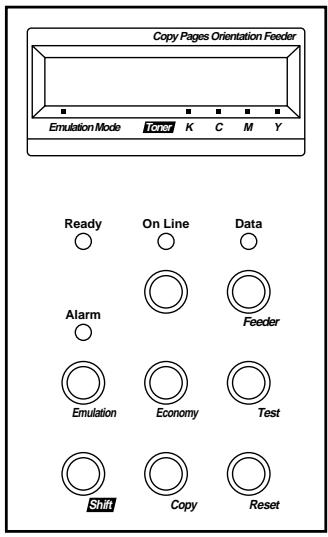
Fig. 4-8 Buttons in SHIFT Mode
Note
The factory settings are printed in bold in this section.
SHIFT Button
When you hold the Shift button down with the printer off-line, you can change settings with the panel buttons in SHIFT mode. Since the shift state is not locked, you need to hold it down and press the button to get access to the corresponding shifted function labeled under the button.
EMULATION Button
This factory setting for the automatic emulation selection function is ON. The printer will select the emulation mode automatically when it receives data from the computer.
To set the emulation mode manually, hold down the Shift button and press the Emulation button. Then enter the setting mode to change the emulation.
To set the emulation mode, follow these steps:
- Press the Sel button to take the printer off-line.
- Hold down the Shift button and press the Emulation button. When you enter the setting mode, the display first shows the current emulation mode with an asterisk.
- Press the ▲ or ▼ button until the emulation mode you want appears on the display.
| Display Message | Emulation Mode |
| AUTO | Auto Emulation Selection |
| HP PCL5C | HP PCL5C |
| BR-Script 2 | BR-Script level 2 mode |
| HP-GL | HP-GL Plotter Mode |
| EPSON FX-850 | EPSON FX-850 |
| IBM ProprinterXL | IBM Proprinter XL |
- Press the Set button to make the displayed selection effective. When you select any specific emulation mode other than "AUTO," for a short time an asterisk appears at the end of the display. Then the printer automatically exits from the setting mode to the off-line mode.
When you select “AUTO,” the sub-item “Time Out” for the automatic emulation selection appears on the display. Go to the next step.
- Set "Time Out" with the ▲ or ▼ button.
This time out is the duration during which the printer will not allow another automatic emulation change. You can set it from 1 second to 99 seconds: the factory setting is 5 seconds.
- Press the Set button.
The next sub-item “EPSON/IBM” appears on the display.
- Select EPSON or IBM with the ▲ or ▼ button.
Since the printer cannot distinguish between the EPSON and IBM emulation modes, you must select the EPSON or IBM emulation even in AUTO mode.
When the printer receives data from the computer, it automatically selects the emulation mode in any of the following combinations:
| EPSON/IBM Priority | EPSON | IBM |
| Auto Selection Mode | HP PCL5C | HP PCL5C |
| BR-Script 2 | BR-Script 2 | |
| HP-GL | HP-GL | |
| EPSON FX-850 | IBM Proprinter XL |
- Press the Set button.
The next sub-item “KEEP PCL” appears on the display.
This function is for permanent macros and fonts downloaded in the HP PCL5C mode.
- Turn on or off the "KEEP PCL" function with the ▲ or ▼ button.
When you do not need to keep the permanent macros and fonts used in HP PCL5C mode, turn this function off. When you want to keep them, you can turn it on.
If the function is turned on, the downloaded macros and fonts are kept in the printer's memory until the printer is turned off, so that they are not cleared by changing the emulation to BR-Script 2 mode.
Note
The “KEEP PCL” function reserves free space in the printer’s memory and may cause a memory full error. If a memory full error occurs, expand the memory capacity or turn off this function.
- Press the Set button.
The “exit” message appears on the display.
- Press the Set button again.
The printer exits from the setting mode to the off-line state.
Note
When you use the automatic emulation selection, try it with your application software or network server. If the function does not work properly, select a particular emulation mode manually. You can use the following commands to select the emulation on a network.
| Commands | Hex | Emulation |
| ESC CR H | 1B 0D 48 | HP PCL5C |
| ESC CR AB | 1B 0D 41 42 | BR-Script 2 |
| ESC CR GL | 1B 0D 47 4C | HP-GL |
| ESC CR E | 1B 0D 45 | EPSON FX-850 |
| ESC CR I | 1B 0D 49 | IBM Proprinter XL |
About Emulation Modes
This printer has the following emulation modes:
■ HP PCL5C Mode
This printer emulates Hewlett-Packard PCL5C color printers and PCL6 monochrome printers. This is the default emulation setting of the printer. Since many popular software packages support this emulation, this may be the best choice for general use.
■ BR-Script 2 Mode (color)
BR-Script is a Brother original page description language and it is a PostScript® language emulation interpreter. This printer has level 2 BR-Script, which supports full color printing at 600 dpi. BR-Script enables superior control for text and graphics printing. The HL2400Ce will deliver optimum performance in this mode.
Average users do not need to know much about PostScript ^® language. If you want to obtain technical information about PostScript ^® , please refer to the following commercial manuals:
- Adobe Systems Incorporated. PostScript® Language Reference Manual, 2nd Edition. Menlo Park: Addison-Wesley Publishing Company, Inc., 1990.
- Adobe Systems Incorporated. PostScript® Language Program Design. Menlo Park: Addison-Wesley Publishing Company, Inc., 1988.
- Adobe Systems Incorporated. PostScript® Language Reference Manual. Menlo Park: Addison-Wesley Publishing Company, Inc., 1985.
- Adobe Systems Incorporated. PostScript® Language Tutorial and Cookbook. Menlo Park: Addison-Wesley Publishing Company, Inc., 1985.
■ HP-GL Mode (monochrome)
The HP-GL mode is the emulation mode where this printer emulates the Hewlett-Packard plotter model HP-7475A. Since many graphics and CAD applications support this type of plotter, you can get more out of this printer working with your application software.
■ EPSON FX-850 and IBM Proprinter XL Mode (monochrome)
The EPSON FX-850 and IBM Proprinter XL emulations allow the HL-2400Ce to support the printer control language of industry-standard dot matrix printers..
ECONOMY Button
TONER SAVE MODE
You can turn on or off the toner save mode as follows:
| Display Message | Toner Save Mode |
| TONER SAVE=OFF | Turn off the toner save mode.(Factory setting) |
| TONER SAVE=ON | Turn on the toner save mode. The amount of toner on the paper decreases and the printed image may look lighter. |
POWER SAVE MODE
You can turn on or off the power save mode as follows:
| Display Message | Power Save Mode |
| POWER SAVE=ON | Turn on the power save mode. The fixing assembly of the print engine is turned off after the specified time to save power.(Factory setting) |
| POWER SAVE=OFF | Turn off the power save mode. The fixing assembly of the print engine is always powered on to keep its temperature at the specified level. |
When you turn on the power save mode with the Set button, the display shows the next sub-setting menu.
You must set the time out for the power save mode from 1 to 99 minutes with the ▲ or ▼ button: factory setting =30 minutes. The time out is the duration after which the fixing assembly of the print engine is turned off (“SLEEP”) to save power.
When the power save mode is on, the printer automatically turns on the fixing assembly again after it receives data from the computer. Since the fixing assembly must reach the specified high temperature, it takes a slightly longer time to start printing the first page.
FEEDER Button
You can select the feeder and manual feed mode with the Feeder button.
| Display Message | Feeder |
| FEEDER=AUTO | Select a feeder or auto paper feed. |
| MANUAL MODE=ON | Enable/disable the manual feed mode. |
| MEDIA TYPE | Select print media |
| SMALL SIZE | Set the small paper size detection for paper sizes under B5(JIS) |
You can check the current feeder.
When you want to change settings with the Feeder button, hold down the Shift button and press the Feeder button. You will then enter the setting mode where you change the feeder, manual feed mode, etc.
FEEDER
To select the feeder, follow these steps:
- Press the Sel button to take the printer off-line.
- Hold down the Shift button and press the Feeder button. When you enter the setting mode, the display first shows the current feeder setting with the asterisk.
- Press the ▲ or ▼ button until the feeder you want appears on the display.
| Display Message | Paper Feed Method/Paper Source |
| FEEDER=AUTO | Auto paper feed |
| FEEDER=TRAY1 | Upper Media Cassette (Tray 1) |
| FEEDER=TRAY2 | Optional Lower Media Cassette (Tray 2) |
Notes
When you select a feeder, note the following:
- The “FEEDER=TRAY2” message appears only when the optional lower tray unit has been installed.
- The FEEDER=AUTO setting allows you to optimize your printing environment. This setting allows a print job to continue uninterrupted when a paper out condition occurs. The default setting is AUTO. This setting allows a common printing situation: Loading the same size and type of paper in both paper trays allows your print job to continue without error if one of the paper trays becomes empty. The printer automatically will select the other tray when one tray becomes empty.
- When you select FEEDER=AUTO, the printer automatically searches for the paper size you set with the Mode button in the PAGE FORMAT mode and then loads the paper from the paper source that contains the selected size of paper. If the upper and lower Media Cassettes contain different sizes of paper and one Media Cassette runs out of paper, the printer stops printing without automatically changing to the other paper source to feed paper. It prevents the incorrect size of paper from being printed by mistake.
-
If you have the same size of paper loaded but of different type (i.e.: FORM “A” in Tray 1, Form “B” in Tray 2) we recommended that you change the feeder setting from AUTO to Tray 1. This will pause the printer when a paper empty condition occurs, allowing you to load the correct type of paper. Press Select to finish the print job.
-
Press the Set button to make the displayed selection effective. When you select “TRAY 1” or “TRAY 2,” for a short time an asterisk appears at the end of the display. Then the “exit” message appears on the display. Press the Set button again, so the printer exits from the setting mode to the off-line state. When you select “AUTO”, the tray selection menu for the auto paper feed appears on the display.
-
Change the tray combination and priority with the ▲ or ▼ button.
When “AUTO=T1>T2” is set, both Tray 1 and the Tray 2 are selected but tray 1 will be selected first if the paper size in tray 1 and the page size for the print job match each other. (If you are using the optional Lower Tray and want to give priority to Tray 2, you can use the “AUTO=T2>T1” setting.)
- Press the Set button.
MANUAL MODE
This printer has no manual feed tray or multi-purpose tray. Therefore you cannot feed special paper in the usual way. However this printer has a special Manual Feed Mode with Tray 1 to accommodate non-standard paper sizes. When “MANUAL MODE=ON” is selected or a manual feed command is sent to the printer, the printer will wait for you to replace the paper in Tray 1 with the paper for manual printing.
- Press the ▲ or ▼ button to select the manual mode on or off.
- Press the Set button to make the setting effective.
MEDIA TYPE
When you use anything other than ordinary plain paper (such as thick bond paper, envelope, or transparency), the appropriate media type must be selected in the media type mode to get the best print quality.
- Press the Set button to enter the media type mode. The display then shows the current setting with an asterisk.
- Press the ▲ or ▼ button to select regular, thick paper or transparency then press the Set button to make the setting effective.
Note
Please do not forget to change the setting back to regular after you have printed on your special media with the setting changed.
SMALL SIZE
This printer can detect the size of paper in the trays automatically. If there is no paper loaded as specified by the user application, the printer prompts the user to load the correct size paper by displaying “LOAD PAPER XX SIZE” on the LCD panel. The printer can detect A4, Letter, Executive, Legal (only in Optional Legal Cassette) and B5(ISO), but not A5, B5(JIS), COM10 and DL size even though they can be handled. For this reason, it is necessary to change the detection size for paper smaller than B5.
- Press the Set button to enter the small size mode. The display then shows the current setting with an asterisk. Then select "T1" or "T2".
- Press the ▲ or ▼ button to select B5 (JIS), B5 (ISO), A5, COM10 or DL then press the Set button to make the setting effective. (B5 (JIS) and B5 (ISO) only for “T2”.)
COPY Button
You can set the number of copies to print of the same page with the Copy button. The job will print faster than choosing the copy print quantity from within your application software. Check the current setting on the display.
When the number of copies has been set to 3, the display may look as follows:
LJ READY 003P T1 AUTO
Note
If you send too many pages to be stored in the printer memory, part or all of the set of pages or copies may not be printed.
To set the number of copies, follow these steps:
- Press the Sel button to take the printer off-line.
-
Hold down the Shift button and press the Copy button. When you enter the setting mode, the display first shows the current setting with the asterisk.
-
Press the ▲ or ▼ button until the desired number appears on the display.
| Display Message | # of Copies to Print Same Pages |
| COPY PAGES= 1 | 1 page |
| COPY PAGES= 2 | 2 pages |
| ... | ... |
| COPY PAGES=999 | 999 pages (max.) |
- Press the Set button to make the displayed selection effective. For a short time an asterisk appears at the end of the display. The printer then automatically exits from the setting mode to the off-line state.
RESET Button
You can reset the printer with the Reset button. The print data that the printer has already received from the computer is cleared and the printer settings are restored to the user settings or factory settings.
Any temporary download fonts and macro settings selected with commands in HP PCL5C mode are also cleared.
To reset the printer, follow these steps:
-
Press the Sel button to take the printer off-line.
-
Hold down the Shift button and press the Reset button. When you enter the reset mode, the display shows the first reset mode item.
-
Press the ▲ or ▼ button until the reset mode you want appears on the display.
| Display Message | Reset Mode |
| RESET PRINTER | Resets the printer and restores all printer settings-including command settings-to settings you have previously made. |
| RESET SETTING 1 | Resets the printer and restores all printer settings-including command settings-to the selected number (1-2) of user settings you have previously made with the Mode button. |
| RESET SETTING 2 | |
| FACTORY SETTINGS | Resets the printer and restores all printer settings-including command settings-to the factory settings.See “List of Factory Settings.” |
| RESET PARTS LIFE | This menu appears only when a maintenance part is recommended for replacement.Resets the life counter of the maintenance part that has been replaced. See Chapter 5 for detailed information. |
| Exit | Exits from the reset mode. The printer is not reset. |
- Press the Set button to make the displayed selection effective. The printer is reset according to the selected reset mode.
| Selected Mode | LCD message |
| RESET PRINTER | 08 RESET TO ↔USER SETTINGS |
| RESET SETTING 1-2 | 08 RESET TO ↔SETTING # 1* |
| FACTORY SETTINGS | 09 RESET TO ↔FACTORY SETTINGS |
1* - # indicates the selected number of saved settings
The printer automatically exits from the reset mode to the online state.
- When you enter the RESET PARTS LIFE mode:
| LCD Message | Parts replaced |
| FC ROLLER | Fuser Cleaner |
| OPC BELT | (OPC) Belt Cartridge |
| FUSER UNIT | Fixing Unit |
| 120K KIT | Drum Cleaner, Paper Discharge, Transfer Roller |
The reset item is selected according to the Maintenance message that shows the currently recommended part to replace. Press Set to reset the parts life. See Chapter 5 for more detailed information.
List of Factory Settings
The following table shows the factory settings made before shipment.
Notes
- The settings are subject to the emulation mode. Effective modes are indicated in parentheses in the following table.
- The following settings cannot be restored to the factory settings with the Reset button in the “FACTORY SETTINGS” mode: INTERFACE MODE, HRC SETTING, PAGE PROTECTION, SCALABLE FONT, LOCK PANEL, PAGE COUNTER and local LANGUAGE for display messages.
- The COPY setting is always restored to the factory setting when the printer is turned off and on again.
- The user settings are overwritten after resetting to User Settings 1 or 2.
| Button | Item | Sub-Item | Factory Setting |
| MODE | INTERFACE MODE | - | I/F=AUTO |
| For AUTO mode | |||
| TIME OUT | TIME OUT=5s | ||
| For bi-directional PARALLEL interface | |||
| HIGH SPEED | HIGH SPEED=ON | ||
| BI-DIR | BI-DIR=ON | ||
| For RS-232C serial interface | |||
| Baud Rate | BaudRate=9600 | ||
| Code Type | CodeType=8 bits | ||
| Parity | Parity =NONE | ||
| Stop Bit | Stop Bit=1 bits | ||
| Xon/Xoff | Xon/Xoff=ON | ||
| DTR (ER) | DTR (ER)=ON | ||
| Robust Xon | Robust Xon=OFF | ||
| FORMAT MODE | ORIENTATION (Except for BR-Script 2) | ORI=PORTRAIT | |
| AUTO MODE (HP PCL5C) | |||
| AUTO LF | OFF | ||
| AUTO CR | OFF | ||
| AUTO WRAP | OFF | ||
| AUTO SKIP | ON | ||
| AUTO MODE (EPSON) | |||
| AUTO LF | OFF | ||
| AUTO CR | ON (No indication) | ||
| AUTO WRAP | ON (No indication) | ||
| AUTO MASK | OFF | ||
| AUTO MODE (IBM) | |||
| AUTO LF | OFF | ||
| AUTO CR | OFF | ||
| AUTO WRAP | ON (No indication) | ||
| AUTO MASK | OFF | ||
| Button Item | Sub-Item | Factory Setting |
| MODE (continued) | ||
| FORMAT MODE (continued) | ||
| PAGE FORMAT MODE (HP PCL5C, EPSON, & IBM) | ||
| PAPER | LETTER(For 110/120V model)A4 (For 220/240V model) | |
| LEFT M | 0 (LETTER, Portrait)0 (LEGAL, Portrait)0 (A4, Portrait)0 (A5, Portrait)0 (B5, Portrait)0 (JIS B5, Portrait)0 (EXE, Portrait)0 (COM10, Portrait)0 (DL, Portrait)0 (LETTER, Landscape)0 (LEGAL, Landscape)0 (A4, Landscape)0 (A5, Landscape)0 (B5, Landscape)0 (JIS B5, Landscape)0 (EXE, Landscape)0 (COM10, Landscape)0 (DL, Landscape) | |
| RIGHT M | 80 (LETTER, Portrait)80 (LEGAL, Portrait)78 (A4, Portrait)53 (A5, Portrait)64 (B5, Portrait)67 (JIS B5, Portrait)67 (EXE, Portrait)36 (COM10, Portrait)38 (DL, Portrait)106 (LETTER, Landscape)136 (LEGAL, Landscape)113 (A4, Landscape)113 (A5, Landscape)113 (A6, Landscape)94 (B5, Landscape)97 (JIS B5, Landscape)101 (EXE, Landscape)91 (COM10, Landscape)82 (DL, Landscape) | |
| TOP M | 0.5” (HP)0.33” (Non-HP) | |
| BOTTOM M | 0.5” (HP)0.33” (Non-HP) |
| ButtonMODE(continued) | ItemPAGE FORMAT(continued) | Sub-ItemLINES (HP) | Factory Setting60 (LETTER, PORTRAIT)78 (LEGAL, PORTRAIT)64 (A4, PORTRAIT)64 (A5, PORTRAIT)53 (B5, Portrait)54 (JIS B5, Portrait)57 (EXE, Portrait)51 (COM10, Portrait)45 (DL, Portrait)45 (LETTER, LANDSCAPE)45 (LEGAL, LANDSCAPE)43 (A4, LANDSCAPE)43 (A5, LANDSCAPE)35 (B5, Landscape)36 (JIS B5, Landscape)37 (EXE, Landscape)18 (COM10, Landscape)19 (DL, Landscape) |
| LINES (Non-HP) | 62 (LETTER, PORTRAIT)80 (LEGAL, PORTRAIT)66 (A4, PORTRAIT)66 (A6, PORTRAIT)55 (B5, Portrait)56 (JIS B5, Portrait)59 (EXE, Portrait)53 (COM10, Portrait)47 (DL, Portrait)47 (LETTER, LANDSCAPE)47 (LEGAL, LANDSCAPE)45 (A4, LANDSCAPE)45 (A5, LANDSCAPE)37 (B5, Landscape)38 (JIS B5, Landscape)39 (EXE, Landscape)20 (COM10, Landscape)21 (DL, Landscape) | ||
| X OFFSET | X OFFSET=0 | ||
| Y OFFSET | Y OFFSET=0 | ||
| COLOR MODE | COLOR PRINT | COLOR PRINT=ON | |
| FORMAT MODE (BR-Script 2) | X OFFSET | X OFFSET=0 | |
| Y OFFSET | Y OFFSET=0 | ||
| FORMAT MODE (HP-GL) | PAGE FORMAT MODEPAPER | LETTER(For 110/120V model)A4 (For 220/240V model) | |
| X OFFSET | X OFFSET=0 | ||
| Y OFFSET | Y OFFSET=0 | ||
| GRAPHICS MODE (HP-GL)PEN SETTING | SIZE: 3 dotsGRAY: 100% | ||
| Button | Item | Sub-Item | Factory Setting |
| MODE (continued) | |||
| RESOLUTION MODE | RESOLUTION | RESOLUTION=600 | |
| CAPT SETTING | CAPT=OFF | ||
| HRC SETTING | HRC=MEDIUM | ||
| PAGE PROTECTION(Non-BR-Script2) | - | PROTECT=AUTO | |
| ADVANCED MODE | |||
| LOCK PANEL | LOCK PANEL=OFF | ||
| AUTO FF | AUTO FF=OFF | ||
| For AUTO FF=ON | WAIT TIME=5s | ||
| WAIT TIME | |||
| FF SUPPRESS | FF SUPPRESS=OFF | ||
| ERROR PRINT (BR-Script2) | ERROR PRINT=OFF | ||
| CONTINUE MODE | CONTINUE=MANUAL | ||
| SCALABLE FONT(HP, EPSON, & IBM) | FONT=ALL | ||
| For any interfaces | ☐☐☐☐☐ | ||
| INPUT BUFFER | |||
| PAGE COUNTER | - | 0 | |
| FONT (HP) | |||
| PRIMARY FONT | SELECT FONT | BROUGHAM | |
| SYMBOL SET | PC-8 | ||
| SECONDARY FONT | SELECT FONT | BROUGHAM | |
| SYMBOL SET | PC-8 | ||
| FONT (EPSON) | |||
| FONT | - | BROUGHAM | |
| CHARACTER SET | - | US ASCII | |
| FONT (IBM) | |||
| FONT | - | BROUGHAM | |
| CHARACTER SET | - | PC-8 | |
| EMULATION | |||
| - | - | AUTO | |
| For AUTO mode | TIME OUT | TIME OUT=5s | |
| EPSON/IBM | EPSON/IBM=EPSON | ||
| KEEP PCL | KEEP PCL=OFF | ||
| ECONOMY | - | ||
| TONER SAVE MODE | - | TONER SAVE=OFF | |
| POWER SAVE MODE | - | POWER SAVE=ON | |
| For POWER SAVE=ON | |||
| TIME OUT | TIME OUT=30m | ||
| FEEDER | |||
| FEEDER | - | FEEDER=AUTO | |
| For FEEDER=AUTO | |||
| AUTO=T1>T2 | |||
| MANUAL MODE | - | MANUAL MODE=OFF | |
| MEDIA TYPE | - | REGULAR | |
| SMALL SIZE | - | SIZE=ISO B5 | |
| COPY | - | - | COPY PAGES=1 |
| LANGUAGE (FORM FEED + POWER ON) | - | LANG=ENGLISH | |
TEST Button
You can test the printer or print the list of fonts with the Test button. To do so, hold down the Shift button and press the Test button. You will then enter the test mode where you can test the printer or print the list of fonts.
To test the printer, follow these steps:
- Press the Sel button to take the printer off-line.
- Hold down the Shift button and press the Test button. When you enter test mode, the display shows the first test mode item.
- Press the ▲ or ▼ button until the test mode you want appears on the display.
| Display Message | Test Mode |
| DEMO PAGE | Prints the demonstration page. |
| TEST PRINT | Performs the printer test and prints the test pattern. |
| PRINT CONFIG | Prints the list of control panel settings you have configured for the printer as user settings. |
| PRINT FONTS I | Prints the list of internal or resident fonts. |
| PRINT FONTS C | Prints the list of optional fonts stored in the font card. |
| PRINT FONTS P | Prints the list of permanent download fonts. |
| exit | Exits from the test mode. The printer does not perform the test. |
Note
The message “PRINT FONTS C” or “PRINT FONTS P” appears only when the optional font card is installed in the font slot or permanent download fonts are stored in printer memory.
- If the optional font card is installed, you can print the list of optional fonts. Since the list shows the ID numbers specific to each optional font, it helps you to select them with the Font button.
- If user-defined characters are already downloaded into the printer memory as permanent download fonts, you can print the list of them. For more information, see “FONT Button” in this chapter. Press the Set button to make the displayed selection effective
The printer prints the test patterns or lists according to the selected test mode.
Note
The printed list shows the panel button settings you have made as user settings with the Mode button. See “SAVE SETTINGS” in this chapter.
When the printer finishes printing, it automatically exits from the test mode to the off-line state.
This printer has a useful Hex Dump Mode for checking the print data sent from your computer. The printer lists the print data in hexadecimal form.
To enter the hex dump mode, follow these steps:
-
Check the power state.
-
Operate the buttons according to the power state.
- If the printer has been turned off, turn on the printer.
The printer starts the self-test and the display shows the following message.
04 SELF TEST
- If the printer has been turned on, reset the printer with the Reset button.
1) Press the Sel button to take the printer off-line.
2) Hold down the Shift button and press the Reset button. The display will show “RESET PRINTER”.
3) Press the Set button with the "RESET PRINTER" selected.
- Hold down the Continue / Shift button.
The printer checks the Continue / Shift button at the end of self-test or printer reset. If the button is held down, the printer enters the hex dump mode and goes on-line. The display will show the message “HEX DUMP MODE” and the printer will return to the on-line state.
Note
If the printer returns to the on-line state without displaying the message “HEX DUMP MODE”, you did not hold down the Continue / Shift button immediately after pressing the Set button. Try the above steps once again.
- Send data from your computer.
When the printer receives data, it starts printing hexadecimal values of the received data.
To exit from the hex dump mode, follow these basic steps:
-
Press the Sel button to take the printer off-line.
-
Reset the printer with the Reset button.
Or turn off the printer, wait for a few seconds, and turn it on again.
CHAPTER 5 MAINTENANCE
REPLACING THE CONSUMABLES
You will need to replace the following consumables periodically. When the time comes to replace consumables, the following messages will appear on the LCD panel.
The printer will stop printing when the following Operator Call Messages are displayed:
| LCD Operator Call Message | Consumable to Replace | Approximate Life | How to Replace | Order No. |
| 16 TONER EMPTY K COLOR | Toner Cartridge Black | 10,000 pages *1 | See 5-3 | TN-01BK |
| 16 TONER EMPTY CMY COLOR | Toner Cartridge Cyan, Magenta or Yellow | 6,000 pages *1 | See 5-3 | TN-01C TN-01M TN-01Y |
| 22 WASTE TONER | Waste Toner Pack | 12,000 images *1 *4 | See 5-11 | WT-1CL |
| 23 OIL EMPTY | Oil Bottle | 12,000 pages *1 | See 5-6 | FO-1CL |
| 24 CHANGE FCR | Fuser Cleaner | 12,000 pages *1 | See 5-9 | FO-1CL CR-1CL |
The following are Maintenance Messages that appear on the lower row of the LCD in On Line mode. These messages provide advance warning for replacing each of the consumables before they run out. To avoid any inconvenience, you may want to purchase spare consumables before the printer stops printing.
| LCD MaintenanceMessage | Consumableto Replace | ApproximateLife | How toReplace | OrderNo. |
| (Toner nearly empty)K C M Y | Toner CartridgeBlack | 10,000 pages*1 *2 | See 5-3 | TN-01BK |
| (Toner nearly empty)K C M Y | Toner CartridgeCyan, Magentaor Yellow | 6,000 pages*1 *2 | See 5-3 | TN-01CTN-01MTN-01Y |
| FUSER OIL LOW | Oil Bottle | 12,000 pages *1 | See 5-6 | FO-1CL |
The following are Maintenance Messages and appear on the lower row of the LCD in On Line mode. These messages advise you that you will need to replace each of the consumables as soon as possible, since the consumable end of life has been reached. The printer will continue printing when any of these messages are displayed:
| LCD Maintenance Message | Consumable to Replace | Approximate Life | How to Replace | Order No. | |
| REPLACE | FCR | Fuser Cleaner | 12,000 pages *1 | See 5-9 | FO-1CL CR-1CL |
| REPLACE | OPC BELT | (OPC) Belt Cartridge | 50,000 images (continuously printed) *1*4 | See 5-13 | OP-1CL |
| REPLACE | FUSER | Fusing unit | 40,000 pages *1 | See 5-17 | |
| REPLACE | 120K KIT | Drum Cleaner, Paper Discharger, Transfer Roller Paper Feeding Roller Separator Pad Transfer Drum | 120,000 pages | See 5-20 *3 | |
Note
The Ozone Filter does not have an LCD message indicator. However, you will need to replace it once a year.
*1 - at 5 % coverage print (A4-Letter size).
Note
The toner cartridges shipped with the printer contain only half the normal amount of toner. (5,000 pages (Black) and 3,000 pages (Cyan, Magenta and Yellow)).
*2 - For example, if the Cyan and Magenta toner cartridges are almost empty, the indication will be “■ □□■ ” (□ = blinking ■ ) K C M Y
If the Cyan and Magenta toner cartridges are empty, the ■ indicator will have disappeared.
*3 - To replace the Paper Feeding Roller, the Separator Pad and the Transfer Drum, consult your local dealer/retailer or Service provider.
*4 - Definition of pages: actual output page number. Definition of images: if the image on a page contains only one color of either Cyan, Magenta, Yellow or Black =>1 image, two colors =>2 images, three colors =>3 images, four colors =>4 images.
Note
- Discard the used consumables according to local regulations. If you are not sure of them, consult your local dealer/retailer. Be sure to re-seal the consumables tightly so that the material inside does not spill out. Do not discard used consumables together with domestic waste.
- We recommend placing used consumables on a piece of paper or cloth to prevent an accidental spill or scatter of the material inside.
Note
- If you use paper that is not a direct equivalent for the specified paper, consumable and part life may be reduced.
- The Projected Life for each of the items listed are based on an average of 5% coverage of the printable area using any color toner cartridge. Frequency of replacement will vary depending on the complexity of printed pages, percent coverage and media type used.
Toner Cartridges

Caution
We strongly recommend using genuine Brother toner cartridges. Using generic or refilled toner cartridges may void the warranty for this printer.
Toner Nearly Empty Message
Check printed pages, page counter, and display messages periodically. If the ■ indicator starts blinking (□), the printer has nearly run out of toner or the toner is not evenly distributed inside the cartridge.
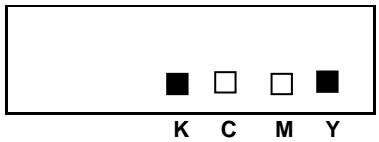
*K stands for Black, C stands for Cyan, M stands for Magenta and Y stands for Yellow.
Although you can print approximately 300 (Black) and 500 (Cyan, Magenta and Yellow) additional pages (at 5% coverage) after the toner low message first appears, be sure to replace the toner cartridge with a new one before it becomes completely empty. When this occurs, the indicator on the LCD panel will disappear.
Toner Empty Message
When the following messages appear on the LCD panel and the printer stops printing, you need to replace the Toner Cartridge(s):
16 TONER EMPTY
K COLOR
Replacing the Toner Cartridges

Caution
When replacing the Toner Cartridges, handle them carefully so that toner does not spill.

Note
To ensure optimum print quality, use genuine Brother toner cartridges. Third party toner cartridges may not work in your printer. To obtain genuine Brother supplies, consult the dealer where you purchased the printer.
To replace the toner cartridge(s), follow these steps:
- Open the Front Cover of the printer.
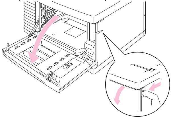
Fig. 5-1 Open the Front Cover
2 Remove the Toner Cartridge(s) which has run out of toner.
3. Take the new toner cartridge out of the box. Remove the tape labeled 'REMOVE'.
4. After rocking each new Toner Cartridge 3 to 4 times from side to side, remove the orange protective cover from the new Toner Cartridge.
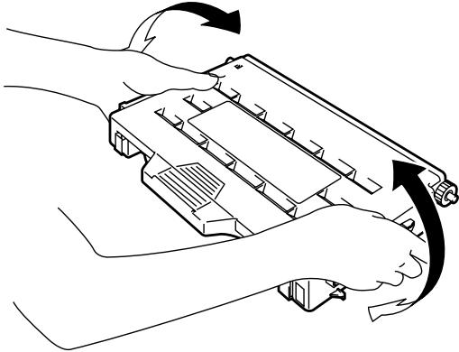
natural_image
Line drawing of a hand holding a handgun with arrows indicating motion (no text or symbols)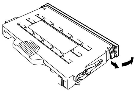
natural_image
Technical line drawing of a mechanical component with internal channels and mounting brackets (no text or symbols)Fig. 5-2 Rocking Cartridge and Removing the Protective Cover
- Insert the new Toner Cartridge(s) by positioning it in the correct guide(s). Slide it gently into the printer. Do not try to lock or push them in; they must rest loosely in the guide rails. Note that each color cartridge is individually keyed to prevent improper installation. Match each cartridge color label to the corresponding label on the printer.
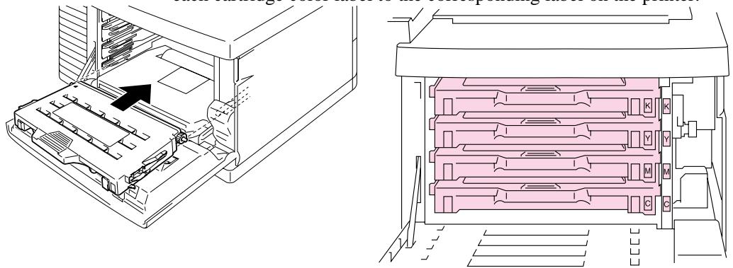
natural_image
Technical line drawing of a computer tower with internal components and storage racks (no text or symbols)Fig. 5-3 Installing the Toner Cartridges
- Close the Front Cover.

Caution
- Insert the toner cartridges gently into the printer. Do not try to lock them into the printer by pushing them, they must stay loosely in the guide rails, they will be correctly positioned when the front cover is closed.
- The printer may be damaged or may not work correctly if you install consumables other than genuine Brother supplies or if you use refilled toner cartridges. This could void your warranty.
- Do not stand the toner cartridge on its end or turn it upside down.
- Install the toner cartridges immediately after you remove the protective cover. Do not touch the shaded area shown below: .

natural_image
Illustration of hands holding a device with a pink X-shaped overlay (no text or symbols)Fig. 5-4 Toner Cartridges
Oil Bottle
Oil Bottle Low Message
When the Oil has almost run out, the following message appears on the LCD panel. Prepare a new Oil Bottle to replace the nearly empty bottle. After this message appears, you can print approximately 30 pages:
FUSER OIL LOW
Oil Bottle Empty Message
When the Oil completely runs out, the following message appears on the LCD panel and the printer stops printing. When you see this message, you must replace the Oil Bottle with a new one:
23 OIL EMPTY

Warning
The Fusing Unit and the parts around it are HOT! Be sure to wait until the Fusing Unit has cooled sufficiently before replacing the Oil Bottle.
If you touch the HOT parts, you might get injured.

Caution
Be careful not to spill oil inside the printer, it may cause considerable damage and void your warranty. If you spill some oil, consult your dealer or Brother authorized service representative.
Replacing the Oil Bottle
- Press the Power button to turn off the printer and wait until it has cooled down sufficiently.
-
Open the Top Cover.
-
Release the Oil Bottle Lock Levers as shown below:

natural_image
Technical line drawing of a mechanical assembly with no visible text or symbolsFig. 5-5 Release the Oil Bottle Lock Levers
- Remove the empty Oil Bottle from the Fusing Unit. Hold a sheet of paper under the Oil Bottle and lift it out of the Fusing Unit. Move the bottle toward the right hand side of the printer, so that the oil will not spill into it.. Be careful not to spill oil inside the printer. It could cause considerable damage to the printer.
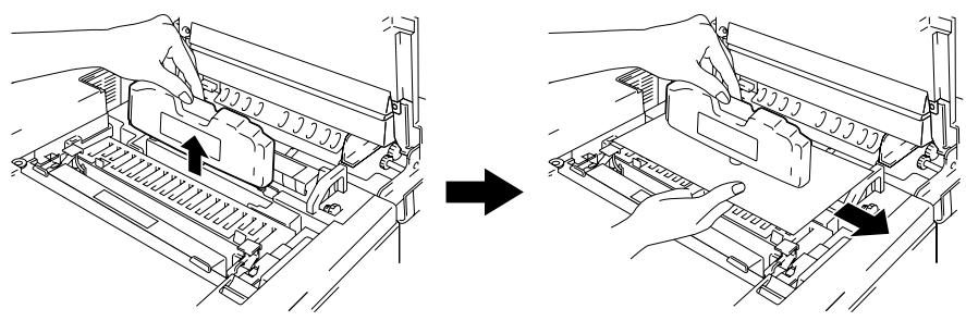
natural_image
Diagram showing two steps of a printer or printer assembly process, with no visible text or symbols.Fig. 5-6 Take the Oil Bottle out
- Install the new Oil Bottle into the Fusing Unit with the label facing the front of the printer. This will enable the Oil Bottle to fit into the cutout in the top of the Fusing Unit.
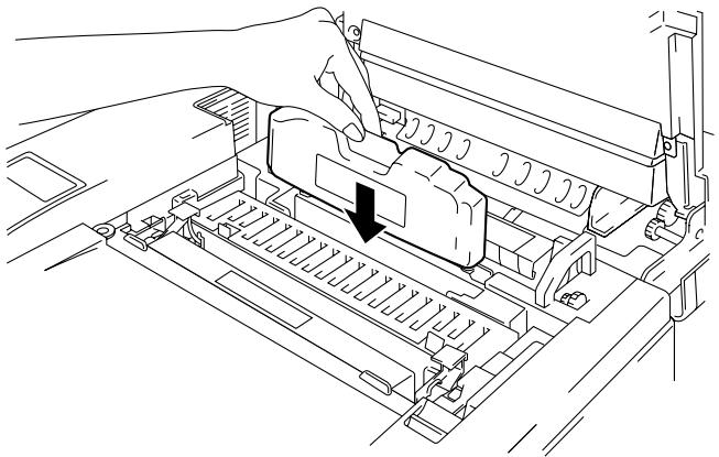
natural_image
Technical line drawing of a printer internal structure with no visible text or symbolsFig. 5-7 Install the Oil Bottle
- Lock the Oil Bottle Lock Levers securely.
- Close the Top Cover.
- Press the Power button to turn the printer On.
Fuser Cleaner
Fuser Cleaner Message
When the following message appears on the LCD panel, you will need a replacement Fuser Cleaner:
REPLACE FCR
Fuser Cleaner Change Message
When the following message appears on the LCD panel and the printer stops printing, you must replace the Fuser Cleaner:
24 CHANGE FCR
Replacing the Fuser Cleaner

Warning
The Fusing unit and the parts around it are HOT! Be sure to wait until the Fusing Unit has cooled sufficiently before replacing the Fuser Cleaner.
If you touch the HOT parts, you might get injured.
- Press the Power button to turn the printer off and wait until it has cooled down sufficiently.
- Open the Top Cover.
- Release the Oil Bottle Lock Levers on both sides as shown below:
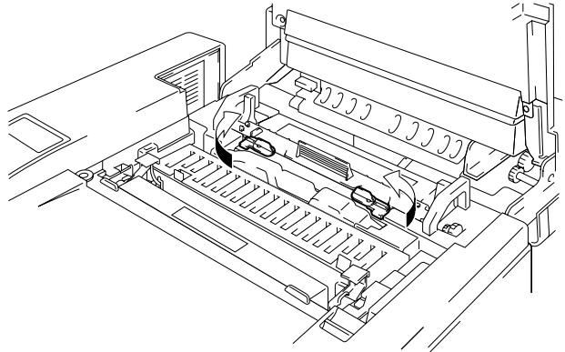
natural_image
Technical line drawing of a printer internal structure (no text or symbols)Fig. 5-8 Release the Levers
- Take the Fuser Cleaner out of the Fusing Unit by holding the handle of the Fuser Cleaner as shown below:
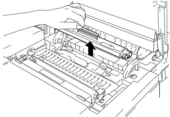
natural_image
Line drawing of a printer's internal structure showing a hand inserting a slot into a rack (no text or symbols)Fig. 5-9 Removing the Fuser Cleaner
- Install the new Fuser Cleaner into the guide with the roller side facing you.
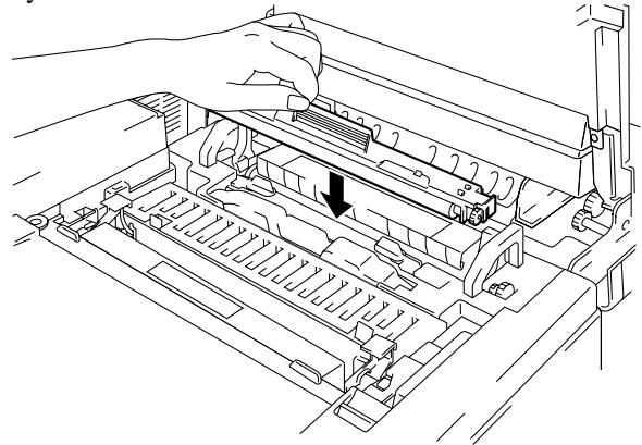
natural_image
Line drawing of a printer's internal structure with a hand adjusting the tray (no text or symbols)Fig. 5-10 Installing the Fuser Cleaner
- Lock the Fuser Cleaner with the Oil Bottle Lock Levers.
- Close the Top Cover.
- Press the Power button and turn the printer On.
- Press the Sel button and take the printer Off Line.
- Press the Reset button while holding down the Shift button.
- When you see “RESET PRINTER” on the LCD panel, press the ▲ (UP) or ▼ (DOWN) button and select “RESET PARTS LIFE”. Press the Set button and select “FC ROLLER” with the ▲ (UP) or ▼ (DOWN) button.
- Press the Set button, the printer is now On Line.
Waste Toner Pack
Approximately every 12,000 images you print at 5% coverage, you must change the Waste Toner Pack.
Waste Toner Pack Full Message
When the West Toner Pack is full, the following message appears on the LCD panel and the printer will stop printing. When you see this message, you must replace the Waste Toner Pack:
22 WASTE TONER

Caution
Do not re-use the Waste Toner Pack.
Replacing the Waste Toner Pack

Warning
- Do not put the Waste Toner Pack into a fire. It could explode.
- Be careful not to spill the toner. Do not inhale or allow it to get into your eyes.

Caution
Be careful when you handle the Waste Toner Pack so that toner will not spill on your hands or clothes.
- Open the Front Cover.
- Remove the Waste Toner Pack from the holder located at the lower right side of the printer. Be careful not to spill the toner.
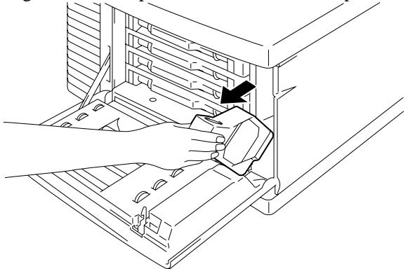
natural_image
Line drawing of a hand inserting a device into a rack, showing internal components and a black arrow indicating the component (no text or symbols present)Fig. 5-11 Take the Waste Toner Pack out
- Peel off the sealing sticker on the left side of the Waste Toner Pack. Seal the opening with the sealing sticker. See Fig. 5-12 for the correct placement of the sticker.
When you dispose of the used Waste Toner Pack, place it in the plastic bag included with the replacement Waste Toner Pack. Please dispose of the Waste Toner Pack in accordance with local regulations.
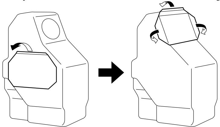
natural_image
Diagram showing a mechanical component before and after rotation, with no text or symbols present.Fig. 5-12 Seal the Sealing Sticker
- Insert the new Waste Toner Pack into the Waste Toner Pack Holder.
- Close the Front Cover.
OPC Belt Cartridge
OPC Belt Cartridge Message
When the OPC Belt Cartridge runs out, the following message appears on the LCD panel. When you see this message, you must replace the OPC Belt Cartridge:
REPLACE OPC BELT

Caution
- Do not touch the surface of the OPC Belt Cartridge. If you touch it, it could degrade print quality.
- Do not expose the OPC Belt Cartridge to light (more than 800 lux) for more than 2 minutes. This could degrade print quality. Be sure to open the printer Front Cover BEFORE you open the Top Cover to handle the OPC Belt Cartridge.
- Damage caused by improper handling of the OPC Belt Cartridge may void your warranty.
Replacing the OPC Belt Cartridge
- Press the Power button and turn the printer Off.
- Open the Front Cover and then open the Top cover.
- Pull the green Belt Cartridge Lock Levers on both sides toward you to release the lock.
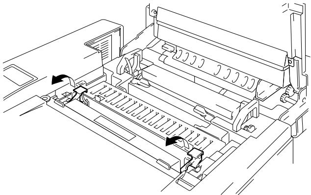
natural_image
Technical line drawing of a printer internal structure with no visible text or symbolsFig. 5-13 Releasing the Belt Cartridge Lock Levers
- Remove the OPC Belt Cartridge from the printer.
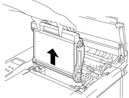
natural_image
Line drawing of a printer's internal structure with an upward arrow indicating motion (no text or symbols present)Fig. 5-14 Removing the OPC Belt Cartridge
- Remove the Tension Release Pins from both sides of the new OPC Belt Cartridge.
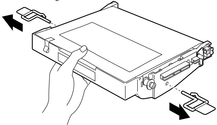
natural_image
Line drawing of a computer case with hands holding a tray, showing internal components and directional arrows (no text or symbols)Fig. 5-15 Removing the Tension Release Pins
- Remove the protective sheet from the new OPC Belt Cartridge. Do not touch the green part of the OPC Belt Cartridge.
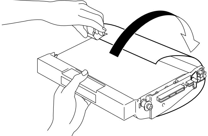
natural_image
Line drawing of hands operating a device with a curved arrow indicating motion (no text or symbols)Fig. 5-16 Removing the Protective Sheet
- Insert the new Belt Cartridge into the printer guides with the flat side facing you.
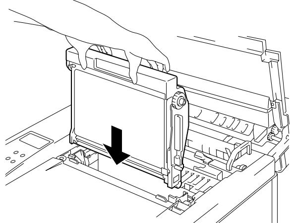
natural_image
Technical line drawing of a mechanical assembly with a black arrow indicating a downward motion (no text or symbols present)Fig. 5-17 Inserting the new Belt Cartridge
- Press the Belt Cartridge Lock Levers on both sides of the OPC Belt Cartridge to the rear to lock the cartridge into the printer.
- Close the Front Cover and the Top Cover.
- Press the Power button and turn the printer On.
- Press the Sel button and take the printer Off Line.
- Press the Reset button while holding down the Shift button.
- When you see “RESET PRINTER” on the LCD panel, press the ▲ (UP) or ▼ (DOWN) button and select “RESET PARTS LIFE”. Press the Set button and select “OPC BELT” with the ▲ (UP) or ▼ (DOWN) button.
- Press the Set button, the printer is now On Line.
Ozone Filter
Ozone Filter
You will need to replace the Ozone Filter once a year to prevent ozone from coming out of the printer.

Caution
You must replace the Ozone Filter once a year. If you do not, it might cause a noticeable smell of Ozone.
Replacing the Ozone Filter
- Slide and remove the Rear Side Cover.
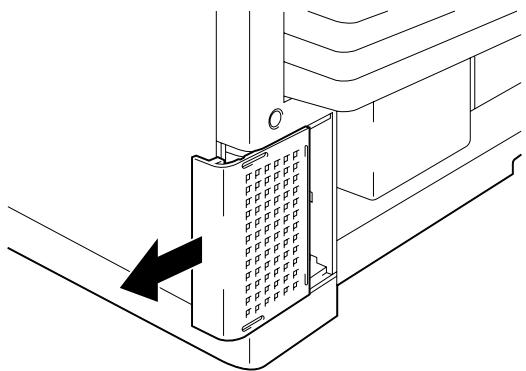
natural_image
Technical diagram of a mechanical assembly with a grid-patterned component and directional arrow (no text or symbols)Fig. 5-18 Removing the Ozone Filter Case
- Remove the Ozone Filter Case from the Ozone Filter Cover.
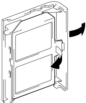
natural_image
Technical line drawing of a door frame with internal compartments and directional arrows indicating movement (no text or symbols)Fig. 5-19 Removing the Ozone Filter
- Insert the new Ozone Filter Case into the Ozone Filter Cover.
- Reinstall the Rear Side Cover by sliding it into place.
Fusing Unit
Fusing Unit
When the following message appears on the LCD panel, you must replace the Fusing Unit:
REPLACE FUSER

Warning
The Fusing Unit and the parts around it are HOT!. Be sure to wait until the Fusing Unit has cooled down sufficiently before replacing the Fusing Unit.
If you touch the HOT parts, you might get injured.

Warning
After replacing the Fusing Unit, wait for approximately 30 minutes before printing after the new unit is installed to allow the fusing oil to circulate.
Replacing the Fusing Unit
- Press the Power button and turn off the printer. Unplug the printer. To avoid injury wait until the printer has cooled down sufficiently before replacing the Fusing Unit.
- Open the Top Cover and the Rear Access Cover.
- Remove the screws as shown below (Fig. 5-20) inside the Rear Access Cover and release the metal retaining clips.
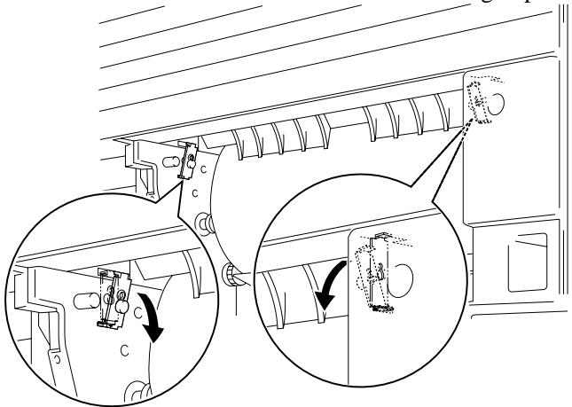
Fig. 5-20 Remove and release the Metal retaining clips
Note
If you begin using a new Fusing Unit immediately, poor print quality may result. Please wait for 30 minutes after installing a new Fusing Unit to allow the oil to circulate completely through to the Heat Roller.
- Remove the Fusing Unit from the printer by holding the handles on both sides.
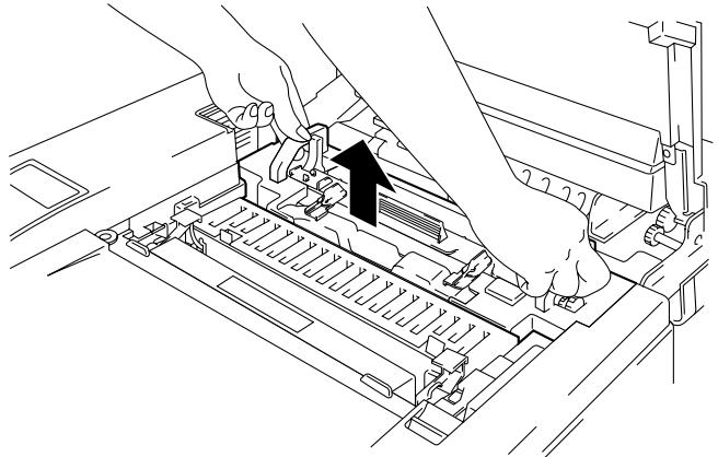
natural_image
Line drawing of hands operating a mechanical device with a black arrow indicating the component (no text or symbols present)Fig. 5-21 Removing the Fusing Unit

Caution
When removing the Fusing Unit from the printer, be sure to keep the Fusing Unit flat, so oil will not spill. Considerable damage can occur if oil is spilled inside the printer.
- Remove the Oil Bottle and the Fuser Cleaner from the Fusing Unit.
- Install the new Fusing Unit into the printer. Be sure to insert the Fusing Unit completely into the printer.
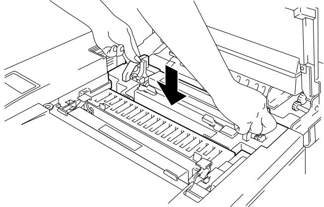
natural_image
Line drawing of hands operating a mechanical device with a black arrow indicating a component (no text or symbols present)Fig. 5-22 Installing the New Fusing Unit
- Place the retaining clips into the holes in the Fusing Unit and secure them with the two screws.
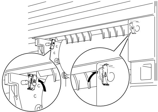
natural_image
Technical line drawing of a mechanical assembly with two views (top and side), no text or symbols present.Fig. 5-23 Secure the retaining clips
- Release the Fusing unit by pushing the Pressure Release Levers to the OPEN position (①). Remove the orange protective parts fitted between the rollers of the Fusing Unit (②). Make sure that the Pressure Release Levers are put back to the SET position.
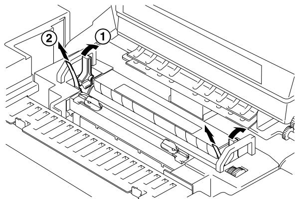
Fig. 5-24 Removing the Protective Parts
- Install the Fuser Cleaner and the Oil Bottle into the new Fusing Unit and Lock the Oil Bottle Lock Levers. Be careful not to spill oil inside the printer. This could damage the printer.
- Close the Top Cover.
- Plug the printer into the AC outlet.
Note
If the condition of the Fuser Cleaner is poor, we recommend that you replace the Fuser Cleaner at the same time as the Fusing Unit. The life counter for the Fuser Cleaner will also need to be reset. Please refer to page 5-10 for instructions.
Partially used Oil Bottles can be reused with a new Fusing Unit.
Please wait for 30 minutes after installing a new Fusing Unit to allow the oil to circulate completely through the Heat Roller.
- Press the Power button and turn on the printer.
- Press the Sel button and take the printer Off Line.
- Press the Reset button while holding down the Shift button.
- When you see “RESET PRINTER” on the LCD panel, press the ▲ (UP) or ▼ (DOWN) button and select “RESET PARTS LIFE”. Press the Set button and select “FUSER UNIT” with the ▲ (UP) or ▼ (DOWN) button.
- Press the Set button, the printer is now On Line.

Caution
Please be careful when replacing the Fusing Unit. Do not place pressure on the Fusing Unit; it should fit in easily. If it does not, make sure the Fusing Unit connector is free to move.
Do not apply force! It could damage both the Fusing Unit and the printer.
120K Kit
120K Kit
When you see the following message on the LCD panel, you must replace the items located in the 120K Kit, which includes the Drum Cleaner, Paper Discharger, Transfer Roller, Paper Feeding Roller, Separator Pad and the Transfer Drum.
Note
- User replacement of some of the following 120K Kit parts is not recommended.
- For user replacement of the Drum Cleaner, Paper Discharger and Transfer Roller, please refer to the instructions found below.
- We recommend that you contact your local Brother authorized dealer or service center for replacing the Paper Feeding Roller, Separator Pad and Transfer Drum.
- We recommend you contact your Service provider when you see the following message on the LCD panel:
REPLACE 120K KIT
Drum Cleaner

Caution
Both ends of the Drum Cleaner roller consist of metal bearings that connect the bias element to the power supply. These must be connected correctly when you install the Drum Cleaner. Be sure to check how to connect these properly by referring to the old Drum Cleaner before you begin replacement.
Replacing the Drum Cleaner
- Press the Power button and turn the printer Off.
- Open the Top Cover.
- Remove the Drum Cleaner Cover.
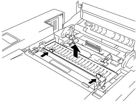
natural_image
Technical line drawing of a printer internal structure with no visible text or symbolsFig. 5-25 Opening the Cover
- Remove the Drum Cleaner by gently pushing the handle away from you until it releases and then lift it out of the printer.

natural_image
Technical line drawing of a vehicle chassis with internal components and a black arrow indicating a specific component (no text or symbols present)Fig. 5-26 Removing the Drum Cleaner
- Install the new Drum Cleaner into the printer by gently placing the brass bearings into the guides and pushing the handle down until the bearings click into place. Ensure that the Drum Cleaner is free to move slightly upwards (rotating slightly around the bearings) in the housing after you have installed it.
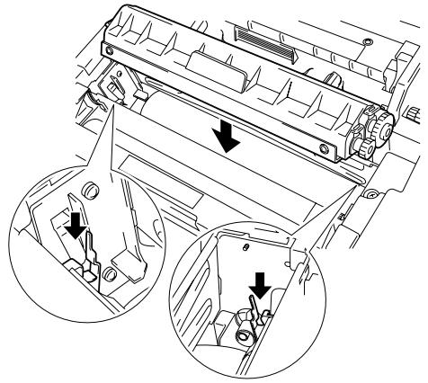
natural_image
Technical diagram of a vehicle engine compartment showing internal components and directional arrows (no text or labels)Fig. 5-27 Installing the New Drum Cleaner
- Re-install the Drum Cleaner Cover and close the Top Cover.
Paper Discharger

Caution
Do NOT touch the charging wire!
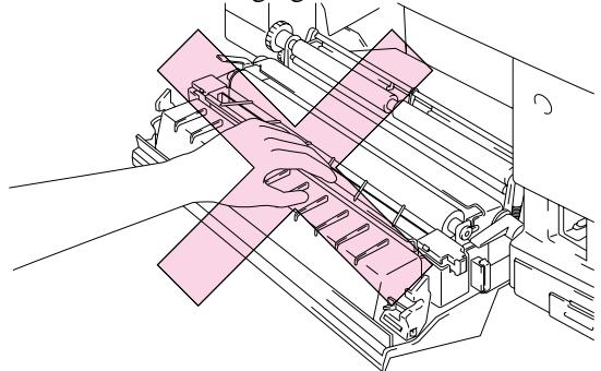
natural_image
Technical line drawing of a mechanical assembly with hands operating a component (no text or symbols visible)Fig. 5-28 Charging Wire
Replacing the Paper Discharger
- Open the Rear Access Cover.
- Remove the Paper Discharger from the Transfer Unit by lightly pressing it down and then sliding it to the right to release it from the catches. Hold the right hand side of the Discharging Unit and lift it upward to remove it.
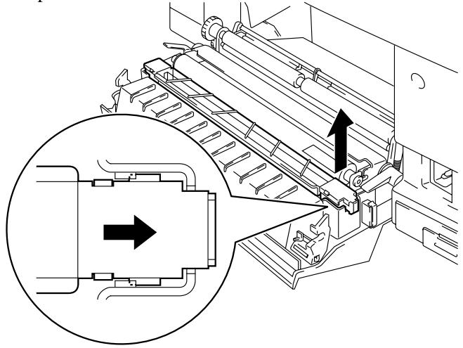
natural_image
Technical line drawing of a mechanical device with an inset showing internal components (no text or symbols)Fig. 5-29 Removing the Paper Discharger
- Install the new Paper Discharger into the Transfer Unit in the reverse order that you removed it.
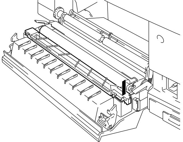
natural_image
Technical line drawing of a mechanical assembly with rollers and mounting brackets (no text or symbols)Fig. 5-30 Installing the Paper Discharger
Replacing the Transfer Roller
- Release the green Transfer Roller Lock Lever and lift the Lever to release the Transfer Roller.
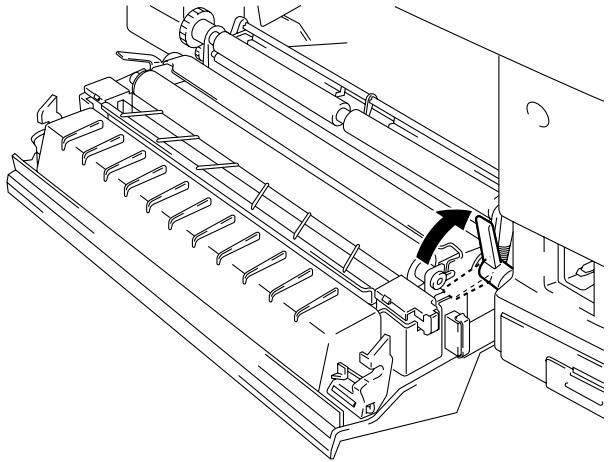
natural_image
Technical line drawing of a mechanical assembly with no visible text or symbolsFig. 5-31 Releasing the Lock Lever
- Remove the Transfer Roller by gently pulling the right hand side upwards. Slide the Transfer roller to the right to remove it.
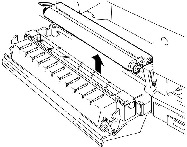
natural_image
Technical line drawing of a mechanical assembly with rollers and a directional arrow (no text or symbols)Fig. 5-32 Taking out the Transfer Roller
- Install the new Transfer Roller by inserting the left side opening of the Transfer Roller into the pin on the left rear side of the unit. Adjust the position of the Lock lever to allow the right side of the Transfer Roller to slip into the holder.
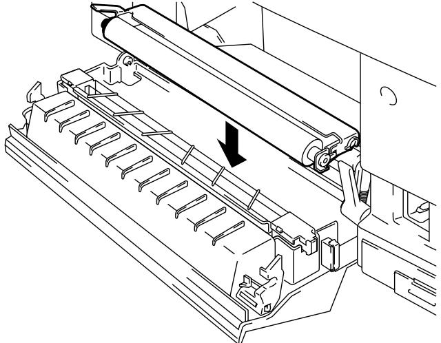
natural_image
Technical line drawing of a mechanical assembly with a roller roller and mounting bracket (no text or symbols)Fig. 5-33 Installing the Transfer Roller
- Lock the Transfer Roller with the Transfer Roller Lock Lever.
- Close the Rear Access Cover.
- Plug the power cord into the power outlet and press the Power button to turn on the printer.
Note
- User replacement of some of these parts by is not recommended.
- For replacement of the Paper Feeding Roller, Separator Pad and the Transfer Drum, consult your local dealer/retailer.
- Actions 7 to 10 should only be carried out by your dealer or Brother authorized service center when they have replaced the Paper Feeding Roller, Separator Pad and the Transfer Drum.
-
Replacement of only the Paper Discharger and the Transfer Roller is not a full 120K service and the counter should not be reset until these additional parts are replaced.
-
Press the Sel button and take the printer Off Line.
- Press the Reset button while holding down the Shift button.
- When you see “RESET PRINTER” on the LCD panel, press the ▲ (UP) or ▼ (DOWN) button and select “RESET PARTS LIFE”. Press the Set button and select “120K KIT” with the ▲ (UP) or ▼ (DOWN) button.
- Press the Set button, the printer is now On Line.
Clean the printer exterior and interior periodically with a dry soft cloth. If the printed page gets stained with toner, clean the printer interior with a dry soft cloth.
Cleaning the Printer Exterior
Clean the printer exterior as follows:
- Turn off the printer and unplug the power cord.
- Remove the Media Cassette from the printer.
- Wipe the printer body with a soft cloth to remove dust.
Dip the cloth in water and wring it out thoroughly for cleaning.
Note
Use water for cleaning. Cleaning with volatile liquids such as thinner or benzine will damage the surface of the printer.
Do not use cleaning materials that contain ammonia. They could damage the printer, particularly the toner cartridges.
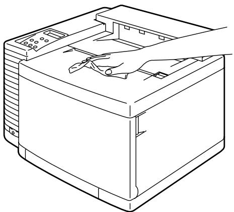
natural_image
Line drawing of a computer with a hand operating the top panel (no text or symbols)Fig. 5-34 Cleaning the Printer Exterior
Periodic Printer Cleaning
Every 20,000 pages printed or every 12 months, we recommend cleaning the following parts with a dry cloth.
Clean the Paper Guide and Registration Roller to prevent paper jams.

natural_image
Technical line drawing showing two views of a mechanical device with hands operating the internal components (no text or symbols present)Fig. 5-35 Paper Guide and Registration Roller
Clean the Exit Roller after opening the Top Cover slightly. This will help to prevent paper jams at the paper exit or dirt from appearing on your print output.
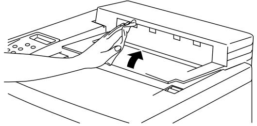
natural_image
Line drawing of a hand inserting a component into a device casing (no text or symbols)Fig. 5-36 Top cover and Exit Roller
Caution
- Whenever you transport the printer ALWAYS use the packing materials that were provided with your printer. Follow the steps detailed below to re-pack the printer or the printer may be damaged. This will void the printer's warranty.
- Before you ship or move the printer, be sure to take out the following items and put them in separate bags (do not put them in the printer carton box):
* Fusing Unit
* Waste Toner Pack
* Toner Cartridges
* OPC Belt Cartridge
- Remove the Oil Bottle and then use the syringe supplied with the printer to remove Oil from the Fusing Unit tray. . Using a cloth, wipe up any remaining oil that cannot be removed with the syringe.
- Discard the oil according to local regulations.
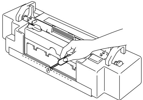
natural_image
Technical line drawing of a mechanical assembly with a hand operating a tool (no text or symbols present)Fig. 5-37 Removing the Oil
How to Repack the Printer
- Press the Power button and turn the printer off. Unplug the printer.
- Remove the Waste Toner Pack, the Toner Cartridges, the Fusing Unit and the OPC Belt Cartridge from the printer. Place them in their original packaging. Do not place them together with the printer in the printer carton.
- Place the printer in its original packing material and in the original carton.
- Close the carton and tape it securely.
Lower Tray Unit
Loading Paper from the Lower Media Cassette
The lower tray unit is a device that functions as a second paper source. It can hold a maximum of 250 sheets of paper (160 g/m ^2 or 43 lbs). To purchase the optional lower tray unit, please consult the dealer where you purchased the printer.
With the lower tray unit installed, load paper into the lower paper cassette in the same way as you do the upper media cassette.
How to Install the Lower Tray Unit

Warning
- This printer is heavy and weighs approximately 37kg (81.6 lbs). When moving or lifting this printer, be sure to do so with at least 2 people to avoid injury.
- Be sure to lift the printer using the handholds located at the bottom four corners of the printer.

Caution
When moving or lifting this printer, be sure to keep the printer flat. Also, you must first remove the Toner Cartridges, Waste Toner Pack, Oil Bottle and Fusing Unit to avoid spills.
- Place the Lower Tray Unit on a flat table.
- Remove both side covers from the Lower Tray Unit.
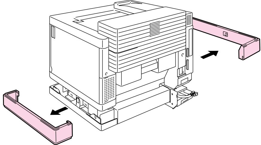
natural_image
Technical line drawing of a mechanical device with labeled components and directional arrows indicating assembly (no text or symbols present)Fig. 5-38 Remove the Covers
- Pull out the connection cable located at the left rear side of the Lower Tray Unit.
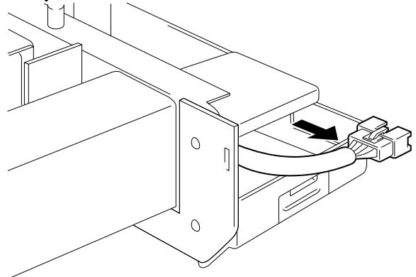
natural_image
Technical line drawing of a mechanical assembly with a curved pipe or connector (no text or symbols)Fig. 5-39 Pulling out the Connection Cable
- Check the three alignment pins on the Lower Tray Unit. Use two people to lift the printer and place it onto the Lower Tray Unit. Be sure to use the handholds located at the bottom four corners of the printer. Check to ensure that the pins align correctly into the printer.
natural_image
Technical line drawing of a mechanical device with base and top views, showing internal components and a downward arrow indicating motion (no text or symbols present)Fig. 5-40 Place the Printer on the Lower Tray Unit
- Insert the Metal Clips into both sides of the Lower Tray Unit and secure with screws.
natural_image
Line drawing of a traditional-style building with two circular insets showing interior details (no text or symbols)Fig. 5-41 Inserting the Metal Clips and Securing with Screws
- Remove the Connector Cover of the printer.
natural_image
Technical line drawing of a mechanical assembly with no visible text or symbolsFig. 5-42 Remove the Cover
- Insert the connection cable into the printer's connector.
natural_image
Technical line drawing of a mechanical assembly with no visible text or symbolsFig. 5-43 Inserting the Connection Cable
- Remove the Connector Cover of the Lower Tray Unit and fit it to the printer so that it covers the connector part. Fit the Connector Cover of the printer to the Lower Tray Unit.
natural_image
Technical line drawing of mechanical assembly with two views (no text or symbols)Fig. 5-44 Fit the Covers
- Install the covers on both sides of the Lower Tray Unit.
natural_image
Technical line drawing of a mechanical device with mounting bracket and directional arrows indicating assembly or movement (no text or symbols)Fig. 5-45 Installing the Cover

Note
Do not load B5 or smaller size paper and envelopes in the cassette loaded into the optional Lower Tray Unit. It may cause paper jams.
Font Card, Flash Memory/HDD Card
Installing a Font Card, Flash Memory Card and HDD Card
This printer has two slots for an optional font cartridge and one slot for an optional font card, flash memory card or HDD card. (Type III HDD cards will only fit into card slot 2.)
If you have installed optional font card(s), you can use the fonts stored in them as well as the resident fonts. For optional font cards, consult the dealer where you purchased the printer.
If you have installed an optional flash memory card or HDD card, you can save macros and fonts on it. For flash memory card and HDD card operations and information, see “DEVICE OPERATION” in Chapter 4.
Notes
- Do not install or remove cards with the power on, or you may lose all data and may seriously damage the card.
- For more information about these cards, consult the dealer where you purchased the printer.
• For the latest information: http://www.brother.com
Follow these steps to install or remove a cartridge/card:
- Make sure the printer is turned off.
If the printer is turned on, be sure to press the Sel button to take the printer off-line. If data remains in the printer memory, the Data LED stays on. Press the Form Feed button to print out the remaining data, then the Data LED goes off. Turn off the printer.
- Insert an HDD card into slot 2 with the label facing to the right. It is not possible to fit a card into slot 1 with a Type III PCMCIA card fitted in slot 2.
- Fit a flash memory or font card into either slot 1 or slot 2 with the label facing to the right. Make sure they are inserted correctly.
To remove a card, pull it out of the slot with the printer turned off.
The following type of flash memory card can be installed:
• 4 Mbyte : Fujitsu MB98A81273
• 8 Mbyte : Fujitsu MB98A81373
• 16 Mbyte : Fujitsu MB98A81473
• 32 Mbyte : Fujitsu MB98A81573
• 1 Mbyte : AMD AMC001CFLKA
- 2 Mbyte : AMD AMC002CFLKA
• 4 Mbyte : AMD AMC004CFLKA
• 10 Mbyte : AMD AMC010CFLKA
• 4 Mbyte : AMD AMC004DFLKA
- 8 Mbyte : AMD AMC008DFLKA
- 20 Mbyte : AMD AMC020DFLKA
• 2-85 Mbyte : SanDisk PCMCIA PC Card ATA
natural_image
Technical line drawing of two mechanical assembly components with no visible text or symbolsFig. 5-46 Installing or Removing the Card
Selecting the Optional Fonts
After you have installed the optional font card, you can select optional fonts by any of the following methods:
- Through your application software
- With a font selection command
- With the Font button
When you select fonts through your application software, follow the instructions specific to your software. Refer to your software manual if you need assistance. When you select fonts with a font selection command, embed the font selection command in your program. See the Technical Reference Manual, which is optionally available for this printer.
Notes
When you select the fonts through your software or with a command, note the following:
- You do not need to be concerned about the Font button setting. The software or command setting overrides the button setting.
- Be sure to install the font card that has your desired fonts. The printer automatically selects the font that has exactly the same or similar characteristics as those you set through the software or with a command. If the installed font card happens to have a font of similar characteristics, the printer will print in an unexpected font.
To select fonts with the Font button, follow these basic steps:
-
Print the list of optional fonts in the PRINT FONTS C mode with the Shift and Test buttons.
-
Find the font slot and font ID number on the list.
Font ID Number
| PORTRAIT LIST | ||||||
| NUMBER | SYMBOL | SET | SLOTFONT B | |||
| (D) | FITCH | SIZE | STYLE | WEIGHT | TYPESANCE | F O N T S A H P L E(600dpi) |
| B000 | BU:ROXAN 8... | |||||
| Pr31.42 | 11.00 | Ipright (D) | Medium (D) | Time Roman (5) | ABCDefgh123?!"#%&' ()<>/012345 | |
| ESC(CUESC(slp#0=0)bST) | ||||||
| B001 | DN; | |||||
| Pr31.42 | 11.00 | Ipright (D) | Medium (D) | Time Roman (5) | ABCDefgh123?!"#%&' ()<>/012345 | |
| ESC(CUESC(slp#0=0)bST) | ||||||
| B002 | 10:PC-8... | |||||
| Pr31.42 | 11.00 | Ipright (D) | Midism (D) | Time Roman (5) | ABCDefgh123?!"#%&' ()<>/012345 | |
| ESC(CUESC(slp#0=0)bST) | ||||||
| B003 | 110:PC-8 D/N... | |||||
| Pr31.42 | 11.00 | Ipright (D) | Medium (D) | Time Roman (5) | ABCDefgh123?!"#%&' ()<>/012345 | |
| ESC(CUESC(slp#0=0)bST) | ||||||
| B004 | 120:PC-85D... | |||||
| Pr31.42 | 11.00 | Ipright (D) | Medium (D) | Time Roman (5) | ABCDefgh123?!"#%&' ()<>/012345 | |
| ESC(CUESC(slp#0=0)bST) | ||||||
| B005 | 70; | |||||
| Pr31.42 | 11.00 | Ipright (D) | Medium (D) | Time Roman (5) | ABCDefgh123?!"#%&' ()<>/012345 | |
| ESC(CUESC(slp#0=0)bST) | ||||||
| B006 | BU:ROXAN 8... | |||||
| Pr31.42 | 11.00 | Ipright (D) | Bold (3) | Time Roman (5) | ABCDefgh123?!"#$%&' ()<>/01234 | |
| ESC(CUESC(slp#0=0)bST) | ||||||
Fig. 5-47 Font ID Numbers on the Font List
- Select the font with the Font button.
See “FONT button” in Chapter 4.
Network Option
NC-3100h
Some models of this printer may include an NC-3100h network card as standard.
Installing NC-3100h enables you to use the printer in the following environments:
(TCP/IP, IPX/SPX, AppleTalk, DLC/LLC, VINES, LAT, NetBEUI) Also, many useful utilities such as the BR-Admin and the Brother Network Printing software for the administrator are included. For the details of the utilities, see the documentation included on the CD-ROM.
- Turn off the printer and unplug the power cord from the AC outlet.
- Unscrew the two screws securing the rear plate of the main controller board. Remove the screws and pull out the main controller board.
natural_image
Technical line drawing of a mechanical assembly with no visible text or symbolsFig. 5-48 Unscrew the two screws
- Unscrew the two screws and remove the MIO cover plate.
-
Take the NC-3100h Card out of the box.
-
Insert the NC-3100h connector into the connector between the guide rails and secure with the two screws.
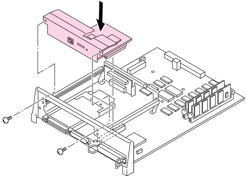
natural_image
Isometric technical diagram of an electronic device chassis with labeled components and a pink component (no text or symbols present)Fig. 5-49 Installing the NC-3100h Controller
- Secure the NC-3100h with the Lock Bar.

natural_image
Technical line drawing of a computer chassis with internal components and a connector (no text or symbols)Fig. 5-50 Securing the NC-3100h with the Lock Bar
- Re-install the main controller board into the printer by sliding it into the guide rails.
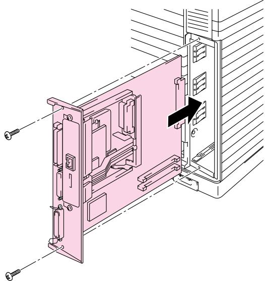
natural_image
Technical line drawing of a mechanical assembly with no visible text or symbolsFig. 5-51 Installing the Main Controller Board
- Secure the main controller board with the two screws.
- Connect the network cable to the NC-3100h Card.
- Connect the AC power cord and turn on the printer.
- For more details on how to optimize the NC-3100h, please refer to the Network User's Guide supplied with this printer.
Modular I/O Card
Before installing an NC-2010h/2100h Network card, please note the following information.
Before NC-2010h/2100h Installation
(USA)
When you install the NC-2010h/2100h Ethernet interface card, this printer complies with the limits for a Class A digital device, pursuant to Part 15 of the FCC Rules.
Please refer to the NC-2010h/2100h User's Guide for the FCC notice.
(CANADA)
When you install the NC-2010h/2100h Ethernet interface card, this printer complies with the limits for a Class A digital apparatus, pursuant to Canadian Interference-Causing Equipment Regulations.
(Europe)
When you install the NC-2010h/2100h Ethernet interface card, this printer complies with EN 55022 Class A.

Warning
In a domestic environment, the printer used with an NC-2010h/2100h Network card may cause radio interference, in which case the user may be required to take adequate measures to prevent any such interference.
This printer has a modular input/output (MIO) interface slot on the rear panel. This slot allows you to install a commercial MIO-compatible sharing/network card.
For more information about MIO cards, consult the dealer where you purchased this printer.
To install an MIO card, follow these steps:
- Turn off the printer and unplug the power cord from the wall socket.
Note
- Be sure to turn off the power to the printer before installing or removing the MIO card.
-
Be sure to remove the interface cable connector when installing the MIO card.
-
Remove the two screws and cover plate from the MIO interface slot.
- Unpack the MIO card and hold it by its edge.
Note
Do not touch the card surface. If static electricity collects, it damages the card.
- Insert the card until it is securely seated.
- Secure the MIO card with the two captive screws on the card.
- Retain the cover plate and two screws removed in 2 in case you want to remove the MIO card later.
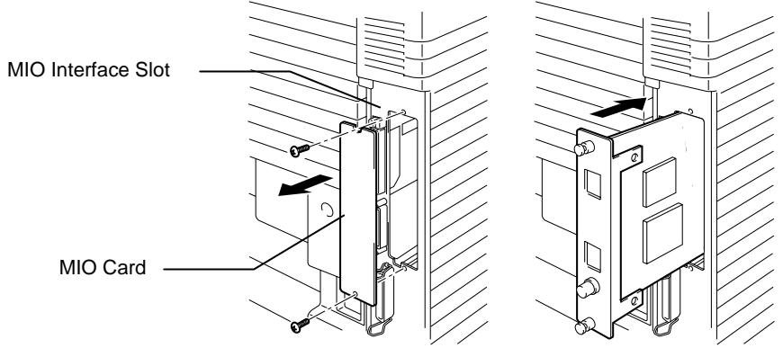
Fig. 5-52 Installing the MIO Card
RAM Expansion
This printer has 32 Mbytes of memory standard and 2 slots for optional expansion memory. The memory can be expanded up to 288 Mbytes by installing commercially available dual in-line memory modules (DIMMs). (The standard memory fitted can vary depending on the printer model and country.)
This printer uses memory modules which are:-
100 pins, no-parity, SDRAM with 64Mbit or more.
This printer is not compatible with Extended Data Output (EDO) DIMM, or DIMM which uses 16Mbit SDRAM.
The following capacity of DIMM can be installed:
• 16 Mbyte TECHWORKS PM-HP 16M-BR
• 32 Mbyte TECHWORKS PM-HP 32M-BR
• 64 Mbyte TECHWORKS PM-HP 64M-BR
• 128 Mbyte TECHWORKS PM-HP 128M-BR
In general, the DIMM must have the following specifications:
Type: 100 pin and 32 bit output
CAS Latency: 2 or 3
Clock Frequency: 66Mhz or more
Capacity: 16,32, 64 or 128 Mbyte
Height: 46mm (1.8 inches) or less
Parity: NONE
Dram Type: 64 M bit SDRAM 4 Bank
SDRAM can be used.
Notes
- There might be some DIMMs which will not work with this printer.
- For more information, consult the dealer where you purchased the printer.
- For the latest information: http://www.brother.com
To install DIMMs, follow these steps:
- Turn off the printer and unplug the power cord from the AC outlet.
Note
Be sure to turn off the power to the printer before installing or removing the DIMMs.
- Unscrew the two screws securing the rear plate of the main controller board and pull out the main controller board.
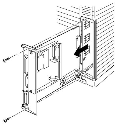
natural_image
Technical line drawing of a mechanical assembly with no visible text or symbolsFig. 5-53 Removing the Main Controller Board
- Unpack the DIMM and hold it by its edge.

Caution
Do not touch the memory chips and the surface of the main controller board. If static electricity collects, it may damage these electrical parts.
- Hold the DIMM with your fingers against the side edges and thumb against the back edge. Align the notches on the DIMM with the DIMM slot. (Check that the locks on each side of the DIMM slot are open, or outward.) .
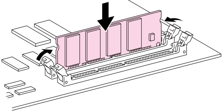
natural_image
Diagram of a computer RAM module with directional arrows indicating movement or force (no text or symbols present)Fig. 5-54 Install the DIMM
- Press the DIMM straight into the slot (press firmly). Make sure the locks on each side of the DIMM snap inwards into place. (To remove a DIMM, the locks must be released.)
Notes
- When you install less than two DIMMs, be sure to install them in the order Slot 1 and then Slot2.
-
When you install different capacities of DIMMs, be sure to install the larger capacity DIMM in Slot1 and smaller capacity DIMM in Slot2.
-
Refit the main controller board into the printer by sliding it into the guide rails.
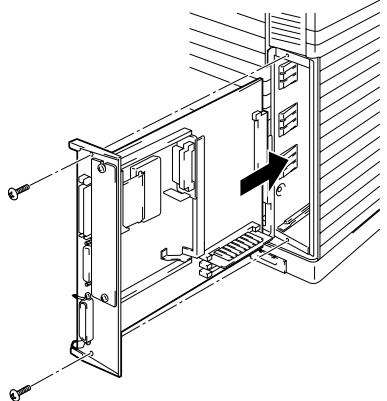
natural_image
Technical line drawing of a mechanical assembly with no visible text or symbolsFig. 5-55 Refit the Main Controller board
- Secure the main controller board with the two screws.
- Reconnect the printer cable from your computer. Plug the power cord into the AC outlet and turn on the printer.
- To check whether the DIMM has been installed correctly, you may perform a Test Print “Print Configuration” that will print the current memory size.
HDD (Hard Disk Drive)
- Turn off the printer and unplug the power cord from the AC outlet.
- Unscrew the two screws securing the rear plate of the main controller board and pull out the main controller board.
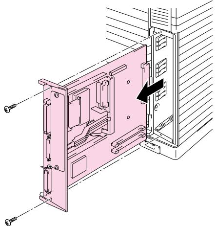
natural_image
Technical diagram of an internal device housing with mounting brackets and a black arrow indicating a component (no text or symbols present)Fig. 5-56 Secure the controller board
- Insert the 4 pillars into the bottom of the 2.5-inch HDD.
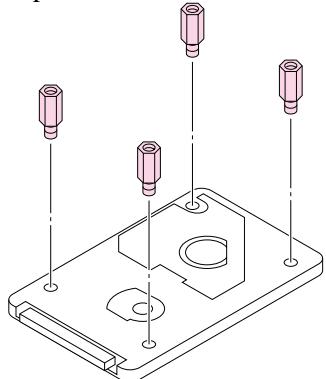
natural_image
Isometric line drawing of a mechanical component with four cylindrical pins and mounting holes (no text or symbols)Fig. 5-57 Insert the 4 pillars
- Connect the cable to the HDD with the keyed side downwards, ensuring it is correctly aligned.
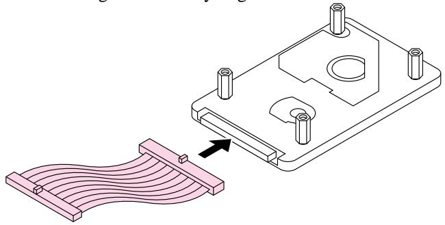
natural_image
Isometric diagram of a mechanical component with a curved spring-like structure and an arrow indicating direction (no text or symbols)Fig. 5-58 connect the HDD
- Fit the 4 HDD pillars into the 4 holes of the main controller board, and secure the pillars with the screws provided from the rear of the PCB.
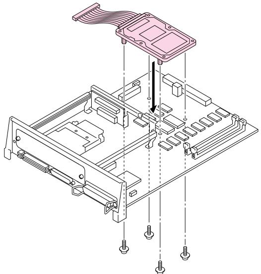
natural_image
Isometric technical diagram of a mechanical assembly with labeled components (no text or symbols)Fig. 5-59 Set the HDD
- Connect the flat cable to the main controller board.
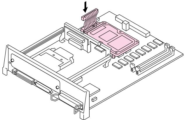
natural_image
Isometric technical diagram of a mechanical assembly with no visible text or symbolsFig. 5-60 Insert the flat cable
- Install the main controller board into the printer by sliding it into the guide rails.
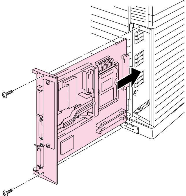
natural_image
Technical line drawing of a mechanical assembly with no visible text or symbolsFig. 5-61 Install the main controller board
- Secure the main controller board with the 2 screws.
- Connect the printer interface cable, AC power cord and turn the printer on.
- Format the HDD from the control panel. See Chapter 4 for details.
CHAPTER 6 TROUBLE SHOOTING
TROUBLESHOOTING
If any problems occur, the printer automatically stops printing, diagnoses the problem, and displays the corresponding message to alert you. Take the appropriate action, referring to the following tables. If you cannot clear the problem, consult the dealer where you purchased the printer. Inform the dealer of the message number for quick troubleshooting.
Operator Call Messages
When any of the following messages appear, the printer stops operating.
| Operator Call Message | Meaning | Action |
| CHECK XXXXXX | Check the paper tray.XXXXXXX is TRAY 1/TRAY 2. | Check that the paper is correctly inserted in the tray when the CHECK TRAY 1 message appears.Load a stack of paper into the cassette. |
| 12 COVER OPEN FRONT | The Front cover of the printer is open. | Close the Front cover. |
| 12 COVER OPEN TOP | The Top cover of the printer is open. | Close the Top cover. |
| 12 COVER OPEN REAR | The Rear Access cover of the printer is open. | Close the Rear Access cover. |
| 13 JAM XXXXXX | Paper is jammed in the printer. XXXXXX is DRUM/TRAYS/INSIDE/REAR. | Remove the jammed paper from the indicated area.See the ‘Paper Jams’ section in this chapter. |
| 14 NO CARTRIDGE XXXX COLOR | A toner cartridge is not installed in the printer. XXXX indicates colors. | Install the toner cartridge. |
| XX NO CASSETTE | The Media Cassette is not installed. XX is T1/T2. | Install the Media Cassette. |
| 16 TONER EMPTY XXXX COLOR | The printer has almost run out of toner: you may print another 50 pages. (The Alarm LED lights at the same time.)XXXX indicates colors. | Remove the toner cartridge, rock it several times at 45°, and install it again or replace the toner cartridge with a new one. |
| XX LOAD PAPER**** SIZE | The wrong size of paper was loaded in the Media Cassette. XX is T1/ T2. | Load the requested size of paper in the Media Cassette and press the Form Feed button. |
| T1 MANUAL FEED**** SIZE | The printer is requesting you to load paper manually. | Load the requested size of paper on the Standard Media Cassette and press the Sel button. |
| 19 CHECK FONT | An error occurred in the optional font card. | Turn off the printer, and re-install or replace the optional font card. |
| 20 FONT REMOVAL | The PCMCIA card was removed while the printer is on-line. | Turn off the printer, install the card, and turn on the printer. The Continue button will allow you to temporarily ignore this message. |
| 22 WASTE TONER | The Waste Toner Pack is full. | Replace the Waste Toner Pack with a new one. |
| 23 OIL EMPTY | The Oil in the Oil Bottle is empty. | Replace the Oil Bottle with a new one. |
| 24 CHANGE FCR | It is time to replace the Fuser Cleaner. | Replace the Fuser Cleaner with a new one. |
| 25 NO FUSER UNIT | The Fusing Unit is not installed correctly. | Install the Fusing Unit correctly. |
| 27 NO OPC BELT | The OPC Belt Cartridge is not installed correctly. | Install the OPC Belt Cartridge correctly. |
| 28 NO FC ROLLER | The Cleaning Roller is not installed correctly. | Install the Cleaning Roller correctly. |
Maintenance Messages (appear on the lower row)
| Error Message | Meaning | Action |
| FUSER OIL LOW | The Oil in the Oil Bottle is almost empty. | Replace the Oil Bottle. |
| REPLACE FCR | It is time to replace the Cleaning Roller. | Replace the Cleaning Roller. |
| REPLACE OPC BELT | It is time to replace the OPC Belt Cartridge. | Replace the OPC Belt Cartridge. |
| REPLACE FUSER | It is time to replace the Fusing Unit. | Replace the Fusing Unit. |
| REPLACE 120K KIT | It is time to replace the Drum Cleaner, Paper Discharger, Transfer Roller, Separation pad and Paper feed roller. | Replace the Drum Cleaner, Paper Discharger, Transfer Roller, Separation pad and Paper feed roller. |
Error Messages
| Error Message | Meaning | Action | ||
| 32 | BUFFER | ERROR | Input buffer overflow | Reset the printer or turn off and on the printer. |
| 34 | MEMORY | FULL | Work memory overflow | Press the Continue button to resume printing. If the same error should occur after you press the Continue button, turn off the printer. Wait a few seconds, then turn it on again. Reduce the input buffer size. Turn off “KEEP PCL.” Add DIMM memory with printer power off. Download font and the fonts saved in the HDD card might cause the error, for these occupy the same work area as the RAM. Memory expansion is recommended in that case. |
| 40 | LINE | ERROR | Error in the communications circuit | When the serial interface is used, check the communications parameters such as baud rate, code type, parity, and handshake protocols. When the parallel interface is used, check the interface cable connection. |
| 41 | CHECK | Error in communication with the engine controller | Turn off the printer. Wait a few seconds, then turn it on again. | |
| Error Message | Meaning | Action |
| 42 DEVICE1(2/3)FULL | Card in slot 1 or 2 or HDD overflow | Delete unnecessary macros or fonts, or use a new device. |
| 43DEVICE1(2/3)WERROR | Card in slot 1 or 2 or HDD write error | Set the write protect button of the card to OFF if it has been set to ON. Use a new card. If the same error occurs, consult your dealer or service provider. |
| 45 MIO ERROR | Error in communication with the MIO card | Install the MIO card correctly. |
| 47DEVICE1(2/3)RERROR | Card in slot 1 or 2 or HDD read error | Use a new device. If the same error occurs, consult your dealer or service provider. |
| IGNORE DATA(BR-Script 2 mode only) | Data is ignored because of an error in the PostScript® language program. | Press the Reset button.If the same error occurs, you may need to add optional DIMM memory. |
Service Call Messages
When any of the following messages appear on the LCD, turn the printer Off, wait 5 seconds and then turn the printer On again. If this does not clear the problem, consult your dealer or our authorized service representative.
| Service Call Message | Meaning | Action | |
| 61 PROG ERROR | Program ROM checksum error | Turn off the printer. Wait a few seconds, then turn it on again. | |
| 62 FONT ERROR | Font ROM checksum error | Turn off the printer. Wait a few seconds, then turn it on again. | |
| 63 D-RAM ERROR | D-RAM error | Turn off the printer. Wait a few seconds, then turn it on again. | |
| 66 NV-W ERROR | NV-RAM write error | Turn off the printer. Wait a few seconds, then turn it on again. | |
| 67 NV-R ERROR | NV-RAM read error | Turn off the printer. Wait a few seconds, then turn it on again. | |
| 68 NV-B ERROR | NV-RAM write / read error | Turn off the printer. Wait a few seconds, then turn it on again. | |
| 88 WARNING C3 | Engine NV-RAM error | Turn off the printer. Wait a few seconds, then turn it on again. | |
| 88 WARNING C4 | Engine controller error | Turn off the printer. Wait a few seconds, then turn it on again. | |
| 88 WARNING C7 | Process timing clock error | Turn off the printer. Wait a few seconds, then turn it on again. | |
| 88 WARNING D1 | Y switching clutch error | Turn off the printer. Wait a few seconds, then turn it on again. | |
| 88 WARNING D2 | M switching clutch error | Turn off the printer. Wait a few seconds, then turn it on again. | |
| 99 SERVICE 0-9 | CPU error | Turn off the printer. Wait a few seconds, then turn it on again. | |
| Service Call Message | Meaning | Action | |
| 88 | WARNING D3 | C switching clutch error | Turn off the printer. Wait a few seconds, then turn it on again. |
| 88 | WARNING D4 | K switching clutch error | Turn off the printer. Wait a few seconds, then turn it on again. |
| 88 | WARNING D5 | K,Y switching solenoid error | Turn off the printer. Wait a few seconds, then turn it on again. |
| 88 | WARNING D6 | C, M switching solenoid error | Turn off the printer. Wait a few seconds, then turn it on again. |
| 88 | WARNING E1 | Developing motor error | Turn off the printer. Wait a few seconds, then turn it on again. |
| 88 | WARNING E2 | Main motor error | Turn off the printer. Wait a few seconds, then turn it on again. |
| 88 | WARNING E3 | Drum error | Turn off the printer. Wait a few seconds, then turn it on again. |
| 88 | WARNING E4 | Toner empty sensor error | Turn off the printer. Wait a few seconds, then turn it on again. |
| 88 | WARNING E5 | Transfer Roller solenoid error | Turn off the printer. Wait a few seconds, then turn it on again. |
| 88 | WARNING E6 | Drum cleaning solenoid error | Turn off the printer. Wait a few seconds, then turn it on again. |
| 88 | WARNING E7 | Drum cleaning clutch error | Turn off the printer. Wait a few seconds, then turn it on again. |
| 88 | WARNING E8 | Fusing Unit clutch error | Turn off the printer. Wait a few seconds, then turn it on again. |
| 88 | WARNING E9 | Belt marker sensor error | Turn off the printer. Wait a few seconds, then turn it on again. |
| 88 | WARNING EL | Erase LED error | Turn off the printer. Wait a few seconds, then turn it on again. |
| 88 | WARNING F0 | Cooling fan error | Turn off the printer. Wait a few seconds, then turn it on again. |
| 88 | WARNING F2 | Ozone fan error | Turn off the printer. Wait a few seconds, then turn it on again. |
| 88 | WARNING F4 | Fuser fan error | Turn off the printer. Wait a few seconds, then turn it on again. |
| 88 | WARNING F5 | Charge HV unit error | Turn off the printer. Wait a few seconds, then turn it on again. |
| 88 | WARNING H0 | Fuser thermistor error | Turn off the printer. Wait 15 minutes, then turn it on again. |
| 88 | WARNING H2 | Fuser temperature error (Warming up time error) | Turn off the printer. Wait 15 minutes, then turn it on again. |
| 88 | WARNING H3 | Fuser temperature error (On time error) | Turn off the printer. Wait 15 minutes, then turn it on again. |
| 88 | WARNING H4 | Fuser temperature error (Off time error) | Turn off the printer. Wait 15 minutes, then turn it on again. |
| 88 | WARNING L1 | Beam detector error | Turn off the printer. Wait a few seconds, then turn it on again. |
| 88 | WARNING L2 | Scanner motor error | Turn off the printer. Wait a few seconds, then turn it on again. |
| 88 | WARNING LL | Laser power error | Turn off the printer. Wait a few seconds, then turn it on again. |
Paper Jams
This printer has been designed to be trouble free. However, if a problem should occur, note the display message and take the appropriate action. This section describes the actions to be taken against paper jams and unsatisfactory printouts.
Paper Jam
If paper jams in the printer, it stops printing and displays the following message.
13 JAM XXXXXX
Note
Do not use the following paper:
- Bent paper
- Moist paper
• Paper that does not meet specifications
Paper may jam in the Media Cassette, inside the printer, at the Rear Access Cover or at the paper exit. Check the jam location and follow the instructions below to remove the jammed paper.
After you have followed the instructions, the printer automatically resumes printing. However, the Data LED may come on and the following message may appear on the display:
07 FF PAUSE
After a paper jam has occurred, data usually remains in the printer memory. The message prompts you to execute a form feed and print the remaining data. Press the Set button to continue.
■ Paper Jam at Paper Exit
13 JAM REAR
If paper has passed behind the Rear Access Cover and a paper jam has occurred at the paper exit, follow the steps below:
- Open the Top Cover and release the Fusing unit Pressure Release Levers.
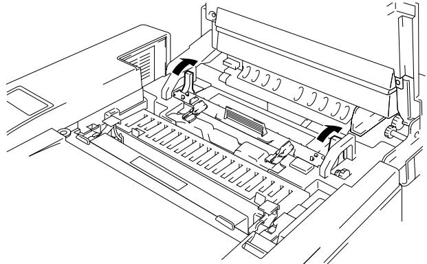
natural_image
Technical line drawing of a printer internal structure (no text or symbols)Fig. 6-1 Paper Jam at Paper Exit
- Open the Rear Access Cover and remove the jammed paper by pulling it out slowly.
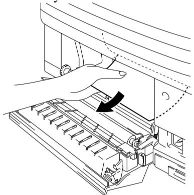
natural_image
Line drawing of a hand operating a mechanical device with a black arrow indicating the process (no text or symbols present)Fig. 6-2 Remove the jammed paper
- Close the Rear Access Cover.
- Reset the Fusing unit Pressure Release Levers and close the Top Cover.
Note
When paper jams at the Rear Access Cover increase, replace the Paper Discharger.
■ Paper Jam at Fusing Roller inside the printer
13 JAM INSIDE
or
13 JAM DRUM
If a paper jam occurs at the Fusing Roller, follow the steps to remove the jammed paper in the same way as for ‘Paper Jam at Paper Exit’. Otherwise, follow the steps below:

Warning
The Fusing Roller is extremely HOT during operation. Remove the paper carefully.
- Open the Rear Access Cover.
- Remove the jammed paper by holding it with both hands and pulling it slowly toward you.
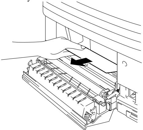
natural_image
Line drawing of a hand pressing down on a mechanical device with a black arrow indicating motion (no text or symbols)Fig. 6-3 Clearing Inside Paper Jam
- Close the Rear Access Cover.

Caution
- Do not touch the toner surface of the jammed paper. It might stain your hands or clothes.
- After removing the jammed paper, if the next printed paper is stained with toner, print several test pages before restarting your print job.
- Remove the jammed paper carefully to prevent spreading toner.
- Take care not to stain your hands and clothes. Wash toner stains immediately with cold water.
• Never touch the transfer roller. - If the edge of print paper is creased, paper jams can occur. To avoid this, please turn the paper over in the media cassette.
■ Paper Jam in the Media Cassette
13 JAM TRAYS
If a paper jam occurs inside the Media Cassette, follow these steps:
- Pull out the Media Cassette.
- Remove the jammed paper.
natural_image
Technical line drawing of a mechanical assembly with dashed and dotted lines indicating internal components (no text or symbols)Fig. 6-4 Paper Jam in Media Cassette
- Re-install the Media Cassette.

Caution
Do not remove the upper Media Cassette while printing from the optional lower Media Cassette. This will cause a paper jam.
Q & A
This section contains commonly asked questions and the answers concerning your HL-2400Ce printer. If you have encountered a problem, find your question below and follow the recommended steps:
Setting Up the Printer Hardware
| Question | Recommendation |
| The printer does not come on. | Check the following:• The printer is securely plugged into the AC outlet.• The power source is active.• ThePowerbutton is on. |
| The printer does not print. | Check the following:• The printer is turned On.• The printer is Online.• All of the protective parts have been removed.• All the covers on the printer are closed.• The toner cartridges are installed properly.• The ‘toner empty’ message is not displayed on the LCD. If one or more are on, replace the toner cartridges.• The interface cable is securely connected between the printer and computer.• TheAlarmLEDis blinking. If the LED is blinking, refer to theOperator Call sectionof this manual.• The HL-2400Ce printer is selected in the printer settings in your application.• The host is configured correctly: check printer port, print manager etc. (clear stored job or ‘use print manager’ is selected off)• There is no jammed paper inside the printer.• Paper is loaded in the Media Cassette.• An Error message is not displayed. |
Setting Up the Printer
| Question | Recommendation |
| I cannot print from my application software. | Make sure the supplied Windows printer driver is installed correctly and selected in your application software. |
| I cannot print the entire page. | Check to see if the size of paper in the feeder is the same as the one that you have selected in your application or the printer driver.Check to see if the interface cable is connected to the printer and computer securely. |
| Computer indicates a device time-out. | If the Alarm LED is blinking, clear it referring to the ‘Alarm Indications at a Glance’ section in this chapter and try to print again.If the Alarm LED is off, wait a short while and then click on the Retry button on the PC screen dialog box.Check to see if the printer is On-line |
| Computer indicates Paper Empty. | Paper is empty. Load paper in the Feeder and push the On Line button to recover from the error status.. |
| Computer indicates Off Line | Press the On Line button to make the printer ready. |
| Computer indicates Power Off | Check if the printer is securely plugged into the AC outlet and the Power button is On. |
| Computer indicates an error message other than above. | Check the following;The computer can work in bi-directional mode.The printer port is correct.Selection of the printer is correct.Recommended interface cable is being used.(IEEE 1284 compliant)Or select the ‘Control’ tag in the driver and set the ‘Status Monitor’ to off. |
| If you install the printer driver for your HL-2400Ce from the Plug & Play installation, the installation may sometimes fail with the following error dialog.C:\WINDOWS\~BR00002.txtC:\WINDOWS\~BR00002.txtOK | Please reinstall the printer driver by clicking the ‘Add Printer’ icon on the Settings-Printer dialog. |
Paper Handling
| Question | Recommendation |
| The printer does not load paper. | ·Check to see if the Alarm LED is on. If so, the Media Cassette may be out of paper or not properly installed. If it is empty, load a new stack of paper into the Media Cassette. ·If there is paper in the Media Cassette, make sure that it is straight. If the paper is curled, you should straighten it before printing. Sometimes it is helpful to remove the paper, turn the stack over and replace it in the paper tray. ·Reduce the stack of paper in the Media Cassette, then try again. |
| How can I load envelopes? | You can load envelopes from the Media Cassette. Make sure you adjust the paper guide. Your application software also must be set up correctly to print on the envelope size you are using. This is usually done in the page setup or document setup menu of your software. Refer to your applications manual for further information. |
| What paper can I use? | See ‘Paper Handling’ in Chapter 3 for detailed paper specifications. |
| How can I clear paper jams? | See the “PAPER JAMS” section in this chapter. |
| The printer loads more than one sheet at a time. | Check to see if: ·The paper loaded is all the same type. ·Paper that meets the specifications is loaded. ·Papers were fanned before loading. ·The stack of paper is not too high. ·The side guide is not set too tight. |
| The printer doesn’t eject paper. | Set the printer Off-line, then push the Form Feed button. Then push the On Line button. |
| Paper loads skewed. | Check the following: ·The side guide is adjusted correctly. ·The amount of paper you have loaded is correct. Refer to the ‘Loading Paper in the Media Cassette’ section in Chapter 2. |
| Sometimes mis-picking of paper from the paper tray or mis-feeding of paper from the paper exit occurs. | Clean the Paper Guide, the Registration Roller and the Exit Roller referring to ‘Periodical Printer Cleaning’ in Chapter 5. |
Printing
| Question | Recommendation |
| The printer prints unexpectedly or it prints incorrect characters. | Cancel the print job from your computer. Then, turn on and off the printer or reset the printer and try your print job again.Make sure your application software is correctly set up to use this printer and check the printer driver settings or printer settings in your application software. |
| The computer hangs up when the printer starts printing, or an application error occurs. | Check to see if the system resources are enough (PC memory, etc). When you have many applications open, the system resources of your PC will not be enough and your PC will hang up. Close applications you are not using and try again. |
| My headers or footers appear when I view my document on screen but do not show up when I print them. | Most laser printers have a restricted area that cannot be printed on. Adjust the top and bottom margins in your document to allow for this. |
| Printing takes too long. | When you print color graphic images, there is a large amount of data and the printer will take a relatively long time to complete printing.When you print in Super Fine mode, the printer will take a relatively long time to finish printing.When the Data LED is blinking, the printer is making itself ready to print. Printing speed depends on memory size or performance of your PC and memory size of the printer. |
| The printer doesn’t print in color | The printer may be set in monochrome mode.Check that the color toner(s) have not run out. |
Print Quality
Note
You can resolve a print quality problem by replacing a toner cartridge with a new one if the LCD indicates the ‘toner low’ or ‘toner empty’ message.
| Question | Recommendation | |
White horizontal lines or bands or rubbing | 1) Check the printer is installed on a solid, level surface.2) Check the rear access cover is closed correctly.3) Check the toner cartridges are installed correctly.4) Shake the toner cartridges gently | |
Colors are light or unclear in the whole page | 1) Check the specified paper is used.2) Check if the problem is solved after changing the paper to freshly unpacked paper.3) Check the rear access cover is closed correctly.4) Shake the toner cartridges gently | |
White vertical streaks or bands |  | Check which color is missing and replace the toner cartridge*The toner has probably come to the end of its life. However, when you see a white vertical line on the toner roller, try the following procedure.1. Cut a sheet approx. 50mm x 50mm out of a transparency film.2. Insert the film about 10mm into the gap between the toner roller and the blade.3. Slide the film and pull it out as shown below.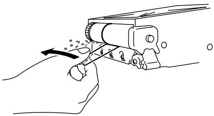 |
| Question | Recommendation |
Black vertical streaks or bands  | 1) Check which color is missing and replace the toner cartridge2) Replace the OPC belt cartridge |
Black (colored) horizontal lines  | Check which color is missing and replace the toner cartridge. |
White spots or hollow print | 1) Check if the problem is solved after changing the paper to freshly unpacked paper.2) Check the specified paper is used.3) Check the room temperature is higher than 10 degrees C. |
Completely blank or some colors are missing ▶ ▶  | 1) Check which color is missing and check the toner cartridge is installed correctly.2) Replace the toner cartridge3) Replace the OPC belt cartridge |
Black (colored) spots or Toner stain | Contact your dealer or Brother authorized service representative. |
Toner scatter or Toner stain | 1) Check which color is the problem and replace the toner cartridge2) Replace the OPC belt cartridge |
| The color of your printouts are not what you expected | 1) Initiate a test print from the control panel.2) Check that the toner cartridges are installed correctly.3) Check that toner cartridges are not empty.4) Adjust the color by using the custom setting in the driver. Colors the printer can display and colors you see on a monitor are different. The printer may not be able to reproduce the colors on your monitor.5) Check to ensure the specified paper is used. |
| All one color | Replace the OPC belt cartridge |
Dirt on back of paper  | 1) Replace the Oil Bottle2) Replace the Fuser Cleaning Roller |
| Shade on the transparency | 1) Check that the problem is solved after changing to the recommended type of transparency.2) Check that the media type mode is selected correctly |
Color misregistration | 1) Check that the OPC Belt Cartridge is installed correctly.2) Replace the OPC Belt Cartridge |
Uneven density appears periodically in the horizontal direction  | 1) Check that the toner cartridges are installed correctly.2) Check that the OPC Belt Cartridge is installed correctly. |
Missing image at edge  | 1) Replace the toner cartridge.2) Replace the OPC Belt Cartridge. |
Wrinkle  | 1) Check that the problem is solved after changing to a recommended type of paper.2) Check that the rear access cover is closed correctly.3) Check that the paper discharger is installed correctly. |
Mixed color image  | 1) Check that the front cover is closed correctly.2) Check that the toner cartridges are installed correctly.3) Replace the toner cartridges. |
| Insufficient Gloss | 1) Check that the oil is not empty.2) Replace the Fuser Cleaning Roller.3) Check that the specified paper is being used. |
Off set image | 1) Check that the specified paper is being used.2) Check that the oil is not empty.3) Replace the Fuser Cleaning Roller |
Poor fixing | 1) Check that the specified paper is used.2) Check that the media type mode is selected correctly. |
| Poor fixing | Wait 15 to 30 minutes and try again. |
| Poor fixing when printed on thick paper | Set the printer to thick paper mode through the control panel or the printer driver. |
Blurred vertical band and spots of color. | Clean the Charging Wire as shown below:1. Open the Front Cover and take the Cleaning Brush out of the printer.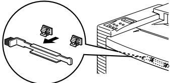 2. Open the Top Cover and take the (OPC) Belt Cartridge out of the printer.3. Brush the Charging Wire with the Cleaning brush as shown below. 2. Open the Top Cover and take the (OPC) Belt Cartridge out of the printer.3. Brush the Charging Wire with the Cleaning brush as shown below.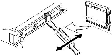 |
Dirt on the printed paper.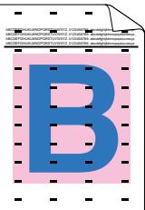 | Clean the Paper Guide, the Registration Roller and the Exit Roller referring to ‘Periodic Printer Cleaning’ in Chapter 5. |
If the same problem re-occurs, contact your dealer or Brother authorized service representative.

Caution
Operation of the printer outside the specifications shall be deemed abuse and all repairs thereafter shall be the sole liability of the end user/purchaser.
(For USA & CANADA Only)
For technical and operational assistance, please call:
In USA 1-877-284-3238
In CANADA 1-800-853-6660
514-685-6464
(within Montreal)
If you have comments or suggestions, please write us at:
In USA Printer Customer Support
Brother International Corporation
15 Musick
Irvine, CA 92618
In CANADA Brother International Corporation (Canada), Ltd.
- Marketing Dept.
For downloading drivers from our Bulletin Board Service, call:
In USA 1-888-298-3616
In CANADA 1-514-685-2040
Please log on to our BBS with your first name, last name and a four digit number for your password. Our BBS supports modem speeds up to 14,400, 8 bits no parity, 1 stop bit.
Fax-Back System
Brother Customer Service has installed an easy to use Fax-Back System so you can get instant answers to common technical questions and product information for all Brother products. This is available 24 hours a day, 7 days a week. You can use the system to send the information to any fax machine, not just the one you are calling from.
Please call 1-800-521-2846 (USA) or 1-800-681-9838 (Canada) and follow the voice prompts to receive faxed instructions on how to use the system and your index of Fax-Back subjects.
DEALERS/SERVICE CENTERS (USA only)
For the name of an authorized dealer or service center, call 1-800-284-4357.
SERVICE CENTERS (Canada only)
For service center addresses in Canada, call 1-800-853-6660
INTERNET ADDRESS
For technical questions and downloading drivers: http://www.brother.com
APPENDICES
PRINTER SPECIFICATIONS
Printing
| Print Method | Electrophotography by semiconductor laser beam scanning |
| Laser | Wavelength: 780 nmOutput: 5mW max. |
| Resolution | 300x300 dots per inch (Draft)600x600 dots per inch (Fine)1200x600 dots per inch2400x600 dots per using CAPT and HRC(The resolution can be enhanced to 2400 dpi class by using Brother exclusive HRC (High Resolution Control) and (Color Advanced Photoscale Technology) |
| CAPT | |
| Print Speed | 16 pages per minute (A4/Letter size in monochrome)4 pages per minute (A4/Letter size in full color) |
| Warm Up | Max. 3 minutes at 20°C (68°F) |
| First Print | Monochrome: 19 seconds or lessFull Color: 30 seconds or less(A4/Letter size by face down print delivery from standard upper cassette feed) |
| Consumables | Toner in a single color single-component cartridgeLife Expectancy: 10,000 (Black): 6,000 (Cyan, Magenta and Yellow) single-sided pages/cartridge (A4 or letter size paper with about 5% coverage). |
| Resident Printer Fonts | 72 scalable fonts, 12 bitmapped fonts, 11 barcode fonts |
Functions
| CPU | VR4310 |
| Emulation | Automatic emulation selectionHP Color Printer (PCL5C) including HP LaserJet 4+ (PCL 5e) and HP LaserJet 5 (PCL 6) monochrome modeBR-Script Level 2 (Adobe Postscript Level 2 compatible)HP-GLEPSON FX-850IBM Proprinter XL |
| Interface | Automatic interface selection among bi-directional parallel, RS-232C serial, NC-3100h and MIO interface. |
| RAM | 32 Mbyte(expandable to 288Mbytes with DIMMs)The standard memory fitted can vary depending on the printer model and country. |
| HDD option | 2.5 inch IDE HDD |
| Card Slots | 2 slots for PCMCIA Type I, II1 card slot: PCMCIA Type III Compatible for FLASH Memory or HDD cards |
| Control Panel | 8 switches, 4 lamps and 16-column by 2-lines liquid crystal display |
| Diagnostics | Self-diagnostic program |
Electrical and Mechanical
| Power Source | U.S.A. and Canada: | AC 120 V, 50/60 Hz |
| Europe and Australia: | AC 220 to 240V, 50/60 Hz | |
| Power Consumption | Printing (Average): | 450 W or less |
| Stand-by: | 150 W or less | |
| Stand-by in sleep mode: | 35 W or less | |
| Noise | Printing: | 55 dB A or less |
| Stand-by: | 48 dB A or less | |
| Temperature | Operating: | 10 to 32.5°C (50°F to 90.5°F) |
| Non operational: | 5 to 35°C (41°F to 95°F) | |
| Storage: | 0 to 35°C (38°F to 95°F) | |
| Humidity | Operating: | 20 to 80% (without condensation) |
| Storage: | 20 to 80% (without condensation) | |
| Dimensions (W x H x D) | 500 x 388 x 490 mm (19.5 x 15.3 x 19.3 inches) | |
| 500 x 493 x 490 mm (19.5 x 19.4 x 19.1 inches) with an optional lower tray unit fitted | ||
| Weight | Approx. 37 kg (81.6 lbs.) | |
| Approx. 42.5 kg (93.7 lbs.) with optional lower tray unit and toner cartridges installed. | ||
PAPER SPECIFICATIONS
Paper Input
Media Trays :
• Standard upper tray (Tray 1)
- Optional lower tray (Tray 2)
- Paper size:
TRAY 1: Letter, A4, ISO B5, JIS B5, Executive, A5, COM10, DL and ISO B5
TRAY 2: Letter, A4, ISO B5, JIS B5, Executive, A5, (Legal for Optional Legal Cassette)
- Max. stacking height in the cassette = 27 mm(1.06")
- Max. paper cassette capacity = Approx. 250 sheets of 75g / m^2 (20 lbs)
Printed Output
Face down print delivery
Paper Type
Standard upper tray (Tray 1):
- Plain paper of letter, A4, ISO B5, JIS B5, A5, and Executive sizes 100 x 210 mm to 216 x 297 mm (3.9 x 8.2" to 8.5 x 11.7") [60 to 160 g/m² (16 to 43 lbs)]
• Envelopes of COM10 DL sizes
- Transparencies
- label stocks
Optional lower tray (Tray 2):
- Plain paper of letter, A4, ISO B5, JIS B5, A5, and Executive sizes 100 x 210 mm to 216 x 297 mm (3.9 x 8.2" to 8.5 x 11.7") [60 to 160 g/m² (16 to 43 lbs)]
- label stocks
Optional legal tray (Tray 1/2):
- Plain paper of letter, legal, A4, ISO B5, JIS B5, A5, and Executive sizes 100 x 210 mm to 216 x 356 mm (3.9 x 8.2" to 8.5 x 14") [60 to 160 g/m² (16 to 43 lbs)]
- Envelopes of COM10 and DL sizes
- Transparencies
- label stocks
Test printing on paper, especially envelopes, is recommended before making a large purchase. The following types of envelopes are not recommended for use.
- Envelopes with thick and/or crooked edges
- Damaged, curled, wrinkled, or irregularly shaped envelopes
- Extremely shiny or highly textured envelopes
- Envelopes with clasps
- Envelopes of baggy construction
- Envelopes not sharply creased
- Embossed envelopes
- Envelopes already printed with a laser printer
- Envelopes that cannot be arranged uniformly when placed in a pile
Notes
- An area 15 mm (0.6") from the edges of the envelope will not be printed.
- Avoid feeding labels with the carrier sheet exposed otherwise your printer will be damaged.
- When feeding OHP film, the use of a recommended type for laser printers will ensure optimum printing. For detailed information on the specification or purchase, please contact your nearest authorized sales representative or the place of purchase.
PAPER
The printer is designed to work well with most types of xerographic and bond paper. However, some paper variables may have an effect on print quality or handling reliability. Always test samples of paper before buying to ensure that it provides desirable performance. Some important guidelines when selecting paper are:
- Supplier should be informed that the paper or envelopes will be used in a laser printer.
- Preprinted papers must use inks that can withstand the temperature of the printers fusing process. (200 degrees centigrade)
- If you have selected a cotton bond paper, paper having a rough surface such as cockle or laid finished paper or paper that is wrinkled or puckered, these types of paper may exhibit degraded performance.
Note
The manufacturer does not warrant the use of any particular paper. The operator is responsible for the quality of paper used with the printer.
Paper Types to Avoid
Some types of paper might not perform well or may cause damage to your printer.
Types of paper to avoid are:
- Highly textured paper.
- Smooth or shiny paper.
- Paper that is coated or has a chemical finish.
- Damaged, wrinkled or pre-folded paper.
- Paper exceeding the recommend weight specification specified in the manual.
- Paper with tabs and staples.
- Letterheads using low temperature dyes or thermography.
- Multipart or carbonless paper.
DAMAGE OR OTHER DEFECTS CAUSED BY THE USE OF PAPERS LISTED UNDER “PAPER TYPES TOAVOID” WILL NOT BE COVERED UNDER ANY WARRANTY OR SERVICE AGREEMENTS.
■ ENVELOPES
Most envelopes will perform acceptably on your printer. However; some envelopes will have feeding and print quality problems because of their construction. A suitable envelope should have edges with a straight, well creased folds and should not have more than two thickness of paper along the lead edge. The envelope should lie flat and not have baggy or flimsy construction. Purchase quality envelopes only from a supplier who understands that the envelopes will be used in a laser printer. All envelopes should be tested prior to use to ensure desirable print results.
Envelope Types to Avoid
- Envelopes constructed with a paper with a weight that exceeds the paper weight specifications for the printer.
- Poorly manufactured envelopes with edges that are not straight or consistently square.
- Envelopes with "baggy" construction or folds that are not sharply creased.
-
Envelopes with transparent windows, holes, cutouts or perforations.
-
Envelopes with clasps, snaps or tie strings.
- Envelopes made with smooth or shiny paper.
- Envelopes that are rough, highly textured, or deeply embossed.
- Envelopes that do not lie flat or that are curled, wrinkled, or irregularly shaped.
- Envelopes having an open flap with an adhesive that seals the envelope.
USE OF ANY OF THE ENVELOPES LISTED ABOVEMAY CAUSE DAMAGE TO YOUR PRINTER. SUCH DAMAGE IS NOT COVERED UNDER ANY WARRANTY OR SERVICE AGREEMENT.
Note
The manufacturer neither warrants nor recommends the use of a particular envelope because envelope properties are subject to change by the envelope manufacturer. The entire responsibility for the quality and performance of the envelope lies with the customer.
■ LABELS AND OVERHEAD TRANSPARENCIES
The printer will print on most type of labels and transparencies designed for use with a laser printer. Labels should have an adhesive that is acrylic-based since such material is more stable at the high temperatures in the fusing unit. Adhesives should not come in contact with any part of the printer, because the label stock may stick to the drum or rollers and cause jams and print quality problems. No adhesive should be exposed between the labels. Labels should be arranged so that they cover the entire page with the only exposed spaces being lengthwise down the sheet. Using labels with spaces may result in labels peeling off and causing serious jam or print problems.
All labels and transparencies used in this printer must be able to withstand a temperature of 200 degrees centigrade (392 degrees Fahrenheit) for a period of 0.1 seconds.
Label and transparency sheets should not exceed the paper weight specifications described in the User's Guide. Labels and transparencies exceeding this specification may not feed or print properly and cause damage to your printer.
The entire responsibility for the quality and performance of labels and transparencies lies with the customer.
DAMAGE CAUSED BY THE USE OF UNSATISFACTORY LABELS OR TRANSPARENCIES IS NOT COVERED UNDER ANY WARRANTY OR SERVICE AGREEMENTS.
Bi-directional Parallel Interface
Interface Connector
A shielded cable that is IEEE 1284 compliant with the following pin assignment should be used. Most standard parallel cables support bidirectional communication, but some might have incompatible pin assignments or may not be IEEE 1284 compliant.
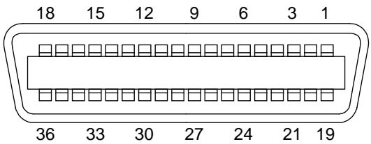
Fig. A-1 Parallel Interface Connector
Pin Assignment
| Pin No. | Signal | Pin No. | Signal |
| 1 | DATA STROBE | 19 | Twisted pair ground |
| 2 | DATA 0 | 20 | Twisted pair ground |
| 3 | DATA 1 | 21 | Twisted pair ground |
| 4 | DATA 2 | 22 | Twisted pair ground |
| 5 | DATA 3 | 23 | Twisted pair ground |
| 6 | DATA 4 | 24 | Twisted pair ground |
| 7 | DATA 5 | 25 | Twisted pair ground |
| 8 | DATA 6 | 26 | Twisted pair ground |
| 9 | DATA 7 | 27 | Twisted pair ground |
| 10 | ACKNLG | 28 | Twisted pair ground |
| 11 | BUSY | 29 | Twisted pair ground |
| 12 | PE | 30 | INPUT PRIME RET |
| 13 | SLCT | 31 | INPUT PRIME |
| 14 | AUTO FEED | 32 | FAULT |
| 15 | N.C. | 33 | N.C. |
| 16 | 0V | 34 | N.C. |
| 17 | 0V | 35 | N.C. |
| 18 | +5V | 36 | SELECT IN |
Signal Description
| Pin No. | Signal Name | IN/OUT | Explanation |
| 1 | DATA STROBE | IN | Data is latched at the leading edge of this signal. |
| 2 - 9 | DATA 0 - 7 | IN | Parallel 8 bit data |
| 10 | ACKNLG | OUT | Data reception is completed and the printer is ready for the next data reception when this signal becomes low. |
| 11 | BUSY | OUT | The printer cannot receive data when this signal is high. The signal becomes high under data receiving, off-line, or error states. |
| 12 | PE | OUT | This signal becomes high when a paper empty state is detected. |
| 13 | SLCT | OUT | This signal becomes high when the printer is selected and low when it is deselected. |
| 14 | AUTO FEED | IN | This signal is used only for the bi-directional interface. |
| 31 | INPUT PRIME | IN | This signal is used only for the bi-directional interface. |
| 32 | FAULT | OUT | This signal becomes low when the printer is in the paper empty, off-line, or error states. |
| 36 | SLCT IN | IN | This signal is used only for the bi-directional interface. |
Parallel Cable Connection for IBM-PC/AT or Compatible Computers and IBM-PS/2 Computers
| Signal | Printer Pin No. | Computer Pin No. |
| DATA STROBE | 1 | 1 |
| DATA 0 | 2 | 2 |
| DATA 1 | 3 | 3 |
| DATA 2 | 4 | 4 |
| DATA 3 | 5 | 5 |
| DATA 4 | 6 | 6 |
| DATA 5 | 7 | 7 |
| DATA 6 | 8 | 8 |
| DATA 7 | 9 | 9 |
| ACKNLG | 10 | 10 |
| BUSY | 11 | 11 |
| PE | 12 | 12 |
| SLCT | 13 | 13 |
| AUTO FEED | 14 | 14 |
| GND | 19 - 30 | 18 - 25 |
| FAULT | 32 | 15 |
| SLCT IN | 36 | 17 |
RS-232C Serial Interface
Standard Specifications
1) Baud rate: 150, 300, 600, 1200, 2400, 4800, 9600, 19200, 38400, 57600 or 115200 baud
2) Synchronization: Start-stop
3) Communications control: No protocol
4) Data length: Serial 7 bits or 8 bits
5) Parity: Odd, even, or none
6) Stop bit: 1 or 2 stop bits
7) Protocol: Xon/Xoff or DTR
Interface Connectors
A shielded cable should be used.
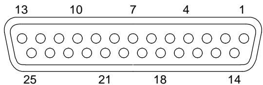
Fig. A-2 Serial Interface Connector
Pin Assignment
| Pin No. | Signal | IN/OUT | Pin No. | Signal | IN/OUT | ||
| Printer | Controller | Printer | Controller | ||||
| 1 | FG | ←→ | 14 | NC | |||
| 2 | SD | → | 15 | NC | |||
| 3 | RD | ←→ | 16 | NC | |||
| 4 | RS | → | 17 | NC | |||
| 5 | NC | 18 | NC | ||||
| 6 | DR | ←→ | 19 | NC | |||
| 7 | SG | ←→ | 20 | ER | → | ||
| 8 | NC | 21 | NC | ||||
| 9 | NC | 22 | NC | ||||
| 10 | NC | 23 | NC | ||||
| 11 | NC | 24 | NC | ||||
| 12 | NC | 25 | NC | ||||
| 13 | NC | ||||||
Signal Description
| Signal Name | IN/OUT | Explanation |
| FG | - | Frame Ground |
| SD | OUT | Send Data. |
| RD | IN | Receive Data. Receives data transmitted from the computer. |
| RS | OUT | Request To Send. “SPACE” level when the printer is ready to send data to the computer. |
| DR | IN | Data Set Ready. When DSR is at “SPACE” level, data can be accepted. |
| SG | - | Signal Ground |
| ER | OUT | Data Terminal Ready. “MARK” level when the printer is Busy. |
Serial Cable Connection for IBM-PC/AT or Compatible Computers and IBM-PS/2 Computers
The following diagrams show the pin connections for the most common serial communications.
■ DB-9 Serial Connection
When you use a computer with a 9-pin serial port, use a cable with the following pin configurations.
| Printer (Male) | Computer (Female) | |||
| SD | 2 | 2 | RD | |
| RD | 3 | 3 | SD | |
| DR (DSR) | 6 | 4 | ER (DTR) | |
| SG | 7 | 5 | SG | |
| ER (DTR) | 20 | 6 | DR (DSR) | |
| 8 | CS (CTS) | |||
■ DB-25 Serial Connection
When you use a computer with a 25-pin serial port, use a cable with the following pin configurations.
| Printer (Male) | Computer (Female) | |||
| FG | 1 | 1 | FG | |
| SD | 2 | 3 | RD | |
| RD | 3 | 2 | SD | |
| DR (DSR) | 6 | 20 | ER (DTR) | |
| SG | 7 | 7 | SG | |
| ER (DTR) | 20 | 5 | CS (CTS) | |
| 6 | DR (DSR) | |||
Note
Any pins not shown in the figures above are not connected.
Network Interface
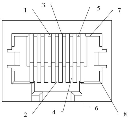
Fig. A-3 10/100Base TX Port
Pin Assignment
| RJ45 pin | Signal |
| 1 TX+ | Transmit Data + |
| 2 TX- | Transmit Data - |
| 3 RX+ | Receive Data + |
| 4 | N.C. |
| 5 | N.C. |
| 6 RX- | Receive Data - |
| 7 | N.C. |
| 8 | N.C. |
For more information, see the “Network User’s Guide” on the CD-ROM.
SYMBOL/CHARACTER SETS
You can select the symbol and character sets with the F ONT switch in the HP LaserJet, EPSON FX -850, and IBM Proprinter X L emulation modes. See “FONT Button” in Chapter 4.
When you have selected the HP-GL emulation mode, you can select the standard or alternate character set with the MOD E switch. See “GRAPHICS MODE” in Chapter 4.
OCR Symbol Sets
When the OCR -A or OCR -B font is selected, the corresponding symbol set is always used.
OCR-A
OCR-B
USER'S GUIDE
HP PCL Mode
Roman 8 (8U)
ISO Latin1 (0N)
ISO Latin2 (2N)
ISO Latin5 (5N)
APPENDICES
PC-8 (10U)
PC-8 D/N (11U)
PC-850 (12U)
PC-852 (17U)
USER'S GUIDE
PC-8 Turkish (9T)
Windows Latin1 (19U)
Windows Latin2 (9E)
Windows Latin5 (5T)
Legal (1U)
Ventura Math (6M)
Ventura Intl (13J)
Ventura US (14J)
USER'S GUIDE
PS Math (5M)
PS Text (10J)
Math-8 (8M)
Pi Font (15U)
MS Publishing (6J)
Windows 3.0 (9U)
Desktop (7J)
MC Text (12J)
Symbol (19M)
Windings (579L)
The following table shows characters available only in the corresponding character set. The numbers at the top of the table are hexadecimal code values with which characters are to be replaced in the Roman 8 character set. For other characters, see the Roman 8 character set.
SYMBOL SET
ISO 2 IRV
ISO 4 UK
ISO 6 ASCII
ISO10 SWE/FIN
ISO11 Swedish
ISO14 JISASCII
ISO15 Italian
ISO16 POR
ISO17 Spanish
ISO21 German
ISO25 French
ISO57 Chinese
ISO60 NOR v1
ISO61 NOR v2
ISO69 French
ISO84 POR
ISO85 Spanish
HP German
HP Spanish
23 24 40 5B 5C 5D 5E 60 7B 7C 7D 7E
EPSON Mode
US ASCII
The following table shows characters available only in the corresponding character set. The numbers at the top of the table are hexadecimal code values with which characters are to be replaced in the US ASCII character set. For other characters, see the US ASCII character set.
| CHARACTER SET | 23 | 24 | 40 | 5B | 5C | 5D | 5E | 60 | 7B | 7C | 7D | 7E |
| German | ||||||||||||
| UK ASCII I | ||||||||||||
| French I | ||||||||||||
| Danish I | ||||||||||||
| Italy | ||||||||||||
| Spanish | ||||||||||||
| Swedish | ||||||||||||
| Japanese | ||||||||||||
| Norwegian | ||||||||||||
| Danish II | ||||||||||||
| UK ASCII II | ||||||||||||
| French II | ||||||||||||
| Dutch | ||||||||||||
| South African |
USER'S GUIDE
PC-8
PC-8 D/N
PC-850
PC-852
APPENDICES
PC-860
PC-863
PC-865
PC-8 Turkish
USER'S GUIDE
IBM Mode
PC-8
PC-8 D/N
PC-850
PC-852
APPENDICES
PC-860
PC-863
PC-865
PC-8 Turkish
USER'S GUIDE
HP-GL Mode
ANSI ASCII
9825 CHR. SET
APPENDICES
FRENCH/GERMAN SCANDINAVIAN SPANISH/LATIN JIS ASCII
USER'S GUIDE
ROMAN8 EXT.
ISO IRV
ISO SWEDISH
ISO SWEDISH:N
APPENDICES
ISO NORWAY 1
ISO GERMAN
ISO FRENCH
ISO U.K.
USER'S GUIDE
ISO ITALIAN
ISO SPANISH
ISO PORTUGUESE
ISO NORWAY 2
Symbol Sets Supported by the Printer's Intellifont Compatible Typefaces
*These symbol sets are variations of the Roman-8 symbol set.
*These symbol sets are variations of the Roman-8 symbol set.
**LetterGothic 16.66 is a bitmapped font.
Symbol Sets Supported by the Printer's TrueType™ and Type 1 Font Compatible, and Original Typefaces
| PCL Symbol Set | TypefaceAtlanta | BRSymbol | Copenhagen | Calgary | Helsinki | Portugal | Tennessee | W Dingbats | |
| Set ID | Symbol Set | ||||||||
| 8U | Roman-8 | • | • | • | • | • | • | ||
| 0N | ISO 8859-1 Latin1 | • | • | • | • | • | • | ||
| 2N | ISO 8859-2 Latin2 | • | • | ||||||
| 5N | ISO 8859-9 Latin5 | • | • | ||||||
| 6N | ISO 8859-10 Latin6 | • | • | ||||||
| 10U | PC-8 | • | • | • | • | • | • | ||
| 11U | PC-8 D/N | • | • | • | • | • | • | ||
| 12U | PC-850 | • | • | • | • | • | • | ||
| 17U | PC-852 | • | • | ||||||
| 26U | PC-775 | • | • | ||||||
| 9T | PC-Turk | • | • | ||||||
| 19U | Windows 3.1 Latin1 | • | • | • | • | • | • | ||
| 9E | Windows 3.1 Latin2 | • | • | ||||||
| 5T | Windows 3.1 Latin5 | • | • | ||||||
| 7J | DeskTop | • | • | • | • | • | • | ||
| 9J | PC-1004 (OS/2) | • | • | ||||||
| 10J | PS Text | • | • | • | • | • | • | ||
| 13J | Ventura International | • | • | • | • | • | • | ||
| 14J | Ventura US | • | • | • | • | • | • | ||
| 6J | Microsoft Publishing | • | • | • | • | • | • | ||
| 8M | Math-8 | • | • | ||||||
| 5M | PS Math | • | • | ||||||
| 6M | Ventura Math | • | • | ||||||
| 15U | PI Font | • | • | ||||||
| 1U | Legal | • | • | • | • | • | • | ||
| 1E | ISO 4: United Kingdom* | • | • | • | • | • | • | ||
| 0U | ISO 6: ASCII* | • | • | • | • | • | • | ||
| 2U | ISO 2: IRV* | • | • | • | • | • | • | ||
| 0S | ISO 11: Swedish: names* | • | • | • | • | • | • | ||
| 0I | ISO 15: Italian* | • | • | • | • | • | • | ||
| 1S | HP Spanish* | • | • | • | • | • | • | ||
| 2S | ISO 17: Spanish* | • | • | • | • | • | • | ||
| 3S | ISO 10: Swedish* | • | • | • | • | • | • | ||
| 4S | ISO 16: Portuguese* | • | • | • | • | • | • | ||
| 5S | ISO 84: Portuguese* | • | • | • | • | • | • | ||
| 6S | ISO 85: Spanish* | • | • | • | • | • | • | ||
| 0G | HP German* | • | • | • | • | • | • | ||
| 1G | ISO 21: German* | • | • | • | • | • | • | ||
| 0D | ISO 60: Norwegian 1* | • | • | • | • | • | • | ||
| 1D | ISO 61: Norwegian 2* | • | • | • | • | • | • | ||
| 0F | ISO 25: French* | • | • | • | • | • | • | ||
| 1F | ISO 69: French* | • | • | • | • | • | • | ||
| 0K | ISO 14: JIS ASCII* | • | • | • | • | • | • | ||
| 2K | ISO 57: Chinese* | • | • | • | • | • | • | ||
| 9U | Windows 3.0 Latin1 | • | • | • | • | • | • | ||
| 12J | MC Text | • | • | • | • | • | • | ||
| 19M | Symbol | • | |||||||
| 19L | Windows Baltic | • | • | ||||||
| 579L | Wingdings | • | |||||||
*These symbol sets are variations of the Roman-8 symbol set.
| PCL Symbol Set | Typeface Bermuda Script | Germany | San Diego | US Roman | |
| Set ID | Symbol Set | ||||
| 8U | Roman-8 | • | • | • | • |
| 0N | ISO 8859-1 Latin1 | • | • | • | • |
| 2N | ISO 8859-2 Latin2 | ||||
| 5N | ISO 8859-9 Latin5 | ||||
| 6N | ISO 8859-10 Latin6 | ||||
| 10U | PC-8 | • | • | • | • |
| 11U | PC-8 D/N | • | • | • | • |
| 12U | PC-850 | • | • | • | • |
| 17U | PC-852 | ||||
| 26U | PC-775 | ||||
| 9T | PC-Turk | ||||
| 19U | Windows 3.1 Latin1 | • | • | • | • |
| 9E | Windows 3.1 Latin2 | ||||
| 5T | Windows 3.1 Latin5 | ||||
| 7J | DeskTop | • | • | • | • |
| 9J | PC-1004 (OS/2) | ||||
| 10J | PS Text | • | • | • | • |
| 13J | Ventura International | • | • | • | • |
| 14J | Ventura US | • | • | • | • |
| 6J | Microsoft Publishing | • | • | • | • |
| 8M | Math-8 | ||||
| 5M | PS Math | ||||
| 6M | Ventura Math | ||||
| 15U | PI Font | ||||
| 1U | Legal | • | • | • | • |
| 1E | ISO 4: United Kingdom* | • | • | • | • |
| 0U | ISO 6: ASCII* | • | • | • | • |
| 2U | ISO 2: IRV* | • | • | • | • |
| 0S | ISO 11: Swedish: names* | • | • | • | • |
| 0I | ISO 15: Italian* | • | • | • | • |
| 1S | HP Spanish* | • | • | • | • |
| 2S | ISO 17: Spanish* | • | • | • | • |
| 3S | ISO 10: Swedish* | • | • | • | • |
| 4S | ISO 16: Portuguese* | • | • | • | • |
| 5S | ISO 84: Portuguese* | • | • | • | • |
| 6S | ISO 85: Spanish* | • | • | • | • |
| 0G | HP German* | • | • | • | • |
| 1G | ISO 21: German* | • | • | • | • |
| 0D | ISO 60: Norwegian 1* | • | • | • | • |
| 1D | ISO 61: Norwegian 2* | • | • | • | • |
| 0F | ISO 25: French* | • | • | • | • |
| 1F | ISO 69: French* | • | • | • | • |
| 0K | ISO 14: JIS ASCII* | • | • | • | • |
| 2K | ISO 57: Chinese* | • | • | • | • |
| 9U | Windows 3.0 Latin1 | • | • | • | • |
| 12J | MC Text | • | • | • | • |
| 19M | Symbol | ||||
| 19L | Windows Baltic | ||||
| 579L | Wingdings | ||||
*These symbol sets are variations of the Roman-8 symbol set.
INDEX
A
Alarm LED 4-5
Auto Form Feed 4-43
Auto Mode 4-23
Automatic Emulation Selection 1-4, 3-1
Automatic Interface Selection 1-3, 2-14, 3-3, 4-19
B
Belt Cartridge Lock Lever 2-5, 5-13
bitmapped fonts 4-52
BR-Net 1-6
BR-Script 2 Mode 4-13, 4-67
C
Card Operation 4-34
Cassette Feed 3-13
Character Set 4-29
charging wire 5-24
Color Advanced Photoscale Technology 1-2
Color Advanced Photoscale Technology (CAPT) Setting 4-31
Color Mode 4-27
consumable 5-1
Continue button 4-63
Continue Mode 4-45
control panel 4-1
communications parameters 2-14, 3-3
Computer Requirements 2-20
Copy button 4-72
D
Data Compression 1-4
Data LED 4-5
Delete
Data 4-41
Font 4-41
Format Card 4-42
Macro 4-41
Demo Page 2-18
Device List 4-36
Display 4-1
DIMM 5-43
▼ (DOWN) button 4-7
Download Font 4-40
Drum Cleaner 5-21
Drum Cleaner Cover 5-22
E
Economy button 4-68
Emulation button 4-65
Emulation Modes 1-3,4-67
Envelopes 3-11
EPSON FX-850 Mode 4-9, 4-67
Error Messages 6-4
Error Print 4-44
Execute Data 4-36
Exit Mode 4-49
Expanded I/O Interface 4-21
F
Factory Settings 3-7
Flash memory card 1-5, 1-7
Feeder button 4-69
Font button 4-50
Form Feed button 4-60
Form Feed Suppress 4-44
Format Mode 4-22
Fuser Cleaner 2-9,5-9
Fusing Unit 5-17
G
Graphics Mode 4-28
H
HDD card 1-5, 1-7
Hex Dump Mode 4-82
High Resolution Control 1-2
High Resolution Control (HRC) Setting 4-32
HP PCL5C Mode 4-9, 4-67
HP-GL Mode 4-15, 4-67
I
IBM Proprinter XL Mode 4-9, 4-67
| Input Buffer | 4-46 |
| interface cable | 2-14 |
| interface connector | 2-14 |
| interface mode | 4-19 |
L
| LCD | 4-1 |
| LED | 4-5 |
| Legal Cassette | 1-6 |
| Line Settings | 4-27 |
| list | |
| internal or resident fonts | 2-18 |
| optional cartridge/card fonts | 2-18 |
| permanent download fonts | 2-18 |
| printer settings | 2-18 |
| List of Factory Settings | 4-74 |
| List of Fonts | 4-58 |
| List of Symbol/Character Sets | 4-59 |
| Lock panel | 4-42 |
| Lower Media Cassette | 5-31 |
| Lower Tray Unit | 1-6, 5-31 |
M
| Maintenance Message | 4-4, 5-1, 5-2, 6-3 |
| Manual Feed | 3-14 |
| Manual Mode | 4-71 |
| Media Cassette | 2-12 |
| Media Type | 4-71 |
| MIO Card | 1-6 |
| MIO card slot | 3-3 |
| MIO interface | 3-3 |
| Mode button | 4-8 |
| Modular I/O (MIO) Card | 5-41 |
N
| Network Mode | 4-42 |
| non guaranteed print area | 3-10 |
0
| Oil Bottle | 2-9, 5-6 |
| Oil Bottle Lock Lever | 2-10, 5-7, 5-9 |
| On Line LED | 4-5 |
| OPC Belt Cartridge | 2-5, 5-13 |
| OPC Belt Tension Release Pin | 2-6 |
| Opetator Call Message | 5-1, 6-1 |
| Optional Fonts | 5-37 |
| Optional Legal Cassette | 2-11, 3-8, 3-9 |
| Options | 1-6 |
| Orientation | 4-22 |
Ozone Filter 5-16
P
| Page Counter | 4-49 |
| Page Format Mode | 4-24 |
| Page Protection | 4-33 |
| Panel Buttons | 3-6 |
| Paper Discharger | 5-24 |
| Paper Guide | 2-13 |
| Paper Jam | 6-9 |
| Paper Size | 3-8 |
| Parallel Interface | 2-14, 3-3, 4-20 |
| PCL5C mode | 3-1 |
| PCMCIA Card Slot | 1-5 |
| Pen Setting | 4-28 |
| power cord | 2-16 |
| Power Save Mode | 1-5, 4-68 |
| primary font | 4-50 |
| Primary Font or Secondary Font | 4-39 |
| printable area | 3-10 |
| Printer Driver | 2-20 |
| Printer Status Messages | 4-2 |
| Protective Parts | 2-4 |
| Protective Sheet | 2-6, 5-14 |
R
| RAM | 5-42 |
| RAM Expansion | 1-7 |
| Ready LED | 4-5 |
| Rear Side Cover | 5-16 |
| Reprint Function | 4-60 |
| Reset button | 4-73 |
| Resolution | 4-30 |
| Resolution Mode | 4-30 |
| Right and Left Margins | 4-26 |
S
| Save | |
| Data | 4-37 |
| Macro | 4-38 |
| Save Settings | 4-47 |
| Scalable Font | 4-45 |
| scalable fonts | 4-52 |
| secondary font | 4-50 |
| Select button | 4-6 |
| Serial Interface | 2-14, 3-3, 4-20 |
| Service Call Messages | 6-6 |
| Set button | 4-7 |
| Shift button | 4-64 |
| Small Size | 4-71 |
Standard Media Cassette 2-11, 3-8, 3-9
T
| Tension Release Pin | 5-14 |
| Test button | 4-80 |
| Test Pattern | 2-18 |
| TIME SETTINGS | 4-47 |
| Time Zone | 4-48 |
| Toner Cartridge | 2-7, 5-3 |
| Toner Save Mode | 1-5, 4-68 |
| Transfer Roller | 5-26 |
| Transfer Roller Lock Lever | 5-26 |
U
| ▲ (UP) button | 4-7 |
| User Settings | 3-7 |
W
| Waste Toner Pack | 5-11 |
| Waste Toner Pack Holder | 5-12 |
| Windows | 2-20, 6-14 |
1
| 120K Kit | 5-21 |
- HL-2400Ce series
- Trademarks
- Compilation and Publication
- Shipment of the Printer
- WARNING
- (For USA & CANADA Only)
- Fax-Back System
- brother®
- BBS
- DEALERS/SERVICE CENTERS (USA only)
- SERVICE CENTERS (Canada only)
- INTERNET ADDRESS
- Definitions of Warnings, Cautions, and Notes
- Caution
- Note
- To Use the Printer Safely
- Printer Do's and Don'ts for Optimum Print Quality
- TABLE OF CONTENTS
- CHAPTER 1 INTRODUCTION
- CHAPTER 2 SETTING UP THE PRINTER
- CHAPTER 3 BEFORE WORKING WITH THE PRINTER
- AUTOMATIC EMULATION SELECTION 3-1
- AUTOMATIC INTERFACE SELECTION 3-3
- ABOUT THE CONTROL PANEL 3-5
- PAPER HANDLING 3-8
- CHAPTER 4 CONTROL PANEL
- DISPLAY AND LEDS 4-1
- BUTTONS IN NORMAL MODE 4-6
- CHAPTER 6 TROUBLESHOOTING
- TROUBLESHOOTING 6-1
- Q & A 6-13
- APPENDICES
- PRINTER SPECIFICATIONS A-1
- PAPER SPECIFICATIONS A-4
- INTERFACE SPECIFICATIONS A-8
- Network Interface A-14
- SYMBOL/CHARACTER SETS A-15
- Electronic Emission Notices
- WITHOUT the Network Card NC-2010h, NC-2100h
- Federal Communications Commission(FCC) Declaration of Conformity (For U.S.A. Only)
- Important
- Industry Canada Compliance Statement (For Canada Only)
- Declaration of Conformity (For Europe)
- Radio Interference (220-240 V Model Only)
- WITH the Network Card NC-2010h, NC-2100h
- EMC Notice
- Federal Communications Commission(FCC) Compliance Notice (For U.S.A. Only)
- International ENERGY STAR® Compliance Statement
- Laser Notices
- Laser Safety (For 120 V Model Only)
- FDA Regulations (For 120 V Model Only)
- IEC 825 Specification (For 220 - 240 V Model Only)
- For Finland and Sweden
- LUOKAN 1 LASERLAITE
- KLASS 1 LASER APPARAT
- IMPORTANT - For Your Safety
- Disconnect device
- Geräuschemission / Acoustic Noise Emission (For Germany Only)
- Wiring Information (For U.K. only)
- USER'S GUIDE
- ABOUT THIS MANUAL
- Notes
- Features
- x 600 DPI Class Resolution
- High Speed and Color Laser Printing
- Color Advanced Photoscale Technology (CAPT)
- High Resolution Control (HRC)
- Maintenance-Free and Economical Toner Cartridge
- Universal Media Cassette
- Three Interfaces
- Automatic Interface Selection
- Five Emulation Modes
- Automatic Emulation Selection
- Data Compression Technology
- Fonts
- Bar Code Printing
- CCITT G3/G4
- Lock Panel
- Power Save Mode
- Toner Save Mode
- Reprint Function
- PCMCIA Card Slot
- Saving User Settings
- Options
- Paper Handling
- Lower Tray Unit
- Legal Cassette
- Network
- NC-3100h
- MIO Card (NC-2010h/NC-2100h)
- PCMCIA CARDS
- Flash Memory Card and HDD Card
- HDD (Hard Disk Drive)
- RAM
- RAM Expansion
- Operating and Storage Environment
- Power Supply
- Environment
- Place the printer on a flat, horizontal surface.
- BEFORE USING THE PRINTER
- Checking the Components
- Remove the Protective Parts
- Important Note
- Installing the OPC Belt Cartridge
- Installing the Toner Cartridges
- Installing the Oil Bottle and the Fuser Cleaner
- Loading Paper in the Media Cassette
- Connecting the Printer to Your Computer
- Turning the Printer On
- Installing the Power Cord and Turning the Printer On
- Printing the Test Patterns or Lists
- Press the Set button.
- Install the Printer Driver
- Computer Requirements
- For Windows ® 3.1x, 95/98 & Windows NT ® 4.0 Users
- For Macintosh Users
- ABOUT THE CONTROL PANEL
- Selecting the Local Language Display
- Using the Panel Buttons
- Printer Settings
- User Settings
- Factory Settings
- Print Media
- Paper Size
- The Standard Media C assette
- The Optional Legal Cassette
- Recommended Paper
- Printable Area
- Using Envelopes
- Cassette Feed
- Manual Feed
- DISPLAY AND LEDS
- Display
- Printer Status Messages (on the upper row)
- About Routine Maintenance Messages
- LEDs
- SEL Button
- SET Button
- ▲ (UP) or ▼ (DOWN) Button
- MODE Button
- INTERFACE MODE
- FORMAT MODE
- RESOLUTION MODE
- PAGE PROTECTION
- DEVICE OPERATION
- ADVANCED MODE
- PAGE COUNTER
- exit MODE
- MODE Button Settings in HP PCL5C, EPSON FX-850, and IBM Proprinter XL Modes
- MODE Button Settings in BR-Script 2 Mode
- MODE Button Settings in HP-GL Mode
- Basic Operation Procedures
- Operation Example: Selecting the Parallel Interface
- ■ Automatic Interface Selection
- Parallel Interface
- Serial Interface
- ■ Extended I/O Interface
- ORIENTATION
- AUTO MODE
- Note on "AUTO MASK"
- PAGE FORMAT MODE
- ■ About Right and Left Margins
- ■ About Line Settings
- COLOR MODE
- GRAPHICS MODE
- ■ Pen Setting
- ■ Character Set
- ■ Resolution
- ■ CAPT Setting
- ■ HRC Setting
- When the installed card is not formatted:
- When the installed flash memory card, HDD card or optional HDD is formatted:
- ■ Save
- - Save Data
- Delete
- - Macro
- - Data
- - Font
- FORMAT DEVICE
- ■ Lock panel
- INCORRECT!!
- ■ Auto Form Feed
- ■ Form Feed Suppress
- ERROR PRINT
- CONTINUE MODE
- SCALABLE FONT
- INPUT BUFFER
- SAVE SETTINGS
- TIME SETTINGS
- FONT Button
- Setting the Font and Symbol Set in the HP PCL5C Mode
- Setting the Font and Character Set in the EPSON FX-850 or IBM Proprinter XL Mode
- List of Symbol/Character Sets
- FORM FEED Button (REPRINT Button)
- Form Feed
- CONTINUE Button
- BUTTONS IN SHIFT MODE
- SHIFT Button
- EMULATION Button
- About Emulation Modes
- ■ HP PCL5C Mode
- ■ BR-Script 2 Mode (color)
- ■ HP-GL Mode (monochrome)
- ■ EPSON FX-850 and IBM Proprinter XL Mode (monochrome)
- ECONOMY Button
- FEEDER Button
- FEEDER
- MANUAL MODE
- MEDIA TYPE
- SMALL SIZE
- COPY Button
- RESET Button
- List of Factory Settings
- TEST Button
- SELF TEST
- CHAPTER 5 MAINTENANCE
- REPLACING THE CONSUMABLES
- Toner Cartridges
- Toner Nearly Empty Message
- Toner Empty Message
- Replacing the Toner Cartridges
- Oil Bottle
- Oil Bottle Low Message
- Oil Bottle Empty Message
- Replacing the Oil Bottle
- Fuser Cleaner
- Fuser Cleaner Message
- Fuser Cleaner Change Message
- Replacing the Fuser Cleaner
- Waste Toner Pack
- Waste Toner Pack Full Message
- WASTE TONER
- Replacing the Waste Toner Pack
- OPC Belt Cartridge
- OPC Belt Cartridge Message
- Replacing the OPC Belt Cartridge
- Ozone Filter
- Replacing the Ozone Filter
- Fusing Unit
- Replacing the Fusing Unit
- 120K Kit
- Drum Cleaner
- Replacing the Drum Cleaner
- Paper Discharger
- Replacing the Paper Discharger
- Replacing the Transfer Roller
- Cleaning the Printer Exterior
- Periodic Printer Cleaning
- How to Repack the Printer
- Loading Paper from the Lower Media Cassette
- How to Install the Lower Tray Unit
- Font Card, Flash Memory/HDD Card
- Installing a Font Card, Flash Memory Card and HDD Card
- Selecting the Optional Fonts
- Network Option
- Some models of this printer may include an NC-3100h network card as standard.
- Modular I/O Card
- Before NC-2010h/2100h Installation
- (USA)
- (CANADA)
- (Europe)
- CHAPTER 6 TROUBLE SHOOTING
- TROUBLESHOOTING
- Operator Call Messages
- Service Call Messages
- Paper Jams
- Paper Jam
- JAM XXXXXX
- FF PAUSE
- ■ Paper Jam at Paper Exit
- JAM REAR
- JAM TRAYS
- Q & A
- Print Quality
- PRINTER SPECIFICATIONS
- PAPER SPECIFICATIONS
- Paper Input
- Media Trays :
- Printed Output
- Face down print delivery
- Paper Type
- PAPER
- Paper Types to Avoid
- Types of paper to avoid are:
- DAMAGE OR OTHER DEFECTS CAUSED BY THE USE OF PAPERS LISTED UNDER “PAPER TYPES TOAVOID” WILL NOT BE COVERED UNDER ANY WARRANTY OR SERVICE AGREEMENTS.
- ■ ENVELOPES
- Envelope Types to Avoid
- USE OF ANY OF THE ENVELOPES LISTED ABOVEMAY CAUSE DAMAGE TO YOUR PRINTER. SUCH DAMAGE IS NOT COVERED UNDER ANY WARRANTY OR SERVICE AGREEMENT.
- ■ LABELS AND OVERHEAD TRANSPARENCIES
- DAMAGE CAUSED BY THE USE OF UNSATISFACTORY LABELS OR TRANSPARENCIES IS NOT COVERED UNDER ANY WARRANTY OR SERVICE AGREEMENTS.
- Bi-directional Parallel Interface
- Interface Connector
- RS-232C Serial Interface
- Standard Specifications
- Interface Connectors
- Serial Cable Connection for IBM-PC/AT or Compatible Computers and IBM-PS/2 Computers
- ■ DB-9 Serial Connection
- ■ DB-25 Serial Connection
- Network Interface
- Pin Assignment
- SYMBOL/CHARACTER SETS
- OCR Symbol Sets
- HP PCL Mode
- EPSON Mode
- IBM Mode
- HP-GL Mode
- INDEX
- A
- B
- C
- D
- E
- F
- G
- H
- I
Brand : BROTHER
Model : HL-2400CEN
Category : Color laser printer