GN641FFXD - Cooker SAMSUNG - Free user manual and instructions
Find the device manual for free GN641FFXD SAMSUNG in PDF.

User questions about GN641FFXD SAMSUNG
0 question about this device. Answer the ones you know or ask your own.
Ask a new question about this device
Download the instructions for your Cooker in PDF format for free! Find your manual GN641FFXD - SAMSUNG and take your electronic device back in hand. On this page are published all the documents necessary for the use of your device. GN641FFXD by SAMSUNG.
USER MANUAL GN641FFXD SAMSUNG
Installation and User Manual

GN641FFBD
GN641FFXD
GN642FFBD
GN642FFXD
م optimum مدمج
GN641FFBD
GN641FFXD
GN642FFBD
GN642FFXD
Built-In Hotplate
Content
Preface 3
Safety Warning 4-9
- Safety Warning 4
- Installation 5
-Child and People Safety 6 - During Use 7-8
- Cleaning & Service 9
- Environmental Information ......9
Instructions for use and maintenance ....10-17
- Description of the appliance ....10
- How to Use the Appliance ....11-12
- Safety and Energy saving advice .....13
- Cleaning and Maintenance .... 14-15
- Troubleshooting 16
- Application for Service ....17
Technical instructions ....18-25
- Technical instructions ....18
- Engineers technical data 19
- Positioning 20
- Installing the appliance 21
- Gas Connection 22
- Electrical Connection ....23
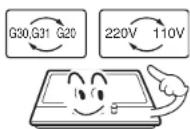
- Gas Conversion 24
- Burner Features 25

natural_image
Blank gray image with no visible content, text, or symbolsPreface
Thank you for using our appliance.
To use this appliance correctly and prevent any potential risk, read these instructions before use the appliance.
Keep these instructions at the place where you can find it easily.
If you are unsure of any of the information contained in these instructions, please contact the SamSung customer care center.
These instructions are only valid for the countries of destination, the identification symbols of which are indicated on the cover of the instruction manual.
The manufacturer shall not be held responsible for any damages to persons or property caused by incorrect installation or use of the appliance.
The appliance has been certified for use in countries other than those stated on the appliance.
The manufacturer also reserves the right to make any modifications to the products as may be considered necessary or useful, also in the interests of the user, without jeopardizing the main functional and safety features of the products themselves.
Safety Warning
■ Your safety is of the utmost importance to SamSung.
■ You must read warnings carefully before installing or using the appliance.
■ This instruction booklet must be kept with the appliance for any future reference. If the appliance is sold or transferred to another person, ensure the booklet is passed on to the new user.
■ The manufacturer declines any liability should these safety measures not be observed.
■ The following marks are made to be easily understood so that you can prevent any safety accident caused by misuse in advance and use the appliance more conveniently.
■ Completely understand the following contents before read the instruction.

Danger/Warning
If this mark is neglected, the user may be dead or seriously injured.

Caution
If this mark is neglected, the user may be injured or damaged in property.
■ The following marks mean as follow:

General Danger, Warning and Caution

ccess
No Fire Tool
Must D


Danger
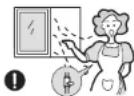
■ If gas seems to leak, take the actions as follow :
- Do not turn on the light.
- Do not switch on/off any electrical appliance and do not touch any electric plug.
- Do not use a telephone.
[1] Stop using the product and close the middle valve.
② Open the window to ventilate.
3 Contact our service center by using a phone outside.
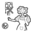


* The fuel gas contains mercaptan, so that you can feel that the gas leaks even where only 1/1000 of the gas exists in the air with specific smell (smell of rotten garlic or egg).
Installation

Warning
■ This appliance shall be installed in accordance with regulations in force and only used in a well ventilated space.
■ Prior to installation, ensure that the gas and electrical supply complies with the type stated on the rating plate.
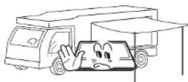
■ Do not install this appliance on any type of marine vessel or Leisure Accommodation Vehicle.
■ The gas pipe and electrical cable must be installed in such a way that they do not touch any parts or the appliance.


Caution
■ This appliance should be installed by a qualified technician or installer.
■ The adjustment conditions for this appliance are stated on the label or data plate.
■ After unpacking the appliance, make sure the product is not damaged and that the connection cord is in perfect condition. Otherwise, contact the dealer before installing the appliance.
■ The adjacent furniture and all materials used in the installation must be able to withstand a minimum temperature of 85^ C above the ambient temperature of the room it is located in, whilst in use.
■ Remove all packaging before using the appliance.
Child and People Safety

Warning
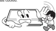
■ Do not allow children to play near or with the appliance. The appliance gets hot when it is in use. Children should be kept away until it has cooled.

Caution
■ This appliance is designed to be operated by adults.
■ Children can also injure themselves by pulling pans or pots off the appliance.
This appliance is not intended for use by children or other persons whose physical, sensory or mental capabilities or lack of experience and knowledge prevents them from using the appliance safety without supervision or instruction by a responsible person to ensure that they can use the appliance safety.
During Use

Warning
■ Only use the appliance for preparing food. Never use it as a heater.
■ It is dangerous to modify or try to modify the characteristics of this appliance.
■ The use of a gas cooking appliance results in the production of heat and moisture in the room in which it is installed. Ensure that the kitchen is well ventilated: keep natural ventilation holes open or install a mechanical ventilation device (mechanical extractor hood).

■ Do not use this appliance if it is in contact with water. Do not operate this appliance with wet hands.

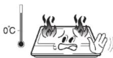
■ The heating and cooking surfaces of the appliance become hot when they are in use, take all due precautions.

■ Do not use large cloths, tea towels or similar as the ends could touch the flames and catch fire.
■ Never leave the appliance unattended when cooking with oil and fats. If fat and oil overheats, then it can ignite extremely quickly.

■ Unstable or misshapen pans should not be used on the hob as unstable pans can cause an accident by tipping or spillage.

During Use (Continued)
■ Do not place any flammable object near the appliance.
■ Perishable food, plastic items and aerosols may be affected by heat and should not stored above or below the appliance.

■ Do not spray aerosols in the vicinity of this appliance while it is in operaiton.
■ Ensure the control knobs are in the 'OFF' position when not in use.

Caution
■ This appliance is intended for domestic cooking only. It is not designed for commercial or industrial purpose
■ Prolonged intensive use of the appliance may call for additional ventilation, for example opening of a window, or increasing the level of mechanical ventilation where present.
■ Use heat-resistant pot holders or gloves when handing hot pots and pans.
■ Take care not to let pot holders or gloves get damp or wet, as this causes heat to transfer through the material quicker with the risk of burning yourself.
■ Only ever use the burners after placing pots and pans on them. Do not heat up any empty pots or pans.
■ Never use plastic or aluminium foil dishes on the appliance.
■ When using other electrical appliances, ensure the cable does not come into contact with the appliance surfaces of the cooking appliance.
■ If you have any mechanical substance such as artificial heart and etc in your body, consult with a doctor before using the appliance.
Cleaning & Service

Warning
■ Never use abrasive or caustic cleaning agents.
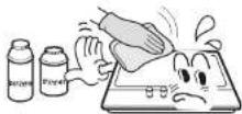
■ This appliance should only be repaired or serviced by an authorised Service Engineer and only genuine approved spare parts should be used.

Caution
■ Before attempting to clean the appliance, it should be disconnected from the mains and cool.
- You should not use a steam jet or any other high pressure cleaning equipment to clean the appliance.
Environmental Information
■ After installation, please dispose of the packaging with due regard to safety and the environment.
■ When disposing of an old appliance, make it unusable, by cutting off the cable.

Correct Disposal of This Product (Waste Electrical & Electronic Eq
This marking shown on the product or its literature, indicates that it should not be disposed with other household wastes at the end of its working life. To prevent possible harm to the environment or human health from uncontrolled waste disposal, please separate this from other types of wastes and recycle it responsibly to promote the sustainable reuse of material resources.
■ Household users should contact either the retailer where they purchased this product, or their local government office, for details of where and how they can take this item for environmentally safe recycling.
■ Business users should contact their supplier and check the terms and conditions of the purchase contract. This product should not be mixed with other commercial wastes for disposal.
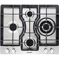
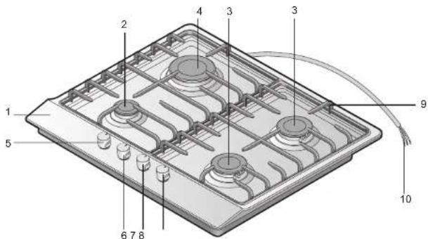
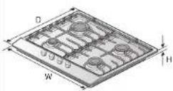
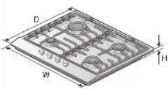
Description of the appliance
text_image
1 2 3 4 5 6 7 8 9 10- Top Plate
- Auxiliary Burner
- Semi-rapid Bumer
- Rapid Burner
- Control handle for rear left burner (Rapid burner)
-
Control handle for front left burner (Auxiliary burner)
-
Control handle for front right burner (Semi-rapid burner)
- Control handle for rear right burner (Semi-rapid burner)
- Pan support
- Connection Cord
Handle
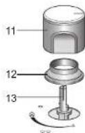
- Control handle
- Sealing ring
- Tap
Burner
(Auxiliary, Semi-rapid and Rapid)
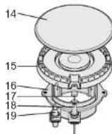
- Burner lid
- Flame Spreader
- Burner Cup
- Injector
- Ignition Electrode
- Flame supervision device
How to Use the Appliance
Turn on
Preparation
The following symbols will appear on the control panel, next to each control handle :
| Circle: gas off | Small flame: minimum setting | ||
| Large flame: maximum setting | Ignition position |
■ The minimum setting is at the end of the anti-clockwise rotation of the control handle.
■ All operation positions must be selected between the maximum and minimum position.
■ The symbol on the control panel, next to the control handle will indicate which burner it operates.

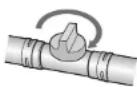
Ignition & Adjustment
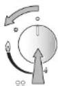
■ Open the middle valve.
■ Place a pot or a pan on the corresponding cooking position.
■ Fully press down the control handle for the corresponding cooking position and turn it to the left, to the ignition position, and hold it there for a few seconds at most until the burner ignites.
■ After igniting, keep the control handle pressed for about 5\~8 seconds more because the heat sensor that opens the gas channel has to warm up first. And set control handle to the position you want.
■ If the burner does not light, repeat the process.
The flame size can be set continuously between maximum and minimum by slowing turning the control handle.

■ If the Igniters are dirty, this makes the burner harder to light, so you should keep them as clean as possible. Do this with a small brush and make sure that the ignition device is not hit or knocked violently.
■ The flame supervision device shall not be operated for more than 15s. If after 15s the burner has not lit, stop operating the device and open the compartment door and/or wait at least 1min before attempting a further ignition of the burner.
How to Use the Appliance (Continued)
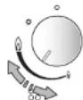
Turn off

Extinguishment

○○
○○
■ Turn the control handle to clockwise, to setting 'O' (off position)
■ Close the middle valve.

■ Right after extinguishment, the appliance is still hot. Be careful not to be burned.

■ This appliance is fitted with a Flame supervision device which cuts off the supply of gas to a burner if the flame goes out, for example if food has boiled over, or if there was a sudden draught.
In the event of the burner flames being accidentally extinguished, turn off the burner control and do not attempt to re-ignite the burner for at least 1min.
Safety and Energy saving advice
- The diameter of the bottom of the pan should correspond to that of the burner.
| BURNERS | PANS | |
| min. max. | ||
| Rapid 200mm 260mm | ||
| Semi-Rapid 130mm 180mm | ||
| Auxiliary 100mm 120mm | ||

- User can't use cooking pan on the hotplate that overlap its edge.
| NO YES | |||
 | Do not use small diameter cookware on large burners.The flame should never come up the sides of the cookware. | Always use cookware that are suitable for each burner, so as to avoid wasting gas and discolouring the cookware. |  |
 | Never cook without a lid or with the lid half off- you are wasting energy. | Always place the lid on the cookware. |  |
 | Do not use a pan with a convex or concave bottom. | Only use pots, saucepans and frying pans with thick, flat bottom. |  |
 | Do not place cookware on one side of a burner, as if could tip over. Do not use cookware with a large diameter on the burners near the controls, which when placed on the middle of the burner may touch the controls or be so close to them that they increase the temperature in this area and may cause damage. | Always place the cookware right over the burners, not to one side. |   |
 | Never place cookware directly on top of the burner. | Place the cookware on top of the pan support. | |
 | Do not use excessive weight and do not hit the hob with heavy objects. | Handle cookware carefully when they are on the burner. |  |

- It is not permitted to use roasting pans, frying pans or grill stones heated simultaneously by several burners because the resulting heat build-up may damage the appliance.
- Do not touch the hob top and pan support while using or for a certain period after using.

■ As soon as a liquid starts boiling, turn down the flame so that it will barely keep the liquid simmering.
Cleaning and Maintenance

■ Cleaning operations must only be carried out when the appliance is cool.
■ The appliance should be disconnected from your mains supply before commencing any cleaning process.
■ Clean the appliance regularly, preferably after each use.
■ Abrasive cleaners or sharp objects will damage the appliance surface; you should clean it using water and a little washing up liquid.
| Usable Unusable | |
| [HTT8] (2274) | (W374) (0258) |
| [7X6] (CW39) | (AC48) (AB27) (30C0) |
| Neutral Detergent | Abrasive Thinner/Benzend I |


Pan support, Control handles
■ Take off the pan supports.
■ Clean these and the control handles with a damp cloth, washing up liquid and warm water. Stubborn soiling is best soaked before.
■ Finally dry everything with a clean soft cloth.
Top plate
■ Regularly wipe over the top plate using a soft cloth well wrung out in warm water to which a little washing up liquid has been added.
■ Dry the top plate thoroughly after cleaning.
■ Thoroughly remove salty foods or liquids from the hob as soon as possible to avoid the risk of corrosion.
■ Stainless steel parts of the appliance may become discoloured over time. This is normal because of the high temperatures. Each time the appliance is used these parts should be cleaned with a product that is suitable for stainless steel.
Cleaning and Maintenance (Continued)
BURNERS
■ Remove the burner lids and Flame Spreaders by pulling them upwards and away from the top plate.
■ Soak them in hot water and a little detergent.
■ After cleaning and washing them, wipe and dry them carefully. Make sure that the flame holes are clean and completely dry.
■ Wipe the fixed parts of the burner cup with a damp cloth and dry afterwards.
■ Gently wipe the ignition device and flame supervision device with a well wrung-out cloth and wipe dry with a clean cloth.
■ Before placing the burners back on the top plate, make sure that the injector is not blocked.
■ Re-assemble the Auxiliary, Semi-Rapid and Rapid burners as follows :
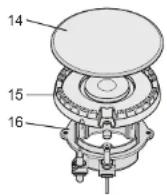
- Place the flame spreader (15) on to the burner cup (16) so that the ignition device and the flame supervision device extend through their respective holes in the flame spreader. The flame spreader must click into place correctly.
- Replace the burner lid (14) ensuring that the locating tabs fit into the noches in the flame spreader (15).

Replace parts in the correct order after cleaning.
- Do not mix up the top and bottom.
- The locating lugs must fit exactly into the notches.
Troubleshooting
■ Repairs to the gas and electrical components of this appliance must only be carried out by a suitably qualified and competent person to ensure safety.
■ However, some minor problems can be resolved as follows :
| Problem Probable cause Solution | ||
| Not ignited | No Spark. Check the electricity supply | |
| The burner lid is badly assembled. Assemble the lid correctly. | ||
| The middle valve is closed. Open the middle valve completely. | ||
| Badly ignited | The middle valve is incompletely opened. | Open the middle valve completely. |
| The burner lid is badly assembled. Assemble the lid correctly. | ||
| The ignition plug is contaminated with alien substance. | Wipe such alien substance with dried clothing. | |
| The burners are wet. Dry the burners lids carefully. | ||
| The holes in the flame spreader are clogged. | Clean the flame spreader. | |
| Noise made when combusted and ignited | The burner lid is badly assembled. Assemble the burner lid correctly. | |
| Fire off while using | The flame supervision device is contaminated with alien substance. | Clean the flame supervision device. |
| Yellow Flame | The holes in the flame spreader are clogged. | Clean the flame spreader. |
| Different gas is used. Check the gas used. | ||
| Unstable Flame | The burner lid is badly assembled. Assemble the burner lid correctly. | |
| Gas Smell | A gas tap has been left on. | Check to see if any gas taps are on. |
| There may be a leak between the coupling and the gas bottle. | Make sure that the connection is airtight. | |

■ If problem is not solved, please contact the SamSung customer care center.
Application for Service
If you have any comments or questions regarding a Samsung products, contact the SAMSUNG customer care center.
| Region | Country | Customer Care Center (TEL) | Web Site FAX no. | Address Remark | |
| Europe | BELGIUM | 02 201 2418 | www.samsung.be | N/A | Samsung Electronics Benelux B.V.Metallahan 50, 1800 Vilwonde, Belgium |
| CZECH REPUBLIC | 844 000 844 | www.samsung.com/z | N/A | Distributur pro Ceskau republiku, Samsung Ziří, česká organizaczní služka Vykskoviča 4, 14000 Praha 4 | |
| DENMARK | 70 70 19 70 | www.samsung.com/dk | N/A | Samsung Electronics Nordic ABSE -19427 Kanalipven 10A, Uplands Visby, Sweden | |
| FINLAND | 030-8227 515 | www.samsung.com/l | N/A | Samsung Electronics Nordic ABSE -19427 Kanalipven 10A, Uplands Visby, Sweden | |
| FRANCE | 3280 SAMSUNG or 08 25 08 66 85 € 0,15(Min) | www.samsung.com/ir | 01 4863 06 36 38 | Samsung Service Consarmatisurs88 rue des Verasses BP 50118 -Vilginiše -95950 ROISSY edex, France | |
| GERMANY | 01805 - 121213(€ 0,14(Min) | www.samsung.de | 01805 - 121214 | Samsung Electronics GmbHSamsung House, Am Kranberger Hang 6, 65824Schwalbach's, Deutschland | |
| HUNGARY | 08-40-SAMSUNG(7287664) | www.samsung.com/u | N/A | Samsung Electronics Nagyar Rd.Szvýdějce Busas Paris, 1007 Budapest, Szovágiat 05 37 | |
| ITALIA | 800-SAMSUNG(7287664) | www.samsung.com/lt | 0292141801 | Samsung Electronics Italia S.p.AVia C. Donat Cartin, 5, 20083, Camusco Sul Navoglc (MI) | |
| LUXEMBURG | 02 281 03 710 | www.samsung.u | N/A | Samsung Electronics Benelux B.V.Medallahan 50, 1800 Vilwonde,Belgium | |
| METHERLAND | 3800 20 200 88(€ 0,10(Min) | www.samsung.nl | N/A | Samsung Electronics Benelux B.VPostcus 981 2000AR Delft Nederland | |
| NORWAY | 815 56 430 | www.samsung.com/n/o | N/A | Samsung Electronics Nordic ABSE -19427 Kanalipven 10A, Uplands Visby, Sweden | |
| POLAND | 0 601 BC1 881 | www.samsung.com/jl | +48 22807 4448 | Samsung Electronics Polska sp. Z o.o.Draf Oblujki Kierlao2-678 Warszawa, ul. Šularimova 2a | |
| PORTUGAL | 80 B 200 128 | www.samsung.com/jl | N/A | SAMSUNG ELECTRONICA PORTUGUESA, S.ARua Cesario Verde, no 5-4, Paz2795-753 Qasiyas-Portugal | |
| SLOVAKA | 0800-SAMSUNG(728766) | www.samsung.com/x | N/A | N/A | |
| SPAIN | 902 10 11 30 | www.samsung.com/s | N/A | SAMSUNG ELECTRONICS IFERIA, S.A.Clences, 55-69 (Polígono Pedrosa)08008 HOSPITALET DE LLOBREGAT (Barcelona) | |
| SWEDEN | 0771 430 200 | www.samsung.com/s | N/A | Samsung Electronics Nordic ABSE -19427 Kanalipven 10A, Uplands Visby, Sweden | |
| U.K. | 0870 SAMSUNG(7287664) | www.samsung.com/uk | 08707221127 | Samsung Electronics U.K. Ltd. Customer Care Centre POBox 17243 Edinburgh, EH11 4YB United Kingdom | |
| Republic of Ireland | 0818 717 100 | www.samsung.com/uk | +44 038707221127 | ||
| Switzerland | 0800-SAMSUNG(7287664) | http://www.samsung.com/ce | N/A | ||
| CIS | RUSSIA | 8-800-200-0430 | www.samsung.ru | +7-495-783-1556 | 117545 Roszav, Moscow, ул. Дерожная, д.3, repr. 8 |
| KAZAVISTAN | 8-800-080-1189 | www.samsung.cz | +7 (3272)58 59-66 | 050051 4th floor, 172 Destly Ave. Almaty Republic of Kazakhstan | |
| UZEBKISTAN | 8-800-120-0430 | www.samsung.uz | +698-71-120-7206 | 103-742 129, International Business Center, 107B AmirTenur stl., Taftiewd, Uzbekistan | |
| UKRAINE | 8-800-502-0000 | www.samsung.com/ur | +380 (44)557 59 48 | 30A, Speeka St. Floor 3, Klaw 04070, Ukraine | |
| LITHUANIA | 8-800-77777 | www.samsung.lt | +370 52139 770 | Zemates 21, Vilnius, LT 2038, Lithuania | |
| LATIVA | 800-7267 | http://www.samsung.com/index.htm | +371 750 84 80 | J. Aunana 2. Riga, LV-1340, Latvia | |
| ESTONA | 800-7267 | www.samsung.se | |||
| Asia Pacific | AUSTRALIA | 1300 362 803 | www.samsung.com/u | (612)9763 5750 | Samsung Electronics Australia/Parityview Drive, Homebush Bay NSW 2127 |
| MALAYSIA | 1800-89-9999 | www.samsung.com/ry | 03.22636758 | Samsung Malaysia Electronics Sdn. Bhd.38-1-1, Level 1, Block 3B, Plaza Sentral, Jalan SteenSentral S, Kl. Sentral, 50479, Kuala Lumpur, Malaysia | |
| THAILAND | 1800-29-323202-888 3232 | www.samsung.com/rl | 02-589 3288 | Thai Samsung Electronics Co., Ltd. Service Department1,8 floor Bosmini Building 138 Silom Rd., SanyawongBangkok Bangkok 10000they: Inserghenyakai, Mumbai 656alet 138, Siamnagaros de 1,6 mankoulu#or##s####, namn##s####, nama##s####, nama##s####, nama##s####, nama##s####, nama##s####, nama##s####, nama##s####, nama##s####, nama##s####, nama##s####, nama##s####, nama##s####, nama##s####, nama##s####, nama##s####, nama##s####, nama##s#### |
Technical instructions

■ This appliance must be installed by a qualified technician or installer.
■ Prior to installation, ensure that the local distribution conditions (nature of the gas and gas pressure) and the adjustment of the appliance are compatible.
■ The adjustment conditions for this appliance are stated on the label (or data plate).
This appliance is not connected to a combustion products evacuation device. It shall be installed and connected in accordance with current installation regulations. Particular attention shall be given to the relevant requirements regarding ventilaton.
■ Before installing, turn off the gas and electricity supply to the appliance.
■ All appliances containing any electrical components must be earthed.
■ Ensure that the gas pipe and electrical cable are installed in such a way that they do not touch any parts of the appliacne which become hot.
■ Gas pipe or connector shouldn't be bent or blocked by any other appliances.
- Check the dimensions of the appliance as well as the dimensions of the gap to be cut in the kitchen unit.
■ The panels located above the work surface, directly next to the appliance, must be made of non-flammable material. Both the stratified surfacing and the glue used to secure it should be heat resistant, to prevent deterioration.
■ Turn on appliance tap and light each burners.
Check for a clear blue flame without yellow tipping.
If burners shows any abnormalities check the following :
- Burner lid on correctly
- Flame spreader positioned correctly
- Burner vertically aligned with injector nipple
■ A full operational test and a test for possible leakages must be carried out by the fitter after installation.
■ The flexible tube shall be fitted in such a way that it cannot come into contact with a moveable part of the housing unit and does not pass through any space susceptible of becoming congested.
Engineers technical data
Appliance Specification
 |  | |||
| Model GN641FFXD GN641FFB D GN642FFXD GN642FFBD | ||||
| Pan Support | Drawing Cast Iron | |||
| Top Plate | Stainless steel Enamel coating Stainless steel Enamel coating | |||
| Control Handle | Silver color Titan color Silver color | Titan color | ||
| Weight | 9.5kg 9.5kg | 1kg 1kg | ||
| Dimension (WxDxH) | 594*510*50 | 594*510*50 | ||
| Ignition device | Continuous Ignition Type | |||
| Gas Connection | 1/2 inch female thread | |||
| Electric supply | 220~240V, 50/60Hz | |||
| Burner Feature | Rapid (1EA), Semi-rapid (2EA), Auxiliary (1EA) | |||
○ APPLIANCE CLASS : Class 3
○ APPLIANCE CATEGORY :
| BE/FR | GB/IT/PT/LT | PL | |
| Cat. | II 2E+3+ | II 2II3+ | II 2E3B/P |
| P(mbar) | 20-25 - 28-30/37 | 20 - 28-30/37 | 20-36 |
| HU | |||
| Cat. | II 2II3B/P | ||
| P(mbar) | 25-30 |
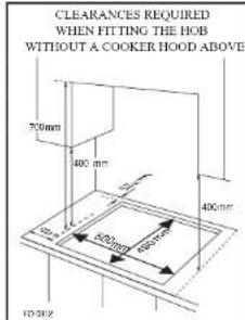
Positioning
text_image
CLEARANCES REQUIRED WHEN FITTING THE HOB WITHOUT A COOKER HOOD ABOVE 700mm 400 mm 500mm 600mm 400mm FD 2012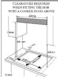
text_image
CLEARANCES REQUIRED WHEN FITTING THE HOB WITH A COOKER HOOD ABOVE 600mm 700mm 400 mm 400mm 400mm 800mm 800mm FC-0019Cut out size
Width: 560mm
Depth:490mm
Thickness:30\~50mm
■ This appliance is to be built into a kitchen unit or 600mm worktop, providing the following minimum distances are allowed;
- The edge of the appliance must be a minimum distance of 55mm from a rear wall.
- A minimum distance of 100mm must be left between the side edges of the appliance and any adjacent cabinets or walls.
- The minimum distance combustible material can be fitted above the appliance in line with the edges of the appliance is 400mm. If it is fitted below 400mm a space of 50mm must be allowed from the edges of the appliance.
- The minimum distance combustible material can be fitted directly above the appliance is 700mm.
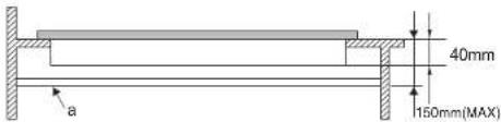
text_image
40mm 150mm(MAX) a- This panel(a) must be positioned at a maximum distance of 150mm below the worktop.
Installing the appliance
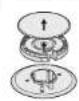
natural_image
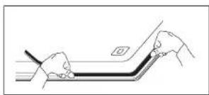
Line drawing of two hands holding a tool, interacting with a curved object (no text or symbols)- Remove the pan support, the burner lid and flame spreader and carefully turn the appliance upside down and place it on a cushioned mat.
Take care that the ignition devices and flame supervision devices are not damaged in this operation. - Apply the sealing strip provided around the edge of the appliance.
- Do not leave a gap in the sealing agent or overlap the thickness.
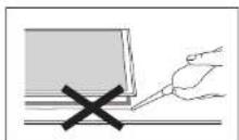

Do not use a silicon sealant to seal the appliance against the aperture.
This will make it difficult to remove the appliance from the aperture in future, particularly if it needs to be serviced.
text_image
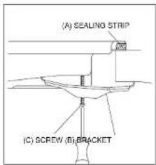
(A) SEALING STRIP (C) SCREW (B) BRACKET- Place the bracket(B) over the holes that match the size of the screws. There are one set of screw holes in each corner of the hob(H).
Slightly tighten a screw(C) through the bracket(B) so that the bracket is attached to the hob, but so that you can still adjust the position it. - Carefully turn the hob back over and then gently lower it into the aperture hole that you have cut out.
- On the underneath of the hob, adjust the brackets into a position that is suitable for your worktop. Then fully tighten the screws(C) to secure the hob into position.
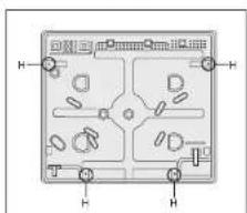
text_image
H H H HGas Connection

■ This appliance must be installed and connected in accordance with installation regulations in force in the country in which the appliance is to be used.
■ This appliance is supplied to run on natural gas only and cannot be used on any other type of gas without modification.
Conversion for use on LPG and other gases must only be undertaken by a qualified person.
The gas inlet connection fitting is 1/2 inch female thread.
Gas distributed by pipe ; natural gas, propane-air gas or butane-air gas
For your safety, you must choose from the three following connection option
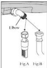
■ Connection with a rigid pipe made from copper and with screw-on mechanical connectors.
Make the connection directly to the end of the elbow fitted on the appliance.
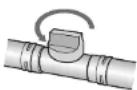
■ Connection using flexible undulated metal tube with screw-on connectors. (Fig. A)
You can use a flexible stainless steel pipe available from your after sales service department.
■ Connection using flexible tube with screw-on connectors. (Fig.B)
These tubes must not exceed 2 meters in length and must be accessible along their entire length.
Gas supplied by tank or cylinder (butane/propane)
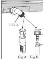
- For the user's safety, we advise the connection to be made with a rigid pipe if this is possible, using a flexible undulated metal tube with screw-on connectors (maximum length 2 meters) (Fig.A)
For an existing installation, where it is not possible to fit a reinforced, braided, flexible gas hose, the connection can be made with a flexible gas hose (maximum length 2 meters), with two clamps. One on the connector, and the other on the pressure regulator, and a gasket should be fitted between the connector and the hob's elbow. (Fig.B)

■ You can obtain the connector and the gasket from your After-Sales Service. In France, you must use a tube or a pipe featuring the "NF Gaz" logo. If the Installation is difficult, unscrew the Elbow slightly and tighten it after locating the Elbow.

- A full operational test and a test for possible leakages must be carried out by the fitter after installation. (such as soap water or gas detector) - Access to the whole length of the connection hose must be possible and the gas hose must be replaced before its use before the end of service life (indicated on the hose)
Electrical Connection
■ This appliance must be earthed.
■ This appliance is designed to be connected to a 220\~240V, 50/60Hz AC electricity supply.
■ The wires in the mains lead are coloured in accordance with the following code ;
- Green/yellow = Earth
- Blue = Neutral
- Brown = Live

■ The wire which is coloured green and yellow must be connected to the terminal which is marked with the letter E or by the earth symbol.

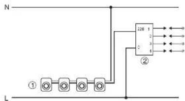
text_image
N ① ② 220 1 3 4 5 6 7 8 9 L- MICRO SWITCHES
- IGNITER
Gas Conversion

■ Be careful, the operations and adjustments to be carried out when converting
from one gas to another.
■ All work must be carried out by a qualified technician.
■ Before you begin, turn off the gas and electricity supply to the appliance.

Change the injector of the burners.
Remove the pan support. Burner lid and Flame spreader.
Unscrew the injector using a 7mm box spanner and replace it with the stipulated injector for new gas supply. (see table 1. Page 25.) Carefully reassemble the all components.
After injectors are replaced, it is advisable to strongly tighten the injector in place.

Adjusting of the taps of the cooking hob burners for reduced consumption

① Turn the taps down to minimum.
② Remove the control handles from taps.
① Adjusting the by-pass screw.
- For converting G20 into G30 or G31, the screw must be screwed down fully tight.
- At this stage, light up the burners and turn the
control handles from max position to minimum position to check flame stability. - For converting G30 or G31 into G20, please contact
"After-Sales Service".
④ Replace the control handles on the taps.

■ Do not dismantle the tap shaft: in the event of a malfunction, change the whole tap.
■ Before placing the burners back on the top place, make sure that the injector is
not blocked.
■ A full operational test and a test for possible leakages must be carried out after
gas conversion. (such as soap water or gas detector)
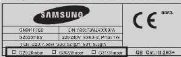
■ After completing conversion, a qualified technician or installer has to mark "V"
on the right gas category
to match with the setting
in rating plate.
Remove the previous
setting "V" mark
text_image
SAMSUNG GN8411FBC 5N: 03079M24000X G2520mbar 229-240V 50/00 - 2. Pmax 1W ΣQn G29 7,5kV 33C 921gm G31 033gm □ G29-20mbar □ G38-20mbar □ G31-20mbar CE GB Cal., II 2H3+Burner Features
Nominal heat input and flow rates see below at 15°C at 1,013 mbar. (Table 1)
| COUN-TRY | TYPE OF GAS | BURNER Rapid Semi-rapid Auxiliary | Total | ||||||
| POSITION Max | Min Max | Min Max Min | |||||||
| GB,IT FR,HU BE,LT NL,PT ES,CZ SK | G-30 BUTANE 29 mbar | Injector make (1/100 mm) | 85 65 50 | - | |||||
| Nominal heat input (Kw) | 3.0 0 | 78 1.75 | 0.49 1.0 | 0.4 | 7.5 | ||||
| Nominal flow rates (g/h) | 216 53 | 125 33 | 74 | 28 | |||||
| PL | G-30 BUTANE 37 mbar | Injector make (1/100 mm) | 80 62 47 | - | |||||
| Nominal heat input (Kw) | 3.0 0 | 88 1.75 | 0.52 1.0 | 0.42 | 7.5 | ||||
| Nominal flow rates (g/h) | 216 61 | 127 36 | 71 | 28 | |||||
| GB,IT FR,BE LT,PT ES,CZ SK | G-31 PROPANE 37 mbar | Injector make (1/100 mm) | 85 65 50 | - | |||||
| Nominal heat input (Kw) | 3.0 0 | 77 1.75 | 0.47 1.0 | 0.39 | 7.5 | ||||
| Nominal flow rates (g/h) | 211 | 51 123 | 32 70 | 27 | |||||
| GB,IT FR,BE LT,PT PL,ES CZ,SK | G-20 NATURAL 20 mbar | Injector make (1/100 mm) | 119 | 97 72 - | |||||
| Nominal heat rating (Kw) | 3.0 0 | 69 1.75 | 0.55 1.0 | 0.38 | 7.5 | ||||
| Nominal flow rating (U/h) | 286 64 | 168 52 | 96 | 36 | |||||
| HU | G-20 NATURAL 25 mbar | Injector make (1/100 mm) | 110 | 91 68 - | |||||
| Nominal heat input (Kw) | 3.0 0 | 78 1.75 | 0.6 1.0 | 0.43 | 7.5 | ||||
| Nominal flow rates (U/h) | 285 71 | 167 57 | 95 | 39 | |||||
| Burner | Calibrated orifice 1/100mm |
| Auxiliary | 31 |
| Semi-rapid | 34 |
| Rapid | 43 |
- Aeration adjustment none
MEMO
GB
SAMSUNG
Instructions techniques 18-25
Instructions techniques