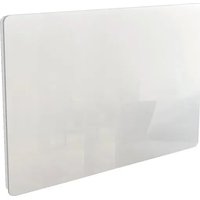
BAT-HT15HB - Electric heater Kalia - Free user manual and instructions
Find the device manual for free BAT-HT15HB Kalia in PDF.


User questions about BAT-HT15HB Kalia
0 question about this device. Answer the ones you know or ask your own.
Ask a new question about this device
Download the instructions for your Electric heater in PDF format for free! Find your manual BAT-HT15HB - Kalia and take your electronic device back in hand. On this page are published all the documents necessary for the use of your device. BAT-HT15HB by Kalia.
USER MANUAL BAT-HT15HB Kalia
natural_image
Line drawing of a rectangular electronic device with a side panel (no text or symbols)POUR USAGE A L'INTERIEUR FOR INDOOR USE
IMPORTÉ PAR BATIMEX:
VERSION DE JUIN 2023
natural_image
Technical diagram of a mechanical assembly with no visible text or symbolstext_image
Technical diagram showing a mechanical setup with a vertical rod and a circular component, labeled with points A and a directional arrow.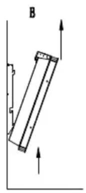
natural_image
Simple line drawing of a rectangular object with arrows indicating direction, no text or symbols present.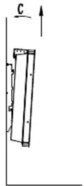
natural_image
Simple line drawing of a vertical panel with an upward arrow labeled 'C' (no text or symbols beyond the label)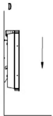
text_image
D G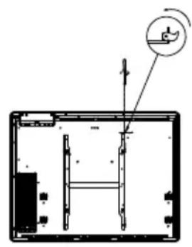
natural_image
Technical line drawing of a mechanical assembly with no visible text or symbolstext_image
1 12:00 P * Ⓛ | |Before using this device for the first time, please read these instructions carefully and keep them in a safe place for future reference.
SAFETY INSTRUCTIONS
The heater must not be used if the glass panels are damaged.
CAUTION: Basic safety precautions should always be followed when using an electrical appliance, including the following precautions, to reduce the risk of fire, electric shock or injury.
This device can be used by children aged at least 8 years and by people with reduced physical, sensory or mental capacities or without experience or knowledge, if they are properly supervised. s or if instructions relating to the use of the appliance in complete safety have been given to them and if the risks involved have been apprehended. Children should not play with the device. Cleaning and user maintenance shall not be carried out by children without supervision. Children between the ages of 3 and 8 years should only switch the appliance on or off, provided that the appliance has been placed or installed in its normal intended position and that these children are supervised or have received instructions on how to use the appliance safely and fully understand the potential dangers. Children between the ages of 3 and 8 should not plug in, adjust, clean the appliance, or perform user maintenance.
CAUTION: The heater should not be used if the glass panels are damaged..
CAUTION: Young children should not lean on the hot surface of the appliance as parts of this product can become very hot and cause burns. Children under 3 years of age should be kept away unless they are under continuous supervision.
For household and indoor use only. The heater should not be placed directly below an electrical outlet.
Do not use the heater if the cord is damaged.
If the cable or flexible outer cord of this fixture is damaged, it should be replaced only by the manufacturer or its service agent or a person of equivalent qualification, to avoid risk.

WARNING: To avoid overheating, do not cover the heater.

CAUTION - Parts of this product can become very hot and cause Special care should be taken in the presence of children and other
To isolate the unit from the power supply, turn the unit off, then make sure all poles are disconnected. A means of disconnection with a contact opening distance of all poles must be provided in the fixed conduits in accordance with the installation rules.
CAUTION: To avoid hazards due to inadvertent resetting of the thermal cutout, this unit must not be powered through an external switch, such as a timer, or be connected to a circuit that is regularly turned on and off by the power supplier.
Do not insert or allow foreign objects to enter any ventilation or exhaust opening as this will result in electrical shock or fire and damage to the unit.
Information requirements for electric decentralized heaters:
| Model Number: BAT-HT10HB | |||||
| Characteristic Symbol Value Unit Characteristic Unit | |||||
| Heat output Type of heat supply, for electric decentralized storage heaters only (select one type only) | |||||
| Nominal thermal output | P_nom | 1 kW m | manual th | thermal control of the load with integrated thermostat | [no] |
| Minimum thermal output (indicative) | P_min | N/A kW | manual | thermal control of the load with information on the temperature of the room and/or outside | [no] |
| Maximum continuous thermal output | P_max,c | 1 kW e | electronic | thermal control of the load with reception of information on the temperature of the room and/or outside | [no] |
| Auxiliary power consumption | fan-controllable thermal output | [no] | |||
| At rated heat output | eI_max | 0.000 kW | Type | of heat output/room temperature control (select one type only) | |
| At minimum heat output | eI_min | 0.000 kW | single | stage heat output control, no room temperature control | [no] |
| In standby mode | eI_SB | 0.00017 | kW two | or more manual steps, no room temperature control | [no] |
| room temperature control with mechanical thermostat | [no] | |
| electronic room temperature control | [no] | |
| electronic room temperature control with daily programmer | [no] | |
| electronic room temperature control with weekly programmer | [yes] | |
| Other control options (select one or more) | ||
| room temperature control, with presence sensor | [no] | |
| room temperature control with open window sensor | [yes] | |
| remote control option [no] | ||
| adaptive activation control [no] | ||
| activation time limitation [no] | ||
| black globe sensor [no] | ||
| Contact details B | ATIMEX SAS112 Rue Ampère 13830 Roquefort-la-Bédoule France | |
| Model Number: BAT-HT15HB | |||||
| Characteristic Symbol Value Unit Characteristic Unit | |||||
| Heat output Type of heat supply, for electric decentralized storage heaters only (select one type only) | |||||
| Nominal thermal output | P_nom | 1,5 kW | manual | thermal control of the load with integrated thermostat | [no] |
| Minimum thermal output (indicative) | P_min | N/A kW | manual | thermal control of the load with information on the temperature of the room and/or outside | [no] |
| Maximum continuous thermal output | P_max,c | 1,5 kW | electronic thermal control of the load with reception of information on the temperature of the room and/or outside | [no] |
| Auxiliary power consumption fan-controllable thermal output | [no] | |||
| At rated heat output | eI_max | 0.000 kW | W Type of heat output/room temperature control (select one type only) | |
| At minimum heat output | eI_min | 0.000 kW | W single stage heat output control, no room temperature control | [no] |
| In standby mode | eI_SB | 0.00017 | kW two or more manual steps, no room temperature control | [no] |
| room temperature control with mechanical thermostat | ||||
| electronic room temperature control | ||||
| electronic room temperature control with daily programmer | ||||
| electronic room temperature control with weekly programmer | ||||
| Other control options (select one or more) | ||||
| room temperature control, with presence sensor | ||||
| room temperature control with open window sensor | ||||
| remote control option [no] | ||||
| adaptive activation control [no] | ||||
| activation time limitation [no] | ||||
| black globe sensor [no] | ||||
| Contact details B | ATIMEX SAS 112 Rue Ampère 13830 Roquefort-la-Bédoule France | |||
| Model Number: BAT-HT20HB | |||||
| Characteristic Symbol Value Unit Characteristic Unit | |||||
| Heat output Type of heat supply, for electric decentralized storage heaters only (select one type only) | |||||
| Nominal thermal output | P_nom | 2 kW m | manual th | thermal control of the load with integrated thermostat | NA |
| Minimum thermal output (indicative) | P_min | N/A kW | manual | thermal control of the load with information on the temperature of the room and/or outside | NA |
| Maximum continuous thermal output | P_max,c | 2 kW e | electronic | thermal control of the load with reception of information on the temperature of the room and/or outside | NA |
| Auxiliary power consumption fan-controllable thermal output | NA | ||||
| At rated heat output | eI_max | 0.000 kW | Type | of heat output/room temperature control (select one type only) | |
| At minimum heat output | eI_min | 0.000 kW | single | stage heat output control, no room temperature control | [no] |
| In standby mode | eI_SB | 0.00017 | kW two | or more manual steps, no room temperature control | [no] |
| room temperature control with mechanical thermostat | [no] | ||||
| electronic room temperature control | [no] | ||||
| electronic room temperature control with daily programmer | [no] | ||||
| electronic room temperature control with weekly programmer | [yes] | ||||
| Other control options (select one or more) | |||||
| room temperature control, with presence sensor | [no] | ||
| room temperature control with open window sensor | [yes] | ||
| remote control option [no] | |||
| adaptive activation control [no] | |||
| activation time limitation [no] | |||
| black globe sensor [no] | |||
| Contact details B | ATIMEX SAS112 Rue Ampère 13830 Roquefort-la-Bédoule France | ||
INSTRUCTIONS REPLACEABLE COMPONENTS
If the power cable is damaged, it must be replaced by the manufacturer, its service department or similarly qualified persons in order to avoid a hazard.
INSTALLATION INSTRUCTIONS
The installation of the appliance in a bathroom is IMPERATIVELY carried out in volume 2 or out of volume in accordance with the NFC 15-100. The installation must be done by a qualified electrician to avoid any danger. The volumes illustrated in the NFC 15-100 standard are defined in relation to a bathtub or a shower tray, regardless of the room. Other appliances (washbasins, bidets, sinks and other water points) are not concerned.
1/ Determine the right location
Choose a suitable location for your heater, which must be firmly attached to the wall.
This appliance must never be used upside down, tilted or at 90^ . It must be mounted parallel to the wall (the wall must be vertical to the floor).
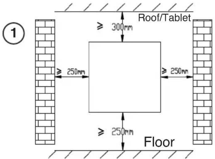
- Observe the minimum distances between the heater and walls, floor, furniture, curtains, etc. (as shown in Fig. 1).
- Do not install the unit in an air stream that could disturb its regulation.
- Do not place the unit near obstacles that restrict the air flow around it.
- Choose screws and plugs suitable for the wall material and the weight of the unit.
- Do not make any changes to the unit or its mounting bracket.
text_image
Roof/Tablet ≥ 300mm ≥ 250mm ≥ 250mm ≥ 250mm Floor ①Choose a suitable location for the heater (respect the minimum distances)
- Before installing the unit, check the condition of the wall to which it will be attached: the wall must be in good condition, it must not show any damage (cracks, sagging, moisture, ...).
Do not drill a hole near old holes, even if they have been filled in.
IMPORTANT! Make sure that there is no electrical wiring or any other installation (e.g. water pipe) near the locations where the holes will be drilled. Be sure to mount the unit vertically and firmly to the wall.
Drill the wall with a drill bit sized for the anchoring system. Remove debris and dust. Regularly check the unit's mounting points on the wall. Tighten them if necessary.
2/ Mounting
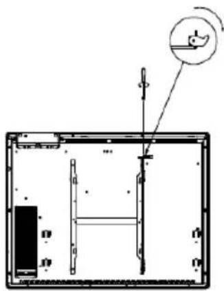
1-Loosen the mounting screw on the bracket without uns-crewing it completely. Slide the metal latch out of the hole. Remove the bracket by pulling it down.
natural_image
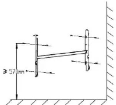
Technical line drawing of a mechanical assembly with no visible text or symbols2-Position the wall mount in the desired location. Use a spirit level to ensure that it is horizontal. Mark the location of the 4 screws to be used to fix the wall. Drill holes in the wall to attach the appropriate anchoring system. Attach the bracket to the wall.
text_image
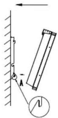
≥ 57 mm3-Place the radiator against its wall mounting bracket:
A: Position the heater so that its bottom holes line up with the hooks on the mounting bracket.
B: Push the heater down until the hooks snap into the holes.
C: Position the heater so that its top holes line up with the hooks on the mounting bracket.
D: Pull the heater down.
text_image
Diagram showing a mechanical setup with a pulley, rotating arm, and a hanging rod, labeled with angle A and length l.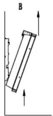
natural_image
Simple line drawing of a rectangular object with arrows indicating upward and downward motion, no text or symbols present.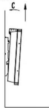
natural_image
Simple line drawing of a mechanical component with an upward force arrow labeled 'C' (no text or symbols beyond the label)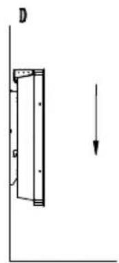
natural_image
Simple line drawing of a vertical panel with an arrow indicating downward motion (no text or symbols)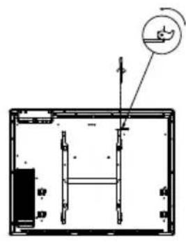
natural_image
Architectural floor plan showing room layout and structural elements (no text or labels)Slide the metal latch into the hole.
Tighten the screw to lock the radiator on the bracket.
3/ Electrical connection
Check that the mains voltage corresponds to that of the device. The appliance must be supplied through a residual current device (RCD) with a rated operating differential current not exceeding 30mA. The heater must be installed and connected to an installation in accordance with NF C 15-100 and by a qualified electrician.
The connection to the mains is made by the power cable via a connection box.
Supply voltage: 230V \~ single phase - 50 Hz.
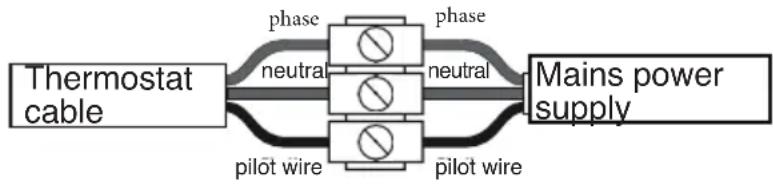
Before any intervention, cut off the power supply from the general electrical panel. Connect the two. Connect the wires of the power supply cable (Phase and Neutral) to a junction box. Make sure that the grey/blue wire is connected to the neutral and the brown/red wire to the phase. Check the tightness of the wires in the terminals of the wall connection box.
The black wire called «pilot wire» must be connected to the pilot wire of the installation.
Phase: brown / red
Neutral: grey / blue
Pilot wire: black
flowchart
graph LR
    A["Thermostat cable"] --> B["phase neutral"]
    B --> C["phase neutral"]
    C --> D["Mains power supply"]
    A --> E["pilot wire"]
    B --> F["pilot wire"]
    C --> G["pilot wire"]
Case 1: User electrical system without pilot wire: the pilot wire (black) must not be connected.
If your installation does not have a pilot wire, this wire must not be connected. Never use the ground wire of your installation (yellow-green color) to connect this pilot wire.
If there is no pilot wire, insulate the stripped end of the black wire to avoid any electrical contact with the other wires or the ground.
Case 2: User electrical system with pilot wire: connect the pilot wire (black) of the thermostat to the pilot wire (black) of your installation.
The pilot wire technology is used to centrally manage the electric heating system of a house.
The insulation of the installation's wiring must be protected by an insulating sleeve with an appropriate degree of protection.
INSTRUCTIONS FOR USE
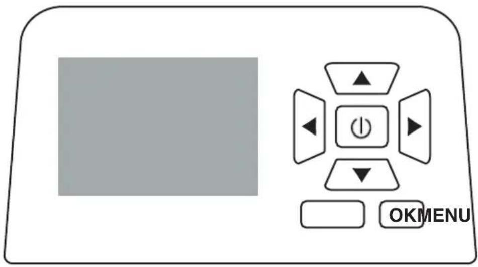
1/ Control panel
| Bouton | Fonction |
| [7x2c] | standby mode |
| MENU | Press briefly to display the setting menu: 1. Set the timer. 2. Set the program mode. 3. The window detection function Press for 3 sec. to activate/deactivate the keypad lock. |
| OK | Confirmation button |
 | In the operating status: change the operating mode (Comfort / ECO / Program or Pilot wire / Frost protection) In the setting status: change the options to the left or right. |
 | In the operating status: set the temperature. In the setting status: change the options up or down. |
text_image
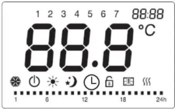
OKMENU2/ LCD screen
text_image
1 2 3 4 5 6 7 88:88 88.6 °C 1 6 12 18 24h| Symbol Function | |
| 1 | Standby mode (the unit does not operate but is switched on) |
| [2AH] | Frost protection mode (the unit maintains the room temperature at about 7°C) |
 | Comfort mode (setting the desired temperature) |
 | Eco mode (maintains the ECO temperature which is equal to the comfort temperature reduced by 3.5°C. This mode allows you to lower the temperature without changing the desired temperature in the comfort mode) |
 | Pilot mode (daily programs by pilot wire programmer) |
 | Keyboard lock |
 | Automatic open window detection function |
 | Heating indicator (when the unit is heating, this icon is displayed on the screen. The icon disappears when the detected temperature reaches the set temperature) |
 | Temperature (degree Celsius) |
| Weekly program setting | |
| Comfort mode on | |
| Eco mode on | |
3/ Operation
Press MENU to display the setting menu interface.
Press◀ /▶ or.▲/▼ to select 12:00 timer setting, Program mode Ⓛ setting or Window detection function. 📋. The selected icon will flash and the other icons will remain lit.
Press MENU to exit the setting menu or wait 30 seconds for the unit to automatically exit and return to the operating interface.
3.1/ Setting the time and day of the week
- Press MENU to enter the setting interface, and ◀ /▶ to select the time setting.
When the time display 12:00 flashes on the top right of the screen, press OK to start the time setting. Press ◀/▶ to toggle between day of the week, hours and minutes, and ▲/▼ to set the day of the week, hours and minutes.
- When the hour digit is flashing, press ▲/▼ to select the hour and press OK to confirm the hour setting and go to the minute setting from 00 to 59.
- When the minutes digit is flashing, press ▲ /▼ to select the minutes and press OK to confirm the minutes setting and go to the day setting. confirm the minute setting and move to the day of the week setting from 1 to 7.
- When the day digit flashes, press ▲ /▼ to set the day of the week and press OK to confirm, or after 30 seconds, you will automatically return to the operation interface.
3.2/ Select the mode (buttons / )
The first time you use the device, after connecting it to the power supply and setting the clock, the device is in standby mode, and you can press the standby button to switch to comfort mode.
NOTES: In case of a power failure, the unit will store only the settings, temperature and operating mode. When the power is restored, the clock must be reset for. When power is restored, the clock must be reset to allow normal use of the program mode.
Press ▶/ ▶ to switch between the modes: Comfort ●- Eco●/ Program L-mode or Pilot wire L / Frost protection ★, the icon of the selected mode appears on the lower part of the screen.
The Program and Pilot Wire modes use the same icon Ⓛ And the 2 modes are mutually exclusive.
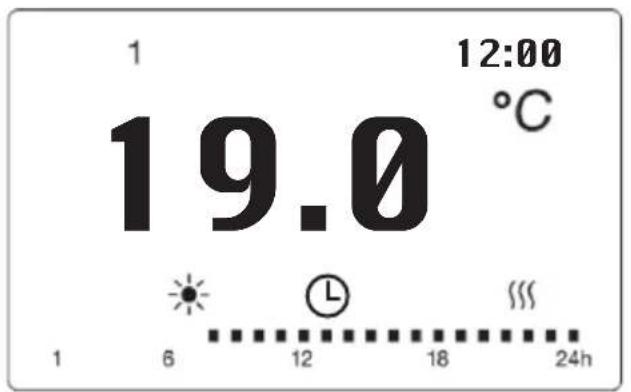
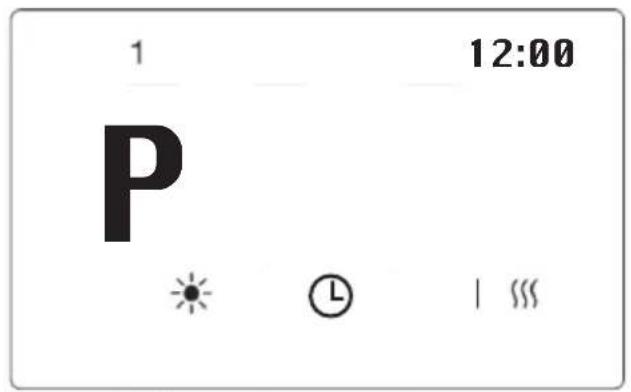
When the unit is operating in the Program mode, press and hold the OK button for 3 seconds to switch from the Program mode to the Pilot Wire mode. When the device is operating in the Pilot Wire mode, press the OK button for 3s to switch from the Pilot Wire mode to the Program mode. The interfaces of the Program and Pilot Wire modes are as follows:
text_image
1 19.0 °C 12:00 6 12 18 24hProgram mode
text_image
1 12:00 P * ① | ...Pilot wire mode
NOTE: For Program Mode, the setting and mode selection are separate. To set the program mode, press MENU to display the setup menu and select the program mode setting, then press OK to display the setup interface.
Pilot Wire Mode
- Press the ◀ /▶ buttons to select the mode Ⓛ (Program mode or Leadframe mode). In the Pilot Wire mode, select the mode via the external control (for France only).
- When the interface is in Program mode, press the OK button for 3s to switch from Program mode to Pilot wire mode.
- For countries other than France, if you choose the Pilot Wire mode, the unit will operate in the Comfort mode by default.
- Depending on the programs stored on the external programmer, the screen displays the following information received:
| pilot control mode setting | Icone display | |
| Comfort mode |  |  |
| Comfort mode |  |  |
| Comfort mode |  | 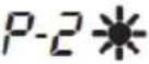 |
| Eco mode |  |  |
| Frost protection |  |  |
| Standby mode |  | |
Program Mode
- Press MENU to display the setting interface, then press◀ /▶ to select the Program Mode setting.
When Ⓛ is flashing, press OK to display the setting interface.
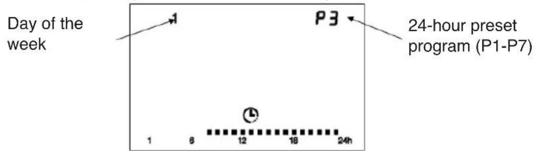
- In program mode, you can choose from 7 preset 24-hour pro-
grams (P1 to P7) corresponding to each day of the week.
NOTE: All 7 24-hour preset programs (P1 to P7) are programmable. For each hour, you can choose between comfort mode and economy mode. If you wish to configure your preferred programs from P1 to P7, please refer to the section «Configuring 7 predefined 24-hour programs (P1 to P7)».
- In program mode, the manufacturer's default settings for days of the week from 1 to 7 are as follows:
Days 1 to 5: use program P1,
Days 6 and 7: use program P3.
- The default settings for programs P1 to P7 are as follows:
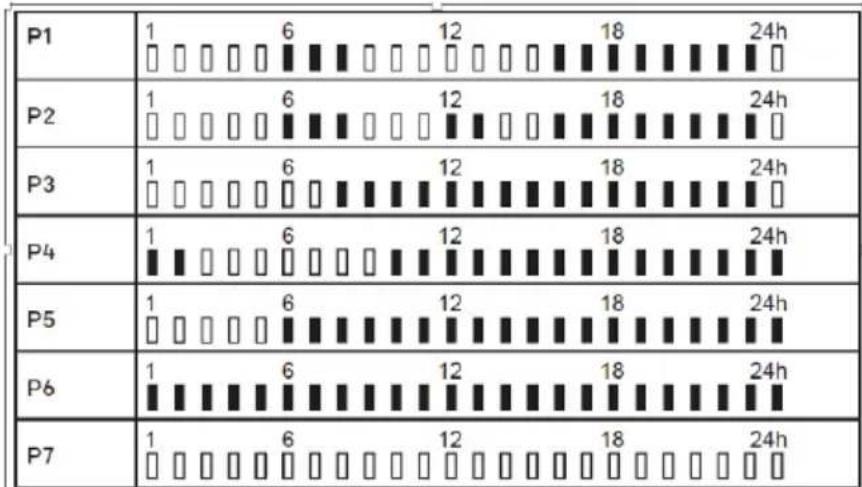
Press◀ / ▶ to select the day of the week, then press▲/▼ to select one of the 7 preset 24-hour programs (P1\~P7), or press OK to confirm the previous setting and go to the next day setting. After setting the last day, press OK to confirm or wait 30s for the unit to save automatically and return to the operation interface.
text_image
Day of the week P3 24-hour preset program (P1-P7) 1 6 12 18 24hSetting the 7 24-hour preset programs (P1\~P7)
Press MENU to enter the setting interface and ◀ / ▶ to select the program mode setting. Ⓧ
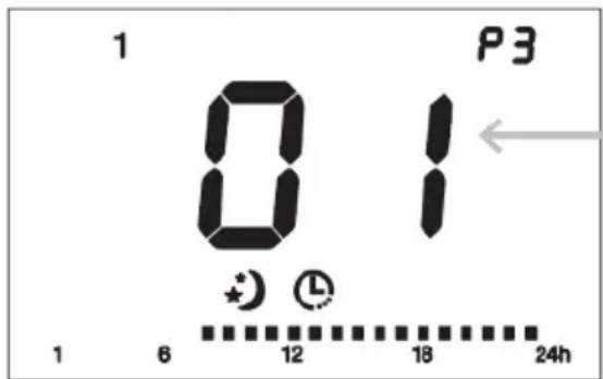
Ignore the day information, just press ▲/▼button to select a program from P1 to P7 to select a program from P1 to P7, the program number will flash. Press and hold OK for 3 seconds to enter the program setting interface.
- Press ◀ / ▶ to select the time (from 1 to 24). For each hour, two different modes are available: comfort mode and economy mode. The icon of the current setting mode for the hour flashes.
Press ▲ to select the comfort mode ▪, or press ▼ to select the economy mode ▪ (blank display), or OK to keep the previous setting. Each time you press the ▲/▼ button or the OK button, the selected comfort mode or economy mode is immediately saved and, at the same time, you automatically switch to the setting for the next hour. If you want to change the setting of the previous time, you must first press the button ◀, and then press the ▲/▼ button.
text_image
1 01 P3 1 6 12 18 24hhour (01 corresponds to hour 1 to 2, and so on. 24 corresponds to hour 24 to 1).
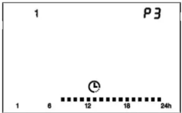
- After setting the 24th hour, press ▲/▼ or OK, the unit will automatically save the settings and return to the initial setting interface.
- For example, if you set P3 from the interface below (day 1, P3), the unit will return to the interface below (day 1, P3) when you finish setting the 24th hour of P3. The modified P3 program already replaces the manufacturer's default P3 setting.
text_image
1 P3 1 6 12 18 24hNOTES: In the event of a power failure, only the settings, temperature and operating mode will be retained in memory. When the power is restored, the clock must be reset to allow normal use of the Program Mode. After completing the program mode settings, they are saved, but the unit does not automatically start operating in the program mode. The unit does not automatically begin operating in Program Mode. You must press the left/right arrow buttons to select Program Mode and operate the heater in that mode. the heater in this mode.
3.3/ Setting the Temperature
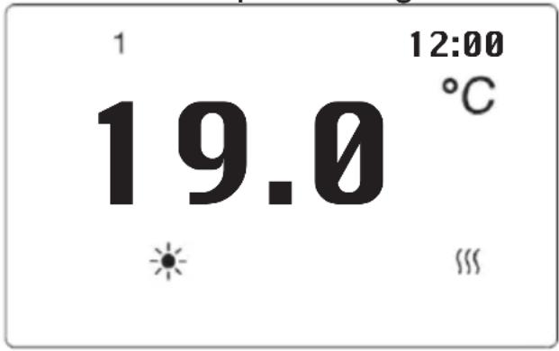
- In Comfort - or ECO mode (except Frost Protection mode), the temperature is adjustable. Press ▲/▼ to set the desired Comfort mode temperature between 5 °C and 29 °C. The temperature difference between ECO and Comfort mode is 3.5°C, so the temperature range for ECO mode is 1.5°C to 25.5°C.
- Press the buttons other than▲/▼ to finish the setting or wait for it to be automatically saved.
- When the room temperature is higher than the set temperature, the heater stops heating.
text_image
1 19.0 °C 12:00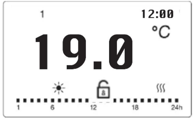
text_image
1 19.0 °C 12:00 1 6 12 18 24h3.4. Keyboard lock
Press the MENU button for 3s to activate the keyboard lock 🔒. To unlock it, press MENU again for 3s.
NOTES: 1. Keypad lock does not lock the sleep button.
- The keypad lock is automatically disabled in the following cases:
- The unit is put to sleep by pressing the button ⏻
- The device is disconnected from the power supply.
3.5. The automatic open window detection function
- Press MENU to display the setting interface and press◀ / ▶ to select the window detection function 📄. When 📄 is flashing, press OK to start the timer setting.
Press ◀ / ▶ to select «ON» or «OFF». If «ON» is selected, the automatic ventilation detection function is activated and the « ” icon will appear on the screen. Press OK to confirm or wait for 30s for the unit to save automatically and return to the operation interface.
- When the temperature drop is detected, the unit will automatically switch to frost free mode with the icon flashing. When the temperature increase is detected, the unit will return to the previous mode with the icon lit. You can choose «OFF» to deactivate the automatic ventilation detection function.
NOTE: the automatic ventilation detection function is not available in frost protection mode.
3.6. In case of power failure
All the above settings for temperature, time, date of the week and programs remain valid as long as the power supply is not interrupted. In the event of a power failure, the unit will only retain the thermostat settings, temperature and mode in memory. When the power is restored, the date and time must be set in order for the various programs to function properly.
MAINTENANCE INSTRUCTIONS
Turn off the unit and disconnect it from the power supply before cleaning or servicing. Cleaning and maintenance by the user must not be performed by unsupervised children. Clean the unit at least once a year with a vacuum cleaner to remove any dust accumulations.
Clean the exterior of the unit by wiping it with a damp cloth and drying it with a dry cloth. Never immerse the unit in water or allow water to enter the unit. The main cause of overheating is due to dust deposits or residues in the unit. Make sure that these foreign bodies are removed regularly. Isolate the unit from the mains and clean it by vacuuming the air intake and the grilles.
TROUBLESHOOTING & TECHNICAL SPECIFICATIONS
Always isolate the unit from the power supply and allow it to cool before servicing.
- TECHNICAL CHARACTERISTICS
| Model / Ref BAT- | HT10HB BAT-HT15 | HB BAT-HT20HB | |
| Nominal voltage | 230 V ~ 230 V ~ 230 | V ~ | |
| Rated frequency | 50 Hz 50 Hz 50 Hz | ||
| Rated power 1000 | W 1500 W 2000 W | ||
| Protection class II II II | |||
| Protection IP | IPX4 | IPX4 | IPX4 |
| Pilot wire | 6 orders | 6 orders | 6 orders |
- IN CASE OF PROBLEMS
| Problem | Solution |
| The unit does not heat up | Check that the circuit breakers of the installation are switched on, or that the load breaker has not cut off the power supply (if the installation has one). |
| Select the COMFORT mode. | |
| Increase the temperature setting. | |
| The unit heats up continuously | Make sure the unit is not in a draft. |
| Decrease the temperature setting. |
CONSIGNES POUR LE TRAITEMENT DES DÉCHETS INSTRUCTIONS FOR WASTE DISPOSAL

Emballage recyclable - recyclable packaging

flowchart
graph LR
    A["FR"] --> B["+"]
    B --> C["Recycle Bin"]
    C --> D["Recycle Box"]
    D --> E["Bag Bag"]
Triez et recyclez l'emballage - Sort and recycle the packaging

WWW.KITCHEN-MOVE.COM
Pour toute question / For any question: support@batimex-import.fr