
Control 414C/T Micro - Speaker JBL - Free user manual and instructions
Find the device manual for free Control 414C/T Micro JBL in PDF.

| Product type | In-ceiling loudspeaker (ultra-compact satellite) |
| Brand | JBL |
| Model | Control 414C/T Micro |
| Dimensions | Cutout diameter: 104 mm; approximate depth: 100 mm |
| Weight | Approximately 1 kg |
| Power handling | Low impedance (16 Ω) or distributed line 70 V / 100 V |
| Power rating (program) | 10 W (70 V / 100 V); 30 W (low impedance) |
| Frequency response | 100 Hz – 20 kHz |
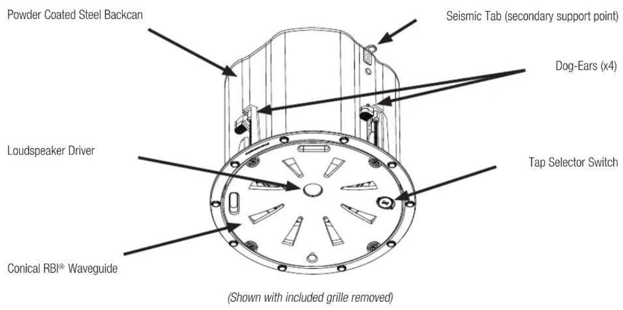
| Technology | Conical Radiation Boundary Integrator® (RBI™) for uniform coverage |
| Enclosure material | Powder-coated steel (back can) |
| Grille | Removable magnetic perforated grille, paintable |
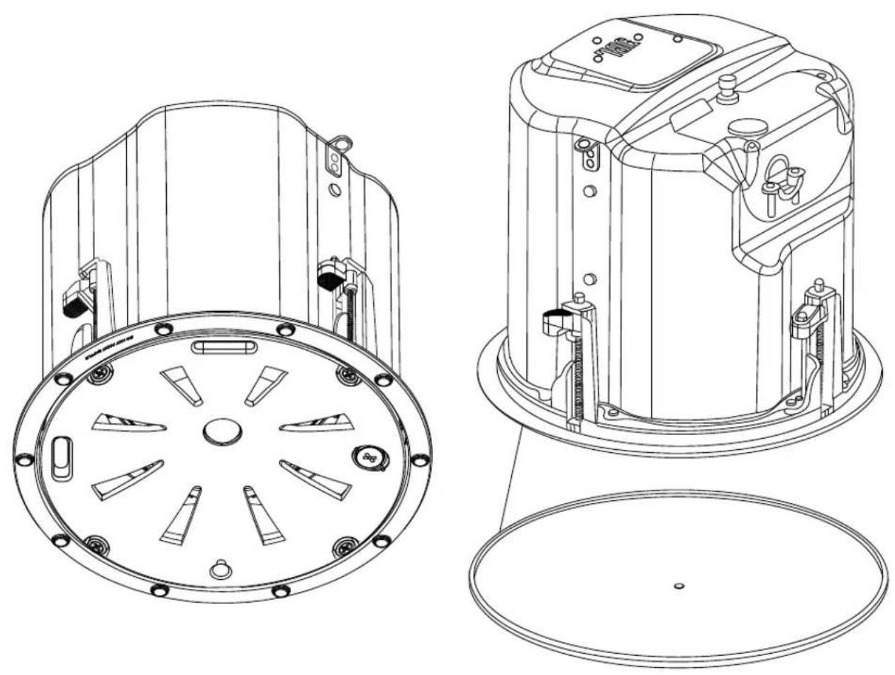
| Installation | From below ceiling; dog ears; includes C-ring |
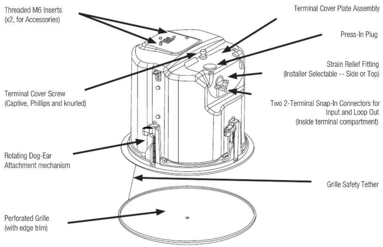
| Connections | 2 snap-in 2-pin connectors (input and loop-through output) |
| Tap selector | On front baffle: 70 V / 100 V (1.25 – 10 W) or 16 Ω bypass |
| Protection rating | IP33 (with optional rubber boots) |
| Maintenance | Clean with a dry cloth; do not paint the baffle |
| Safety | Seismic tab for safety cable; installation by qualified personnel |
| Spare parts | Optional grilles (black, square), pre-installation brackets (NC, MR) |
Frequently Asked Questions - Control 414C/T Micro JBL
User questions about Control 414C/T Micro JBL
0 question about this device. Answer the ones you know or ask your own.
Ask a new question about this device
Download the instructions for your Speaker in PDF format for free! Find your manual Control 414C/T Micro - JBL and take your electronic device back in hand. On this page are published all the documents necessary for the use of your device. Control 414C/T Micro by JBL.
USER MANUAL Control 414C/T Micro JBL
JBL Control 400 Premium Coverage series Ceiling Loudspeakers
Haut-parleurs JBL Control 400 Premium Coverage Series Enceintes de plafond JBL Control 400 Premium Coverage Series JBL Control 400 Premium Coverage Serie Deckenlautsprecher JBL Control 400 Premium Coverage 系列天花板扬声器 JBL Control 400 Premium Coverage 系列天花板喇叭 Altavoces de techo JBL Control 400 Premium Coverage JBL Control 400 프리미엄 커버리지 시리즈 천장형 라우드 스피커
natural_image
Technical line drawing of a mechanical device with multiple circular components and mounting holes (no text or symbols)Control 442C/T, Control 445C/T, Control 447C/T, Control 447LP, Control 447HC, Control 440CS/T
TABLE OF CONTENTS - SOMMAIRE - TABLE DES MATIÈRES - INHALTSÜBERSICHT - 目录 - 目錄 - ÍNDICE - 목차
JBL Control 400 Premium Coverage series Ceiling Loudspeakers....4
- Important Safety Instructions....5
- Product Descriptions ....6
- Product Feature Identification....7
- Installation Preparations ....8
- Step-by-Step Installation and Wiring....10
- Guide to Connection Pins and Hookup Schemes ...... 17
- Painting the Grille....19
- Maintenance 20
- Replacement Parts ....20
Haut-parleurs JBL Control 400 Premium Coverage Series ....21
JBL Control 400 Premium Coverage series Ceiling Loudspeakers
Control 442C/T, Control 445C/T, Control 447C/T, Control 447LP, Control 447HC, Control 440CS/T
natural_image
Technical line drawings of a mechanical device showing front and top views with internal components (no text or symbols)Owner's Manual

1. IMPORTANT SAFETY INSTRUCTIONS
LOOK FOR THESE SYMBOLS:

Read the manual before use.

The lightning flash with arrowhead symbol within an equilateral triangle is intended to alert the user to the presence of uninsulated “dangerous voltage” within the product’s enclosure that may be of sufficient magnitude to constitute a risk of electrical shock to persons.

The exclamation point, within an equilateral triangle, is intended to alert the user to the presence of important operating and maintenance (servicing) instructions in the literature accompanying the product.

High sound pressure. Hearing damage risk.
WARNING: To be installed only by instructed or skilled persons using Harman approved mounting hardware and safeguards.
- READ, KEEP, and FOLLOW all instructions. HEED all warnings.
- Install and operate only as instructed to avoid creating a safety hazard.
- This product is not intended for use in high-moisture or extended/intense sunlight (UV) environments. If exposure to these conditions is expected, cover the product appropriately or remove it from the environment.
- Clean only with a dry cloth.
- Ensure all equipment is OFF before making or breaking any connections.
- Secure the speaker grill in place before powering the apparatus or putting it into service.
- Refer all servicing to qualified service personnel. Servicing is required if the apparatus has been damaged in any way, such as by liquid or objects within the enclosure, exposure to rain or moisture, abnormal operation, or being dropped.
- DO NOT install near any heat or flame sources.
- Only use attachments/accessories specified by the manufacturer.
- The Ingress Protection rating is dependent on additional hardware, thoroughly review those installation instructions before operating the product.
WEEE NOTICE:
This product must not be disposed of or dumped with your other household waste. You are liable of dispose of all your electronic or electrical waste equipment by relocating over to the specified collection point for recycling of such hazardous waste. Isolated collection and proper recovery of your electronic and electrical waste equipment at the time of disposal will allow us to help conserving natural resources. Moreover, proper recycling of electronic and electrical waste equipment will ensure the safety of human health and the environment. For more information about electronic and electrical waste equipment disposal, recovery, and collection points, please contact your local city center, household waste disposal service, shop from where you purchased the equipment, or manufacturer of the equipment.
HARMAN Professional, Inc.
8500 Balboa Blvd. Northridge, CA 91325, USA
EU: HARMAN Professional Denmark ApS
Denmark ApS, Olof Palmes Allé 44, 8200 Aarhus N, Denmark
UK: HARMAN Professional Solutions
2 Westside, London Road, Hemel Hempstead, HP3 9TD, UK
2. PRODUCT DESCRIPTIONS
Thank you for purchasing JBL Control 400 Premium Coverage series Ceiling Loudspeakers.
Read through this manual to familiarize yourself with the features, applications and precautions before you use these products.
The JBL Control 400 Premium Coverage series Ceiling Loudspeakers is a line of premium, in-ceiling loudspeakers that offer superior sound and consistent coverage. It features JBL's proprietary conical Radiation Boundary Integrator® (RBI™) technology which offers extremely even pattern control which often allows use of fewer speakers in an installation. The Series includes six models to suit various performance & design requirements. Housed in an elegant industrial design, they deliver outstanding performance and reliability.
Control 442C/T is an ultra-compact in-ceiling satellite speaker with 2.5" mid/high driver. The speaker can be set for low-impedance (16Ω) operation or can be driven by either a 70V or 100V distributed speaker line. (SKU# is JBL-C442C/T)
Control 445C/T is a two-way in-ceiling loudspeaker with a coaxially mounted 5.25" woofer and 3/4" tweeter featuring JBL's proprietary conical Radiation Boundary Integrator® (RBI™) technology. The speaker can be set for low-impedance (8Ω) operation or can be driven by either a 70V or 100V distributed speaker line. (SKU# is JBL-C445C/T)
Control 447C/T is a two-way in-ceiling loudspeaker with a coaxially mounted 6.5" woofer and 1" tweeter featuring JBL's proprietary conical Radiation Boundary Integrator® (RBI™) technology. The speaker offers extended bass response for a warm, full-bodied tone. It can be set for low-impedance (8Ω) operation or can be driven by either a 70V or 100V distributed speaker line. (SKU# is JBL-C447C/T)
Control 447LP is a shallow, low-profile version of the Control 447C/T for locations with limited space above the ceiling. The speaker features JBL's proprietary conical Radiation Boundary Integrator® (RBITM) technology. This model has the same diameter footprint as the Control 447C/T offering uniformity of appearance in the ceiling. The shallow LP model can be used along with other full-depth models from the series for a consistent sound character. (SKU# is JBL-C447LP)
Control 447HC is ideal for use in high ceiling applications and highly reverberant spaces. It features a narrow 75° coverage pattern, which helps minimize sound reflections off of room surfaces, resulting in improved speech intelligibility. Control 447HC features the same sonic character as the Control 447C/T with a coaxially mounted 6.5" woofer and 1" tweeter and JBL's proprietary conical Radiation Boundary Integrator® (RBITM) technology. (SKU# is JBL-C447HC)
Control 440CS/T is an 8" high power in-ceiling subwoofer designed to produce powerful bass performance. It is perfect for in-ceiling sound systems requiring higher fidelity sound with low end extension. The Control 440CS/T also features a built-in passive crossover network enabling it to be used as part of a subwoofer-satellite system driven by a full-range signal. This subwoofer can be set for low-impedance (8Ω) operation or can be driven by either a 70V or 100V distributed speaker line. (SKU# is JBL-C440CS/T)
3. PRODUCT FEATURE IDENTIFICATION
4. INSTALLATION PREPARATIONS
The entire installation can be accomplished, if necessary, without requiring access above the ceiling. Bracketry for use with either suspended ceilings or sheetrock ceilings is included. The speaker is held securely in place via "dog-ear" mounting tabs which lock into place. Inputs and loop outs to the next speaker are attached to snap-in-place connector (included) which can be prewired before installing the speaker for ultra-fast snap-on installation.
OPTIONAL PRE-INSTALLATION BRACKETS
IN MOST CASES, NO BRACKETS OTHER THAN THE ONES INCLUDED WITH YOUR SPEAKER ARE REQUIRED.
Everything needed for most installations of these loudspeakers is provided with your Control Contractor ceiling speaker.
However, a particular procedure that is sometimes used for installation into sheet rock (typically gypsum board) can be facilitated by the use of JBL's optional pre-installation brackets before the sheetrock is installed. The pre-installation bracket provides a bracket to which wiring can be strapped in-place behind the sheetrock. It can function as a cutout template when many cutouts are to be made in a production-line style installation. And it can reserve a location in the ceiling prior to the sheetrock getting installed. Two types of pre-installation brackets are available from JBL Professional as optional accessories:
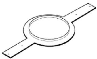
- The optional NC NEW-CONSTRUCTION BRACKET is made of flat sheet metal, with wings to attach to the building structure. Holes are drilled for nails or screws at 16 inches (406 mm) and 24 inches (610 mm) on-center. Additional holes can be drilled by the installer at other spacings up to a maximum of 24-3/4 inches (630 mm) apart. Sheet rock installs after the bracket gets installed, and the bracket provides a template for blind cutout of the hole in the sheet rock. For this process, the sheet rock is typically cut with a router-type cutting tool, using the bracket ring as a cutout guide.
natural_image
Simple line drawing of a circular component with two horizontal bars (no text or symbols)Figure 1: Optional NC New -Construction Bracket
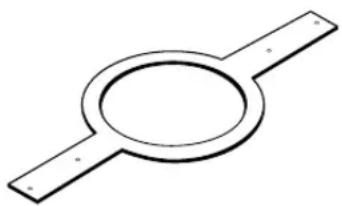
- The optional MR PLASTER-RING BRACKET (or "Mud Ring") contains a circular offset, forming an edge guide for sheet rock plastering. The bracket has wings that attach to the building structure. Sheet rock is typically either precut or cut with a rotary cutting tool using the outside of the plaster ring circle as a guide. The sheet rock hole is then plastered (or "mudded") up to the ring to create a seamless cutout.
natural_image
Simple line drawing of a circular component with two parallel plates (no text or symbols)Figure 2: Optional MR (“Mud Ring”) Plaster Ring Bracket
Table 1: Pre-Installation Brackets
| Model New Construction Bracket Plaster-Ring Bracket | ||
| Control 442C/T JBL-MTC-442NC JBL-MTC-442MR | ||
| Control 445C/T JBL-MTC-426NC JBL-MTC-426MR | ||
| Control 447C/T, Control 447LP JBL-MTC-447NC JBL-MTC-447MR | ||
| Control 447HC, Control 440CS/T JBL-MTC-419NC JBL-MTC-419MR | ||
USING INCLUDED C-BRACKET WITH SHEETROCK
For most installations, the INCLUDED C-shaped backing plate provides adequate reinforcement to the ceiling material, distributing out the clamping force from the dogears. Even if one of the dogears lands on the opening between ends of the C, the rest of the dogears will land on it, so will be sufficient support for sheetrock installations.
CEILING CUTOUT SIZES
Packaged with the speakers are cardboard cutout templates for scribing the cutout hole onto your ceiling surface.
Table 2: Cutout Sizes
| Model Cutout Size (diameter) | |
| Control 442C/T 104 mm (4.1 in) | |
| Control 445C/T 223 mm (8.8 in) | |
| Control 447C/T, Control 447LP | 282 mm (11.1 in) |
| Control 447HC, Control 440CS/T | 307 mm (12.1 in) |
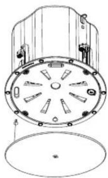
OPTIONAL BG (black) and SG (square) GRILLES
Optional round black and white square grilles are available. The JBL-MTC-xxxBG grilles are round Black Grilles that can be utilized instead of the included stock white grille when black is called for. Alternatively, the stock white grille can be painted (see below). The JBL-MTC-xxxSG are white Square Grilles that can be utilized instead of the included stock grille when a square grille is desired. These grilles can be painted to the desired color (including black). These grilles completely cover the speaker assembly.
| Model | Black Round Grilles | Square Grilles |
| Control 442C/T | JBL-MTC-442BG | JBL-MTC-442SG |
| Control 445C/T | JBL-MTC-445BG | JBL-MTC-445SG |
| Control 447C/T, Control 447LP | JBL-MTC-447BG | JBL-MTC-447SG |
| Control 447HC, Control 440CS/T JBL-MTC-440BG | JBL-MTC-440SG |
5. STEP-BY-STEP INSTALLATION AND WIRING
The installation system has been designed so that the entire installation can be accomplished from beneath the ceiling for instances when access above the tile is not possible or practical. However, in some cases it may be easier -- with removable ceiling tiles, for example -- to access from both the top and bottom of the ceiling tile during various phases of the installation.
Note: the wiring method shall be in accordance with:
(1) In Canada, CSA C22.1, Canadian Electrical Code, Part I, Safety Standard for Electrical Installations, Section 32
(2) In the United States, NFPA 70.
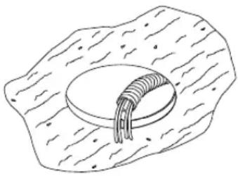
Step 1 – Cut the Hole. Cutout the hole size either by tracing the included cardboard cutout template or by scribing a hole using the cutout size chart above. Use a safe tool such as a jigsaw to cut the hole and proper eye protection. Be precise, not deviating from the cutout diameter by more than 1/16th of an inch (1.5 mm). Pull the wiring through the cutout hole.
natural_image
Simple line drawing of a biological cell or tissue structure with a central circular component (no text or labels)Figure 3:
Hole Cutout
(Shown: Wire in flex conduit)
Step 2 – Insert Backing Hardware Through the Hole.
Packaged with the speakers are two types of backing hardware – a C-shaped backing-plate ("C-ring") bracket and two tile rails.
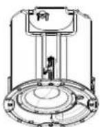
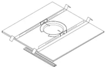
Suspended Ceilings – Insert the C-ring through the hole cut in the ceiling tile (or set it in place from above the ceiling, if there is access). Place the C-ring around the hole with the tabs located as shown on Figure 4. Insert the tile rails through the cut hole in the ceiling tile. Snap the two rails into the two tabs in the C-plate and align the rails so that the ends extend OVER the T-channel grid on the side of the tile. Secure the rails onto the C-ring tabs by inserting a screw though each tab into the rail. This can all be accomplished from below the ceiling tile, if necessary.
FOR SAFETY: IMPORTANT TO USE BRACKETS
ALL included support brackets - C-ring and tile rails -- MUST be used when installing into suspended ceiling tiles.
natural_image
Isometric line drawing of a mechanical assembly with a circular component and supporting beams (no text or symbols)Figure 4:
C-Bracket and Tile Rail Positioning on Ceiling Tile
Tile Rails: The tile rails are designed to fit either standard 24-inch-wide tiles or 600-mm-wide tiles. The tile rail pieces do NOT physically attach to the T-grid struts. Instead, the inverted-V shape at the ends of the rails sits ABOVE the T-grid strut. During normal operation, the rails are supported by the edge of the tile. In the unlikely event that the tile comes out or falls apart, the ends of the support rails are designed to catch onto the T-grid, providing secure support to hold the loudspeaker assembly in place.
Optional accessory Tile rails JBL-MTC-48TRX4 (pack of 4 Tile Rails) are also available for installation into larger 4' x 4' (1200 x 1200 mm) ceiling tiles.
Vibration Reduction: These loudspeakers can generate substantial audio output, which can cause buzzing of the ceiling materials or structure. Depending on the character of the ceiling tile and structure, the installer might need to place neoprene or other dampening material under the tile rails or the edges of the tiles to eliminate rattles.
Cutout Placement: The tile rails are pre-punched with attachment holes along their length. Placement is not limited to the center of the tile as is the case with many other tile rail support systems.
Non-Suspended Ceiling Types – For non-suspended ceiling types, the C-ring can be optionally used by itself to shore up the ceiling material and to spread out the clamping force from the tab clamps. Insert the C-ring through the cut hole in the ceiling and place it on the top side of the hole before inserting the speaker.
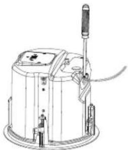
Step 3 – Plugging connectors into connector sockets in the speaker's terminal cup.
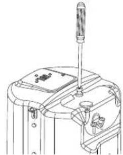
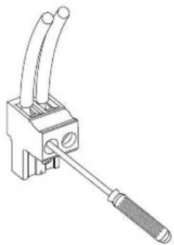
Fully loosen the captive TERMINAL COVER retaining screw that is on the top panel of the backcan. This screw remains captive in the terminal cover (do not fully remove it).
natural_image
Technical line drawing of a mechanical device with a screwdriver and lever (no text or symbols)Figure 5: Fully loosen the captive TERMINAL COVER screw
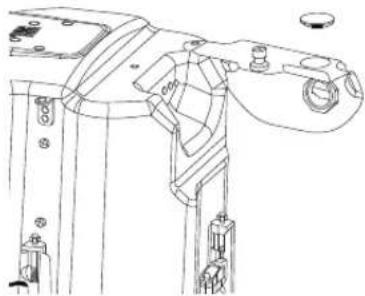
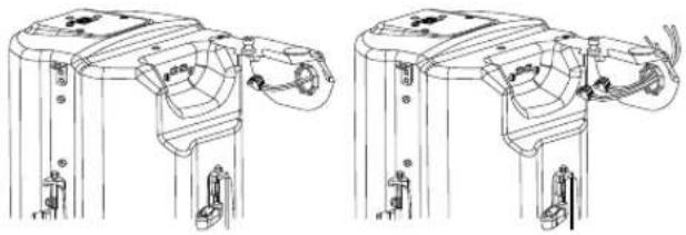
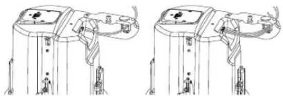
Open the TERMINAL COVER – The TERMINAL COVER hinge is on the side panel of the backcan for Control 442C/T and Control 447LP.
natural_image
Technical line drawing of a mechanical assembly with no visible text or symbolsFigure 6A: Opening TERMINAL COVER (Control 442C/T shown)
natural_image
Technical line drawing of a mechanical assembly with no visible text or symbolsFigure 6B: Opening TERMINAL COVER (Control 447LP shown)
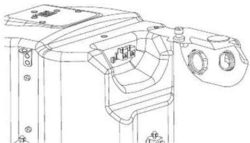
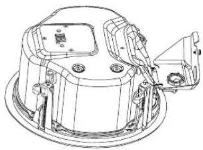
The TERMINAL COVER hinge is on the top panel of the backcan for Control 445C/T, Control 447C/T, Control 447HC and Control 440CS/T.
natural_image
Technical line drawing of a mechanical device with no visible text or symbolsFigure 6C: Opening TERMINAL COVER (Control 447C/T shown)
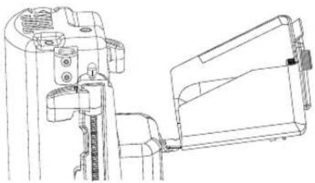
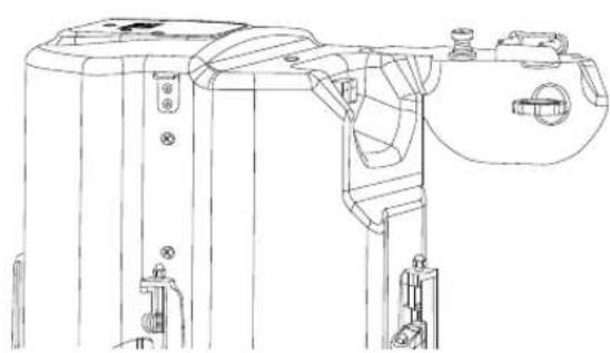
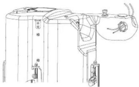
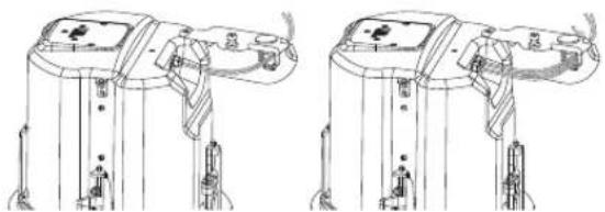
STRAIN RELIEF Location – To keep the speaker as shallow as possible, the default STRAIN RELIEF location – i.e., the wire exit – comes installed on the side of the backcan.
natural_image
Technical line drawing of a mechanical device with mounting brackets and a central clamp (no text or symbols)Figure 7: Strain relief on the side by default
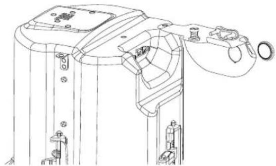
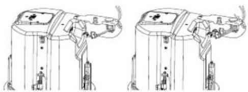
However, optionally, if the installer wants the STRAIN RELIEF to be on the top panel of the backcan instead of on the side
OPTIONAL: INSTRUCTIONS FOR MOVING STRAIN RELIEF TOP PANEL
There are two same-diameter holes in the terminal cover, one on the top panel and one on the side panel. From the factory, the top hole is fitted with a PRESS-IN Plug and the side hole has the STRAIN RELIEF assembly. To swap them, open the terminal cover and press out the PRESS-IN PLUG (retain it for later).
natural_image
Technical line drawing of a mechanical assembly with no visible text or symbolsFigure 8: Push out the PRESS-IN Plug
[Optional Steps for Moving Strain Relief to Top Panel]
From the inside of the TERMINAL COVER, unscrew the nut holding the STRAIN RELIEF.
natural_image
Technical line drawing of a mechanical assembly with mounting holes and internal components (no text or symbols)Figure 9: Unscrew the NUT
[Optional Steps for Moving Strain Relief to Top Panel]
Insert the STRAIN RELIEF into the top hole of the TERMINAL COVER. Tighten the nut holding the STRAIN RELIEF assembly.
natural_image
Technical line drawing of a mechanical device with mounting brackets and internal components (no text or symbols)Figure 10: Move the strain relief to the top and lock it
[Optional Steps for Moving Strain Relief to Top Panel]
Insert the PRESS-IN PLUG into the side hole in the TERMINAL COVER.
natural_image
Technical line drawing of a mechanical device with mounting brackets and a handle (no text or symbols)Figure 11: Insert the PRESS-IN PLUG
Step 4 – Connect the Wiring to the Removable Locking Connector(s) – Two 2-pin removable locking connectors are included with the speaker – one for IN and the other for LOOP OUT. Connect the wiring to the removable locking connectors by stripping the insulation back about 5 mm (about 3/16 inch) – stripping the wire longer risks shorting and stripping the wire shorter risks a poor connection to the connector. Insert the bare end of wire into the connector and screw down the hold-down screw until tight using a small flat blade screwdriver. Tighten any unused screws to avoid vibration. Double-check that the wires are not frayed, and that bare wire is not exposed (either of which can lead to shorting between the wires).
natural_image
Technical line drawing of a mechanical clamp or connector with two tubes and a handle (no text or symbols)Figure 12: Connecting Wires to Removeable Locking Connector
(Shown with individual un-jacketed wires, with 2 input wires)
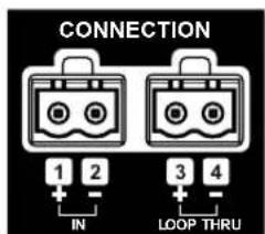
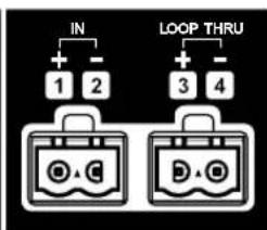
Guide to the Pins for Connection -- The 2 removable locking input connectors contain 2 terminals each. The pin functions are listed on the label located on the terminal cover plate.
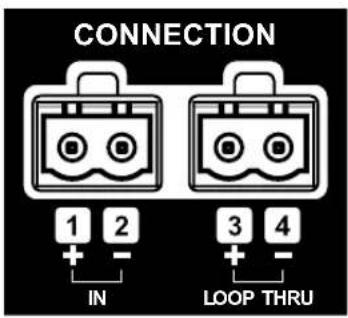
Figure 13: Connector Pins (Control 447C/T shown)
Pins 1 & 2 (on one of the 2-pin connectors) are the "+" and "-" inputs to the loudspeaker. Pins 3 & 4 are the loop-through connections to subsequent loudspeakers. Pins 3 & 4 are connected to pins 1 & 2, respectively (Pin 1 connects to Pin 3 and Pin 2 connects to Pin 4) inside the speaker.
Slide the already-wired 2-pin connector(s) through the STRAIN RELIEF
Connect speaker wire to 2-pin connectors(s)
- Wiring Connector(s) – Connect speaker wire to connectors, observing proper +/- polarity and making sure there are no frayed strands of wire or excessive exposed conductors exposed that could short together.
natural_image
Technical line drawing of two mechanical device components with no visible text or symbolsFigure 14: Slide connectors through strain relief
If IP33 rating is desired, then use Rubber Boot(s) and follow these instructions:
[Optional steps for Connect the Wiring to the Removable Locking Connector(s)]
Slide wire through strain relief from external to internal
natural_image
Technical line drawing of a mechanical device with no visible text or symbolsFigure 15: Slide wire through strain relief
[Optional steps for Connect the Wiring to the Removable Locking Connector(s)]
Slide wire through the rubber boot from the small square opening and out from the other opening
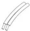
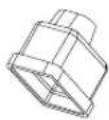
Figure 16: Slide the wire through the rubber boot
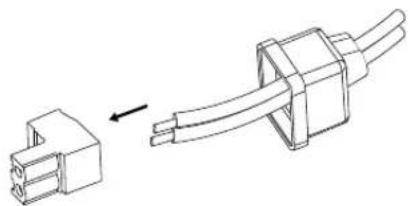
[Optional steps for Connect the Wiring to the Removable Locking Connector(s)]
Connect wire cord to the connector

natural_image
Technical line drawing of a connector with an arrow indicating assembly (no text or symbols)Figure 17: Connect wire cord to the connector
[Optional steps for Connect the Wiring to the Removable Locking Connector(s)]
Lock the connector with screwdriver
natural_image
Technical line drawing of a mechanical clamp or connector with no visible text or symbolsFigure 18: Lock the connector with screwdriver
[Optional steps for Connect the Wiring to the Removable Locking Connector(s)]
Slide Rubber boot close to the plug.
natural_image
Technical line drawing of a mechanical device with two views (top and side), no visible text or symbolsFigure 19: Slide Rubber boot close to the plug
[Optional steps for Connect the Wiring to the Removable Locking Connector(s)]
Add silicone glue on the opening of Rubber boot as shown to seal the joint.

natural_image
Technical line drawing of a mechanical or electrical component with two connectors and a directional arrow (no text or symbols)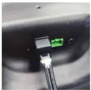
natural_image
Close-up of a black connector with a green pin inserted, showing no visible text or symbols.Figure 19A: Add silicone glue
Step 5 – Plug the already-wired 2-pin connector(s) into the 2-pin SOCKET(S) – Observe proper plus and minus polarity and orient the connectors in accordance with the label.
natural_image
Technical line drawing of a mechanical device with two views (top and side), showing internal components and mounting points (no text or symbols)Figure 20: Plug connectors into the sockets if no rubber boots
natural_image
Technical line drawing of two identical mechanical components with no visible text or symbolsFigure 21: Plug connectors into the sockets and move the rubber boot to cover the connectors if rubber boots are used
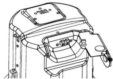
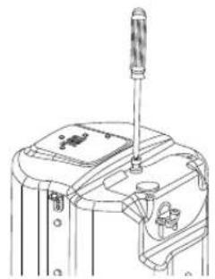
Step 6 – Close and Secure TERMINAL COVER – Close the terminal cover and secure it with the screw that is captive in the TERMINAL COVER.
natural_image
Technical line drawing of a mechanical device with a screwdriver and base mount (no text or symbols)Figure 22: Closing TERMINAL COVER and tightening the screw
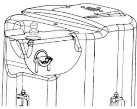
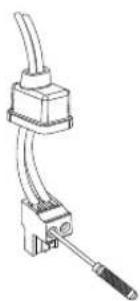
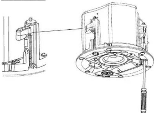
Step 7 – Tighten STRAIN RELIEF clamping mechanism with the included 2 screws.
natural_image
Technical line drawing of a cylindrical device with a handle and base mount (no text or symbols)Figure 23: Tightening the Strain Relief Clamping Mechanism (Shown with STRAIN RELIEF on the side location and with unjacketed wires)
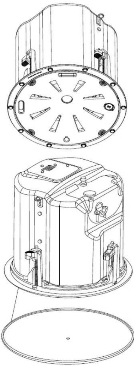
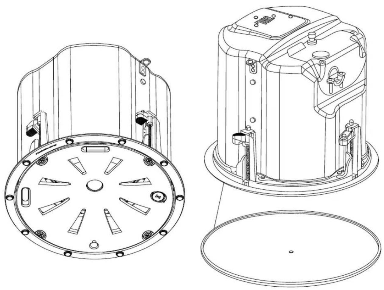
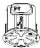
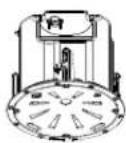
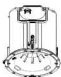
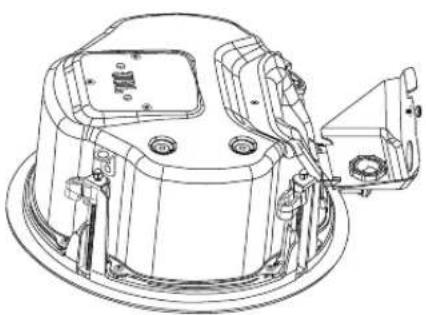
Step 8 – Insert the Speaker into the Ceiling and Tighten.
Insert the speaker into the ceiling cutout as far as it goes, until the back of the front baffle rim touches the ceiling.
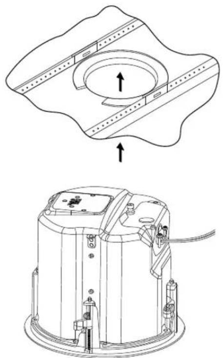
natural_image
Technical line drawing of a mechanical device with an open circular component and internal components (no text or symbols)Figure 24: Insert Speaker through Ceiling Cutout
Tighten Dogears -- IMPORTANT -- For each attachment screw, FIRST turn 1/2 turn COUNTER-CLOCKWISE to release the dog-ear mounting tab from its storage location.
Then tighten the mounting tabs by turning the screw CLOCKWISE until tight onto the top of the ceiling surface. Adjust the torque to meet the characteristics of the ceiling material DO NOT For use in thick ceilings – By default, dogear tab is in the middle of the travel and for most ceiling depths it can be used as it is. For thick ceilings where the tabs need to be at their highest position, turn all the screws COUNTER-CLOCKWISE till the hard stop (while making sure the tab is not held in the middle), before inserting the speaker through the ceiling cutout.
OVERTIGHTEN.
natural_image
Technical line drawing of a mechanical assembly with no visible text or symbolsFigure 25: Tighten Dogear Mounting Tabs Number of Dog-Ears, by Model
| Model | Number of Dog-Ear screws |
| Control 442C/T 2 dog-ears | |
| Control 445C/T, Control 447C/TControl 447LP, Control 447HC,Control 440CS/T | 4 dog-ears |
When removing the speaker, rotate all the dogear screws in a COUNTER-CLOCKWISE direction until each screw stops. Once all the screws have reached a hard stop the dogears will be folded, and the speaker can be removed from the ceiling.
Make sure to support the speaker when loosening the dogear screws to prevent speaker from falling.
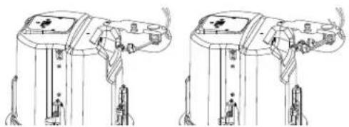
Step 9 – Connect a Secondary Support Line to SEISMIC
TAB – A tab is provided on the side of each speaker for connection to an independent secondary support point. Some construction codes require using this secondary support point, which requires connecting a support line to a separate secure support point on the building structure. Consult construction codes in your region.
IMPORTANT:

Control Contractor ceiling speakers can generate substantial vibration. A secondary support cable to the seismic tab should be used as a secondary support point in case the ceiling tile or support structure breaks.
Step 10 – Adjust Tap Selector – The tap selector switch is located on the front baffle. Adjust the tap setting before placing the grille and before applying signal to the speaker. In some installations it is advisable to leave the grilles OFF to allow final adjustment of the taps for the system.
"NC" = No Connection. (Do not use this setting with a 100V distributed system)
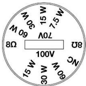
Figure 26: Tap Selector (Control 447C/T shown)
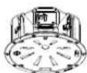
Step 11 – Insert the safety Tether fastening plug and Attach the Grille – The grille comes with a safety tether tied to it. Insert the fastening plug at the open end of the tether (which comes pre-attached to the grille) into the included socket on the baffle. Make sure the plug is inserted completely in the socket and does protrude out blocking the grille from attaching properly.
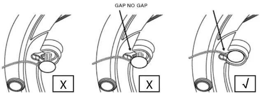
Figure 27: Ensure the plug is inserted fully
Then position the grill in front of the speaker, taking care not to run the tether cable directly in front of one of the drivers (or else it could buzz with vibration). Make sure the grille is held securely magnetically in place such that it will not loosen or fall due to vibration.
natural_image
Technical line drawing of a mechanical component with circular housing and mounting holes (no text or symbols)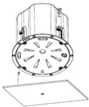
natural_image
Technical line drawing of a mechanical component with circular housing and mounting holes (no text or symbols)Figure 28: Attach the Grille
6. GUIDE TO CONNECTION PINS AND HOOKUP SCHEMES
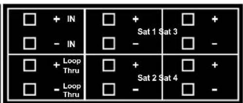
There are two (2) removable locking input connectors with two (2) terminals on each for the Control 442C/T, Control 445C/T, Control 447C/T, Control 447LP and Control 447HC. On Control 440CS/T there are six (6) terminals. The pin functions are listed on the label located on the can.
flowchart
graph TD
    A["IN"] --> B["1"]
    A --> C["2"]
    D["LOOP THRU"] --> E["3"]
    D --> F["4"]
Control C442C/T: Control C445C/T, C447C/T, LP & HC:
Control C440CS/T:
Figure 28: Connection Pins on various models
To wire Control 400 Premium Coverage Series loudspeakers simply connect the positive wire to the “+” pin and connect the negative wire to the “-” pin. The “IN” pins are in connected to the “LOOP THRU” pins (+ and - respectively) inside the loudspeaker. The “Loop Thru” pins allow a parallel connection to an additional loudspeaker.
To select the operating mode or desired transformer tap of the loudspeaker, simply rotate the tap selector switch located on the front of the baffle to the desired setting.
Note: Both 70V/(100V) connections and low impedance connections are made via the same input pins. When using the transformer tap selections, be sure that the power amplifier is set on 70V/(100V) mode and the leads feeding the system are connected to 70V/(100V) outputs on the amplifier.
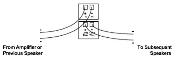
Hookup Schemes for Subsequent Speakers
Using Loop-Through Terminals -- By connecting the wire pair of a subsequent speakers to the "Loop Thru" on the Control 400 Premium Coverage Series Loudspeakers all subsequent speakers will be disconnected when this speaker's connector is disconnected during troubleshooting. This can be useful to isolate problems to a section of the distributed line while leaving the wires attached to the connector.
flowchart
graph TD
    A["From Amplifier or Previous Speaker"] --> B["+"]
    A --> C["-"]
    D["To Subsequent Speakers"] --> E["+"]
    D --> F["-"]
    B --> G["+"]
    C --> H["-"]
    G --> I["Loop Using Time"]
    H --> J["Loop Using Time"]
    I --> K["+"]
    J --> L["+"]
Figure 29: Using Loop-Thru Terminals
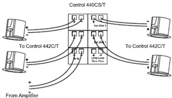
Hookup Schemes for Subwoofer-Satellite Systems Using Control 440CS/T and Control 442C/T
The Control 440CS/T subwoofer features a built-in crossover network designed for use with the Control 442C/T Ultra-Compact Satellite loudspeakers. Two or four Control 442C/T satellite loudspeakers can be used with the Control 440CS/T to create an extremely natural sounding and powerful subwoofer-satellite system that is perfect for applications requiring wide bandwidth and superior sonic performance with minimal visual impact. Using four Control 442C/T satellite loudspeakers with a Control 440CS/T will offer approximately twice the area coverage of a system using only two Control 442C/T satellite loudspeakers.
The Control 440CS/T and Control 442C/T Sub-Sat system can be driven either via a 70V/(100V) distributed line or in low impedance direct mode. The Control 442C/T speakers need to be set for low Impedance (16Ω) operation using the tap selector and connected to satellite output connectors located on the Control 440CS/T. With the Transformer Tap/Bypass switch set to the bypass/8Ω low impedance mode, the Control 440CS/T subwoofer itself presents an 8Ω load on your amplifier, and a two-satellite system also creates an 8Ω load on your amplifier, whereas a four- satellite system creates a 4Ω load.
Choose whichever of the following hookup patterns best accommodates your installation. All satellite speakers must terminate at the Control 440CS/T subwoofer.
Connecting the Control 442C/T Satellite to the Control 440CS/T Subwoofer.
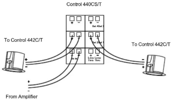
Satellite Home Run to Subwoofer -- There are four satellite output connectors on the Control 440CS/T. If using only two Control 442C/T satellites, connect each loudspeaker to a single output connector as shown in the diagram below; one Control 42C in "Sat 1" and the second Control 42C to "Sat 2" ONLY. "Sat 3" and "Sat 4" connectors should not be used.
flowchart
graph TD
    A["To Control 442C/T"] --> B["Control 440CS/T"]
    A --> C["To Control 442C/T"]
    B --> D["From Amplifier"]
    B --> E["Loop Loop Thru Thru"]
    B --> F["Sat 45at 1"]
    B --> G["Sat 25at 1"]
Figure 30: Connecting two Control 442C/T
If using four Control 442C/T satellites, connect each loudspeaker to a single output connector as shown in the diagram below, one Control 442C/T to "Sat 1", the second Control 442C/T to "Sat 2", the third Control 442C/T to "Sat 3" and the fourth Control 442C/T to "Sat 4."
flowchart
graph TD
    A["To Control 442C/T"] --> B["Control 440CS/T"]
    A --> C["To Control 442C/T"]
    D["From Amplifier"] --> B
    D --> C
    B --> E["5x1 45x1 3"]
    B --> F["5x1 25x1 1"]
    B --> G["LongLoop Thru Thru"]
    C --> H["5x1 45x1 3"]
    C --> I["5x1 25x1 1"]
    C --> J["LongLoop Thru Thru"]
Figure 31: Connecting four Control 442C/T
Use only either two or four satellite loudspeakers as described in the recommended configurations. Do not use one or three satellite speakers, or it could result in uneven sound levels and / or damage to your sound system.
Note: Apart from Satellite-Subwoofer application, Control 442C/T can also be used independently in either low-impedance (16Ω) or in a 70V or 100V distributed speaker line setting.
7. PAINTING THE GRILLE
For Premium Coverage Series models, the grille's white finish complements most decor and does not need further finishing. Where the interior design requires it, these grilles are easy to paint. The grille covers the entire speaker, so it can be painted prior to speaker installation.

IMPORTANT:
DO NOT paint the baffle of the speaker. Having paint between the magnet and the grille would diminish the ability of the magnets to hold the grille.
For best results, it is recommended to use the following procedure:
- Gently remove the grille backing material from the back of the grille without tearing it. Set it aside for re-application after painting. Either mask or remove the grille logo (for reapply after painting). Do NOT remove the edge trim.
- Clean the grille and edge trim with a light solvent such as mineral spirits by rubbing the item with a lightly dampened cloth. Do not, however, use abrasives such as sandpaper or steel wool (which can remove the grille's rust resistant plating). Do not use gasoline, kerosene, acetone, MEK, paint thinner, harsh detergents or other chemicals. Use of these cleaners may result in permanent damage to the grille assembly. Do not sand the grille.
- Spray one or more thin coats of paint. Be careful not to fill in the perforation holes (they are needed for the sound to go through – occluding them will harm the sound quality of the speaker).
- After the paint has thoroughly dried, reinstall the grille backing material to the back of the grille. If the grille backing has shrunk since removal, stretch it back to size to mask properly. If the grille backing has stretched since removal, trim to size.
- If the tackiness remaining on the back of the grille is not enough to securely hold the backing material in place (or if it got covered over by the paint), apply a very light coat of spray adhesive to the back of the grille.
- Lightly spray the adhesive to the BACK OF THE GRILLE rather than to the front of the backing material. If an adhesive says to spray both sides, use a different adhesive. Spraying adhesive on the front of the backing material can expose glue to the open air through the perforations, which can attract and hold dust from the air, impairing the clean look of the speaker.
- DO NOT place the front of grille on any surface where additional adhesive may have been sprayed. Doing so can deposit adhesive on the front of the grille surface, and similarly attract and hold dust and dirt.
- If the JBL logo was removed (rather than simply being masked), re-apply the JBL logo to the center of the grille. There is a shallow indent in the center of the grille to indicate where the logo goes.
Mask the Speaker If the Ceiling Gets Painted – The speaker itself should not be painted. The grille completely covers the speaker, and the speaker's front baffle is black to properly disappear visually behind the grille and grille backing material. If the ceiling gets painted after the speaker is in place, it's important to fully mask the speaker (including the edges of the baffle) prior to such painting so that no paint gets onto the drivers, or onto the baffle where any inconsistencies in color may be visible through the grille.
8. MAINTENANCE
No maintenance is required when installed in accordance with installation and wiring guidelines described in this manual.
9. REPLACEMENT PARTS

There are no user serviceable parts inside these speakers. Refer servicing to an authorized JBL Service Center. For the name of an authorized Service Center in your area, contact JBL Professional at the appropriate address from those listed on page 5.
Haut-parleurs JBL Control 400 Premium Coverage Series
Control 442C/T, Control 445C/T, Control 447C/T, Control 447LP, Control 447HC et Control 440CS/T
1. CONSIGNES IMPORTANTES DE SÉCURITÉ
HARMAN Professional, Inc.
8500 Balboa Blvd. Northridge, CA 91325, USA
EU: HARMAN Professional Denmark ApS
Denmark ApS, Olof Palmes Allé 44, 8200 Aarhus N, Denmark
UK: HARMAN Professional Solutions
2 Westside, London Road, Hemel Hempstead, HP3 9TD, UK
2. DESCRIPTIONS DES PRODUITS
natural_image
Simple line drawing of a circular component with two horizontal bars, no text or symbols present.Figure 1: Support de fixation optionnel NC NEW-CONSTRUCTION BRACKET
natural_image
Simple line drawing of a circular component with two horizontal bars, no text or symbols present.natural_image
Simple line drawing of a coiled string inside a circular container (no text or symbols)natural_image
Isometric line drawing of a mechanical assembly with a circular component and supports (no text or symbols)natural_image
Technical line drawing of a mechanical device with screwdriver and housing (no text or symbols)natural_image
Technical line drawing of a mechanical assembly with no visible text or symbolsnatural_image
Technical line drawing of a mechanical device with mounting holes and housing (no text or symbols)Figure 6B: Ouvrir le COUVRE-BORNES (Control 447LP illustré)
natural_image
Technical line drawing of a mechanical component with no visible text or symbolsnatural_image
Technical line drawing of a mechanical device with no visible text or symbolsnatural_image
Technical line drawing of a mechanical assembly with no visible text or symbolsnatural_image
Technical line drawing of a mechanical assembly with mounting brackets and housing (no text or symbols)natural_image
Technical line drawing of a mechanical device with mounting brackets and a handle (no text or symbols)natural_image
Technical line drawing of a mechanical device with mounting holes and internal components (no text or symbols)Figure 11: Insérer le BOUCHON ENFICHABLE
natural_image
Technical line drawing of a mechanical clamp or connector (no text or symbols)natural_image
Technical line drawing of two mechanical components with mounting brackets and wiring (no text or symbols)natural_image
Technical line drawing of a mechanical device with no visible text or symbolsnatural_image
Technical line drawing of two connected electrical connectors, one with a pin and arrow indicating assembly (no text or symbols)natural_image
Technical line drawing of a mechanical clamp or connector with no visible text or symbolsnatural_image
Technical line drawing of a mechanical device with no visible text or symbols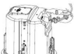
natural_image
Technical line drawing of a mechanical device with no visible text or symbolsnatural_image
Technical line drawing of a mechanical or electrical component with no visible text or symbols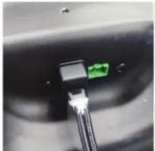
natural_image
Close-up of a black connector with a green connector inserted into a white cable (no visible text or symbols)natural_image
Line drawing of a mechanical device with no visible text or symbols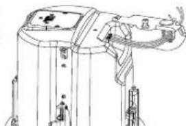
natural_image
Technical line drawing of a mechanical device with no visible text or symbolsnatural_image
Technical line drawing of a mechanical device with no visible text or symbols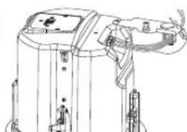
natural_image
Technical line drawing of a mechanical device with no visible text or symbolsnatural_image
Technical line drawing of a mechanical device with a screwdriver and base components (no text or symbols)Figure 22: Fermer le COUVRE-BORNES et serrer la vis
natural_image
Technical line drawing of a mechanical device with no visible text or symbolsnatural_image
Technical line drawing of a mechanical device with an open circular component and internal components, showing assembly steps (no text or symbols)natural_image
Technical line drawing of a mechanical device with a close-up view showing internal components (no text or symbols)natural_image
Technical line drawings of two circular mechanical components with mounting holes and a base plate (no text or symbols)Figure 28: Attacher la grille
6. GUIDE DES BROCHES DE CONNEXION ET DES SCHÉMAS DE BRANCHEMENT
No maintenance is required when installed in accordance with installation and wiring guidelines described in this manual.
9. PIÈCES DE RECHANGE

1. CONSIGNES DE SÉCURITÉ IMPORTANTES
SOYEZ ATTENTIF AUX SYMBOLES SUIVANTS :

HARMAN Professional, Inc.
8500 Balboa Blvd. Northridge, CA 91325, USA
EU: HARMAN Professional Denmark ApS
Denmark ApS, Olof Palmes Allé 44, 8200 Aarhus N, Denmark
UK: HARMAN Professional Solutions
2 Westside, London Road, Hemel Hempstead, HP3 9TD, UK
2. DESCRIPTION DES PRODUITS
natural_image
Simple line drawing of a circular component with two horizontal bars, no text or symbols present.natural_image
Simple line drawing of a circular component with two horizontal bars, no text or symbols present.natural_image
Simple line drawing of a coiled string inside a circular container (no text or symbols)Illustration 3 :
Découpe du trou
natural_image
Isometric technical drawing of a mechanical assembly with a circular component and flanged base (no text or symbols)Illustration 4 :
natural_image
Technical line drawing of a mechanical device with a screwdriver and base mount (no text or symbols)natural_image
Technical line drawing of a mechanical assembly with no visible text or symbolsnatural_image
Technical line drawing of a mechanical assembly with no visible text or symbolsnatural_image
Technical line drawing of a mechanical assembly with no visible text or symbolsnatural_image
Line drawing of a mechanical device with internal components and mounting brackets (no text or symbols)natural_image
Technical line drawing of a mechanical assembly with no visible text or symbolsnatural_image
Technical line drawing of a mechanical assembly with mounting holes and housing (no text or symbols)natural_image
Technical line drawing of a mechanical device with mounting brackets and a cylindrical component (no text or symbols)natural_image
Technical line drawing of a mechanical device with mounting brackets and control knobs (no text or symbols)natural_image
Technical line drawing of a mechanical clamp or connector (no text or symbols)natural_image
Technical line drawing of two mechanical components with mounting brackets and internal channels (no text or symbols)natural_image
Technical line drawing of a mechanical device with no visible text or symbolsnatural_image
Technical line drawing of two connected electrical connectors (no text or symbols)natural_image
Line drawing of a mechanical clamp or connector with no visible text or symbolsnatural_image
Technical line drawing of a mechanical device with two views (top and side), showing internal components and assembly lines without any text or symbols.natural_image
Technical line drawing of a mechanical or electrical component with no visible text or symbols
natural_image
Close-up of a black connector with a green connector inserted into the socket, connected to wires (no visible text or symbols)natural_image
Technical line drawing of a mechanical device with two views (top and side), no visible text or symbolsnatural_image
Technical line drawing of a mechanical device with two views (top and side), showing internal components and mounting points (no text or symbols)natural_image
Technical line drawing of a mechanical device with a screwdriver and base mount (no text or symbols)natural_image
Technical line drawing of a cylindrical industrial device with a vertical stirrer and control panel (no text or symbols)natural_image
Pure technical diagram of a mechanical component with no text, numbers, or symbols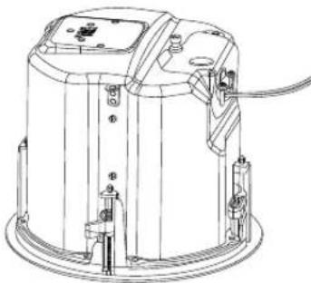
natural_image
Technical line drawing of a cylindrical industrial machine with mounting brackets and wiring (no text or symbols)natural_image
Technical line drawing of a mechanical assembly with a close-up view of a circular component (no text or symbols)natural_image
Technical line drawings of two circular mechanical components with internal blades and mounting holes, shown from different angles (no text or symbols)natural_image
Technical line drawing of a mechanical device showing front and top views with internal components (no text or symbols)Benutzerhandbuch

ACHTEN SIE AUF DIESE SYMBOLE:

HARMAN Professional, Inc.
8500 Balboa Blvd. Northridge, CA 91325, USA
EU: HARMAN Professional Denmark ApS
Denmark ApS, Olof Palmes Allé 44, 8200 Aarhus N, Denmark
UK: HARMAN Professional Solutions
2 Westside, London Road, Hemel Hempstead, HP3 9TD, UK
natural_image
Simple line drawing of a circular component with two parallel plates (no text or symbols)Abbildung 1:
natural_image
Simple line drawing of a circular component with two parallel plates (no text or symbols)Abbildung 2:
natural_image
Simple line drawing of a coiled string inside a circular container (no text or symbols)Abbildung 3
Lochausschnitt
natural_image
Isometric line drawing of a mechanical assembly with a circular component and rectangular supports (no text or symbols)Abbildung 4:
natural_image
Technical line drawing of a mechanical device with a screwdriver and base mount (no text or symbols)natural_image
Technical line drawing of a mechanical assembly with no visible text or symbolsnatural_image
Technical line drawing of a mechanical device with mounting holes and housing (no text or symbols)natural_image
Technical line drawing of a mechanical device with no visible text or symbolsnatural_image
Technical line drawing of a mechanical device with no visible text or symbolsnatural_image
Technical line drawing of a mechanical assembly with no visible text or symbolsnatural_image
Technical line drawing of a mechanical assembly with mounting brackets and housing (no text or symbols)natural_image
Technical line drawing of a mechanical device with mounting brackets and a handle (no text or symbols)natural_image
Technical line drawing of a mechanical device with mounting brackets and a handle (no text or symbols)natural_image
Technical line drawing of a mechanical clamp or connector (no text or symbols)natural_image
Technical line drawings of two mechanical device components with no visible text or symbolsnatural_image
Technical line drawing of a mechanical device with no visible text or symbolsnatural_image
Technical line drawing of two mechanical components: a cylindrical rod and a flanged housing (no text or symbols)natural_image
Technical line drawing of two connected electrical connectors (no text or symbols)natural_image
Line drawing of a mechanical clamp or connector with no visible text or symbolsnatural_image
Technical line drawing of a mechanical device with two views (top and side), no visible text or symbolsnatural_image
Technical line drawing of a mechanical or electrical component with no visible text or symbols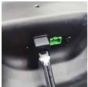
natural_image
Close-up of a black connector with a green connector inserted, showing wiring (no visible text or symbols)natural_image
Technical line drawing of a mechanical device with multiple ports and mounting brackets (no text or symbols)natural_image
Technical line drawing of two identical mechanical components with no visible text or symbolsnatural_image
Technical line drawing of a mechanical device with a screwdriver and base components (no text or symbols)natural_image
Technical line drawing of a mechanical device with no visible text or symbolsnatural_image
Pure technical diagram of a mechanical component with no text, numbers, or symbols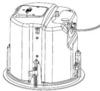
natural_image
Technical line drawing of a mechanical device with mounting brackets and wiring (no text or symbols)natural_image
Technical line drawing of a mechanical device with a close-up view of its internal components (no text or symbols)natural_image
Technical line drawings of two circular mechanical components with internal blades and mounting holes, shown from different angles (no text or symbols)natural_image
Technical line drawings of a mechanical device showing front and top views with internal components (no text or symbols)用户手册

1. 重要安全说明
注意以下符号:

使用前请阅读手册。

natural_image
Simple line drawing of a circular component with two horizontal bars (no text or symbols)图1: 可选NC新建支架
natural_image
Simple line drawing of a circular component with two horizontal bars, no text or symbols present.natural_image
Simple line drawing of a biological structure with a central circular element and textured surrounding surface (no text or symbols)natural_image
Isometric line drawing of a mechanical assembly with a circular component and rectangular plates (no text or symbols)natural_image
Technical line drawing of a mechanical component with a screwdriver and mounting base (no text or symbols)natural_image
Technical line drawing of a mechanical assembly with no visible text or symbols图6A: 打开端子盖
(图示为Control 442C/T)
natural_image
Technical line drawing of a mechanical assembly with no visible text or symbolsnatural_image
Technical line drawing of a mechanical device with internal components and mounting brackets (no text or symbols)图6C: 打开端子盖
(图示为Control 447C/T)
natural_image
Technical line drawing of a mechanical device with internal components (no text or symbols)natural_image
Technical line drawing of a mechanical component with no visible text or symbols图8: 推出压入式塞子
[将应力消除组件移至顶部面板的可选步骤]
从端子盖内部,拧下固定应力消除的螺母。

natural_image
Technical line drawing of a mechanical assembly with mounting holes and housing (no text or symbols)图9: 拧下螺母
[将应力消除组件移至顶部面板的可选步骤]
natural_image
Technical line drawing of a mechanical device with mounting brackets and a cylindrical housing (no text or symbols)图10:将应力消除组件移至顶部并锁定
natural_image
Technical line drawing of a mechanical device with mounting holes and internal components (no text or symbols)图11: 插入压入式塞子
natural_image
Technical line drawing of a mechanical clamp or connector (no text or symbols)natural_image
Technical line drawings of two mechanical components with no visible text or symbols图14:将接头穿过应力消除组件
natural_image
Technical line drawing of a mechanical device with no visible text or symbolsnatural_image
Technical line drawing of two mechanical components: a cylindrical rod and a flanged housing (no text or symbols)图16: 将电线穿过橡胶护套
[将电线连接到可拆卸锁定接头的可选步骤]
将电线连接到接头
natural_image
Diagram showing two types of electrical connectors: a small component and a larger connected component with wires (no text or symbols present)图17: 将电线连接到接头
natural_image
Line drawing of a mechanical clamp or connector with no visible text or symbols图18: 用螺丝刀锁定接头
[将电线连接到可拆卸锁定接头的可选步骤] 将橡胶护套滑向插头。
natural_image
Technical line drawing of two identical mechanical components with no visible text or symbols图19: 将橡胶护套滑向插头
[将电线连接到可拆卸锁定接头的可选步骤]
natural_image
Technical line drawing of a mechanical or electrical component with no visible text or symbols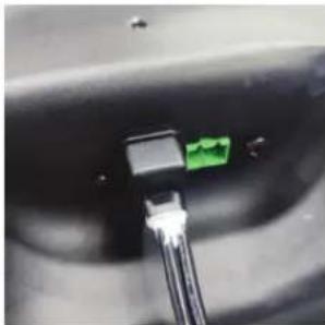
natural_image
Close-up of a black connector with a green connector inserted into a cable (no visible text or symbols)图19A: 添加硅胶
natural_image
Technical line drawing of a mechanical device with two views (top and side), no visible text or symbolsnatural_image
Technical line drawing of two identical mechanical components with no visible text or symbolsnatural_image
Technical line drawing of a mechanical device with a screwdriver and base plate (no text or symbols)图22: 关闭端子盖并拧紧螺钉
natural_image
Technical line drawing of a mechanical device with a central lever and base mount (no text or symbols)图23: 拧紧应力消除夹紧机构
natural_image
Diagram of a circular mechanical component with directional arrows indicating movement or force (no text or symbols)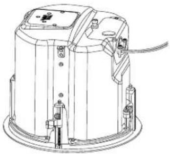
natural_image
Technical line drawing of a mechanical device with mounting holes and wiring (no text or symbols)图24:将扬声器插入天花板切口
natural_image
Technical line drawing of a mechanical device with a close-up view showing internal components (no text or symbols)图25: 拧紧折耳安装片
各型号的折耳数量
| 型号 折耳螺钉数量 | |
| Control 442C/T | 2个折耳 |
| Control 445C/T、Control 447C/TControl 447LP、Control 447HC、Control 440CS/T | 4个折耳 |
图26: 抽头选择器
(图示为Control 447C/T)
natural_image
Technical line drawings of two circular mechanical components with internal blades and mounting holes, shown from top and side views (no text or symbols)图28: 安装网罩
6. 连接引脚与接线方案指南
natural_image
Technical line drawings of a mechanical device showing front and top views with internal components (no text or symbols)用戶手冊

1. 重要安全說明
注意以下符號:

使用前請閱讀手冊。

natural_image
Simple line drawing of a circular component with two horizontal bars (no text or symbols)圖1: 可選NC新建支架
natural_image
Simple line drawing of a circular component with two horizontal bars, no text or symbols present.natural_image
Simple line drawing of a biological structure with textured background and central circular element (no text or symbols)natural_image
Isometric line drawing of a mechanical assembly with a circular component and rectangular plates (no text or symbols)natural_image
Technical line drawing of a mechanical device with a screwdriver and base plate (no text or symbols)圖5:完全松開端子蓋固定螺釘
natural_image
Technical line drawing of a mechanical assembly with no visible text or symbolsnatural_image
Technical line drawing of a mechanical assembly with no visible text or symbols圖6B: 打開端子蓋 (圖示為Control 447LP)
natural_image
Technical line drawing of a mechanical device with no visible text or symbolsnatural_image
Technical line drawing of a mechanical device with internal components (no text or symbols)圖7:預設情況下應力消除位於側面
natural_image
Technical line drawing of a mechanical assembly with no visible text or symbols圖8: 推出壓入式塞子
natural_image
Technical line drawing of a mechanical assembly with mounting brackets and housing (no text or symbols)圖9:擰下螺母
[將應力消除組件移至頂部面板的可選步驟]
natural_image
Technical line drawing of a mechanical device with mounting brackets and a handle (no text or symbols)圖10:將應力消除組件移至頂部並鎖定
natural_image
Technical line drawing of a mechanical device with mounting brackets and a handle (no text or symbols)圖11: 插入壓入式塞子
natural_image
Technical line drawing of a mechanical clamp or connector (no text or symbols)natural_image
Technical line drawing of two identical mechanical components with mounting brackets and wiring (no text or symbols)圖14:將接頭穿過應力消除組件
natural_image
Technical line drawing of a mechanical device with no visible text or symbols圖15:將電線穿過應力消除組件
natural_image
Technical line drawing of two mechanical components: a cylindrical rod and a flanged housing (no text or symbols)圖16:將電線穿過橡膠護套
natural_image
Technical line drawing of two connected electrical connectors (no text or symbols)圖17:將電線連接到接頭
natural_image
Technical line drawing of a mechanical clamp or connector assembly (no text or symbols)圖18:用螺絲刀鎖定接頭
natural_image
Technical line drawing of two identical mechanical components with no visible text or symbols圖19:將橡膠護套滑向插頭
natural_image
Technical line drawing of a mechanical or electrical component with two connectors and a directional arrow (no text or symbols)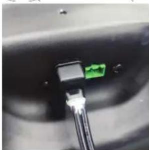
natural_image
Close-up of a black connector with a green pin inserted, showing internal wiring (no text or symbols visible)圖19A: 添加矽膠
natural_image
Technical line drawing of two identical mechanical components with no visible text or symbolsnatural_image
Technical line drawing of two identical mechanical components with no visible text or symbolsnatural_image
Technical line drawing of a mechanical device with a screwdriver and base mount (no text or symbols)圖22:關閉端子蓋並擰緊螺釘
natural_image
Technical line drawing of a mechanical device with no visible text or symbols圖23:擰緊應力消除夾緊機構
natural_image
Technical line drawing of a mechanical device with an internal circular component and a base view showing internal components (no text or symbols)圖24:將揚聲器插入天花板切口
natural_image
Technical line drawing of a mechanical assembly with a cylindrical component and a side view showing internal components (no text or symbols)圖25: 擰緊折耳安裝片
各型號的折耳數量
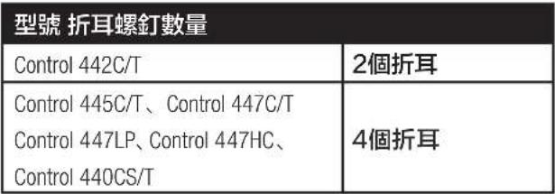 |
圖26:抽頭選擇器
(圖示為Control 447C/T)
圖27:確保插頭完全插入
natural_image
Technical line drawings of two circular mechanical components with internal blades and mounting brackets (no text or symbols)圖28: 安裝網罩
6. 連接引腳與接線方案指南
natural_image
Technical line drawings of a mechanical device showing front and top views with internal components (no text or symbols)HARMAN Professional, Inc.
8500 Balboa Blvd. Northridge, CA 91325, USA
EU: HARMAN Professional Denmark ApS
Denmark ApS, Olof Palmes Allé 44, 8200 Aarhus N, Denmark
UK: HARMAN Professional Solutions
2 Westside, London Road, Hemel Hempstead, HP3 9TD, UK
2. DESCRIPCIONES DE PRODUCTO
natural_image
Simple line drawing of a circular component with two horizontal bars (no text or symbols)natural_image
Simple line drawing of a circular component with two parallel plates (no text or symbols)natural_image
Simple line drawing of a circular object with a coiled string inside, resting on a textured surface (no text or symbols)natural_image
Isometric line drawing of a mechanical assembly with a circular component and rectangular supports (no text or symbols)natural_image
Technical line drawing of a mechanical device with a screwdriver and base plate (no text or symbols)natural_image
Technical line drawing of a mechanical assembly with no visible text or symbolsnatural_image
Technical line drawing of a mechanical device with mounting holes and internal components (no text or symbols)natural_image
Technical line drawing of a mechanical device with no visible text or symbolsFigura 6C: Apertura de TAPA DE TERMINALES (imagen del Control 447C/T)
natural_image
Technical line drawing of a mechanical device with internal components (no text or symbols)natural_image
Technical line drawing of a mechanical assembly with no visible text or symbolsnatural_image
Technical line drawing of a mechanical assembly with mounting holes and housing (no text or symbols)Figura 9: Desenroscar la TUERCA
natural_image
Technical line drawing of a mechanical device with mounting brackets and a handle (no text or symbols)natural_image
Technical line drawing of a mechanical device with mounting brackets and a handle (no text or symbols)natural_image
Technical line drawing of a mechanical clamp or connector (no text or symbols)natural_image
Technical line drawings of two mechanical components with mounting brackets and internal mechanisms (no text or symbols)natural_image
Technical line drawing of a mechanical device with no visible text or symbolsnatural_image
Technical line drawing of three mechanical components: a cylindrical rod, a flanged housing, and a separate bracket (no text or symbols)natural_image
Technical line drawing of two connected electrical connectors (no text or symbols)natural_image
Technical line drawing of a mechanical clamp or connector with no visible text or symbolsnatural_image
Technical line drawing of a mechanical device with two views (top and side), no visible text or symbolsnatural_image
Technical line drawing of a mechanical or electrical component with no visible text or symbols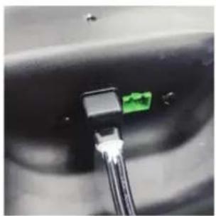
natural_image
Close-up of a black connector with a green connector inserted into a cable (no visible text or symbols)Figura 19A: Añadir pegamento de silicona
natural_image
Technical line drawing of a mechanical device with two views (top and side), no visible text or symbolsnatural_image
Technical line drawing of two identical mechanical components with no visible text or symbolsnatural_image
Technical line drawing of a mechanical device with a screwdriver and mounting base (no text or symbols)natural_image
Technical line drawing of a mechanical device with a central sensor and base mount (no text or symbols)natural_image
Diagram of a circular mechanical component with directional arrows, no text or symbols present
natural_image
Technical line drawing of a cylindrical industrial device with mounting brackets and internal components (no text or symbols)natural_image
Technical line drawing of a mechanical assembly with a clamping mechanism and a circular housing (no text or symbols)Figura 26: Selector de tomas
natural_image
Technical line drawings of two circular mechanical components with internal blades and mounting holes (no text or symbols)Figura 28: Fijar la rejilla
natural_image
Technical line drawings of a mechanical device showing front and top views with internal components (no text or symbols)사용 설명서

1. 중요 안전 지침
기호 찾아보기:

사용 전에 설명서를 읽으십시오.

HARMAN Professional, Inc.
8500 Balboa Blvd. Northridge, CA 91325, USA
EU: HARMAN Professional Denmark ApS
Denmark ApS, Olof Palmes Allé 44, 8200 Aarhus N, Denmark
UK: HARMAN Professional Solutions
2 Westside, London Road, Hemel Hempstead, HP3 9TD, UK
2.제품 설명
natural_image
Simple line drawing of a circular component with two horizontal bars (no text or symbols)natural_image
Simple line drawing of a circular component with two parallel plates (no text or symbols)natural_image
Simple line drawing of a circular object with a coiled string inside, resting on a textured surface (no text or symbols)그림 3: 구멍 절단부
(그림: 연선관 안쪽 전선)
natural_image
Isometric line drawing of a mechanical assembly with a circular component and support brackets (no text or symbols)그림 4:
natural_image
Technical line drawing of a mechanical device with a screwdriver and base mount (no text or symbols)natural_image
Technical line drawing of a mechanical assembly with no visible text or symbolsnatural_image
Technical line drawing of a mechanical device with mounting holes and internal components (no text or symbols)natural_image
Technical line drawing of a mechanical assembly with no visible text or symbolsnatural_image
Line drawing of a mechanical device with internal components and mounting holes (no text or symbols)natural_image
Technical line drawing of a mechanical assembly with no visible text or symbolsnatural_image
Technical line drawing of a mechanical assembly with mounting holes and housing (no text or symbols)그림 9: 너트 풀기
natural_image
Technical line drawing of a mechanical device with mounting holes and internal components (no text or symbols)natural_image
Technical line drawing of a mechanical device with mounting brackets and a handle (no text or symbols)그림 11:프레스인 플러그 삽입
natural_image
Technical line drawing of a mechanical clamp or connector (no text or symbols)natural_image
Technical line drawing of two mechanical components with no visible text or symbolsnatural_image
Technical line drawing of a mechanical device with no visible text or symbolsnatural_image
Technical line drawing of a connector assembly showing a pin and cable connection (no text or symbols)natural_image
Technical line drawing of a mechanical clamp or connector with no visible text or symbolsnatural_image
Technical line drawing of two identical mechanical components with no visible text or symbolsnatural_image
Technical line drawing of a mechanical or electrical component with no visible text or symbols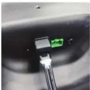
natural_image
Close-up of a black connector with a green connector inserted into a cable (no visible text or symbols)그림 19A: 실리콘 접착제 처리
natural_image
Technical line drawing of a mechanical device with two views (top and side), no visible text or symbolsnatural_image
Technical line drawing of two identical mechanical device components with no visible text or symbolsnatural_image
Technical line drawing of a mechanical device with a screwdriver and lever (no text or symbols)natural_image
Technical line drawing of a mechanical device with a central knob and base mount (no text or symbols)natural_image
Technical line drawing of a mechanical device with internal components and an external assembly (no text or symbols)natural_image
Technical line drawing of a mechanical assembly with a clamping device and a circular housing (no text or symbols)그림 26: 탱 선택기
(Control 447C/T 그림)
natural_image
Technical line drawings of two circular mechanical components with internal blades and mounting holes, shown from top and side views (no text or symbols)그림 28:그릴 부착