
T0788 - Lighting Vaxcel - Free user manual and instructions
Find the device manual for free T0788 Vaxcel in PDF.

| Product type | LED outdoor light fixture with motion sensor and photocell |
| Brand | Vaxcel |
| Model | T0788 |
| Power supply | 120 V AC, 60 Hz |
| Maximum power | 28 W |
| Operating temperature range | -25°C to 45°C (-13°F to 113°F) |
| GFCI rated current | 15 A |
| Detection range | Up to 21.35 m (70 ft) at 25°C |
| Detection angle | 240° |
| Recommended installation height | 2.45 m (8 ft) above ground |
| Sensitivity adjustment | High (H), Medium (M), Low (L) |
| Time delay adjustment | 30 seconds, 1 minute, 3 minutes |
| Adjustable color temperature | 2700 K (warm white), 4000 K (neutral white), 5000 K (cool white) |
| Operating modes | Test, Off, Auto, PC (dusk to dawn), 3H (3 hours), Manual override |
| Manual override function | Yes, by quickly cycling the wall switch |
| Built-in GFCI | Yes, with Reset and Test buttons |
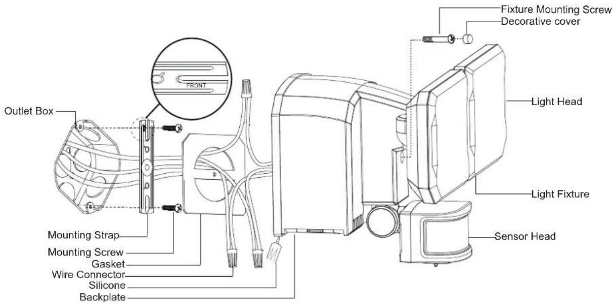
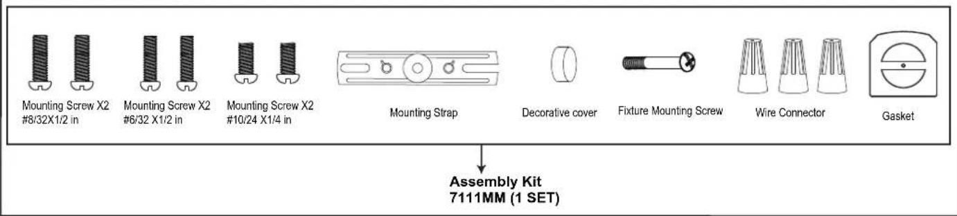
| Included hardware | Mounting screws (3 sets), mounting bracket, decorative cover, fixture mounting screws, wire connectors, gasket |
| Warranty | 5-year limited (manufacturing and finish defects) |
| Maintenance | Gently clean the sensor lens with a soft cloth every 1-2 months |
Frequently Asked Questions - T0788 Vaxcel
User questions about T0788 Vaxcel
0 question about this device. Answer the ones you know or ask your own.
Ask a new question about this device
Download the instructions for your Lighting in PDF format for free! Find your manual T0788 - Vaxcel and take your electronic device back in hand. On this page are published all the documents necessary for the use of your device. T0788 by Vaxcel.
USER MANUAL T0788 Vaxcel
ASSEMBLY AND INSTALLATION INSTRUCTIONS
T0788
WARNING: TO AVOID RISK OF ELECTRICAL SHOCK, BE SURE TO SHUT OFF POWER BEFORE INSTALLING OR SERVICING THIS FIXTURE.
NOTES: 1. Before installing, consult local electrical codes for wiring and grounding requirements.
- Read and save these instructions.
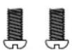
Hardware Package (included):
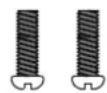
Mounting Screw X2 #8/32X1/2 in

Mounting Screw X2 #6/32 X1/2 in
Mounting Screw X2 #10/24 X1/4 in
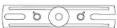
Mounting Strap

Decorative cover
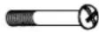
Fixture Mounting Screw
Wire Connector
Gasket
Tools Needed:

Phillips-head Screwdriver
Phillips-head screwdriver for attaching mounting screws to mounting strap, mounting bracket and fixture to mounting bracket.
Important to Know:
- This fixture requires a 120 VAC, 60 Hz power source.
- For general safety and to avoid any possible damage to the sensor, be sure the power is switched "off" before adjustment.
- If you are not familiar with state and local electrical codes, it is recommended that you consult with a qualified electrician.
- Do not connect this light fixture to a dimmer switch or timer.
Maximum Wattage: 28 W
Working Temperature Range: - 13°F \~ 113°F
GFCI Rated Current: 15A
GFCI Rated Current is 15A suitable for through wiring on 20A branch circuits
Features:
- Energy saving LED fixture.
- Motion sensor: turns light ON automatically when motion is detected and turns light OFF or remains in low-level brightness when motion stops.
- Photocell keeps the light OFF during daylight hours.
- When in manual override mode, use wall switch to keep the light ON full brightness during the night.
Note: Fixture can be wall mounted.
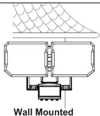
Light fixture and sensor should be mounted as shown above when installed.
Installation Steps
Turn off the power at fuse or circuit box
- Install the mounting strap to the outlet box with the stamped word "FRONT" facing away from the outlet box, using two mounting screws that best fit the outlet box. (Choose one matching pair of suitable mounting screws from the 3 pairs provided)
- Thread the fixture wires through gasket, then attach the gasket into backplate of the fixture.
- Connect the house ground wire and the fixture ground wire (green) using a wire connector. Connect a fixture black wire to the house black wire and the fixture white wire to the house white wire using wire connectors provided. Carefully tuck the wires back into the outlet box.
- Attach the backplate of the light fixture to the mounting strap, then secure it with the fixture mounting screw. Push the decorative cover firmly into the fixture mounting screw hole on the light fixture.
- With silicone caulk compound (not included), caulk completely around where the backplate of the fixture meets the wall surface.
CAUTION: Be sure to caulk completely where the backplate meets the wall surface to prevent water from seeping into the light fixture and outlet box.
Turn on the power at fuse or circuit box
Adjusting the Sensor Head:
- a: Aim sensor head toward desired detection area, maintaining a 5^ - 40^ downward angle to allow moisture to drain.
Note: Make sure sensor head is positioned with control knob facing towards the ground.
b: You can rotate the sensor head up and down to change the coverage area. (See Fig.1)
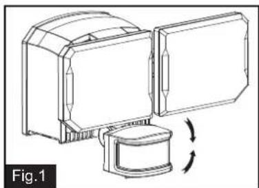
natural_image
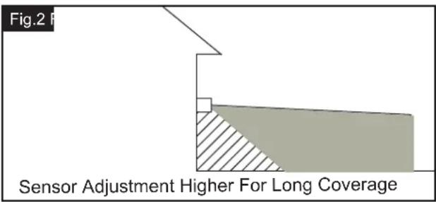
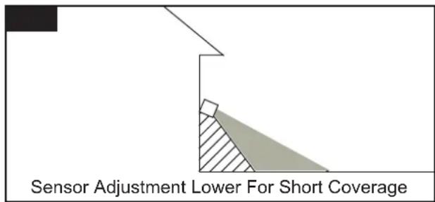
Technical line drawing of a mechanical device with a rotating component (no text or symbols)- Note: Range set too high may increase false triggering. (See Fig.2, Fig.3)
Sensitivity of Motion Sensor
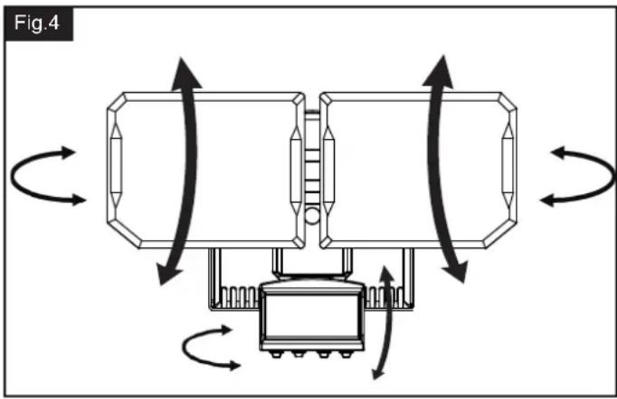
- You can adjust the sensitivity of the motion sensor by using the "SENS" selector located on the right side of the sensor head. (See Fig.4)
- Adjust motion sensor sensitivity to HIGH (H), MEDIUM (M), or LOW (L) to achieve desired performance.
- Approximate range for each setting: 70 ft. (H), 45 ft. (M), 20 ft. (L).
Adjusting the Light Head:
- Adjust the light head up or down, left or right for desired area. Keep the light heads at least 1" (25mm) away from the sensor. (See Fig.4)
- Keep the light heads (B) face down around 30 degrees angle to avoid water damage and electrical shock.
natural_image
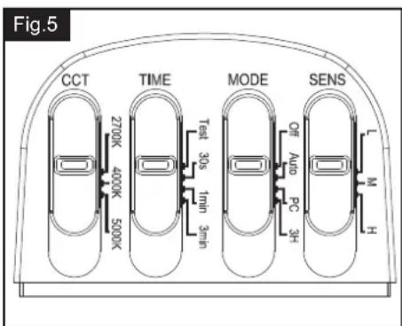
Diagram of a mechanical or electrical component with bidirectional arrows indicating rotation, no text or symbols presentChoose a mode by sliding the switch on the bottom of the sensor of the fixture. (See Fig.5)
Note: When power is first applied, the light will be on and warm up lasts 15 seconds.
-
TEST MODE (daytime and nighttime operation.)
-
Slide the "TIME" switch on the sensor head to the "Test" position.
- The light turns to high-level brightness (5000K) when motion is detected, and stays on as long as the motion continues. Then it reverts back to low-level brightness (2700K) about 5 seconds after motion is no longer detected.
- OFF MODE (nighttime operation only)
- In "OFF" mode, slide the "TIME" switch to the desired time (30s/1min/3min). At dusk, the light stays off. The light turns to high-level brightness (5000K) when motion is detected, and stays on as long as motion continues. When the motion is no longer detected, it remains on for the predetermined shut-off delay time you set (30s/1min/3min), and then turns off automatically.
- The light turns off automatically at dawn.
- AUTO MODE (nighttime operation only)
- In "AUTO" mode, slide the "TIME" switch to the desired time setting (30s/1min/3min). At dusk, the light turns on to low-level brightness. When motion is detected, the light turns to high-level brightness (5000K) and stays on as long as motion continues. When the motion is no longer detected, the light at high-level brightness (5000K) remains on for the predetermined time you set (30s/1min/3min), then switches back to low-level brightness automatically.
- The light turns off automatically at dawn.
Note: You can adjust the low-level brightness color temperature (2700K/4000K/5000K) by using the "CCT" slider switch on the sensor head. (See Fig.5)
-
PC MODE (nighttime operation only)
-
In "PC" mode, the light turns on at full brightness at dusk and remains on until dawn.
Note: You can adjust the full brightness color temperature (2700K/4000K/5000K) by using the "CCT" slider switch on the sensor head. (See Fig.5)
5. 3 HOURS (3H) MODE (nighttime operation only)
- In "3H" mode, the light turns to high-level brightness at preselected color temperature (2700K/4000K/5000K) in dusk, and stays "ON" for 3 hours, then it turns to low-level brightness at preselected color temperature (2700K/4000K/5000K). It turns to high-level brightness (5000K) when motion is detected, and stays on as long as motion continues. When motion is no longer detected, it remains on for the predetermined shut-off delay time you set (30s/1min/3min), then returns to the predetermined low level brightness automatically.
- The light turns off automatically at dawn.
Note: You can adjust the CCT color (2700K/4000K/5000K) by using the "CCT" slider switch on the sensor head. (See Fig.5)
6. Manual Override (nighttime operation only)
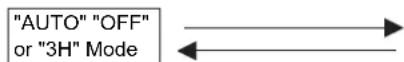
- To temporarily override the settings in "OFF" or "AUTO" or "3H" mode for on-demand continuous high-level brightness at night, turn the wall switch "OFF" then turn it "ON" twice within 3 seconds, the light remains on all night long. To shift back to "OFF" or "AUTO" or "3H" mode, turn the wall switch "OFF" then turn it "ON" twice within 3 seconds again. (See Fig.6)
- The light turns off automatically at dawn.
Note: To make sure the above functions operate properly, always keep the wall switch in the "ON" position (including the daytime).
Customization Options:
Shut-off Delay
- The shut-off delay is the length of time the light will stay at brightness after motion is detected.
- You can set the shut-off delay by pushing the Time slider switch so it points to the desired time setting (30s/1min/3min).
Notes:
- The sensitivity of the motion sensor will increase as the environmental temperature gets cooler. For best performance, gently clean the lens with a soft cloth every 1 or 2 months to ensure maximum sensitivity.
-
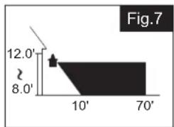
For best performance, install fixture at least 8 feet above the ground. At such a height, the fixture will provide a detection distance of up to 70 feet at 77 degrees Fahrenheit. (See Fig.7)
-
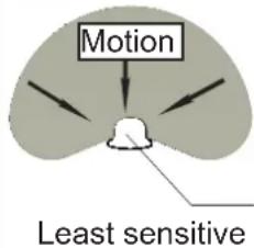
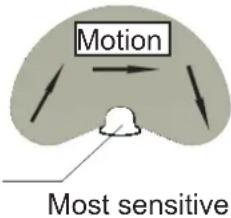
The sensor detects movement across a detection range of 240 degrees. (See Fig.8)
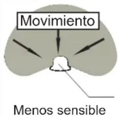
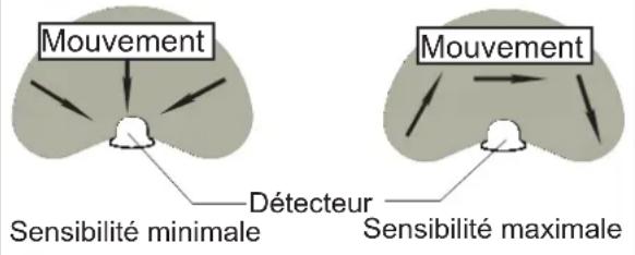
- The sensor will be more sensitive to motion across its detection path than motion directly towards it. (See Fig.9)
- To reduce possible nuisances, do not mount the fixture near a heat source like an air conditioner, vent or furnace exhaust, or in a direction facing any reflective object or other nearby light source.
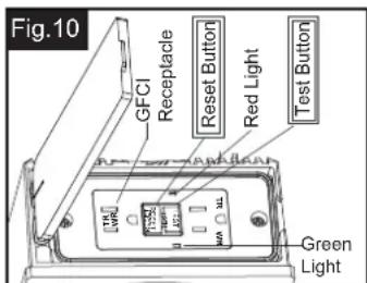
Please follow these steps to test the GFCI to work properly. (See Fig.10)
Step 1: Press the RESET button on the GFCI receptacle, the RESET button will stay in, the indicator light will illuminate in green and the power is on.
Step 2: Press the TEST button. The indicator light will turn off, the flow of electricity for the GFCI receptacle will shut off, the RESET button will pop out from its "ON" position.
Step 3: Press the RESET button to restore power, the GFCI receptacle will work properly.
Fig.6
Manual Override Operation Diagram
Turn wall switch OFF-ON-OFF-ON in 0.5\~3 Seconds
Turn wall switch OFF-ON-OFF-ON in 0.5\~3 Seconds
Where you install your fixture is important: Be sure the light is mounted straight on the wall or eave; otherwise, the detection distance may be limited.
bar
| X-Axis | Value | |---|---| | 12.0' | 12.0' | | 8.0' | 8.0' | | 10' | (not labeled) | | 70' | (not labeled) |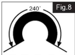
Fig.9
Sensor
Note: Red light life end alarm.
Spare Parts List:
TROUBLESHOOTING
| Problem | Possible Cause Solution | |
| The light does not work. | ☐ The light switch is turned off.☐ The fuse is blown or the circuit breaker is turned off.☐ Daylight turn-off (photocell) is in effect.☐ The circuit wiring is incorrect (if this is a new installation).☐ The motion sensor is aimed in the wrong direction.☐ The outside air temperature is close to the same as a person's body heat. | ☐ Turn the light switch on.☐ Replace the fuse or turn the circuit breaker on.☐ Recheck after dark.☐ Verify the wiring is correct.☐ Re-aim the motion sensor to cover the desired area.☐ Increase the "SENS" setting. |
| The light comes on during the day. | ☐ The motion sensor may be installed in a relatively dark location.☐ The "TIME" switch is in the "TEST" position. | ☐ The light fixture is operating normally under these circumstances☐ Set the "TIME" switch to the 30s, 1min, 3min setting. |
| The light comes on for no apparent reason. | ☐ The motion sensor may be sensing small animals or automobile traffic.☐ The "SENS" switch is set too high.☐ The outside temperature is much warmer or cooler than a person's body heat (summer or winter).☐ The light fixture is wired through a dimmer or timer. | ☐ Decrease the "SENS" setting or reposition the motion sensor.☐ Decrease the "SENS" setting.☐ Decrease the "SENS" setting.☐ Do not use a dimmer or timer to control the light fixture. Replace the dimmer or timer with a standard on/off wall switch. |
| The lights turn off too late in the PC setting. | ☐ The light fixture may be installed in a relatively dark location. | ☐ Relocate the light fixture. |
| The lights stay on continuously. | ☐ The motion sensor may be picking up a heat source, such as an air vent, dryer vent, or brightly painted, heat-reflective surface.☐ The motion sensor is in manual mode.☐ The light fixture is wired through a dimmer or timer.☐ The light fixture is on the same circuit as a motor, transformer, or fluorescent bulb. | ☐ Decrease the "SENS" setting or reposition the motion sensor.☐ Switch the motion sensor to auto. See Using manual mode on page 5.☐ Do not use a dimmer or timer to control the light fixture. Replace the dimmer or timer with a standard on/off wall switch.☐ Install the light fixture on a circuit without motors, transformers, or fluorescent bulbs. |
| The lights flash on and off. | ☐ Heat or light from the lamp heads may be turning the motion sensor on and off.☐ Heat is being reflected from other objects and may be turning the motion sensor on and off.☐ The motion sensor is in "TEST" mode and warming up. | ☐ Reposition the lamp heads away from the motion sensor.☐ Decrease the "SENS" setting or reposition the motion sensor.☐ While in "TEST" mode, the light only stays on for 5 seconds. Set the "TIME" switch to 30s,1min, 3min. |
| The lights flash once then stay off in manual mode. | ☐ The motion sensor is detecting light from the lamp heads. | ☐ Reposition the lamp heads to keep the area below the motion sensor relatively dark. |
| The GFCI box will not work. | ☐ There may be a poor connection between the fixture light and supply wires inside the outlet box.☐ The screw in the GFCI is loose.☐ RESET button was not pressed. | ☐ Check supply wire connections.☐ Make sure the screw is tight.☐ Press the RESET button. |
natural_image
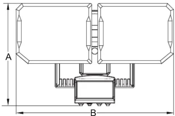
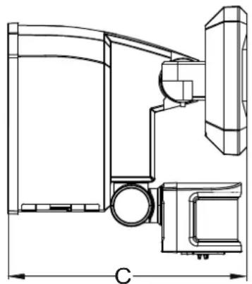
Technical line drawing of a mechanical assembly with dimension label C (no text or symbols present)A: 6-3/4"
B: 10-1/2"
C: 6-1/2"
5 Year Limited Warranty
Vaxcel warrants all of our products against defects in workmanship and finishes for one year following the date of shipment.
In addition:
- Any product with an integrated motion sensor or dusk-to-dawn photocell is supported by a 5-year warranty for the functionality of the product.
- Any product with integrated LED modules is covered by a 5-year warranty on the LED functionality.
Exclusions: This warranty does not include the failure of products from extreme acts of nature; environmental conditions not suited for the products intended use; operation in temperatures outside of the range specified in the instruction manual; usage with improper power supply, power surges or dips. For coastal locations, some corrosion is considered normal for the environment.
Vaxcel reserves the right to repair, replace or issue a credit for any properly installed product, provided it is returned per RMA instruction. This warranty is limited to the cost of the product only and does not extend to transportation, installation or replacement costs.
How can warranty service be obtained?
info@vaxcel.com
1-800-482-9235
natural_image
Technical line drawing of a mechanical assembly with no visible text or symbolsMontaje en la pared
natural_image
Technical line drawing of a mechanical device with a rotating component (no text or symbols)natural_image
Diagram showing a structural cross-section with hatched shading and a small square marker, labeled 'Fig. 2' (no text or symbols within the diagram itself)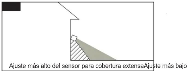
natural_image
Diagram of a mechanical device with rotating arrows indicating motion, no text or symbols presentFUNCIÓN Y OPERACIÓN
bar
Fig. 7 | Position | Value | |---|---| | 8.0' | 12.0' (labeled as 'Z') | | 10' | (labeled as 'A') | | 70' | (labeled as 'B') |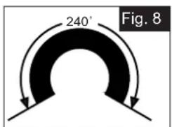
Fig.9
natural_image
Technical line drawing of a mechanical assembly with dimension label C (no text or symbols present)A: 6-3/4"
B: 10-1/2"
C: 6-1/2"
natural_image
Technical line drawing of a mechanical device with a rotating base and housing (no text or symbols)natural_image
Diagram showing a stepped structure with hatched shading, labeled Fig.2 (no text or symbols within the diagram itself)natural_image
Pure geometric diagram showing a right-angled corner with shaded triangular region (no text or symbols)natural_image
Diagram of a mechanical device with rotating arrows indicating motion, no text or symbols presentbar
| X-Axis | Value | |---|---| | 8.0' | 12.0' | | 10' | (unlabeled) | | 70' | (unlabeled) |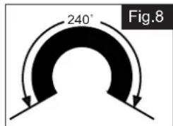
Fig.9
natural_image
Technical line drawing of a mechanical assembly with dimension label C (no text or symbols present)A : 17,15 cm (6-3/4 po)
B : 26,7 cm (10-1/2 po)
C : 16,5 cm (6-1/2 po)
- ASSEMBLY AND INSTALLATION INSTRUCTIONS
- WARNING: TO AVOID RISK OF ELECTRICAL SHOCK, BE SURE TO SHUT OFF POWER BEFORE INSTALLING OR SERVICING THIS FIXTURE.
- Hardware Package (included):
- Tools Needed:
- Important to Know:
- Features:
- Installation Steps
- Turn off the power at fuse or circuit box
- Turn on the power at fuse or circuit box
- Adjusting the Sensor Head:
- Sensitivity of Motion Sensor
- Adjusting the Light Head:
- 3 HOURS (3H) MODE (nighttime operation only)
- Manual Override (nighttime operation only)
- Customization Options:
- Shut-off Delay
- Notes:
- Year Limited Warranty
- In addition:
- FUNCIÓN Y OPERACIÓN
Brand : Vaxcel
Model : T0788
Category : Lighting