
AT72D - Electrical Transformer HONEYWELL - Free user manual and instructions
Find the device manual for free AT72D HONEYWELL in PDF.

| Brand | Honeywell |
| Model | AT72D |
| Product Type | Step-down electrical transformer |
| Primary Voltage | 120/240 V AC, 50/60 Hz |
| Secondary Voltage | 24 V AC |
| Output Power | 20 VA |
| Overload Protection | Energy limitation (thermal fuses on primary for 208/240 V) |
| Standards | NEMA DC-20 compliant, UL recognized, CSA certified, NEC class 2 (non-wet) and class 3 (wet) |
| Applications | 24 V AC control systems |
| Mounting Methods | On baseplate (screws in slots) or on plate (screws in baseplate slots); adaptable to 4x4 inch square or 4 inch octagonal junction box |
| Primary Connection | Two screw terminals (120 V) or three 229 mm conductors (240 V) |
| Secondary Connection | Two screw terminals |
| Installation Environment | Non-wet indoor or wet outdoor (class 3) |
| Maintenance and Cleaning | Clean with a dry cloth; do not use solvents or liquids; disconnect power before any maintenance |
| Safety | Disconnect power before installation; wiring according to local electrical codes; tape unused conductors |
| Included Accessories | Mounting plate (for mounting on electrical box) |
Frequently Asked Questions - AT72D HONEYWELL
User questions about AT72D HONEYWELL
0 question about this device. Answer the ones you know or ask your own.
Ask a new question about this device
Download the instructions for your Electrical Transformer in PDF format for free! Find your manual AT72D - HONEYWELL and take your electronic device back in hand. On this page are published all the documents necessary for the use of your device. AT72D by HONEYWELL.
USER MANUAL AT72D HONEYWELL
The AT20, AT40, AT72, AT87 and AT88 TRADELINE ^® Transformers are step-down transformers used primarily for powering 24 Vac control systems. They can be used in any 24 Vac application that does not exceed the transformer volt-ampere (VA) rating.
The TRADELINE® Transformers will replace all equivalent Honeywell and competitive transformers with similar primary voltage requirements, equal or smaller VA ratings and similar mounting configurations.
Transformer voltage ratings (primary and secondary), wiring connection type, and fusing are listed in Table 1.
The transformers are Underwriters Laboratories Inc. component recognized and Canadian Standards Association listed and meet NEC Class 2 not wet, Class 3 wet requirements as specified by NEMA Standard DC-20.
SPECIFICATIONS
Models:
See Table 1.
Table 1. Transformer Model and Electrical Specifications.
| Model | Primary Secondary Output at | 100 Percent Power Rating | Overload Protection | |||
| Voltage and Frequency | Wiring Connection Voltage | Voltage | Wiring Connection | |||
| AT20^a | 120 Vac, 50/60 Hz | Two 9 in. (229 mm) leadwires | 24 Vac Two 9 | in. (229 mm) leadwires | 20 VA Energy | Limitedc |
| AT40^a | 120 Vac, 50/60 Hz | 40 VA | ||||
| 240 Vac, 50/60 Hz | ||||||
| AT72D^a | 120 Vac, 50/60 Hz | two screw | terminals | |||
| 240 Vac, 50/60 Hz | Three 9 in. (229 mm) leadwires | |||||
| AT87A^a | 120 Vac, 50/60 Hz | Two 13 in. (330 mm) leadwires | 50 VA | |||
| 208 Vac, 50/60 Hz | ||||||
| 240 Vac, 50/60 Hz | ||||||
| AT88A 120 | Vac, 50/60 Hz Two | 12 in. (305 mm) leadwires | 24 Vac Two 1 | 2 in. (305 mm) leadwires | 75 VA Fuse in | secondary |
| 208/240 Vac, 50/60 Hz | ||||||
| 400 Vac, 50/60 Hz | ||||||
| 480 Vac, 50/60 Hz^b | ||||||
^a Transformer complies with 24 volt NEMA Standard DC-20.
^b Available with female quick-connect terminals on all leadwires.
^c Thermal fuses in primary on 208V/240V models for overload protection.
INSTALLATION
| A | B | C | D | |||||||
| in. | mm | in. | mm | in. | mm | in. | mm | in. | ||
| AT40C2 | -13/3261 | 7/822 | -3/4 | 442-3 | 16562 | -7/873 | ||||
| AT87A2 | -13/3261 | 1 | 251-3 | 4442 | -1/1652 | 3 | 76 |
When Installing This Product...
- Read these instructions carefully. Failure to follow them could damage the product or cause a hazardous condition.
- Check the ratings given in the instructions and on the product to make sure the product is suitable for your application.
- The installer must be a trained, experienced service technician.
- After installation is complete, check out product operation as provided in these instructions.

WARNING
Electrical Shock Hazard. Can cause severe injury, death or property damage.
Disconnect power supply before beginning installation to prevent electrical shock or equipment damage.
Mounting the AT20A and AT40A Transformer
- Mount the transformer to best suit the replacement application. The transformer may be mounted in one of three ways: a. Use bolts in slots for direct mounting (Fig. 1).
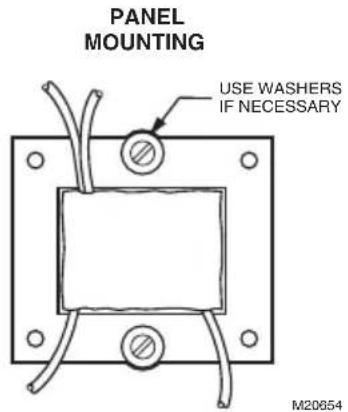
Fig. 1. Use bolts in slots for panel mounting.
b. Horizontal channel frame. Place frame over laminations as shown in Fig. 3 and bend tabs over to hold transformer securely in place. Mount transformer over 3/16 in. (5 mm) holes in mounting feet.
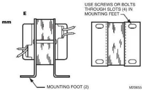
Fig. 2. Foot mounting (AT20C shown).
c. Vertical channel mounting. Place frame over laminations as shown in Fig. 3 and bend tabs over to hold transformer securely in place. Mount transformer through 3/16 in. (5 mm) holes in mounting feet.
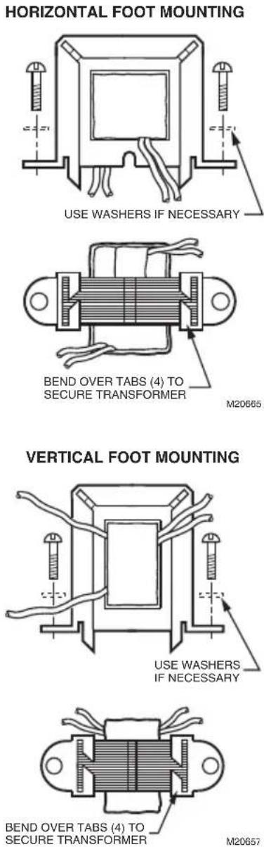
Fig. 3. Use horizontal channel frame for horizontal foot mounting; vertical channel frame for vertical foot mounting.
Mounting the AT72D Transformer.
Mount the transformer to meet the application. Use one of the methods illustrated. The transformer can be mounted in any position.
Foot Mounting.
- Discard mounting plate.
- Use screws or bolts through slots in mounting feet to fasten transformer to mounting surface (see Fig. 2).
Plate Mounting.
The mounting plate allows the transformer to be mounted on a 4 in. by 4 in. square or 4 in. octagonal junction box.
- Remove the large center knockout in the mounting plate (Fig. 6).
- Take transformer in one hand and mounting plate in the other hand. Keyhole slots on mounting plate should be up.
- Place large knockout in mounting plate over primary leadwires and end bell of transformer. The small tab on the bottom center of the plate fits into the slot in the transformer mounting feet (Fig. 7).
- Insert the mounting screw through the holes as illustrated.
- Secure the plate to the transformer. Do not overtighten.
Mounting plate to transformer (Fig. 4).
The plate can be mounted to the transformer in one of two positions:
a. at the clamp on primary end bell (transformer all above plate);
b. at the laminations (transformer 3/4 above plate. To mount the plate at clamp on primary end bell (transformer all above plate):
- Take mounting plate in one hand. Keep the key-hole slots up and the raised portion of the large center knockout toward you.
- Insert the primary leadwires through the center hole in the plate.
-
Fit the hole in the plate over the clamp attached to the end bell. Clamp screw must be turned almost completely out.
-
With the plate in place over the clamp, tighten the screw securely against the rim of the round hold See Fig. 5. Avoid damaging the leadwires with the screwdriver.
To mount the plate at the laminations (transformer 3/4 above the mounting plate:
- Remove the large center knockout in the mounting plate (see Fig. 6).
- Take the transformer in one hand. Clamp on end bell should face you.
- Take the mounting plate in the other hand. Key-hole slots should be up.
-
Place large knockout in mounting plate over primary leadwires and end bell. Small tab at the bottom of the center of the plate fits into the transformer mounting foot (Fig. 7). Insert mounting screw through holes as shown in Fig. 8.
-
Secure plate to transformer. Do not overtighten screw.
Mounting Transformer and Plate to Electrical Box
The mounting plate can be mounted to 4 in. x 4 in. boxes with regular and irregular spaced mounting holes, to 2 in by 4 in. boxes and to 4 in. octagonal boxes. See Fig. 9.
- Use the screws supplied with the electrical box.
- Place them through the proper mounting holes in the plate and secure the transformer and plate to the box.
- Punch out appropriate knockouts for plate mounting holes, if necessary.
NOTE: Transformer feet should always be outside of the junction box.
Clamp Mounting Using Junction Box Knockout
The transformer can also be clamp mounted using a junction box knockout, if desired. This mounting option does not require the use of the mounting plate. To mount the transformer within the knockout:
- Insert the primary leadwires and clamp and screw on transformer end bell through suitable 1/2 in. (13 mm) knockout in junction box. Clamp screw must be turned almost completely out in order to get clamp through knockout.
- Tighten clamp screw securely against rim of knockout. Avoid damaging the leadwires with the screwdriver.
PLATE MOUNTED AT CLAMP ON END BELL (ALL ABOVE PLATE MOUNTING)
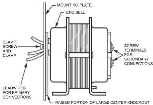
PLATE MOUNTED AT THE LAMINATIONS (3/4 ABOVE PLATE MOUNTING)
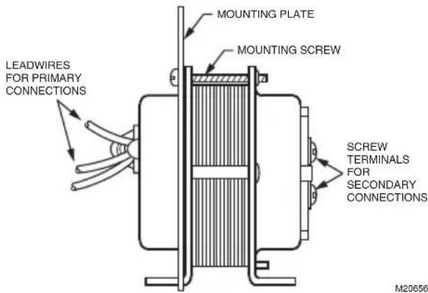
Fig. 4. Plate may be mounted to transformer in one of two positions (AT72D shown).
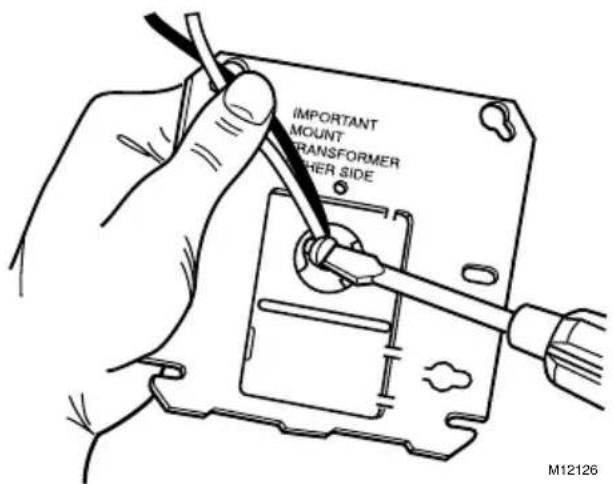
Fig. 5. Tighten clamp securely against rim of round hole.
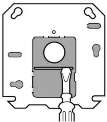
WITH RAISED PORTION OF KNOCKOUTS FACING YOU:
- PRY UP TOP SECTION OF LARGE KNOCKOUT BY INSERTING SCREWDRIVER FIRST AT ONE SIDE OF SLOT AND THEN AT THE OTHER SIDE.
natural_image
Pure technical diagram of a mechanical component without any text, numbers, or symbolsTHEN PRY UP BOTTOM SECTION OF KNOCKOUT.2.
natural_image
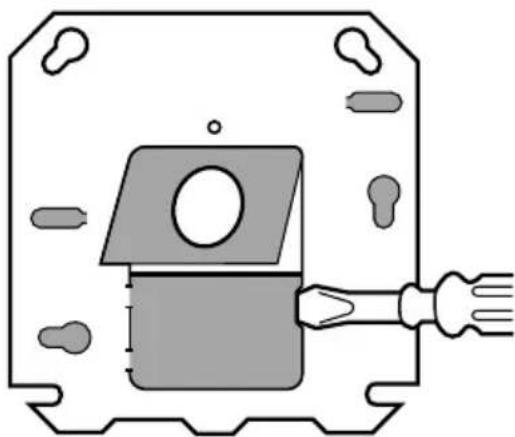
Pure technical diagram of a mechanical component with no text, numbers, or symbolsREMOVE BOTH SECTIONS OF KNOCKOUT WITH PLIERS.3.

SHADED AREAS REPRESENT KNOCKOUTS AND SCREW SLOTS USED WITH 2 X 4 INCH OR OCTAGONAL OUTLET BOXES.
M9188A
Fig. 6. Removing large center knockout.
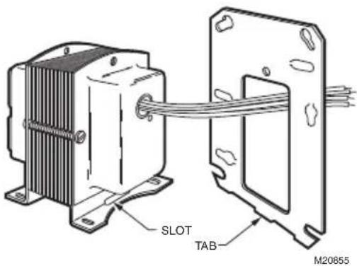
Fig. 7. Tab on mounting plate fits in slot on transformer mounting foot.
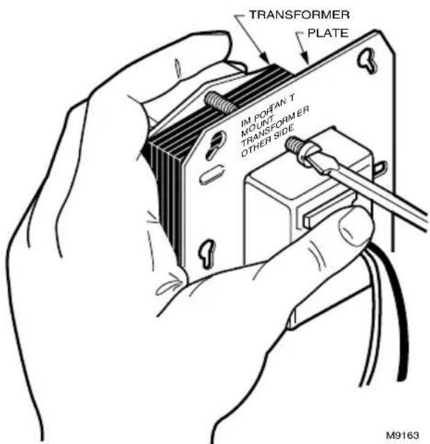
Fig. 8. Secure plate to transformer with mounting screw.
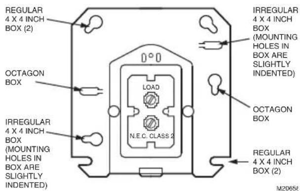
Fig. 9. Location of mounting holes.
Mounting the AT87 Transformer
Foot Mounting (Fig. 10)
Use screws or bolts through slots in the mounting feet to fasten the transformer to the mounting surface.
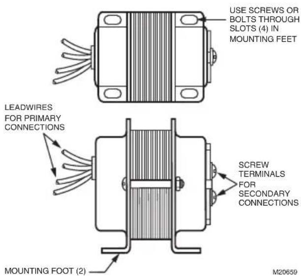
Fig. 10. Foot mounting of AT87 Transformer.
Plate Mounting
The mounting plate allows the transformer to be mounted on a 4 in. by 4 in. square or 4 in. octagonal junction box.
- Remove the large center knockout in the mounting plate (see Fig. 6).
- Take transformer in one hand and mounting plate in the other hand. Keyhole slots on mounting plate should be up.
- Place large knockout in mounting plate over primary leadwires and end bell of transformer. The small tab on the bottom center of the plate fits into the slot in the transformer mounting feet (see Fig. 7).
- Insert the mounting screw through the holes as illustrated (Fig. 8).
- Secure plate to transformer. Do not overtighten screw.
Mounting Transformer and Plate to Electrical Box.
The mounting plate can be mounted in 4 in. x 4 in. boxes with regular and irregular spaced mounting holes, and on 4 in. octagonal boxes (Fig. 9).
- Use the screws supplied with the junction box.
- Place the screws through the appropriate mounting holes in the plate and secure the transformer and plate to the box.
- Punch out appropriate knockouts for plate mounting holes, as necessary.
NOTE: Transformer should always be outside of the junction box.
Mounting the AT88 Transformer.
Use screws or bolts through slots in the mounting feet to fasten the transformer to the mounting surface. See Fig. 2.
WIRING
- Disconnect power supply before installing transformer. All wiring must comply with local electrical codes and ordinances. Tape all unused exposed leadwires separately.
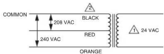
- Connect primary leadwires to line voltage power supply. See Fig. 11 through 13.
- Connect transformer secondary leadwires to 24 Vac control system.
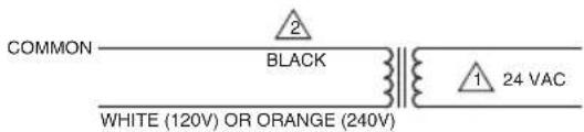
1 SECONDARY CONNECTIONS ARE BLUE AND YELLOW LEADWIRES.
2 BLACK IS COMMON WITH RESPECT TO THE TRANSFORMER WINDING ONLY AND NOT THE EXTERNAL CIRCUIT.
M20660
Fig. 11. AT20/AT40 Transformer schematic.
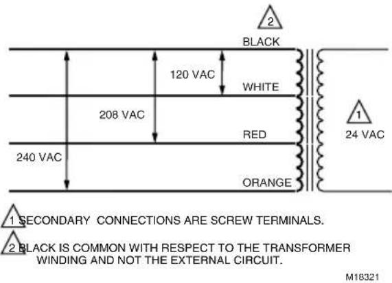
Fig. 12. AT72D, AT87A Transformer schematic.
1 SECONDARY CONNECTIONS ARE BLUE AND YELLOW LEADWIRES.
2 BLACK IS COMMON WITH RESPECT TO THE TRANSFORMER WINDING ONLY AND NOT THE EXTERNAL CIRCUIT.
M20661
Fig. 13. AT88 Transformer schematic.
CHECKOUT
After installation is complete, turn on power supply. Placed controlled equipment into operation and observe through at least one complete cycle. Make sure it functions as intended.
Honeywell
Transformateurs AT AT20, AT40, AT72D, AT87, AT88
NOTICE D'INSTALLATION
APPLICATION
natural_image
Pure technical diagram of a mechanical component without any text, numbers, or symbols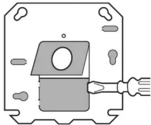
natural_image
Pure technical diagram of a mechanical component with no text, numbers, or symbols- ENLEVER LE DEUX PARTIES DE L'OUVERTURE DEFONÇABLE À L'AIDE DE PINCES.

PARTIES OMBRÉES: OUVERTURES DÉFONÇABLES ET FENTES POUR LES VIS À UTILISER AVEC LES BOÎTES DE 2 PO SUR 4 PO OU LES BOÎTES OCTOGONALES.
MF9188B
Honeywell International Inc.
1985 Douglas Drive North
Golden Valley, MN 55422
customer.honeywell.com
© 2016 Honeywell International Inc.
69-1641EF-01 M.S. Rev. 08-16