F1MSM30S1 - Oven Fulgor Milano - Free user manual and instructions
Find the device manual for free F1MSM30S1 Fulgor Milano in PDF.

User questions about F1MSM30S1 Fulgor Milano
0 question about this device. Answer the ones you know or ask your own.
Ask a new question about this device
Download the instructions for your Oven in PDF format for free! Find your manual F1MSM30S1 - Fulgor Milano and take your electronic device back in hand. On this page are published all the documents necessary for the use of your device. F1MSM30S1 by Fulgor Milano.
USER MANUAL F1MSM30S1 Fulgor Milano
natural_image
Simple geometric diagram with two black rectangles inside a larger rectangle (no text or symbols)F1SM24*2
F1SM30*4
F1MSM24*1
F1MSM30*1
ELECTRONIC OVENS
FOURS ELECTRONIQUES
EN
INSTRUCTIONS FOR INSTALLATION AND USE
FR
INSTRUCTIONS POUR L'INSTALLATION ET L'UTILISATION
Dear Customer,
we would like to thank you and congratulate you on your choice.
This new product has been carefully designed and built using top quality materials, and meticulously tested to ensure that it meets all your culinary requirements.
Please read and observe these simple instructions, which will enable you to achieve excellent results from the very first time you use it. This state-of-the-art appliance comes to you with our very best wishes.
THE MANUFACTURER
INDEX PAGE
| 1 - General Appliance and Oven Safety Precautions | 4 |
| 2 - General Appliance and Oven Safety Instructions | 5 |
| Safety for the Oven 5 | |
| The first time you use the oven 5 | |
| Respect for the environment 6 | |
| Control panel functions Function symbols on the selector 6 | |
| Instructions for use Conventional cooking 6 | |
| Fan cooking 7 | |
| Defrosting 7 | |
| Grill cooking 7 | |
| Cooling fan 7 | |
| Tangential cooling 7 | |
| Thermostat | 7 |
| 3 - Timer touch control | 8 |
| Setting the clock | 8 |
| Minute counter | 8 |
| Cooking time | 8 |
INDEX PAGE
| End of cooking time | 8 |
| Programming automatic cooking | 8 |
| Adjusting beep volume | 9 |
| Replacing the oven light | 9 |
| Removing the oven door | 9 |
| 4 - Installation instructions | 10 |
| Location of rating plate | 10 |
| Introduction | 10 |
| Tools you will need | 10 |
| Packaging | 10 |
| Power requirements | 10 |
| Choosing oven location | 10 |
| Steps for installation | 11 |
| Flush fitting | 11 |
| Electrical connections | 13 |
IMPORTANT: Save these instructions for the local electrical inspector use.
INSTALLER: Please leave this manual with owner for future reference.
OWNER: Please keep this manual for future reference.
THIS PRODUCT IS DESIGNED FOR DOMESTIC USE.
THE MANUFACTURER DECLINES ALL LIABILITY FOR DAMAGE TO PROPERTY OR PEOPLE DERIVING FROM INCORRECT INSTALLATION OR IMPROPER, ERRONEOUS OR UNSUITABLE USE.
THE APPLIANCE MUST NOT BE USED BY PEOPLE (INCLUDING CHILDREN) WITH PHYSICAL, SENSORIAL OR MENTAL IMPAIRMENTS, OR BY PEOPLE WITHOUT THE NECESSARY EXPERIENCE OR KNOWLEDGE, UNLESS THEY ARE SUPERVISED OR INSTRUCTED IN THE USE OF THE APPLIANCE BY A PERSON RESPONSIBLE FOR THEIR SAFETY.
CHILDREN MUST BE SUPERVISED TO ENSURE THAT THEY DO NOT PLAY WITH THE APPLIANCE.

IMPORTANT INSTRUCTION
Please read all instructions before using this appliance.


WARNING
When properly cared for, your new FULGOR oven has been designed to be a safe, reliable appliance. Read all the instructions carefully before using this oven.
These precautions will reduce the risk of burns, electric shock, fire, and injury to persons. When using kitchen appliances, basic safety precautions must be followed, including the following:

CAUTION
- Do not store items of interest to children above the oven. If children should climb onto the appliance to reach these items, they could be seriously injured.
This appliance must be properly installed and grounded by a qualified technician. Connect only to a properly grounded outlet. See "grounding Instructions" found in the Installation Instructions.
- This appliance should be serviced only by a qualified service technician. Contact the nearest authorized service center for examination, repair or adjustment.
- Do not repair or replace any part of the oven unless specifically recommended. For servicing contact an authorized servicer.
- Do not operate this appliance if it is not working properly or if has been damaged, until an authorized servicer has examined it.
- Install or locate this appliance only in accordance with the Installation Instructions.
- Use this oven only as intended by the manufacturer. If you have any questions, contact the manufacturer.
- Do not cover or block any openings on this appliance.
- Use this appliance only for its intended use as described in this manual. Do not use corrosive chemicals, vapors, or nonfood products in this appliance. This type of oven is specifically designed to heat or cook. It is not designed for industrial or laboratory use. The use of corrosive chemicals in heating or cleaning will damage the appliance.
- In the event that personal clothing or hair catches fire, DROP AND ROLL IMMEDIATELY to extinguish flames.
- Do not allow children to use this appliance unless closely supervised by an adult. Children and pets should not be left alone or unattended in the area where the appliance is in use. Never allow children to sit or stand on any part of the oven.
To reduce the risk of fire in the oven cavity:
- Do not store flammable materials in or near the oven.
- Do not extinguish a grease fire using water. Smother fire or use a dry chemical or foam -type extinguisher.
- It is highly recommended that a fire extinguischer be readily available and highly visible next to any cooking appliance.
- Do not overcook food. Carefully attend oven if paper, plastic or other combustible materials are placed inside the oven.
- Do not use the cavity for storage purposes. Do not leave paper products, cooking utensils or food in the cavity when not being used.
- If materials inside the oven should ignite, keep oven door closed. Turn oven off and disconnect the circuit at the circuit breaker box.
- Do not block any vent openings.
- Make sure the blower fan is running whenever the oven is in operation. If the fan does not work, do not use the oven. Call an authorized service center.
- Never use the oven to warm or heat a room. This can damage the oven parts.
- For personal safety, wear proper clothing. Loose fitting or garments with hanging sleeves should never be worn while using this appliance.

IMPORTANT INSTRUCTION
Please read all instructions before using this appliance.

Safety for the Oven
- Tie long hair so that it doesn't hang loose.
- Do not touch elements or interior surfaces of oven.
- The heating elements may be hot even if they are dark in color. The interior surface of an oven become hot enough to cause burns.
- During and after use, do not touch or let clothing or other flammable materials contact the heating elements or the interior surfaces of the oven until they have had sufficient time to cool. Other surfaces of the appliance my become hot enough to cause burns - among these surfaces are (identification of surface - for example, oven vent openings and surfaces near these openings, oven doors, and windows of oven doors).
- The trim on the top and sides of the oven door my become hot enough to cause burns.
- Take care when opening the door. Open the door slightly to let hot air on steam escape before removing or replacing food.
- Do not heat unopened food containers. Build-up of pressure may cause the container to burst and cause injury.
- Always place oven racks in desired location while oven is cool. If a rack must be moved while oven is hot, do not let pot holder contact the got heating elements.
- Use only pot holders. Moist or damp pot holders on hot surfaces may result in burns from steam. Do not let pot holder touch hot heating elements. Do not use a towel or
- other bulky cloth.

WARNING
The California Safe Drinking Water and Toxic Enforcement Act requires businesses to warn customers of potential exposure to substances which are known by the State of California to cause cancer or reproductive harm.
Do not allow aluminum foil or meat probe to contact heating elements.
The first time you use the oven
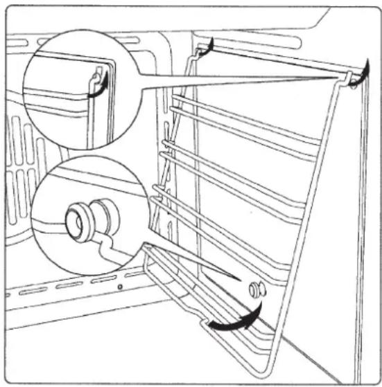
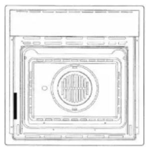
Clean the oven thoroughly with soapy water and rinse well. To remove the lateral frames from smooth-walled ovens, proceed as shown in the figure.
Operate the oven for about 30 minutes at maximum temperature to burn off all traces of grease which might otherwise create unpleasant smells when cooking.
natural_image
Technical line drawing of a refrigerator interior showing structural components and airflow direction (no text or symbols)IMPORTANT: As a safety precaution, before cleaning the oven, always disconnect the plug from the power socket or the power cable from the oven. Do not use acid or alkaline substances to clean the oven (lemon juice, vinegar, salt, tomatoes etc.). Do not use chlorine based products, acids or abrasive products to clean the painted surfaces of the oven.
DO NOT USE STEAM CLEANERS
Respect for the environment
The documents accompanying this appliance consist of bleached paper, without chlorine or recycled paper for the purpose of contributing to protection of the environment.
The packing materials are conceived so as not to damage the environment; they can be recovered or recycled as they are ecological products.
Recycling the packing will contribute to a saving of raw materials and reduction in the volume of industrial and domestic refuse.
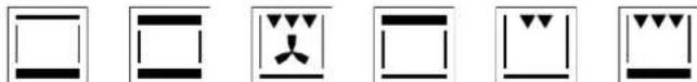
Control panel functions Function symbols on the selector
| ICON OVEN 24" | |
 | Oven light (stays on while oven is in use). |
 | Top and bottom heating elements. Thermostat setting from 120° F (50°C) to MAX. |
 | Top and bottom heating elements with fan. Thermostat setting from 120° F (50°C) to MAX. |
 | Lower heating coil with fan Regulation of the thermostat from 120° F (50°C) to MAX |
 | Top heating element (Broil small) |
 | Double top heating element (large area grill) with fan. Thermostat setting from 120° F (50°C) to MAX. |
 | Circular heating element with fan. Thermostat setting from 120° F (50°C) to MAX. |
| ICON OVEN 30" | |
 | Oven light (stays on while oven is in use). |
 | Only fan (No heating element in use). |
| [8TBW] | Top and bottom heating elements. Thermostat setting from 120°F (50°C) to MAX. |
 | Top and bottom heating elements with fan. Thermostat setting from 120°F (50°C) to MAX. |
 | Circular heating element with fan. Thermostat setting from 120°F (50°C) to MAX. |
 | Double top heating element (large area grill) with fan. Thermostat setting from 120°F (50°C) to MAX. |
 | Top heating element (Broil small) |
 | Top heating element (Broil Double) |
Instructions for use Conventional cooking
natural_image
Six black-and-white schematic symbols arranged in two rows, each containing rectangular blocks and a central icon (no text or labels)Conventional cooking uses top and bottom heat to cook a single dish. Place the food in the oven only once cooking temperature has been reached, i.e. when the heating indicator goes out.
If you want to increase top or bottom temperature towards the end of the cooking cycle, set the temperature control to the right position. It is advisable to open the oven door as little as possible during cooking.
natural_image
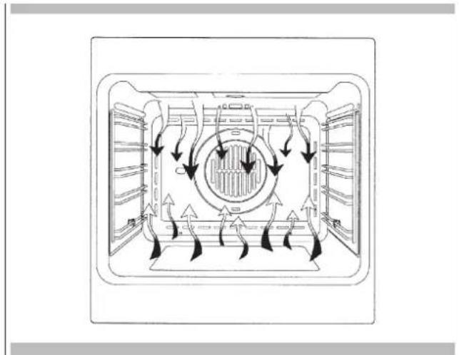
Diagram of a refrigerator interior showing airflow patterns around the central chamber (no text or labels)Fan cooking


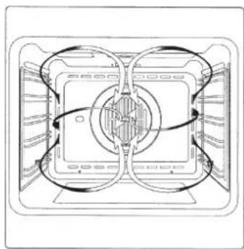
For this type of cooking a fan positioned at the back allows the circulation of hot air inside the oven, creating uniform heat. In this way cooking is more rapid than conventional cooking. It is a suitable method for cooking dishes on more than one shelf, especially when the food is of different types (fish, meat etc.).
Defrosting

By selecting one of the fan cooking functions and setting the thermostat to zero, the fan allows cold air to circulate inside the oven. In this way frozen food can be rapidly defrosted. It is not essential to pre-heat the oven, but you are advised to do so when cooking pastries.
natural_image
Technical line drawing of a mechanical or electrical component with no visible text or symbolsGrill cooking


Use the grill to grill or brown foods. Some ovens may be equipped with an electric motor, spit and skewers for turning on the spit. Place the shelf with the food to be cooked in the 1st or 2nd position from the top.
Pre-heat the oven for 5 minutes. Turn the thermostat to a temperature between 120^ F (50°C) and 390^ F (200°C).
Cooling fan
natural_image
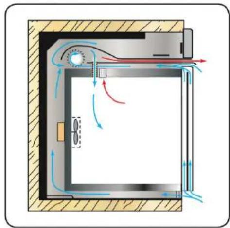
Cross-sectional diagram of a door with airflow indicators and directional arrows (no text or symbols)Tangential cooling
A forced air circulation system which contributes to reducing the heat exchange temperature in the front and lateral areas of the ovens.
Thermostat 10 The fan is positioned on the upper part of the oven and creates a vortex of cooling air on the inside of the appliance and through the oven door.
It is turned on when the temperature of the outer shell of the oven reaches 140^ F ( 60^ C).
By switching on the oven with the thermostat at 390^ F ( 200^ C) the fan starts working after approx. 10 min.
It is turned off when the temperature of the outer shell of the oven drops below 140^ F ( 60^ C).
By switching off the oven with the thermostat at 390°F (200°C) the fan stops working after approx. 30 min.
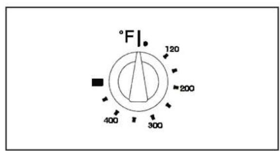
Thermostat
Use the thermostat to set the cooking temperature you need. The thermostat can be adjusted from 120°F (50°C) to 480°F (250°C).
text_image
°F 120 200 400 300Setting the clock
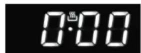
Fig. 1
"Auto" and "0:00" will start flashing when the unit is switched on for the first time. To set the clock, press the central button for about 3 seconds. When 📋 appears, press "+" or "-" to set the correct time.
Wait until a beep tells you that the clock has been set (figure 1). To set the time at a later stage, press "+" and "-" together for 3 seconds and then adjust the clock as described above.
Minute counter
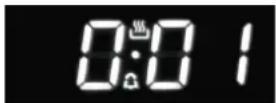
Fig. 2
As this minute counter does not control the oven, when it finishes counting the oven will continue to work.
To set, press the central button for 3 seconds until 🔒 appears (figure 2).
Press "+" and "-" to set the required time. To set the minute counter at a later stage, press the central button for 3 seconds and adjust as described above.
The minute counter beeps when it finishes counting. To disable it, press any button.
Cooking time

Fig. 3
This is a semi-automatic cooking function. It can be used to set cooking times.
Press the central button for 3 seconds. Then press it again until "dur" appears (figure 3). Press "+" and "-" to set the required cooking time.
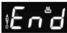
End of cooking time
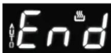
Fig. 4
The end of cooking time can also be set. Press the central button for 3 seconds. Press the central button twice consecutively and wait for "End" to appear (figure 4). Press "+" and "-" to set the required end of cooking time.
The oven will work in the set mode and at the set temperature until the end of cooking time.
Programming automatic cooking
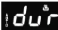
Fig. 5
Cooking function with set times. Press the central button for 3 seconds.
Then press it again until "dur" appears. Press "+" and "-" to set the required cooking time. Wait a few seconds for the setting to be memorised. Press the central button for 3 seconds.
Press it another two times and wait for "End" to appear (figure 4). Press "+" and "-" to set the required end of cooking time.
E.g.:
Current time: 12.30
Cooking time: 10 minutes
End of cooking time: 14.00
The oven will start cooking at 13.50 (14.00 less 00.10) at the set temperature and in the set mode and will stop at 14.00.
The oven will beep when it stops cooking.
To disable it, press any button.
Adjusting beep volume


Fig. 6
To adjust beep volume, press "+" and "-" together. Then press the central button and wait for "ton1" (high volume) to flash.
Press "-" to select "ton2" (medium volume) or "ton3" (low volume).
Press the central button to set the selected volume.
Replacing the oven light
IMPORTANT:
The oven light must have these precise features:
a) it must be able to resist high temperatures (up to 570° F (300° C))
b) power supply: see V/Hz indicated on data plate.
c) power 25W.
d) E9 connection. Before proceeding, disconnect the appliance from the main electricity supply.
- To prevent damage, place a tea cloth in the oven;
- unscrew the glass cover of the light;
- remove the old light bulb and replace it with the new one;
- put back the glass cover and remove the tea cloth;
- connect the appliance to the main electricity supply;
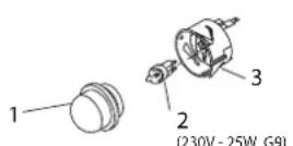
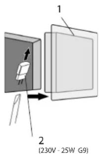
text_image
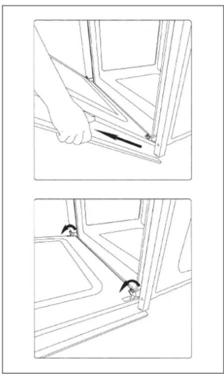
1 2 (230V - 25W G9)Removing the oven door
The oven door can be removed quickly and easily. To do so, proceed as follows:
- Open the door fully.
- Lift the two levers shown in fig.
- Close the door as far as the first stop (caused by the raised levers).
- Lift the door upwards and outwards to remove it from its mountings.
To replace fit the door, fit the hinges in their mountings and lower the two levers.
natural_image
Technical line drawing showing two steps of a hand holding a tool, with no visible text or symbolsLocation of rating plate
natural_image
Technical line drawing of a square enclosure with a circular vent and internal structure (no text or symbols)
WARNING
If the information in this manual is not followed exactly, a fire or explosion may result causing property damage, personal injury or death.
Introduction
Please read these instruction COMPLETELY AND CAREFULLY. They will save you time and effort and help to ensure optimum oven performance. Be sure to observe all WARNINGS.
These installations are intended for use by a qualified installer. In addition to these instructions, the oven shall be installed:
- In the United States, in accordance with the National Electric Code/State and Municipal codes and/or local codes.
- In Canada, in accordance with Canadian Electric Code C22.1-latest edition/Provincial and Municipal codes and/or local codes.
These shall be carefully followed at all times.
NOTE: IF INSTALLING YOUR OVEN IN CANADA PLEASE CHECK TO MAKE SURE THAT YOU HAVE A MODEL WITH THE CANADIAN LISTING.

Intertek
MARK, AS SHOWN ABOVE:
Mark as shown above means the oven complies with both US and CANADIAN Standards.
Tools you will need
The following tools are needed to install your new oven:
- Pencil
- Phillips screwdriver
- Level
• Wire cutters and wire stripper - Hand or saber saw
- 1" (2,5 cm) Hole saw
- Drill and drill bit
• Safety gloves and goggles - Volt meter (0-250VAC)
- Tape measure and straight edge or rules
Packaging
Remove all tape and packaging before using the oven.
Destroy the packaging after unpacking the oven following the rules in force in your town. Never allow children to play with packaging material.
Power requirements
The oven must be supplied with the proper voltage and frequency. The oven is manufactured to be connected to a three-wire, single phase, 120/240V, 60 Hz AC electrical supply on a separate circuit fused in both sides of the line. A circuit breaker or time delay fuse sized not to exceed the circuit rating of the appliance specified on the rating plate located on the frame behind the door of the oven is recommended. The oven must be supplied with copper or aluminum wires. If aluminum wire is provided to connect oven to branch circuit, UL listed connectors for joining copper and aluminum must be used. Follow instructions provided with connectors. If is recommended that you have the electrical wiring and hook-up of your oven performed by a qualified electrician. After installation is complete have the electrician show you where the main disconnect is and which of the circuit breakers/fuses are for the oven.
Choosing oven location
Carefully select the location where the oven will be placed.
The oven should be located for convenient use in the kitchen, but away from strong drafts. Strong drafts may be caused by open doors or windows, or by heating and/or air conditioning vents or fans. Make sure that electrical power can be provided to the location selected.
Steps for installation
The following pages provided the necessary information for proper installation of the oven and are arranged as follows:
- Technical Data
• Installation Cutout Dimensions, Required Clearances and Mounting instructions for:
- Under counter installation, Single Oven
- Wall installation, Single Oven
Flush fitting
- Electrical supply and Wiring Requirements, programming not required if connecting to 120/208 Volt circuit. Electrical Connections for 3-wire or 4-wire Branch Circuit.
- Final Checklist.
The oven can be installed under a work top or in a cooking column. Figure shows the installation dimensions.
Make sure that surrounding materials are heat resistant. Align the oven centrally with respect to the side walls of the units surrounding it and fix it in place with the screws and bushings provided.
"CUTOUT DIMENSION 24" (60CM)"
| Ltr. | DIMENSION | inch cm | |
| A Cutout Width | 22 1/16" | 56cm | |
| B | Cutout Dept h (min) | 22 1/16" | 56cm |
| C Cutout Height | 23" | 58,5cm | |
| D Floor Bottom of Cutout | 34" | 86,5cm | |
| E Minimum Spacing | 1/2" | 1,3cm | |
| FLUSH INSTALLATION | |||
| F | Cutout Width | 23 5/8" | 60 cm |
| G | Cutout Height | 24 1/64" | 61 cm |
| H | Mounting strips | 19/32" | 1,5 cm |
| I | Mounting strips | 19/32" | 1,5 cm |
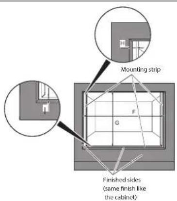
text_image
Mounting strip Finished sides (same finish like the cabinet)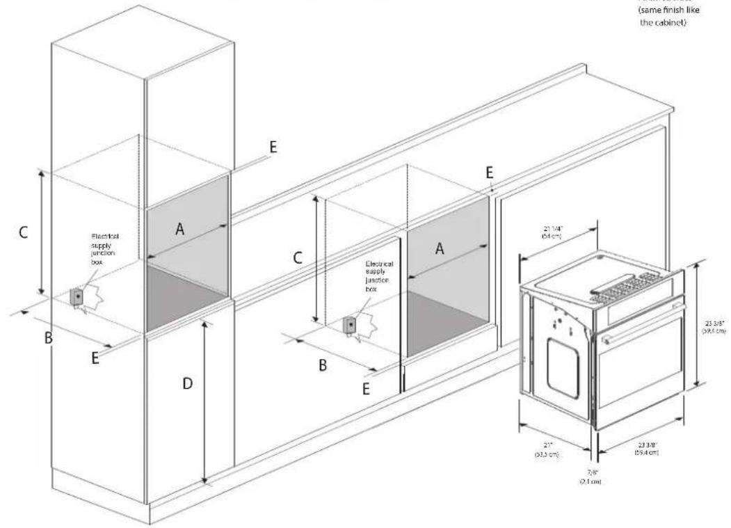
text_image
(same finish like the cabinet) Electrical supply junction box E C B E A D C B E Electrical supply junction box A E 21.1/4" (0.4 cm) 23.3/8" (0.9 x 0.5 cm) 21" (0.3 cm) 23.3/8" (0.9 x 0.5 cm) 7/8" (0.1 cm)"CUTOUT DIMENSION 30" (75CM)"
| Ltr. | DIMENSION | inch cm | |
| A Cutout Width | 28" | 71cm | |
| B | Cutout Dept h (min) | 22 1/16" | 56cm |
| C Cutout Height | 23" | 58,5cm | |
| D Floor Bottom of Cutout | 34" | 86,5cm | |
| E Minimum Spacing | 1/2" | 1,3cm | |
| FLUSH INSTALLATION | |||
| F | Cutout Width | 30 1/8" | 76,5 cm |
| G | Cutout Height | 24 1/64" | 61 cm |
| H | Mounting strips | 19/32" | 1,5 cm |
| I | Mounting strips | 19/32" | 1,5 cm |
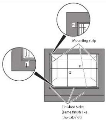
text_image
Mounting strip G F Finished sides (same finish like the cabinet)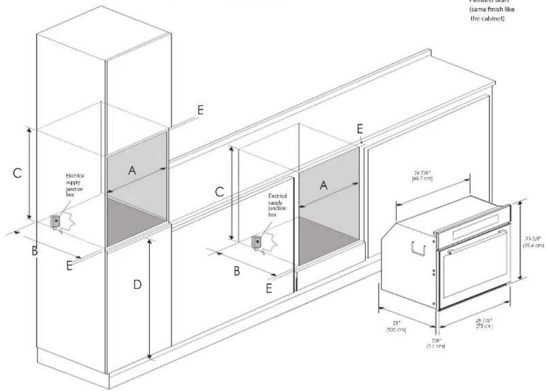
text_image
(same finish like the cabinet) Electrical supply junction box Electrical supply junction box 24.7/8" [46.2 cm] 23.3/8" (25.4 cm) 21" (550 cm) 7/8" (2.1 cm)Electrical connections
Be sure your appliance is properly installed and grounded by a qualified technician. Ask your dealer to recommend a qualified technician or an authorized repair service.
This appliance is manufactured is with a green GROUND wire connected to the oven body. After making sure that the power has been turned off, connect the flexible conduit from the oven to the junction box using a U.L. listed conduit connector. Figures A and B and the instructions provided below present the most common way of connecting the ovens.
Your local codes and ordinance, of course, take precedence over these instructions. Complete electrical connections according to local codes and ordinance.

WARNING
Risk of Electric Shock, frame grounded to neutral of appliance through a connection.
Ground through the neutral conductor is prohibited for new branch-circuit installation (1996 NEC); mobile homes; and recreation vehicles, or in an area where local codes prohibit grounding through the neutral conductor. For installations where grounding through the neutral conductor. For installations where grounding through the neutral conductor is prohibited:
- Disconnect the ground from the neutral at free end of conduit;
- Use grounding terminal or lead to ground unit; and usual procedure.
3-Wire branch circuit (for US only)
Refer to Figure A, where local codes allow the connection of GROUND wire from the oven to the branch circuit NEUTRAL wire (gray or white colored wire):
- If local codes permit, connect the green GROUND wire from the oven and the white wire from the oven to the branch circuit NEUTRAL wire (gray or white colored wire).
- Connect the red and black leads from the oven to the corresponding leads in the junction box.
A
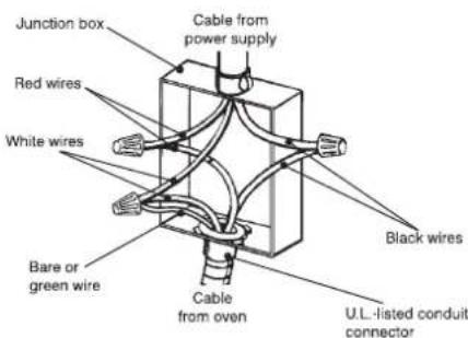
text_image
Junction box Red wires White wires Bare or green wire Cable from power supply Black wires Cable from oven U.L.-listed conduit connector4-Wire branch circuit (for US and CANADA)
Refer to Figure B:
- Connect the green GROUND wire from the oven to the GROUND wire in the junction box (bare or green colored wire).
- Connect the red and black leads from the oven to the corresponding leads in the junction box.
- Connect the white wire from the oven to the NEUTRAL (gray or white) wire in the junction box.
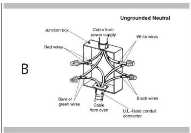
text_image
B Junction box Red wires Cable from power supply White wires Bare or green wires Cable from oven Black wires U.L.-listed conduit connector Ungrounded NeutralCher Client,
natural_image
Technical line drawing of a refrigerator interior showing structural components and ventilation slots (no text or symbols)natural_image
Six black-and-white schematic symbols arranged horizontally, each containing a rectangular box with a central arrow or symbol (no text or labels)natural_image
Diagram of airflow or heat transfer through a rectangular chamber with circular vent and fan-like structures (no text or labels)Cuisson ventilee


natural_image
Technical line drawing of a mechanical or electronic component with no visible text or symbolsCuisson au gril


natural_image
Cross-sectional diagram of a door with airflow indicators and internal components (no text or symbols)natural_image
Technical line drawing showing two steps of a hand holding a bracket, with no visible text or symbolsnatural_image
Technical line drawing of a square enclosure with a circular vent and internal structure (no text or symbols)
AVERTISSEMENT
"DIMENSION DE DÉCOUPE 24" (60 CM)"