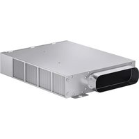
AA413723 - Oven GAGGENAU - Free user manual and instructions
Find the device manual for free AA413723 GAGGENAU in PDF.


| Product type | Recirculation kit with activated carbon filter for oven |
| Brand | Gaggenau |
| Model | AA413723 |
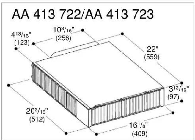
| Dimensions (W x D x H) | 512 x 559 x 123 mm |
| Weight | Approximately 5 kg |
| Power supply | Connection to the base fan (not specified) |
| Main functions | Air recirculation, odor filtration with activated carbon |
| Maintenance and cleaning | Replacement of activated carbon filter every 12 to 18 months |
| Safety | Minimum distance of 150 mm in front of the air outlet |
| Spare parts and repairability | Activated carbon filter (not included), flexible duct AD 413 722 (optional) |
| General information | Under-cabinet installation, requires an air outlet in the base panel |
Frequently Asked Questions - AA413723 GAGGENAU
User questions about AA413723 GAGGENAU
0 question about this device. Answer the ones you know or ask your own.
Ask a new question about this device
Download the instructions for your Oven in PDF format for free! Find your manual AA413723 - GAGGENAU and take your electronic device back in hand. On this page are published all the documents necessary for the use of your device. AA413723 by GAGGENAU.
USER MANUAL AA413723 GAGGENAU
Installation instructions....1
Instructions d'installation....6
Recirculation kit with filter
This indicates that death or serious injuries may occur as a result of non-observance of this warning.
CAUTION
This indicates that minor or moderate injuries may occur as a result of non-observance of this warning.
NOTICE: This indicates that damage to the appliance or property may occur as a result of non-compliance with this advisory.
Note: This alerts you to important information and/or tips.
Before you begin
IMPORTANT: Observe the Safety and Installation Instructions included with the Recirculation Blower AR 413 722.
Tools and parts needed
- Screwdriver Torx T20
Pencil - Drill with 14'' (6 mm) bit
• Phillips head screwdriver
Jigsaw - Tape Measure
- Tin snips
Note: Additional materials may be necessary for installation in solid surface countertops. Contact the countertop manufacturer.
Parts included
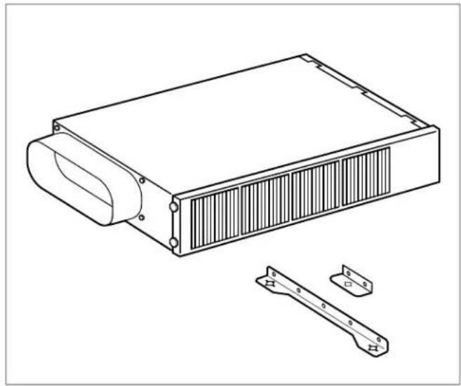
natural_image
Technical line drawing of a rectangular electronic device with ventilation grilles and two separate mounting brackets (no text or symbols)Required accessory (please order separately)
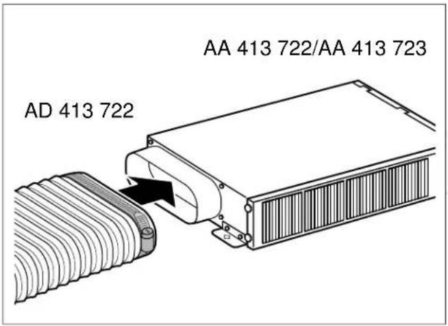
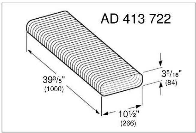
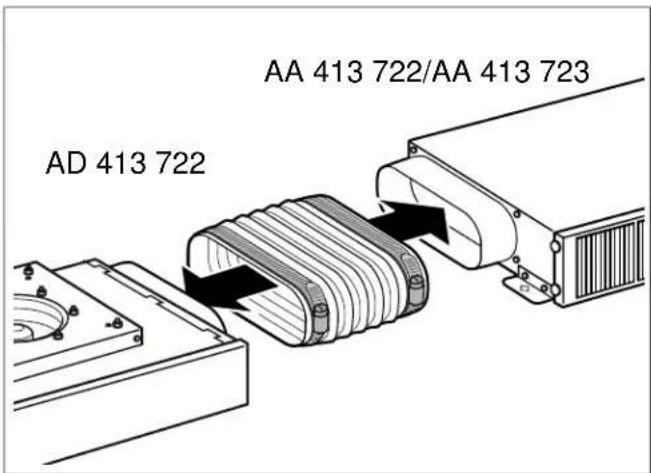
AD 413 722 Aluminum flex duct
Note: The AA 413 722 and AA 413 723 recirculation kits with filter can only be operated with the aluminum flex duct AD 413 722 (optional accessory, please order separately).
Appliance dimensions
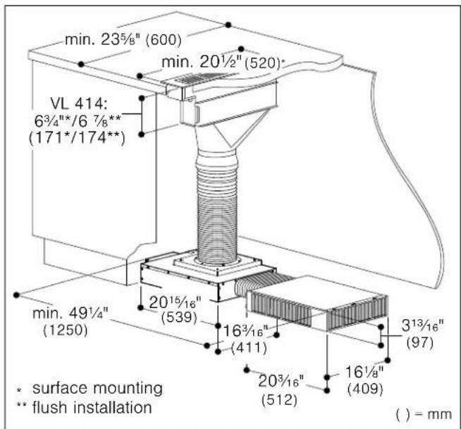
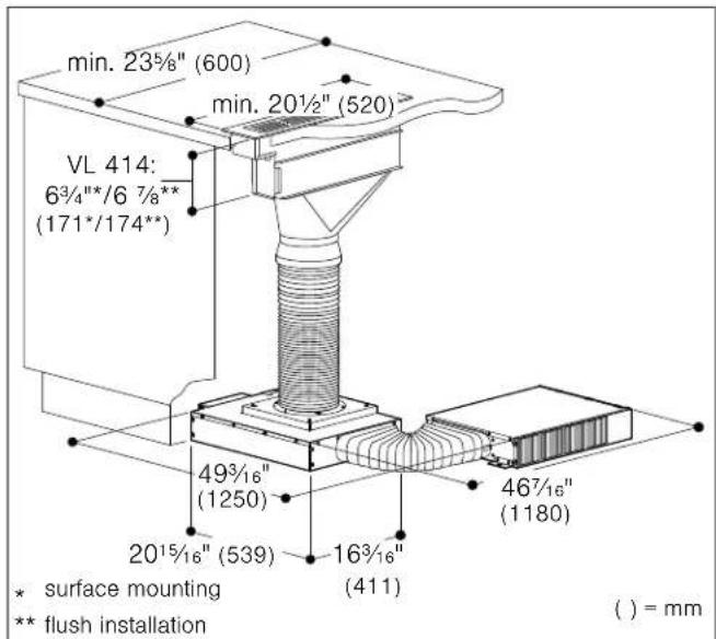
Dimensions for wall installation
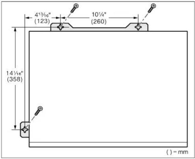
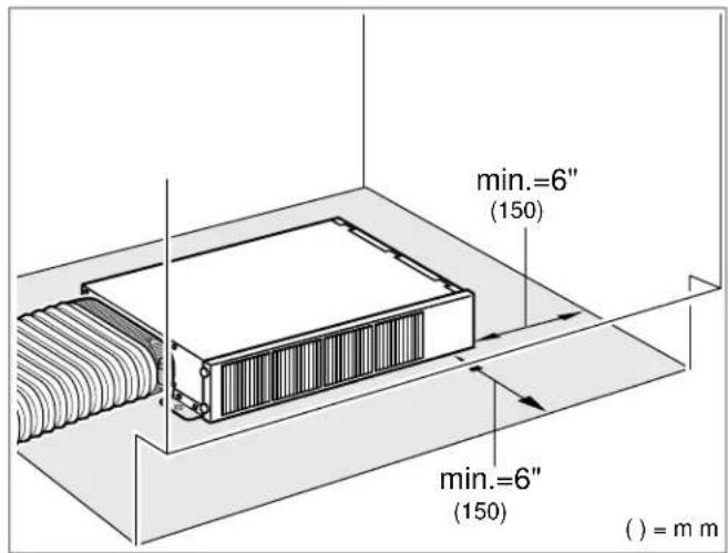
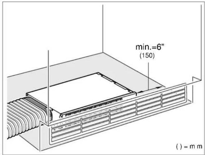
Minimum distances for air outlet
Heed minimum distance of 6" (150 mm) between air outlet and toe-kick panel and air outlet and side wall.
Installation behind closed length of the toe-kick panel:
Installation behind toe-kick panel with air grille:
Preparing kitchen units
Exhaust opening in the toe-kick panel
Provide an air outlet in the toe-kick panel, minimum cross-section approx. 120 square inches (720 cm ^4 ).
Make the exhaust opening in the toe-kick panel as large as possible in order to keep drafts and noise to a minimum.
Note: The toe-kick panel must be removable, or an opening of at least 23 58 " x 4" (600 x 100 mm) must be provided so that the filter can be changed.
Installation
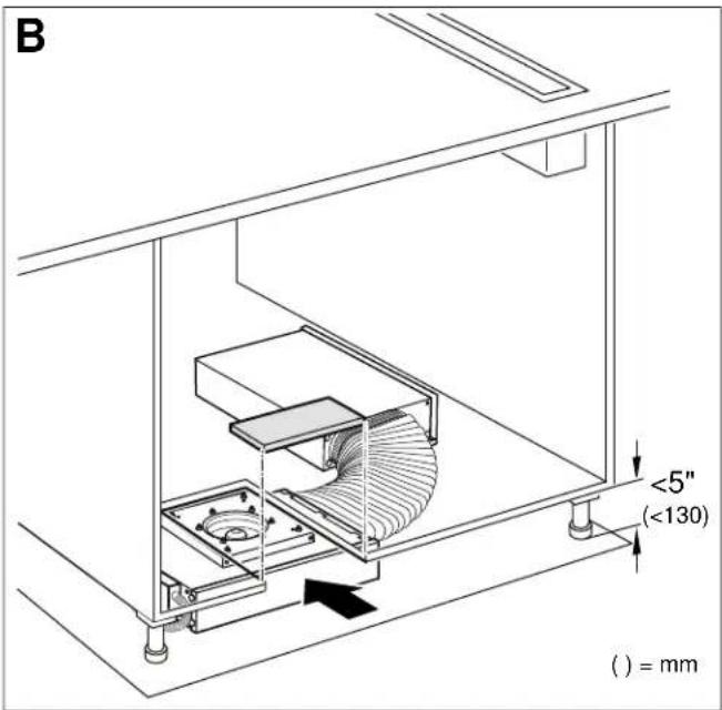
1 Shorten the connecting hose to the required length. Mount the ends on the filter unit and base fan.
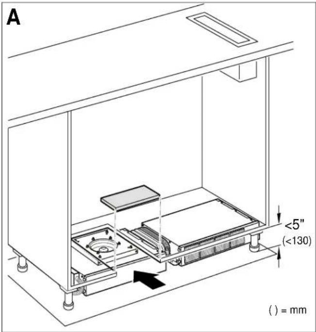
2 Push the appliances under the cupboard side by side or arrange diagonally (see Fig. A and B). Do not bend or pinch the power cable, or route it over sharp edges.
Note: The appliances have rubber feet, fastening not required.
Changing the activated-carbon filter
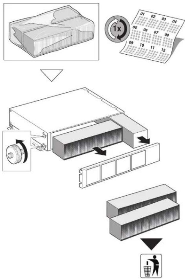
To guarantee that odors are discharged, the activated-carbon filter must be changed every 12 - 18 months.
The activated-carbon filter is available from specialist retailers, from customer service or from the Online Shop.
Note: The activated-carbon filter cannot be cleaned or activated again.
1 Remove the base panel.
2 Loosen the knurled screws on the side. Remove the grating.
3 Pull out the old activated-carbon filter toward the front.
4 Insert the new activated-carbon filter.
5 Replace the grating, tighten the knurled screws.
6 Replace the base panel.
flowchart
graph TD
    A["Raw Material"] --> B["Recycle"]
    B --> C["Add 1x Multiplier"]
    C --> D["Product Collection"]
    D --> E["Finished Product"]
    style A fill:#f9f,stroke:#333
    style B fill:#ccf,stroke:#333
    style C fill:#cfc,stroke:#333
    style D fill:#fcc,stroke:#333
    style E fill:#ffc,stroke:#333
natural_image
Technical line drawing of a rectangular electronic device with ventilation slots and a separate bracket (no text or symbols)flowchart
graph TD
    A["Raw Material Inspection"] --> B["Recycle with Container"]
    B --> C["Recycle with Box"]
    C --> D["Recycle with Panel"]
    D --> E["Recycle with Box"]
    E --> F["Recycle with Basket"]
    F --> G["Final Disposal"]
natural_image
Technical line drawing of a rectangular electronic device with internal grating and two separate mounting brackets (no text or symbols)flowchart
graph TD
    A["Raw Material"] --> B["Recycle"]
    B --> C["Add 1x Multiplier"]
    C --> D["Product Collection"]
    D --> E["Recycle Bin"]
    E --> F["Recycle Bin"]
    F --> G["Recycle Bin"]
    G --> H["Recycle Bin"]
    H --> I["Recycle Bin"]
    I --> J["Recycle Bin"]
    J --> K["Recycle Bin"]
    K --> L["Recycle Bin"]
    L --> M["Recycle Bin"]
    M --> N["Recycle Bin"]
    N --> O["Recycle Bin"]
    O --> P["Recycle Bin"]
    P --> Q["Recycle Bin"]
    Q --> R["Recycle Bin"]
    R --> S["Recycle Bin"]
    S --> T["Recycle Bin"]
    T --> U["Recycle Bin"]
    U --> V["Recycle Bin"]
    V --> W["Recycle Bin"]
    W --> X["Recycle Bin"]
    X --> Y["Recycle Bin"]
Gaggenau
BSH Home Appliance Corporation
1901 Main Street, Suite 600
Irvine, CA 92614
+1.877.442.4436
USA
www.gaggenau-usa.com
© 2015 BSH Home Appliances

Brand : GAGGENAU
Model : AA413723
Category : Oven