P250068 - Fan Progress Lighting - Free user manual and instructions
Find the device manual for free P250068 Progress Lighting in PDF.


User questions about P250068 Progress Lighting
0 question about this device. Answer the ones you know or ask your own.
Ask a new question about this device
Download the instructions for your Fan in PDF format for free! Find your manual P250068 - Progress Lighting and take your electronic device back in hand. On this page are published all the documents necessary for the use of your device. P250068 by Progress Lighting.
USER MANUAL P250068 Progress Lighting
BELVA Ceiling Fan Installation Manual
natural_image
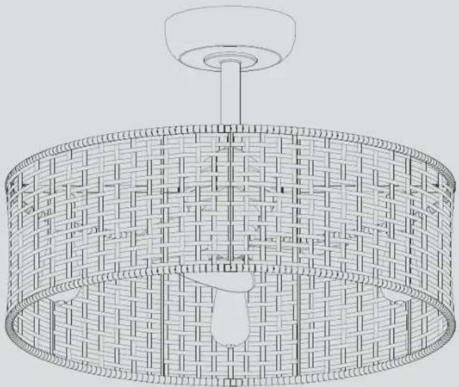
Line drawing of a woven basket with a top lamp and central hub (no text or symbols)93138712_B
P250068
Limited Lifetime Warranty
Progress Lighting fan motors are warranted to the original purchaser to be free of electrical and/or mechanical defects for so long as the original purchaser owns the fan. Pull chain switches, reverse switches, capacitors and metal finishes are warranted to be free from defects in materials or workmanship for a period of 1 year from the date of purchase. Warping of wooden or plastic blades is not covered by this warranty nor is corrosion and/or deterioration of any finishes for fans installed within ten miles of any sea coast. Extended warranties for ENERGY ^® qualified products may apply.
Progress Lighting ceiling fans with built-in LED light sources, when properly installed and under normal conditions of use, are warranted to be free from defects in material and workmanship which cause the light sources to fail to operate in accordance with the specifications for (i) five (5) years from the date of purchase on the LED Light modules and electrical components for fans used in single family residences, and (ii) three (3) years from the date of purchase on the LED Light modules and electrical components for fans used in multi-family or commercial applications. LED bulbs supplied by Progress Lighting warranty other than manufacturer's warranty. Non-LED bulbs carry no warranty.
With proof of purchase, the original purchaser may return the defective fan to the place of purchase during the first 30 days for replacement. After 30 days, the original purchaser MUST contact Progress Lighting at (864) 678-1000 for repair or replacement which shall be determined in Progress Lighting's sole discretion and shall be purchaser's sole and exclusive remedy.
Labor and Shipping Excluded. This warranty does not cover any costs or fees associated with the labor (including, but not limited to, electrician's fees) required to install, remove, or replace a fan or any fan parts.
This warranty shall not apply to any loss or damage resulting from (i) normal wear and tear or alteration, misuse, abuse or neglect, or (ii) improper installation, operation, repair or maintenance by original purchaser or a third party, including without limitation improper voltage supply or power surge, use of improper parts or accessories, unauthorized repair (made or attempted) or failure to provide maintenance to the fan.
THE FOREGOING WARRANTIES STATE PROGRESS LIGHTING'S ENTIRE WARRANTY OBLIGATION AND ORIGINAL PURCHASER'S SOLE AND EXCLUSIVE REMEDY RELATED TO SUCH PRODUCTS. PROGRESS LIGHTING IS NOT RESPONSIBLE FOR DAMAGES (INCLUDING INDIRECT, SPECIAL, INCIDENTAL OR CONSEQUENTIAL), DUE TO PRODUCT FAILURE, WHETHER ARISING OUT OF BREACH OF WARRANTY, BREACH OF CONTRACT, OR OTHERWISE. THIS WARRANTY IS GIVEN IN LIEU OF ALL OTHER WARRANTIES, WHETHER EXPRESSED OR IMPLIED, INCLUDING THOSE OF MERCHANTABILITY, FITNESS FOR A PARTICULAR PURPOSE OR NONINFRINGEMENT.
Some states do not allow limitations on how long an implied warranty lasts or the exclusion or limitations of incidental or consequential damages, so the above limitations and exclusions may not apply to you. This warranty gives you specific rights and you may have other rights which vary from state to state.
Date Purchased ____
Sto re Pu rchas ed
Model No. ____
Serial_noN o .
Vendo rNo. 111041
UPC □
PROGRESS LIGHTING™
Safety Rules....1.
Unpacking Your Fan 2.
Installing Your Fan ....3.
Operating Your Transmitter 7.
Care of Your Fan 9.
Troubleshooting 10.
Specifications 11.
Table of Contents
- To reduce the risk of electric shock, insure electricity has been turned to off void personal injury or damage to the fan and other items, be at the circuit breaker or fuse box before beginning. cautious when working around or cleaning the fan.
- All wiring must be in accordance with the National Electrical Code. Did not use water or detergents when cleaning the fan or fan blade local electrical codes. Electrical installation should be performed by a dry dust cloth or lightly dampened cloth will be suitable for most qualified licensed electrician.
- WARNING: To reduce the risk of electrical shock and fire, do no. After making electrical connections, spliced conductors should be this fan with any solid-state fan speed control device. turned upward and pushed carefully up into the outlet box. The wi should be spread apart with the grounded conductor and the
- WARNING: To reduce the risk of fire, electric shock, or personal inj equipment-grounding conductor on one side of the outlet box. mount to outlet box marked "Acceptable for Fan Support of 15.9 kg (35 lbs.) Or Less" and use mounting screws provided with the outlet box. Most Elouthal diagrams are for reference only. Light kits that are not p boxes commonly used for the support of light fixtures are not acceptable for the fan must be UL Listed and marked suitable for use with fan support and may need to be replaced. Due to the complexity of model fan you are installing. Switches must be UL General Use installation of this fan, a qualified licensed electrician is strongly Switches. Refer to the Instructions packaged with the light kits recommended.
| WARNINGTO REDUCE THE RISK OF FIRE, ELECTRIC SHOCK OR PERSONAL INJURY, MOUNT FAN TO OUTLET BOX MARKED ACCEPTABLE FOR FAN SUPPORT. | WARNINGTO REDUCE THE RISK PERSONAL INJURY DO NOT BEND THE BLADE ARMS (ALSO REFERRED TO AS BRACKETS) DURING ASSEMBLY OR AFTER INSTALLATION. DO NOT INSERT OBJECTS IN THE PATH OF THE BLADES. |
-
The outlet box and support structure must be securely mounted and capable of reliably supporting a minimum of 35 lbs (15.9 kg) or less. Use only UL-listed outlet boxes marked FORSEARNORT.
-
The fan must be mounted with a minimum of 10 ft (3.05m) clearance from the bottom of the fan guard to the floor.
-
Avoid placing objects in the path of the blades.
NOTE READ AND SAVE ALL INSTRUCTIONS!
1. Safety Rules
text_image
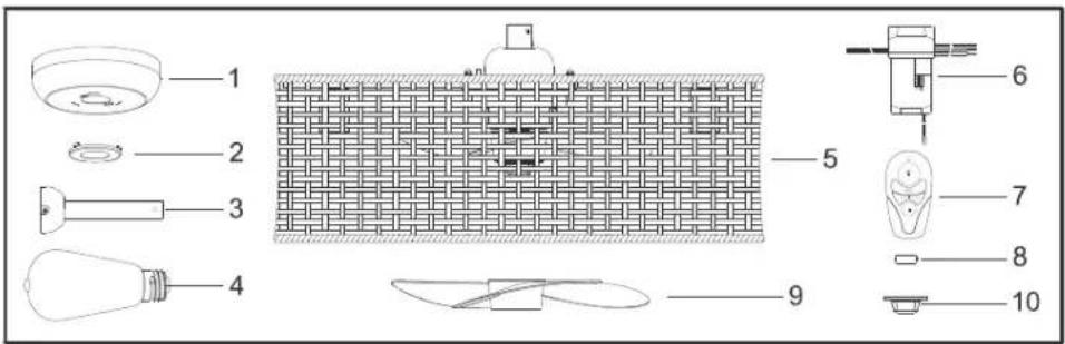
Exploded view diagram of a lighting fixture with numbered parts for identification
Unpack your fan and check the contents. You should have the following items:
-
Canopy assembly
-
Remote Control Transmitter
-
Cover
-
12V battery
-
Ball/downrod assembly
-
Fan blade
-
LED bulbs (4)
-
Finial
-
Fixture assembly
-
Receiver
-
Loose parts bag containing:
a. Mounting hardware Wire nuts (6)
Unpacking Your Fan 2.
Tools Required
Phillips screw driver, straight slot screw driver, adjustable wrench, step ladder, and wire cutters.
Mounting Options
If there isn't an existing eUL listed mounting box, then read the following instructions. Disconnect the power by removing fuses or turning off circuit breakers.
Secure the outlet box directly to the building structure. Use appropriate fasteners and building materials. The outlet box and its support must be able to fully support the moving weight of the fan (at least 35 lbs). Do not use plastic outlet boxes.
WARNING
TO REDUCE THE RISK OF FIRE, ELECTRIC SHOCK, OR OTHER PERSONAL INJURY, MOUNT FAN ONLY TO AN OUTLET BOX MARKED ACCEPTABLE FOR FAN SUPPORT AND USE THE MOUNTING SCREWS PROVIDED WITH THE OUTLET BOX. OUTLET BOXES COMMONLY USED FOR THE SUPPORT OF LIGHTING FIXTURES MAY NOT BE ACCEPTABLE FOR FAN SUPPORT AND MAY NEED TO BE REPLACED. CONSULT A QUALIFIED ELECTRICIAN IF IN DOUBT.
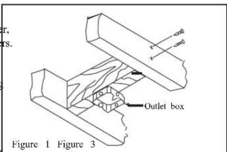
text_image
r, rs. y y y Outlet box Figure 1 Figure 3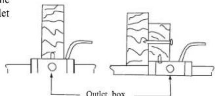
text_image
Outlet boxFigure 2
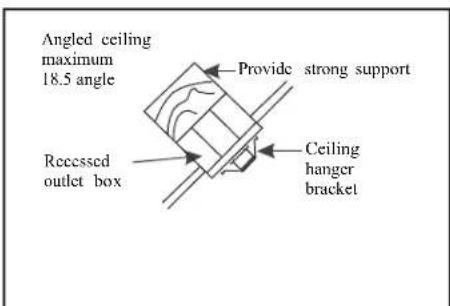
text_image
Angled ceiling maximum 18.5 angle Provide strong support Recessed outlet box Ceiling hanger bracketNote: You may need a longer downrod to maintain proper clearance when installing on a steep, sloped ceiling.
text_image
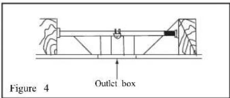
Figure 4 Outlet boxTo hang your fan where there is an existing fixture but no ceiling joist, you may need an installation hanger bar as shown in Figure 4
3. Installing Your Fan
Hanging theFan
REMEMBER to turn off the power. Follow the steps below to hang your fan properly:
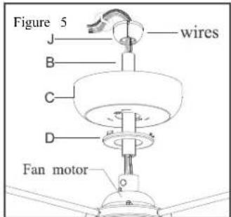
Step 1. Route the wires exiting the top of fan motor through the cover (D) and then through the canopy (C), downrod (B) and hanger ball (J) assembly.(Fig.5)
text_image
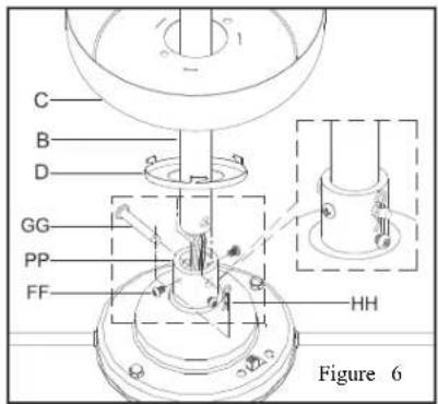
Figure 5 J wires B C D Fan motorStep 2. Insert the downrod (B) through the metal cover (D) and canopy (C). (Fig 6)
Step 3. Insert the end of downrod (B) through the connector (PP), align the two holes in the downrod (B) and the connector (PP). (Fig.6)
Step 4. Insert a plug pin (GG) through the holes in the downrod (B) and the connector (PP). (Fig.6)
Step 5. Insert the R-shaped pin (HH) though the hole near the end of the plug pin (GG) it snaps into its locked position. (Fig.6)
Step 6. Install the screw (FF) to the connect (PP), and make sure it's tighten, Screws (FF) should be tight against the downrod (B). (Fig.
text_image
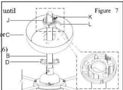
C B D GG PP FF HH Figure 6Step 7. Insert the hanger ball (J) onto the downrod (B), and then insert a plug pin (L) through the hole in the downrod (B). (Fig.7)
Step 8. Insert the plug pin to the slot cut of the hanger ball (J) until it snaps into its lock position. (Fig.6) two
Step 9. Use the Screw(K) to lock the hanger ball (J) to the downrod (B). (Fig.7)
text_image
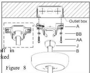
until J orC 6) B D Figure 7 K LStep 10. Install the Hanger bracket (A) on the outlet box by using the washer (BB) and screws(AA) provided with thelet box. (Fig.8)
Step 11. Put the hanger ball (J) through the open side of the ceiling mounting bracket (A), and then insert the hanger ball(J) to the slot cut off in the ceiling mounting bracket(A). (Fig.8)
text_image
Outlet box A BB AA J B If in ked Figure 8Make the Electric Connections
WARNING: To avoid possible electrical shock, be sure electricity is turned off at th main fuse box before wiring.
CODE SWITCH: Codes are set by pushing switches up or down. It is imperative that the code used for both transmitter and receiver exactly the same, otherwise remote controller will not work. Please note the code switch enable you to operate a second remote controller independently. For example, if you have two ceiling fans with 2 remote control units, set 2 different codes for each set of transmitter/receivers. This means you can operate each ceiling fan independently. Your remote control is ready for use after battery installation. (Fig.9)
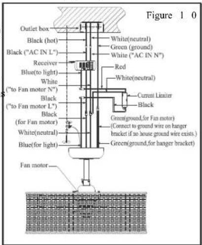
Step 1. Fan motor to Receiver Electrical and Current Limiter Connections: Connect the Black wire from the fan to Black wire mark "TO MOTOR L". Connect the White wire from the fan to the White wire marked "TO MOTOR N" from the receiver and the White wire from the Current limiter. Connect the blue (light) wire to the black wire from the Current Limiter. Connect the Red wire from the Current Limiter to the Blue wire from the Receiver. Secure wire connections with the plastic wire nuts provided. (Fig. 10)
will Step 2. Receiver to House Supply Wires Electrical Connections: Connect the black (hot) wire from the ceiling to the black wire marked "AC in L" from the receiver. Connect the white (neutral) wire from the ceiling to the white wire marked "AC in N" from the Receiver. Secure the wire connection with the plastic wire nuts provided. (Fig. 10)
Step 3. If your outlet box has a ground wire (green or bare copper) connect it to the fan ground wires; otherwise connect the hanging bracket ground wire to the mounting bracket. Secure the wire connection with plastic wire nuts provided. After connecting the wires spread them apart so that the green and white wires are on one side of the outlet box and black and blue wires are on the other side. Carefully tuck the wire connections up into the outlet box. (Fig. 10)
text_image
Figure 1.0 Outlet box Black (hot) Black ("AC IN L") Receiver Blue(to light) White ("to Fan motor N") Black ("to Fan motor L") Black (for Fan motor) White(neutral) Blue(for light) Fan motor White(neutral) Green (ground) White ("AC IN N") Red White(neutral) Current Limiter Black Green(ground,for Fan motor) (Cnect to ground wire on hanger bracket if no house ground wire exists.) Green(ground,for hanger bracket)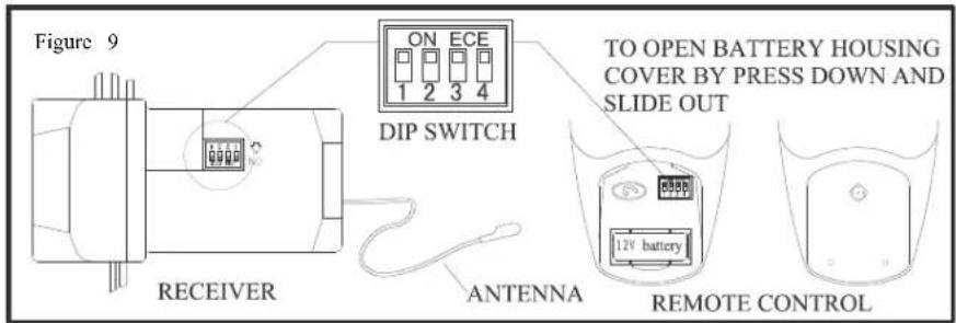
text_image
Figure 9 ON ECE 1 2 3 4 DIP SWITCH RECEIVER ANTENNA TO OPEN BATTERY HOUSING COVER BY PRESS DOWN AND SLIDE OUT 12V battery REMOTE CONTROLStep 4. Once the connection has been made, Installing the canopy:
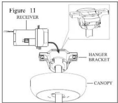
the receiver inserts into the down rod hangi bracket. The canopy comes up to cover the receiver and bracket. (Fig. 11)
text_image
Figure 11 RECEIVER HANGER BRACKET CANOPYAn additional safety support is provided to prevent the fan from falling. Secure the Support cable to the ceiling joist with screw and washer. Screw and Support cable holder lock the fixed Support cable. (Fig. 12)
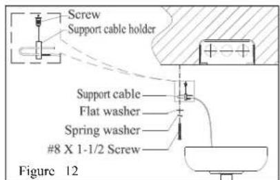
text_image
Screw Support cable holder Support cable Flat washer Spring washer #8 X 1-1/2 Screw Figure 12Step 1. Align the locking slots of the canopy (C) with the two screws (FF) in the mounting bracket (A). Push up to engage the slots and lock in place. (Fig. 13)
Step 2. Rotate the metal cover (D) clockwise to lock in the bottom of the canopy. (Fig. 1)
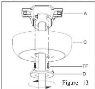
text_image
A C FF D Figure 13Installing the Fan blades, rattan shade and bulbs:
Step 1: Install the fan blades (M) onto the fan motor shaft (U). Put the R-shaped pin (R) into the motor shaft (U) to lock with a screwdriver or pliers. (Fig. 15) Left handed thread on the lock nut (Q). Install lock nut (Q) onto the motor shaft (U) after the fan blades (M) is installed. (Fig. 14)
Step 2. Screw light bulbs (F) into the fixture Sockets(S). (Fig. 14)

text_image
Figure 14 to E R U M F Q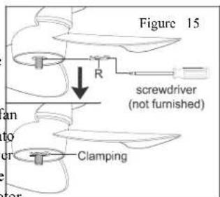
text_image
Figure 15 R screwdriver (not furnished) ClampingInstalling the battery
Install 12V A23 battery (included), To prevent damage to transmitter, remove the battery if not used long periods(Fig. 16)
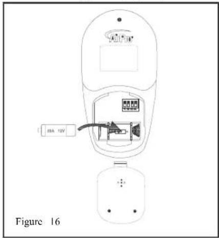
text_image
16 Figure 16Restore power to ceiling fan and testproficer operation.
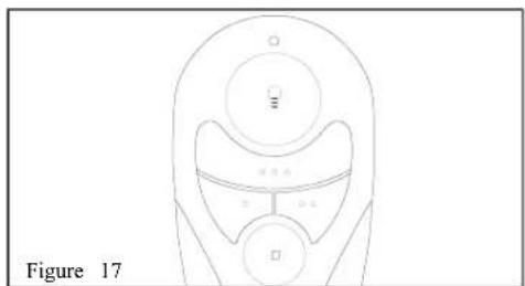
- Ⓞ,○○,○○○,"buttons:
These three buttons are used the fan speed as follow(Fig. 17):
○ = Low speed
○○ = Medium speed
○○○ = High speed
- " □ " button:
This button turns the offin
- The "≡ button turn the light ON or OFF and also controls the brightness setting. Press and release the button to turn the light ON or OFF. Press and hold the button to set tlesired brightness. The light keyamas auto-resume, it will stay at the same brightness as the last time was turned off.
natural_image
Line drawing of a mechanical device with three circular components and labeled parts (no text or symbols on the diagram itself)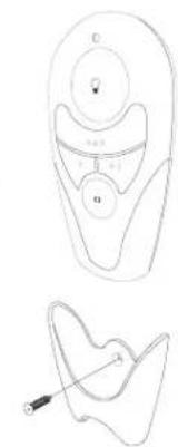
natural_image
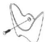
Line drawings of a device with labeled components (no text or symbols)Installation of Transmitter Wall Mount Holder with one screw.
7. OperatingYour Transmitter
The Reverse switch is located on the top of the motor housing. Slide the switch to the Left for warm weather operation. Slide the switch to the Right for cool weather operation. (Fig. 18)
NOTE: Wait for fan to stop before changing the setting of the slide switch.
Speed settings for warm or cool weather depend on factors such as the room size, ceiling height, number of fans, etc.
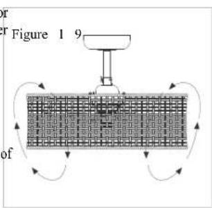
Warm weather - (Forward) A downward air flow creates a cooling effect as shown in Figure 19. This allows you to set your air conditioner on a higher setting without affecting your comfort.
Cool weather - (Reverse) An upward airflow moves warm air off the ceiling area as shown in Figure 20. This allows you to set your heating unit on a lower setting without affecting your comfort.
text_image
Figure 1 9 of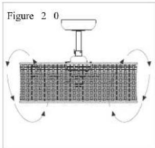
text_image
Figure 2 0
text_image
Figure 18 REVERSEHere are some suggestions to help you maintain 3 Cover small scratches with a light application of shoe polish. your fan
- Because of the fan's natural movement, some connections may become loose. Check
4.There is no need to oil your fan. The motor has permanently lubricated bearings.
the support connections, brackets, and blade 5. The fan comes with a pre-assembled blade and attachments twice a year. Make sure they are front guard for your easy installation. Check that secure. (It is not necessary to remove fan from all screws are tight and securely in place. ceiling.)
-
Use a lint free lightly damp cloth or duster to
-
Clean your fan periodically to help maintainemove dust from the blades.
its new appearance over the years. Use only a soft brush or lint-free cloth to avoid scratching the finish. The plating is sealed with a lacquer
to minimize discoloration or tarnishing. Do not use water when cleaning. This could damage the motor or possibly cause an electrical shock.
IMPORTANT MAKE SURE THE POWER IS OFF AT THE ELECTRICAL PANEL BOX BEFORE YOU ATTEMPT ANY REPAIRS. REFER TO THE SECTION "MAKING ELECTRICAL CONNECTIONS"
9. Care of four Fan
Problem Solution
Fan will not start. 1. Check circuit fuses or breakers.
-
Check line wire connections to the fan and switch wire connections in the switch housing. CAUTION: Make sure main poweroff.is
-
Check to make sure the dip switches from the transmitter and receiver are set to the same frequency.
-
Check the battery in the transmitter.
Fan sounds noisy. 1. Make sure all motor housing screws are snug.
-
Make sure wire nut connections are not rubbing against each other or the interior wall of the switch housing. CAUTION: Make sure main power off is
-
Allow a 24-hour "breaking-in" period. Most noise associated with a new fan disappear during this time.
-
Check that light bulb is also secure.
-
Some fan motors are sensitive to signals from solid-state variable speed controls. If you have installed this type of control, choose and install another type of control.
n....1.1
Remote control malfunction 1. Do not connect the fan with wall mounted variable speed control (s).
- Make sure the dip switches are set correctly.
Troubleshooting 10.
| Size | Speed Volts | Fan Power Consumption (without lights) WATT | Airflow CFM | Airflow Efficiency (Higher Is Better) CFM/WATT | Net Weight | Gross Weight | Cubic Feet | |
| 14in. | Low | 29.40 1 | 21.75 888.10 40.92 | 12.89 lb (5.85kg) | 18.74 lb (8.5kg) | 6.580cu. Ft. | ||
| Medium | 109.82 37.75 | |||||||
| High 37.10 133 | 1.40 35.88 | |||||||
These are approximate measures. They do not include Amps and Wattage used by the light kit.
© 2018 Progress Lighting, Inc.
701 Millennium Blvd.,
Greenville, SC 29607
All Rights Reserved
11. Specifications
natural_image
Line drawing of a woven basket with a top handle and central slot (no text or symbols)93138712_B
P250068
text_image
Exploded view diagram of a household appliance with numbered parts for identification
text_image
Figure 7 J K L C B Dtext_image
A C FF D Figure 13text_image
Figure 14 E R U M F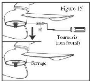
text_image
Figure 15 R Tournevis (non fourni) Serragenatural_image
Line drawing of a mechanical component with circular features and a central hub (no text or symbols)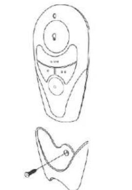
natural_image
Line drawings of a device with a circular head and a separate abstract shape (no text or symbols)text_image
Figure 19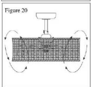
text_image
Figure 20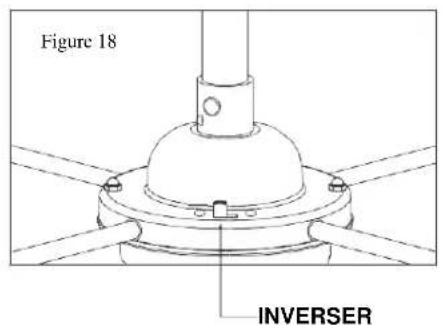
text_image
Figure 18 INVERSER© 2018 Progress Lighting, Inc.
701 Millennium Blvd.,
Greenville, SC 29607
natural_image
Line drawing of a woven basket-shaped lampshade with a top handle (no text or symbols)93138712_B P250068
text_image
Exploded view diagram of a wall-mounted device with numbered parts for identification
text_image
Figura 7 J K L C B Dtext_image
Figura 14 E R U M F Q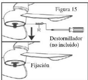
natural_image
Line drawing of a mechanical component with circular features and a central hub (no text or symbols)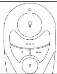
natural_image
Simple line drawing of a stylized robot head with circular components and a lightbulb on top (no text or symbols)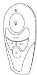
text_image
Figure 19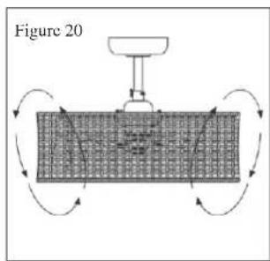
natural_image
Diagram of a robotic arm with rotating arrows indicating motion, no text or symbols present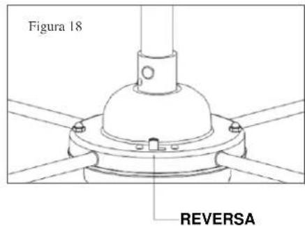
text_image
Figura 18 REVERSA© 2018 Progress Lighting, Inc.
701 Millennium Blvd.,
Greenville, SC 29607