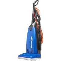
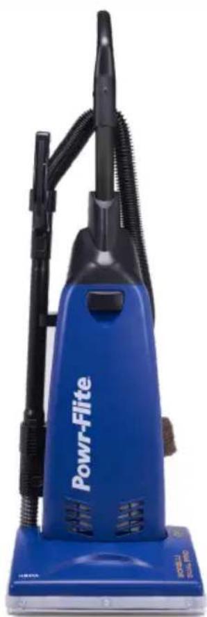
PV160-W14-U - Vacuum Cleaner Powr-Flite - Free user manual and instructions
Find the device manual for free PV160-W14-U Powr-Flite in PDF.


| Brand | Powr-Flite |
| Model | PV160-W14-U |
| Vacuum type | Upright vacuum |
| Power supply voltage | 115 V AC / 60 Hz |
| Suction motor power | 1,200 W / 10 A |
| Brush motor power | 222 W / 1.85 A |
| Bag capacity (dry) | 3.8 qt / 3.6 L |
| Airflow | 120 ft³/min / 3.4 m³/min |
| Water lift | 65 in / 1,650 mm |
| Filtration | HEPA 99.97% @ 0.3 micron |
| Brush width | 12 in / 305 mm |
| Number of extension cords | 2 cords of 30 ft / 9 m |
| Weight | 24.2 lb / 10.98 kg |
| Sound level | 69.9 dB (A) |
| Construction class | I |
| Protection rating | IP20 |
| Brush height adjustment | Automatic |
| Edge cleaning function | Yes (right side) |
| Onboard tools | Telescopic extension wand, stretch hose, dusting brush, crevice tool |
| Bag type | Disposable or reusable cloth bag (optional) |
| Pre-motor filter | Washable and reusable (ref. 90145) |
| Exhaust filter | Non-washable HEPA (ref. 90144) |
| Warranty | See website for details |
Frequently Asked Questions - PV160-W14-U Powr-Flite
User questions about PV160-W14-U Powr-Flite
0 question about this device. Answer the ones you know or ask your own.
Ask a new question about this device
Download the instructions for your Vacuum Cleaner in PDF format for free! Find your manual PV160-W14-U - Powr-Flite and take your electronic device back in hand. On this page are published all the documents necessary for the use of your device. PV160-W14-U by Powr-Flite.
USER MANUAL PV160-W14-U Powr-Flite
natural_image
Blue and black power-flame vacuum cleaner with attached hose (no visible text or symbols)Operating Instructions
PV160-W14-U
Getting Started
Introduction 4
Warranty 4
Grounding Instructions....5
Important Safety Instructions....6
Technical Specifications....8
Common Replacement Parts 8
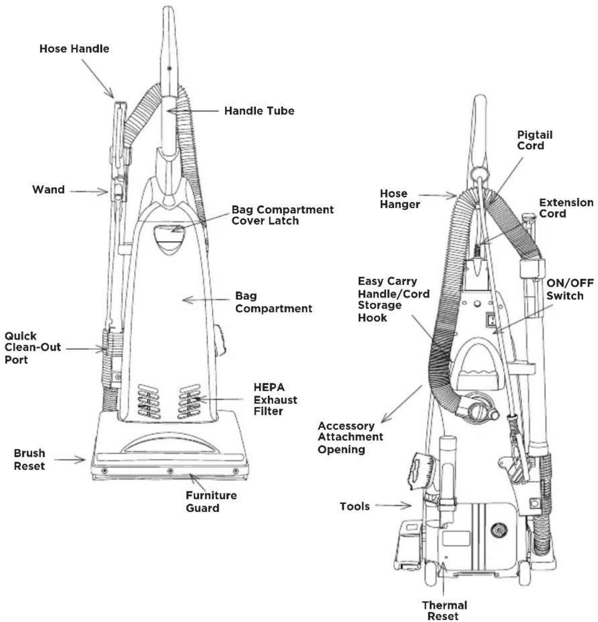
Parts Identification....9
Operation
Attach the Handle 10
Connect the Power Cord....10
On/Off Switch 10
Adjust the Handle ....11
Brush Head Adjustment ....11
Clean the Brush Head Hose 14
Circuit Breakers 15
For Best Performance ....15
Record of Purchase....16

natural_image
Simple line drawing of a shield with a checkmark (no text or symbols)Warranty
Please visit https://www.powr-flite.com/warranty-registration to learn more about your warranty and our warranty policy.

natural_image
Simple line icon of a hand pointing at an open book (no text or symbols)Warning Labels
Prior to operating the unit, read and understand completely this owner's manual paying special attention to warning labels. These labels indicate a potentially hazardous situation that could result in death or serious injury if not avoided. Use only as described in this manual.

Important
There are no owner serviceable parts inside this machine. Removal of screws and accessing internal components will void all warranty claims.
Your new Powr-Flite unit is a high quality, precision-made product. All parts used in the manufacturing of this unit have passed rigid quality control standards prior to assembly. Please safeguard the original receipt/invoice given at the time of purchase. If you experience any problems with your unit during the warranty period, the original receipt/invoice will act as proof of purchase.
Upon receipt, inspect outer box for exterior damage. Unpack all internal parts, ensure all items are present according to the owner's manual, and review components for damage.
Each unit is tested and thoroughly inspected prior to shipping. If damage is discovered, immediately notify the transportation company that delivered your machine and request an inspection. As a manufacturer, we are unable to act upon any claim for concealed damage and you must originate the claim. Be sure to keep the carton, packing inserts, and carrier's receipt until the inspector has verified your claim.
DANGER: Improper use of the grounding plug can result in a risk of electric shock.
WARNING!
Improper connection of the equipment-grounding conductor can result in a risk of electric shock. Check with a qualified electrician or service person if you are in doubt as to whether the outlet is properly grounded. DO NOT modify the plug provided with the appliance. If it will not fit the outlet, have a proper outlet installed by a qualified electrician.
Grounding Methods
This appliance must be grounded. If it should malfunction or breakdown, grounding provides a path of least resistance for electric current to reduce the risk electric shock. This machine is equipped with a cord having an equipment-grounding conductor and grounding plug. The plug must be inserted into an appropriate outlet that is properly installed and grounded in accordance with all local codes and ordinances.
This appliance is for use on a nominal 115-volt circuit, and has a grounding plug that looks like the plug illustrated in sketch A.
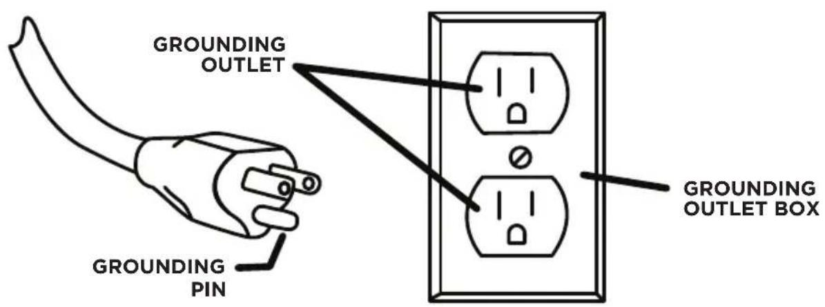
A
READ AND UNDERSTAND ALL INSTRUCTIONS BEFORE USING THIS UNIT
Read and understand this owner's manual and all labels on the unit before operating. Safety is a combination of common sense, staying alert, and knowing how your unit works. Use this unit only as described in this manual. Use only manufacturer's recommended attachments. To reduce the risk of personal injury or damage to your unit use only recommended accessories.
WARNING: To avoid fire, DO NOT use with a flammable or combustible liquid or floor cleaner.
WARNING: To avoid electric shock, DO NOT expose to rain. Store Indoors.
When using this unit, basic precautions should always be followed, including the following:
- DO NOT leave unit when plugged in. Unplug from outlet when not in use and before servicing.
- DO NOT allow unit to be used as a toy. Close attention is necessary when used around or near children.
- Use only as described in this manual. Use only manufacturer's recommended attachments.
- DO NOT use with damaged cord or plug. If unit is not working properly because it has been dropped, dropped into water, left outdoors, or damaged in any way, contact a service center
- DO NOT handle plug or appliance with wet hands.
• DO NOT put any objects into openings. - DO NOT use with any opening blocked: keep free of dust, lint, hair, or anything that may reduce air flow.
- Keep hair, loose clothing, fingers, and all parts of body away from openings and moving parts.
- DO NOT pick up anything that is smoking or burning such as cigarettes, matches, or hot ashes.
- DO NOT use to pick up hazardous chemicals.
- Turn off all controls before unplugging.
- DO NOT use to pick up flammable or combustible liquids such as gasoline or use in areas where they may be present.
- DO NOT use where oxygen or anesthetics are used.
- Replace damaged or worn parts immediately with genuine original equipment parts to maintain safety.
- This unit must be connected to a properly grounded outlet only. See grounding instructions.
- DO NOT use equipment out of doors or in the rain.
- DO NOT use equipment near or around flammable or explosive materials, fuels, or solvents.
- DO NOT allow the unit to freeze.
- Anyone designated to operate this equipment must, without fail, read and thoroughly understand all instructions and precautions prior to use.
- Do not operate equipment under any unsafe condition.

State of California Proposition 65 Warnings
WARNING: This product contains one or more chemicals known to the state of California to cause cancer.
WARNING: This product contains one or more chemicals known to the state of California to cause birth defects or other reproductive harm.

Intended Use
Do NOT modify this unit in any way or adapt it for any other use. Modification of this unit in any way will void all warranties and could create safety hazards.
natural_image
Line drawing of a vacuum cleaner with hoses and control panel (no text or symbols)
WARNING


SHOCK, FIRE AND EXPLOSION HAZARD. AVOID INJURY
- Do not operate with damaged power cord. Do not modify plug. Unplug power cord before machine service
• Do not use near flammable or toxic materials and burning debris - Do not use near flammable liquids, vapors or combustible dusts.
• Do not use outdoors or on wet surface. Do not expose to rain.

AVERTISSEMENT
RISQUE D'EXPLOSION, D'INCENDIE ET DE DECHARGE.
| Model | PV160-W14-U |
| Voltage/Frequency | 120VAC/60 Hz |
| Vacuum Motor Rating | 1200W/10A |
| Brush Motor Rating | 222W/1.85A |
| Bag Capacity -Dry | 3.8 Qt/3.6L |
| Airflow 120cfm/3.4 ccm | |
| Water Lift | 65 in./1650 mm |
| Filtration | 99.97@0.3 micron |
| Brush Width | 12 in./305 mm |
| Cable Length (2) 30'/9 M extension cords | |
| Weight 24.2 lbs./10.98 kg | |
| Noise Level 69.9 db (A) | |
| Construction Class | I |
| Protection | IP20 |
COMMON REPLACEMENT PARTS
| PV160-W14-U | |
| 90145 Pre-Motor Filter (Pkg of 1) | |
| 90144 HEPA Exhaust Filter | |
| 39334 Brush Assembly | |
| 39335 Brush Belt | |
| 39304 Rocker Switch | |
| X0161 30Ft. Extension Cord | |
| 39311 Wheel Assembly | |
| 39326 Vacuum Motor | |
| 39338 Brush Motor | |
| 90142 Crevice Tool | |
| 90143 Brush Tool | |
| X0162 Wand Assembly | |
Replacement Bags, Belts, and Filters
| Genuine Powr-Flite Vacuum Bags (25 per package) X1999 | |
| Genuine Powr-Flite Vacuum Belt (1 per package) 39335 | |
| Pre-Motor Filter (1 per package) 90145 | |
| HEPA Exhaust Filter (1 per package) 90144 | |
| Reusable Cloth Bag w/Clamp CM-CLOTH |
How to Attach the Handle to the Vacuum Cleaner
The vacuum cleaner and the handle are packed separately.
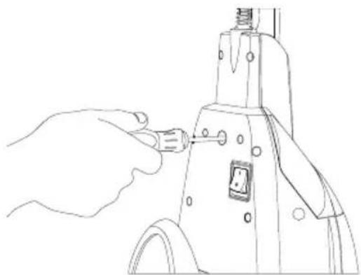
- After first removing the handle screw, insert handle into the hole on top of the vacuum cleaner. (Fig. 1)
- Line up the small hole on the handle with the small hole on the vacuum cleaner and insert the screw. Make sure the screw is secured tightly.
natural_image
Line drawing of a hand using a tool to adjust or install a mechanical component (no text or symbols present)Fig. 1
Connect the Power Cord
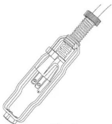
Attach up to (2) 30', 16/3 SJT extension cords (provided) to the pigtail on the vacuum. Ensure all cord connections are made using the cord lock system(s) (Fig. 2) that come with the vacuum.
natural_image
Technical line drawing of a mechanical component with threaded end and internal structure (no text or symbols)Fig. 2
ON/OFF Switch
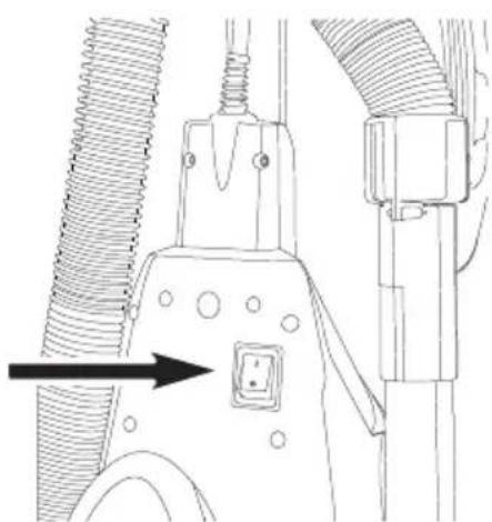
- To turn the vacuum on, push the switch located the rear of the unit to the (1) position. (Fig. 3)
- To turn the vacuum off, push the switch to the (O) position.
natural_image
Technical line drawing of a mechanical device with threaded components and a highlighted square component (no text or symbols)Fig. 3
NOTE: The brush motor is only activated when the handle is moved back to the working position.
The handle on this vacuum cleaner can be set to one of three positions - upright, working or low.
How to Adjust the Handle
- To release the handle, step on the left rear corner of the vacuum cleaner (Fig. 1).
- Upright position - for when cleaning tools are being used or for storage (Fig. 2). Handle locks in this position.
- Working position - for normal cleaning (Fig. 3).
- Low position - for cleaning under furniture (Fig. 4).

natural_image
Line drawings of four different types of cleaning or cleaning equipment, showing foot, chair, and vehicle components (no text or symbols)Brush Head Adjustment
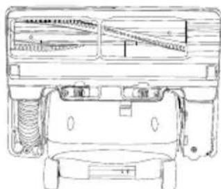
Your Powr-Flite upright vacuum cleaner is designed with a Self-Adjusting Brush Head. No manual adjustments are required. The height of the brush head is instantly adjusted to carpet pile height. This self-adjusting feature allows the brush head to float evenly over all carpet pile surfaces.
natural_image
Technical line drawing of a mechanical assembly with no visible text or symbolsFig. 5
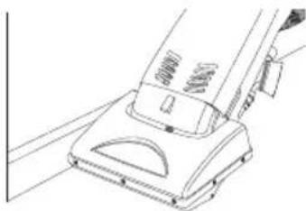
The edge cleaning feature provides improved cleaning near walls and stationary furniture. For maximum edge cleaning, position the right side of the vacuum from the user's perspective near walls or stationary furniture.
natural_image
Line drawing of a vacuum cleaner with attached blade and handle (no text or symbols)Fig. 6
Cleaning with On-Board Tools
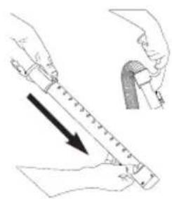
This vacuum is equipped with on-board cleaning tools including a metal telescopic wand, stretch hose, dusting brush and crevice tool.
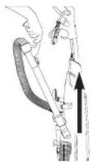
- To use the cleaning tools, lift the hose handle straight up from the vacuum (Fig. 1).
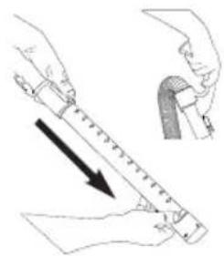
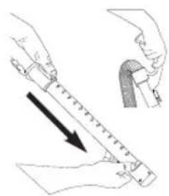
- Extend the wand by pushing the button forward and pulling the smaller wand out of the larger wand (Fig.2).
- Attach any of the on-board tools to the end of the wand or if you do not need the wand, any tool can be connected directly onto the hose handle.
natural_image
Illustration of a person using a cable to lift a weight, with an upward arrow indicating motion (no text or symbols)Fig. 1
natural_image
Illustration of hands using a ruler to measure a quantity, with an arrow indicating measurement direction (no text or symbols present)Fig. 2
MAINTENANCE
Always operate the vacuum cleaner with a vacuum bag installed.
How to Change the Vacuum Bag
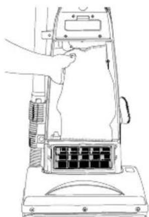
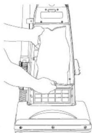
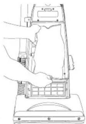
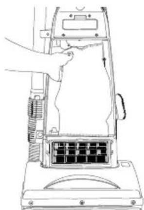
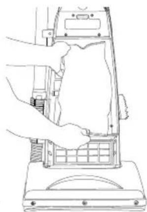
- Unplug the vacuum cleaner. Remove the bag compartment cover and remove the used bag from the bag holder (Fig. 3).
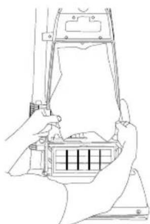
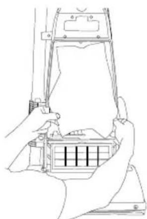
- Attach the new vacuum bag onto the bag holder (Fig. 4).
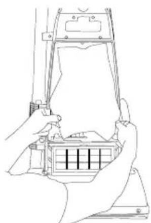
- Pull the bottom corners of the new vacuum bag (Fig. 5).
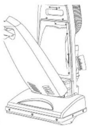
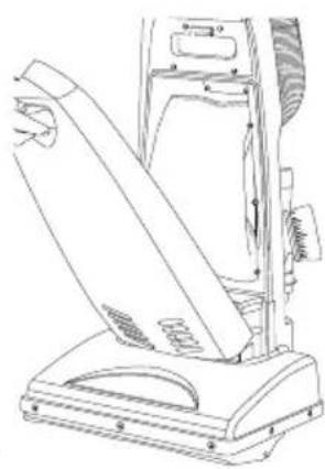
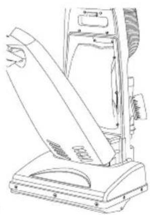
- Reinsert the tab on the end of the bag compartment cover into the groove on the bag compartment housing. Press it into place and fasten the bag compartment tightly (Fig. 6).
natural_image
Line drawing of a hand operating a vacuum cleaner with a grid vent (no text or symbols)Fig. 3
natural_image
Line drawing of a hand inserting a component into a device (no text or symbols)Fig. 4
natural_image
Line drawing of hands operating a mechanical device with a grid-patterned base (no text or symbols)Fig. 5
natural_image
Line drawing of a vacuum cleaner with attached clamped components (no text or symbols)Fig. 6
How to Change Filters
Your Powr-Flite vacuum cleaner is equipped with an Pre-Motor Filter and a HEPA Exhaust filter.
These filters capture fine dust particles and protect the motor from dirt. It is important to replace the HEPA Exhaust filter approximately every six months.
To Change or Clean the Pre-Motor Filter
- Unplug the vacuum cleaner. Remove the bag compartment cover and the bag.
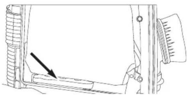
- Remove the Pre-Motor Filter (Fig.1) and shake or brush off the dirt then replace filter.
- Replace the bag and bag compartment cover.
To Change the HEPA Exhaust Filter
- Unplug the vacuum cleaner. Remove the bag compartment cover.
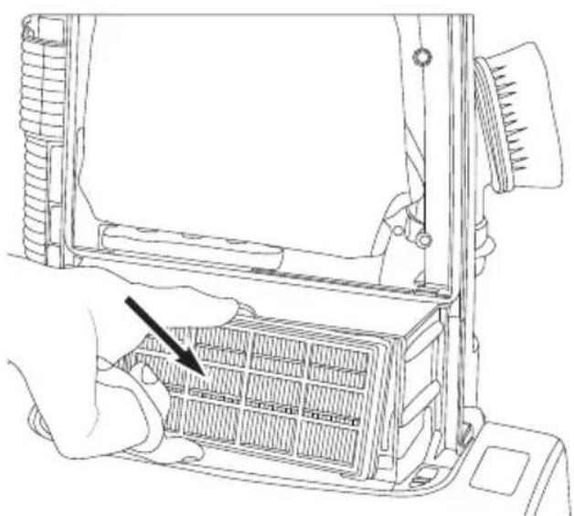
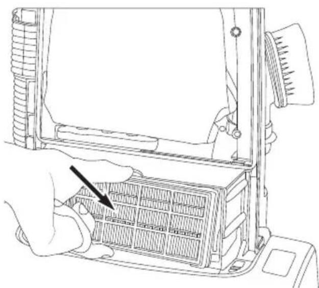
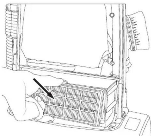
- Remove the HEPA Exhaust filter from the front of the bag compartment. (Fig. 2)
- Insert a new filter and replace the bag compartment cover.
Note: HEPA Exhaust filters cannot be washed and used again.
natural_image
Technical line drawing of a mechanical assembly with a directional arrow indicating movement (no text or symbols)Fig. 1
natural_image
Line drawing of a hand inserting a grid into a device component (no text or symbols)Fig. 2

CAUTION: Unplug the vacuum cleaner before performing any of these steps.
How to Remove the Bottom Plate
- Place the vacuum cleaner in the low position (see page 9). Turn the vacuum over.
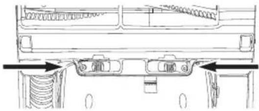
- Slide the clips toward each other (Fig. 1).
- Remove the bottom plate.
natural_image
Technical line drawing of a mechanical assembly with springs and connectors (no text or symbols)Fig. 1
How to Replace the Belt
- Turn the unit over and remove the bottom plate as described in the above section.
- Remove the agitator by pulling it straight out.
- Remove the belt from the agitator and motor pulley.
- Loop a new belt over the motor pulley and over the end of the agitator.
- Stretch the belt over the agitator while inserting it back into the brush head housing.
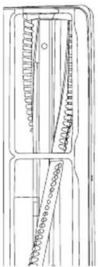
- Replace the bottom plate by hooking the front end of the plate into the two ribs on the front end of the brush head housing. (Fig. 2) Press the bottom plate into place by sliding the clips away from each other.
natural_image
Pure technical line drawing of a mechanical component without any text, numbers, or symbolsFig. 2
NOTE: To ensure maximum cleaning efficiency, check the belt regularly to ensure it is in good condition. Replace the belt if it is stretched, cracked or if excessive slipping is occurring.
How to Clean the Brush Head Hose
- Remove the wand from the wand / hose holder as shown on page 10.
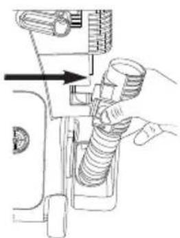
- Squeeze the tabs on both sides of the quick clean-out port and pull away from the vacuum (Fig. 1).
- Check above and below the port opening for obstructions.
- Remove any obstructions.
- Replace the quick clean-out port by squeezing both tabs and pushing it back into the wand / hose holder.
natural_image
Technical line drawing of a mechanical assembly with a hand operating a cylindrical component (no text or symbols)Fig. 1

CAUTION: Unplug the vacuum cleaner before performing any of these steps.
Your new vacuum cleaner is circuit breaker protected to prevent motor damage due to airflow or brush obstruction. Should your vacuum cleaner experience an obstruction, the circuit breaker will trip and safely turn off the motor.
To reset circuit breaker:
-
Press the on/off switch to the off position "O" and unplug the vacuum cleaner cord.
-
Check brush and remove any entangled objects. Remove bottom plate to access obstruction if necessary (see page 12).
-
Check for airflow obstruction and remove obstruction (full bag, clog in brush head hose, clog in wand/hose, clogged filters, etc.)
-
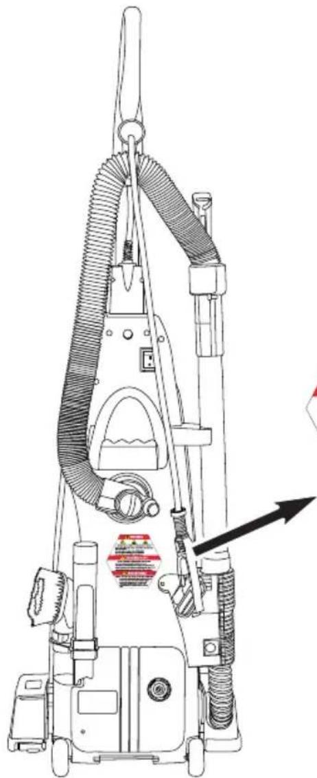
After removing obstruction reset the circuit breaker by pushing the reset button and resume operation (Fig. 1).
NOTICE: Do not repeatedly reset circuit breaker button without removing obstruction, motor failure may result and void warranty. If vacuum cleaner fails to turn on, contact an Authorized Service Center.

natural_image
Technical line drawing of a vehicle front view with a black arrow pointing to a component detail (no text or symbols)Thermal Reset
For Best Performance
Keep machine and all accessories clean and in good operating condition.
Change vacuum bags and filters as recommend to maintain optimum cleaning efficiency.
Always use genuine bags, filters and parts, as use of other products may result in poor cleaning or filtration performance. Powr-Flite filtration products are designed for maximum performance.
Have machine checked periodically by the retailer where you purchased your Powr-Flite vacuum.
Store machine carefully in dry area.
For optimum cleaning performance and safety, follow your owner's manual.
Powr-Flite
Powr-Flite
3101 Wichita Court
Ft. Worth, TX 76140-1755
Phone: 817-551-0700
WWW.POWR-FLITE.COM

Record of Purchase
Serial Number:
Purchase Date: ____
Dealer:
Phone Number:
Powr-Flite®
Borelli Dual Pro™
natural_image
Blue and black power-flite vacuum cleaner with attached hose (no visible text or symbols)natural_image
Simple line drawing of a shield with a checkmark (no text or symbols)Garantía
Visite https://www.powr-flite.com/warranty-registration
natural_image
Simple line icon of a hand pointing at an open book (no text or symbols)Importante
Uso previsto
natural_image
Line drawing of a vacuum cleaner with hoses and control panel (no text or symbols)
WARNING


SHOCK, FIRE AND EXPLOSION HAZARD. AVOID INJURY
- Do not operate with damaged power cord. Do not modify plug. Unplug power cord before machine service
- Do not use near flammable or toxic materials and burning debris
- Do not use near flammable liquids, vapors or combustible dusts.
• Do not use outdoors or on wet surface. Do not expose to rain.

AVERTISSEMENT
RISQUE D'EXPLOSION, D'INCENDIE ET DE DECHARGE.
natural_image
Line drawing of a hand using a tool to adjust or install a mechanical component (no text or symbols present)Fig. 1
natural_image
Technical line drawing of a mechanical component with threaded end and internal structure (no text or symbols)Fig. 2
natural_image
Technical line drawing of a mechanical component with threaded spring and mounting bracket (no text or symbols)Fig. 3
natural_image
Technical line drawings of four different types of cleaning or assembly components (no text or symbols)natural_image
Technical line drawing of a mechanical device with internal components (no text or symbols)Fig. 5
natural_image
Line drawing of a vacuum cleaner with attached blade and handle (no text or symbols)Fig. 6
natural_image
Illustration of a hand holding a rope with a belt and upward arrow (no text or symbols)Fig. 1
natural_image
Illustration of hands using a ruler to measure a quantity, with an arrow indicating measurement direction (no text or symbols present)Fig. 2
MANTENIMIENTO
natural_image
Line drawing of a hand operating a portable air conditioner unit with a grid vent (no text or symbols)Fig. 3
natural_image
Line drawing of a hand inserting a plastic into a device component (no text or symbols)Fig. 4
natural_image
Line drawing of hands operating a mechanical device with a grid-patterned base (no text or symbols)Fig. 5
natural_image
Line drawing of a mechanical device with no visible text or symbolsFig. 6
natural_image
Technical line drawing of a mechanical assembly with a directional arrow indicating movement (no text or symbols)Fig. 1
natural_image
Line drawing of a hand inserting a grid into a device component (no text or symbols)Fig. 2

natural_image
Technical line drawing of a mechanical assembly with springs and connectors (no text or symbols)Fig. 1
natural_image
Pure technical line drawing of a mechanical component without any text, numbers, or symbolsFig. 2
natural_image
Mechanical assembly diagram showing a hand operating a threaded component with a directional arrow (no text or labels)Fig. 1

natural_image
Technical line drawing of a vehicle front view showing a vehicle body, wheels, and a directional arrow (no text or symbols)Reinicio térmico
natural_image
Blue and black power-flite vacuum cleaner with attached hose (no visible text or symbols)natural_image
Simple line drawing of a shield with a checkmark (no text or symbols)Garantie
natural_image
Simple line icon of a hand pointing at an open book (no text or symbols)Important
Utilisation prévue
natural_image
Line drawing of a vacuum cleaner with hoses and control panel (no text or symbols)
WARNING


SHOCK, FIRE AND EXPLOSION HAZARD. AVOID INJURY
- Do not operate with damaged power cord. Do not modify plug. Unplug power cord before machine service
• Do not use near flammable or toxic materials and burning debris
- Do not use near flammable liquids, vapors or combustible dusts.
• Do not use outdoors or on wet surface. Do not expose to rain.

AVERTISSEMENT
RISQUE D'EXPLOSION, D'INCENDIE ET DE DECHARGE.
natural_image
Line drawing of a hand using a tool to adjust or install a mechanical component (no text or symbols present)Fig. 1
natural_image
Technical line drawing of a mechanical component with threaded end and internal structure (no text or symbols)Fig. 2
natural_image
Technical line drawing of a mechanical component with threaded ends and a highlighted section (no text or symbols)Fig. 3
natural_image
Line drawings of four different types of indoor air purifier or scrubber device components (no text or symbols)natural_image
Technical line drawing of a mechanical assembly with no visible text or symbolsFig. 5
natural_image
Line drawing of a vacuum cleaner with attached blade and handle (no text or symbols)Fig. 6
natural_image
Illustration of a person using a cable to lift a weight, with an upward arrow indicating motion (no text or symbols)Fig. 1
natural_image
Illustration of hands using a ruler to measure a quantity, with an arrow indicating measurement direction (no text or symbols present)Fig. 2
natural_image
Line drawing of a hand operating a vacuum cleaner with a grid vent (no text or symbols)Fig. 3
natural_image
Line drawing of a hand inserting a component into a device (no text or symbols)Fig. 4
natural_image
Line drawing of hands operating a mechanical device with a grid-patterned base (no text or symbols)Fig. 5
natural_image
Line drawing of a vacuum cleaner with attached clamped components (no text or symbols)Fig. 6
natural_image
Technical line drawing of a mechanical assembly with a directional arrow indicating movement (no text or symbols)Fig. 1
natural_image
Line drawing of a hand inserting a grid into a device component (no text or symbols)Fig. 2

natural_image
Technical line drawing of a mechanical assembly with springs and connectors (no text or symbols)Fig. 1
natural_image
Pure technical line drawing of a mechanical component without any text, numbers, or symbolsFig. 2
natural_image
Mechanical assembly diagram showing a hand operating a cylindrical component with a spring-like shaft (no text or symbols visible)Fig. 1

natural_image
Pure mechanical diagram showing a vehicle interior with no text, numbers, or symbols- Getting Started
- Operation
- Warranty
- Warning Labels
- Important
- WARNING!
- Grounding Methods
- READ AND UNDERSTAND ALL INSTRUCTIONS BEFORE USING THIS UNIT
- When using this unit, basic precautions should always be followed, including the following:
- State of California Proposition 65 Warnings
- Intended Use
- WARNING
- SHOCK, FIRE AND EXPLOSION HAZARD. AVOID INJURY
- AVERTISSEMENT
- RISQUE D'EXPLOSION, D'INCENDIE ET DE DECHARGE.
- COMMON REPLACEMENT PARTS
- How to Attach the Handle to the Vacuum Cleaner
- Connect the Power Cord
- ON/OFF Switch
- How to Adjust the Handle
- Brush Head Adjustment
- Cleaning with On-Board Tools
- MAINTENANCE
- How to Change the Vacuum Bag
- How to Change Filters
- To Change or Clean the Pre-Motor Filter
- To Change the HEPA Exhaust Filter
- How to Remove the Bottom Plate
- How to Replace the Belt
- How to Clean the Brush Head Hose
- To reset circuit breaker:
- For Best Performance
- Powr-Flite
- Record of Purchase
- Powr-Flite®
- Borelli Dual Pro™
- Garantía
- Importante
- Uso previsto
- MANTENIMIENTO
- Garantie
- Utilisation prévue
Brand : Powr-Flite
Model : PV160-W14-U
Category : Vacuum Cleaner