
M18 2970-20 - Industrial inspection tool MILWAUKEE - Free user manual and instructions
Find the device manual for free M18 2970-20 MILWAUKEE in PDF.

| Product Type | Pipe Inspection System (Industrial Inspection Tool) |
| Brand / Model | Milwaukee / M18 2970-20 (500 GB Command Center) |
| Power Source | M18™ Battery Pack (18 V DC) |
| Internal Storage Capacity | 500 GB (Internal Hard Drive) |
| Display | LCD Screen (M18™ Wireless Monitor) |
| Wireless Connectivity | WiFi (Range up to 200 ft / 60.9 m) |
| Maximum Video Resolution | 1080p at 30 fps |
| Image Resolution | Up to 1920 × 1080 pixels |
| Digital Zoom | 8x with Pan Feature |
| Locating Functions | Sonde (33 kHz, 512 Hz, 640 Hz) and Cable Tracking (33 kHz, 83 kHz) |
| Camera Heads | Self-leveling Ø 25 mm and 34 mm, Sapphire Glass Lens, Polycarbonate LED Guard |
| Available Reels | 30.5 m (100′) Flexible, 36.5 m (120′) and 60.9 m (200′) Semi-Rigid, 60.9 m (200′) and 99 m (325′) Rigid |
| Mounting / Transport | Swivel Mount on Reel, Backpack Plate for 120′ and 100′ Reels, Shoulder Strap for 100′ |
| Operating Temperature | 0 °F to 125 °F (approx. -18 °C to 52 °C) |
| ONE-KEY™ Technology | Setup, Lockout, and Tracking via Mobile App (iOS / Android) |
| Maintenance | Clean with damp cloth and mild soap; do not immerse; inspect push cable for wear |
| Safety | Wear PPE (gloves, goggles, mask); avoid explosive atmospheres; read full manual |
| Warranty | 5-Year Limited Warranty (US and Canada) for power tool; exceptions apply |
Frequently Asked Questions - M18 2970-20 MILWAUKEE
User questions about M18 2970-20 MILWAUKEE
0 question about this device. Answer the ones you know or ask your own.
Ask a new question about this device
Download the instructions for your Industrial inspection tool in PDF format for free! Find your manual M18 2970-20 - MILWAUKEE and take your electronic device back in hand. On this page are published all the documents necessary for the use of your device. M18 2970-20 by MILWAUKEE.
USER MANUAL M18 2970-20 MILWAUKEE
2970-20: M18™ 500GB Control Hub
2971-20: M18 ^TM Wireless Monitor
3972-20: 100' Flexible Pipeline Inspection Reel
3973-20: 120' Mid-Stiff Pipeline Inspection Reel
3974-20: 200' Stiff Pipeline Inspection Reel
3975-20: 200' Mid-Stiff Pipeline Inspection Reel
3976-20: 325' Stiff Pipeline Inspection Reel
48-53-2970: Tablet Mount
WARNING To reduce the risk of injury, the user must read and understand this manual.
3972-20: 100' Flexible Pipeline Inspection Reel
3973-20: 120' Mid-Stiff Pipeline Inspection Reel
3974-20: 200' Stiff Pipeline Inspection Reel
3975-20: 200' Mid-Stiff Pipeline Inspection Reel
3976-20: 325' Stiff Pipeline Inspection Reel
48-53-2970: Tablet Mount
GENERAL POWER TOOL SAFETY WARNINGS
⚠ WARNING
Read all safety warnings, instructions, illustrations and specifications for this power tool. Failure to follow all instructions listed below may result in fire and/or serious injury. Save all warnings and instructions for future the term "power tool" in the warnings refers to your mains-operated (corded) battery-operated (cordless) power tool.
WORK SAFETY AREA
- Keep work area clean and well lit. Cluttered or dark areas invite accidents.
- Do not operate power tools in explosive atmospheres, such as in the presence of flammable liquids, gases or dust. Power tools create sparks which may ignite the dust or fumes.
- Keep children and bystanders away while operating a power tool. Distractions can cause you to lose control.
ELECTRICAL SAFETY
- Power tool plugs must match the outlet. Never modify the plug in any way. Do not use any adapter plugs with earthed (grounded) power tools. Unmodified plugs and matching outlets will reduce risk of electric shock.
- Avoid body contact with earthed or grounded surfaces, such as pipes, radiators, ranges and refrigerators. There is an increased risk of electric shock if your body is earthed or grounded.
- Do not expose power tools to rain or wet conditions. Water entering a power tool will increase the risk of electric shock.
- Do not abuse the cord. Never use the cord for carrying, pulling or unplugging the power tool. Keep cord away from heat, oil, sharp edges or moving parts. Damaged or entangled cords increase the risk of electric shock.
- When operating a power tool outdoors, use an extension cord suitable for outdoor use. Use of a cord suitable for outdoor use reduces the risk of electric shock.
- If operating a power tool in a damp location is unavoidable, use a ground fault circuit interrupter (GFCI) protected supply. Use of an GFCI reduces the risk of electric shock.
PERSONAL SAFETY
- Stay alert, watch what you are doing and use common sense when operating a power tool. Do not use a power tool while you are tired or under the influence of drugs, alcohol or medication. A moment of inattention while operating power tools may result in serious personal injury.
- Use personal protective equipment. Always wear eye protection. Protective equipment such as a dust mask, non-skid safety shoes, hard hat or hearing protection used for appropriate conditions will reduce personal injuries.
- Prevent unintentional starting. Ensure the switch is in the off position before connecting to power source and/or battery pack, picking up or carrying the tool. Carrying power tools with your finger on the switch or energizing power tools that have the switch on invites accidents.
- Remove any adjusting key or wrench before turning the power tool on. A wrench or a key left attached to a rotating part of the power tool may result in personal injury.
-
Do not overreach. Keep proper footing and balance at all times. This enables better control of the power tool in unexpected situations.
-
Dress properly. Do not wear loose clothing or jewelry. Keep your hair and clothing away from moving parts. Loose clothes, jewelry or long hair can be caught in moving parts.
- If devices are provided for the connection of dust extraction and collection facilities, ensure these are connected and properly used. Use of dust collection can reduce dust-related hazards.
- Do not let familiarity gained from frequent use of tools allow you to become complacent and ignore tool safety principles. A careless action can cause severe injury within a fraction of a second.
POWER TOOL USE AND CARE
- Do not force the power tool. Use the correct power tool for your application. The correct power tool will do the job better and safer at the rate for which it was designed.
- Do not use the power tool if the switch does not turn it on and off. Any power tool that cannot be controlled with the switch is dangerous and must be repaired.
- Disconnect the plug from the power source and/or remove the battery pack, if detachable, from the power tool before making any adjustments, changing accessories, or storing power tools. Such preventive safety measures reduce the risk of starting the power tool accidentally.
- Store idle power tools out of the reach of children and do not allow persons unfamiliar with the power tool or these instructions to operate the power tool. Power tools are dangerous in the hands of untrained users.
- Maintain power tools and accessories. Check for misalignment or binding of moving parts, breakage of parts and any other condition that may affect the power tool's operation. If damaged, have the power tool repaired before use. Many accidents are caused by poorly maintained power tools.
- Keep cutting tools sharp and clean. Properly maintained cutting tools with sharp cutting edges are less likely to bind and are easier to control.
- Use the power tool, accessories and tool bits etc. in accordance with these instructions, taking into account the working conditions and the work to be performed. Use of the power tool for operations different from those intended could result in a hazardous situation.
- Keep handles and grasping surfaces dry, clean and free from oil and grease. Slippery handles and grasping surfaces do not allow for safe handling and control of the tool in unexpected situations.
BATTERY TOOL USE AND CARE
- Recharge only with the charger specified by the manufacturer. A charger that is suitable for one type of battery pack may create a risk of fire when used with another battery pack.
- Use power tools only with specifically designated battery packs. Use of any other battery packs may create a risk of injury and fire.
- When battery pack is not in use, keep it away from other metal objects, like paper clips, coins, keys, nails, screws or other small metal objects, that can make a connection from one terminal to another. Shorting the battery terminals together may cause burns or a fire.
-
Under abusive conditions, liquid may be ejected from the battery; avoid contact. If contact accidentally occurs, flush with water. If liquid contacts eyes, additionally seek medical help. Liquid ejected from the battery may cause irritation or burns.
-
Do not use a battery pack or tool that is damaged or modified. Damaged or modified batteries may exhibit unpredictable behavior resulting in fire, explosion or risk of injury.
- Do not expose a battery pack or tool to fire or excessive temperature. Exposure to fire or temperature above 265°F (130°C) may cause explosion.
- Follow all charging instructions and do not charge the battery pack or tool outside the temperature range specified in the instructions. Charging improperly or at temperatures outside the specified range may damage the battery and increase the risk of fire.
SERVICE
- Have your power tool serviced by a qualified repair person using only identical replacement parts. This will ensure that the safety of the power tool is maintained.
- Never service damaged battery packs. Service of battery packs should only be performed by the manufacturer or authorized service providers.
SPECIFIC SAFETY RULES FOR PIPELINE INSPECTION SYSTEMS
- Use latex or rubber gloves, goggles, face shields, protective clothing, and respirator when chemicals, bacteria or other toxic or infectious substances are suspected to be in a drain line. Drains may contain chemicals, bacteria and other substances that may cause burns, be toxic or infectious or may result in other serious personal injury.
- Practice good hygiene. Do not eat or smoke while handling or operating the tool. After handling or operating equipment, use hot, soapy water to wash hands and other body parts exposed to drain contents. This will help reduce the risk of health hazards due to exposure to toxic or infectious material.
- Always check the work area before beginning a job. Do not allow cable to contact electrical, chemical, or moving hazards.
- Do not use the cable to clear clogs or move obstructions. This is not a drain cleaner!
- Inspect cable for wear and damage before use. Do not twist, kink or over bend cables. Replace a worn or damaged cable before use.
- To reduce the risk of fire, personal injury, and product damage due to a short circuit, never immerse your tool, battery pack or charger in fluid or allow a fluid to flow inside them. Corrosive or conductive fluids, such as seawater, certain industrial chemicals, and bleach or bleach containing products, etc., can cause a short circuit.
- Recharge battery packs only with the charger specified for the battery. For specific charging instructions, read the operator's manual supplied with your charger and battery.
- CAUTION Use care when transporting this tool when the reel and backpack are connected. Tipping may occur.
- Always use common sense and be cautious when using tools. It is not possible to anticipate every situation that could result in a dangerous outcome. Do not use this tool if you do not understand these operating instructions or you feel the work is beyond your capability; contact Milwaukee Tool or a trained professional for additional information or training.
- Maintain labels and nameplates. These carry important information. If unreadable or missing, contact a MILWAUKEE service facility for a free replacement.
- ⚠️WARNING Some dust created by power sanding, sawing, grinding, drilling, and other construction activities contains chemicals known to cause cancer, birth defects or other reproductive harm. Some examples of these chemicals are:
- lead from lead-based paint
• crystalline silica from bricks and cement and other masonry products, and
• arsenic and chromium from chemically treated lumber.
Your risk from these exposures varies, depending on how often you do this type of work. To reduce your exposure to these chemicals: work in a well-ventilated area, and work with approved safety equipment, such as those dust masks that are specially designed to filter out microscopic particles.
FEDERAL COMMUNICATIONS COMMISSION
⚠ WARNING This is a class A product. In a domestic environment this product may cause radio interference in which case the user may be required to take adequate measures.
This equipment has been tested and found to comply with the limits for a Class A digital device, pursuant to Part 15 of the FCC Rules. These limits are designed to provide reasonable protection against harmful interference when the equipment is operated in a commercial environment. This equipment generates, uses, and can radiate radio frequency energy and, if not installed and used in accordance with the instruction manual, may cause harmful interference to radio communications. Operation of this equipment in a residential area is likely to cause harmful interference in which case the user will be required to correct the interference at his own expense.
This device complies with Part 15 of the FCC Rules.
Operation is subject to the following two conditions:
(1) this device may not cause harmful interference, and
(2) this device must accept any interference received, including interference that may cause undesired operation.
SYMBOLOGY

Volts

Direct Current
Federal Communications Commission

Do not allow battery to contact corrosive or conductive fluid

To prevent electric shock, do not allow product to contact live electrical parts

Chemical Burn Hazard - Keep away from children
SPECIFICATIONS
Volts 18 DC
Battery Type...... M18™
Charger Type...... M18™
Recommended Ambient
Operating Temperature.... 0°F to 125°F
M18 ^TM BATTERIES
⚠WARNING Recharge only with the charger specified for the battery. For specific charging instructions, read the operator's manual supplied with your charger and battery. Removing/Inserting the Battery.
To remove the battery, push in the release buttons and pull the battery pack away from the tool.
⚠ WARNING Always remove battery pack before changing or removing accessories.
To insert the battery, slide the pack into the body of the tool. Make sure it latches securely into place.
⚠ WARNING Only use accessories specifically recommended for this tool. Others may be hazardous.
ONE-KEY™
To learn more about the ONE-KEY ^™ functionality for this tool, go to milwaukeeetool.com/One-Key. To download the ONE-KEY ^™ app, visit the App Store or Google Play from your smart device.
ONE-KEY™ Indicator
| Solid Blue Wireless | mode is active and ready to be configured via the ONE-KEYTM app. |
| Blinking Blue Is actively communicating with the ONE-KEYTM app. | |
| Blinking Red Tool is in security lockout and can be unlocked by the owner via the ONE-KEYTM app. | |
INTERNAL BATTERY

⚠ WARNING Chemical Burn Hazard. This device contains a lithium button/coin cell battery. A new or used battery can cause severe internal burns and lead to death in as little as 2 hours if swallowed or enters the body. Always secure the battery cover. If it does not close securely, stop using the device, remove the batteries, and keep it away from children. If you think batteries may have been swallowed or entered the body, seek immediate medical attention.
An internal coin cell battery is used to facilitate full ONE-KEY ^™ functionality.
To replace the battery:
- Remove the battery pack.
- Remove the screw(s) and open the battery door.
- Remove the old battery, keep it away from children, and dispose of it properly.
- Insert the new battery (3V CR2032), with the positive side facing up.
- Close the battery door and tighten the screw securely.
MAINTENANCE
⚠ WARNING To reduce the risk of injury, always unplug the charger and remove the battery pack from the charger or tool before performing any maintenance. Never disassemble the tool, battery pack or charger. Contact a MILWAUKEE service facility for ALL repairs.
MAINTAINING TOOL
Keep your tool, battery pack and charger in good repair by adopting a regular maintenance program. Inspect your tool for issues such as undue noise, misalignment or binding of moving parts, breakage of parts, or any other condition that may affect the tool operation. Return the tool, battery pack, and charger to a MILWAUKEE service facility for repair. After six months to one year, depending on use, return the tool, battery pack and charger to a MILWAUKEE service facility for inspection.
If the tool does not start or operate at full power with a fully charged battery pack, clean the contacts on the battery pack. If the tool still does not work properly, return the tool, charger and battery pack, to a MILWAUKEE service facility for repairs.
⚠ WARNING To reduce the risk of personal injury and damage, never immerse your tool, battery pack or charger in liquid or allow a liquid to flow inside them.
CLEANING
Clean dust and debris from any vents. Keep tool clean, dry and free of oil or grease. Use only mild soap and a damp cloth to clean, since certain cleaning agents and solvents are harmful to plastics and other insulated parts. Some of these include gasoline, turpentine, lacquer thinner, paint thinner, chlorinated cleaning solvents, ammonia and household detergents containing ammonia. Never use flammable or combustible solvents around tools.
REPAIRS
For repairs, return the tool, battery pack and charger to the nearest authorized service center.
ACCESSORIES
⚠ WARNING Use only recommended accessories. Others may be hazardous.
For a complete listing of accessories, go online to www.milwaukeeetool.com or contact a distributor.
WIRELESS COMMUNICATION
For products provided with wireless communication features, including ONE-KEY™:
Pursuant to part 15.21 of the FCC Rules, do not modify this product. Modification could void your authority to operate the product. This device complies with part 15 of the FCC Rules and ISED-Canada's license exempt RSS standards. Operation is subject to the following two conditions: 1) This device may not cause harmful interference, and 2) This device must accept any interference received, including interference that may cause undesired operation.
SERVICE – UNITED STATES
1-800-SAWDUST (1.800.729.3878)
Monday-Friday, 7:00 AM - 6:30 PM CST
or visit www.milwaukeeetool.com
Contact Corporate After Sales Service Technical Support with technical, service/repair, or warranty questions.
Email: metproductsupport@milwaukeeetool.com
Become a Heavy Duty Club Member at www.milwaukeeetool.com to receive important notifications regarding your tool purchases.
SERVICE - CANADA
Milwaukee Tool (Canada) Ltd
1.800.268.4015
Monday-Friday, 7:00 AM - 4:30 PM CST
or visit www.milwaukeetool.ca
LIMITED WARRANTY USA & CANADA
Every MILWAUKEE power tool* (see exceptions below) is warranted to the original purchaser only to be free from defects in material and workmanship. Subject to certain exceptions, MILWAUKEE will repair or replace any part on an electric power tool which, after examination, is determined by MILWAUKEE to be defective in material or workmanship for a period of five (5) years** after the date of purchase unless otherwise noted. Return of the power tool to a MILWAUKEE factory Service Center location or MILWAUKEE Authorized Service Station, freight prepaid and insured, is required. A copy of the proof of purchase should be included with the return product. This warranty does not apply to damage that MILWAUKEE determines to be from repairs made or attempted by anyone other than MILWAUKEE authorized personnel, misuse, alterations, abuse, normal wear and tear, lack of maintenance, or accidents.
Normal Wear: Many power tools need periodic parts replacement and service to achieve best performance. This warranty does not cover repair when normal use has exhausted the life of a part including, but not limited to, chucks, brushes, cords, saw shoes, blade clamps, o-rings, seals, bumpers, driver blades, pistons, strikers, lifters, and bumper cover washers.
*This warranty does not cover Air Nailers & Staplers; Airless Paint Sprayer; Cordless Battery Packs; Gasoline Driven Portable Power Generators; Hand Tools; Hoist – Electric, Lever & Hand Chain; M12™ Heated Gear; Reconditioned Product; and Test & Measurement Products. There are separate and distinct warranties available for these products.
**The warranty period for Job Site Radios, M12™ Power Port, M18™ Power Source, Jobsite Fan and Trade Titan™ Industrial Work Carts is one (1) year from the date of purchase. The warranty period for the M18 FUEL™ 1" D-Handle High Torque Impact Wrenches, Drain Cleaning Cables, AIRSNAKE™ Drain Cleaning Air Gun Accessories, REDLITHIUM™ USB Laser Levels and TRAPSNAKE™ 25' Auger w/ CABLE DRIVE™ is two (2) years from the date of purchase. The warranty period for the M18™ Compact Heat Gun, 8 Gallon Dust Extractor, M18™ Framing Nailers, M18 FUEL™ 1/2" Ext. Anvil Controlled Torque Impact Wrench w/ ONE-KEY™, M18 FUEL™ 1" High Torque Impact Wrench w/ ONE-KEY™, M18 FUEL™ 2 Gal. Compact Quiet Compressor, M12™ Laser Levels, 165' Laser Detector, M12™ 23GA Pin Nailer, M18 FUEL™ 1/4" Blind Rivet Tool w/ ONE-KEY™, M12 FUEL™ Low Speed Tire Buffer, M18 FUEL™ Random Orbital Polishers,
and the M18 ^™ Utility Fencing Stapler is three (3) years from the date of purchase. The warranty period for the LED in the LED Work Light and the LED Upgrade Bulb for the Work Light is the lifetime of the product subject to the limitations above. If during normal use the LED or LED Bulb fails, the part will be replaced free of charge.
Warranty Registration is not necessary to obtain the applicable warranty on a MILWAUKEE power tool product. The manufacturing date of the product will be used to determine the warranty period if no proof of purchase is provided at the time warranty service is requested.
ACCEPTANCE OF THE EXCLUSIVE REPAIR AND REPLACEMENT REMEDIES DESCRIBED HEREIN IS A CONDITION OF THE CONTRACT FOR THE PURCHASE OF EVERY MILWAUKEE PRODUCT. IF YOU DO NOT AGREE TO THIS CONDITION, YOU SHOULD NOT PURCHASE THE PRODUCT. IN NO EVENT SHALL MILWAUKEE BE LIABLE FOR ANY INCIDENTAL, SPECIAL, CONSEQUENTIAL OR PUNITIVE DAMAGES, OR FOR ANY COSTS, ATTORNEY FEES, EXPENSES, LOSSES OR DELAYS ALLEGED TO BE AS A CONSEQUENCE OF ANY DAMAGE TO, FAILURE OF, OR DEFECT IN ANY PRODUCT INCLUDING, BUT NOT LIMITED TO, ANY CLAIMS FOR LOSS OF PROFITS. SOME STATES DO NOT ALLOW THE EXCLUSION OR LIMITATION OF INCIDENTAL OR CONSEQUENTIAL DAMAGES, SO THE ABOVE LIMITATION OR EXCLUSION MAY NOT APPLY TO YOU. THIS WARRANTY IS EXCLUSIVE AND IN LIEU OF ALL OTHER EXPRESS WARRANTIES, WRITTEN OR ORAL. TO THE EXTENT PERMITTED BY LAW, MILWAUKEE DISCLAIMS ANY IMPLIED WARRANTIES, INCLUDING WITHOUT LIMITATION ANY IMPLIED WARRANTY OF MERCHANTABILITY OR FITNESS FOR A PARTICULAR USE OR PURPOSE; TO THE EXTENT SUCH DISCLAIMER IS NOT PERMITTED BY LAW, SUCH IMPLIED WARRANTIES ARE LIMITED TO THE DURATION OF THE APPLICABLE EXPRESS WARRANTY AS DESCRIBED ABOVE. SOME STATES DO NOT ALLOW LIMITATIONS ON HOW LONG AN IMPLIED WARRANTY LASTS, SO THE ABOVE LIMITATION MAY NOT APPLY TO YOU, THIS WARRANTY GIVES YOU SPECIFIC LEGAL RIGHTS, AND YOU MAY ALSO HAVE OTHER RIGHTS WHICH VARY FROM STATE TO STATE.
This warranty applies to product sold in the U.S.A. and Canada only.
Please consult the ‘Service Center Search’ in the Parts & Service section of MILWAUKEE’s website www.milwaukeetool.com or call 1.800.SAWDUST (1.800.729.3878) to locate your nearest service facility for warranty and non-warranty service on a Milwaukee electric power tool.
Model: ____
Date of Purchase: ____
Distributor or Store Stamp: ____
Table of Contents
1. Introduction......11
1.1 The M18™ Pipeline Inspection System....11
1.2 M18™ Wireless Monitor Overview....11
1.3 M18™ 500GB Control Hub Overview....11
1.4 Pipeline Inspection Reel Overview....12
2. M18™ Wireless Monitor....14
2.1 M18 ^™ Wireless Monitor Overview....14
2.2 Setup of the M18™ Wireless Monitor....15
2.2.1 Power on/off 15
2.2.2 M18 ^TM Wireless Monitor First Time Setup 15
2.2.3 Navigating through the Settings Menu 15
2.2.4 Setting the M18™ Wireless Monitor Language 16
2.2.5 Setting the Date & Time 16
2.2.6 Setting the Units of Measure 17
2.2.7 Setting the Sonde Frequency 18
2.2.8 Setting the Company Name 19
2.2.9 Video and Image Settings 20
2.2.10 Connection Settings 21
2.2.11 M18™ Battery 24
2.2.12 Setting the LCD Screen Settings 25
2.3 Using the M18™ Wireless Monitor 26
2.3.1 Using Jobs 28
2.3.2 Creating a Video Recording and Image Capturing 29
2.3.3 Export Job 31
2.3.4 Adjusting the Camera Light 34
2.3.5 Automatic Exposure 34
2.3.6 Image Enhance 35
2.3.7 Zoom & Pan 36
2.3.8 Screen Rotate 37
2.3.9 Line Trace 38
2.3.10 Sonde 39
2.3.11 Gallery Overview 40
2.3.12 Playback Highlights 42
2.3.13 Playing videos and viewing pictures 42
2.3.14 Rewind and Fast Forward 43
2.3.15 Trimming Video Files 43
2.3.16 Recording Audio 46
2.3.17 Speaker Volume 46
2.3.18 Delete Files 46
2.3.19 Using Labels 48
2.3.20 Pitch Sensing 51
2.4 Factory Reset & Firmware Updates – M18 ^TM Wireless Monitor .....51
2.4.1 Factory Reset – M18 ^TM Wireless Monitor ....51
2.4.2 Firmware Updates – M18 ^TM Wireless Monitor ....52
2.4.3 M18™ 500GB Wireless Monitor System Update – Over the Air .....54
2.4.4 System Information ....55
3. M18 ^TM 500GB Control Hub .....56
3.1 Overview 56
3.2 Installing and removing the M18™ 500GB Control Hub ....57
3.3 Using the M18™ 500GB Control Hub ....58
3.3.1 Power on/off 58
3.3.2 USB Ports 58
3.3.3 Grounding Post 59
3.3.4 Distance Counter Reset 59
3.3.5 Camera Test Port 59
3.4 Formatting the M18™ Control Hub Internal and Thumb Drives 60
3.5 Factory Reset & System Update – M18™ 500GB Control Hub ......62
3.5.1 Factory Reset - M18™ 500GB Control Hub....62
3.5.2 System Update - M18™ 500GB Control Hub ....64
3.5.3 M18™ 500GB Control Hub System Update - Over the Air ......66
4. Pipeline Inspection Reel....67
4.1 200' Mid-Stiff, 200' and 325' x Stiff Pipeline Inspection Reel Overview ......67
4.2 120' Mid-Stiff Pipeline Inspection Reel Overview ....68
4.3 100' Flexible Pipeline Inspection Reel Overview....69
4.4 Installing the Backpack Plate – 100' Flexible and 120' Mid-Stiff Pipeline Inspection Reel ....70
4.5 Installing the Shoulder Strap – 100' Flexible Pipeline Inspection Reel .....72
4.6 Mounting the M18™ Wireless Monitor 73
4.7 Using the Pipeline Inspection Reel 74
4.8 Push Cable 75
5. Camera Heads and Spring Assembly 76
5.1 Camera Heads 76
5.2 Parts of the Spring Assembly 77
5.3 Removing and Installing the Camera Heads 77
5.3.1 Camera Head Removal 77
5.3.2 Camera Head Installation 78
5.4 Removing and Installing the Spring Assembly 78
5.4.1 Spring Assembly Removal 78
5.4.2 Spring Assembly Installation 79
5.5 Camera Skids and Protective Covers 79
5.5.1 The Protective Covers ....79
5.5.2 Removing the Protective Covers 80
5.5.3 Installing the Protective Covers 80
5.5.4 Camera Skids 80
5.5.5 Adjusting the Star Skid 81
5.5.6 Installing the Barrel Skid 81
5.5.7 Installing the Barrel Skid with 100' Flexible Pipeline Inspection Reel Spring Only....82
5.5.8 Installing and Removing the Star Skid 82
6. Service & Support 84
1. Introduction
1.1 The M18 ^TM Pipeline Inspection System
The systems consist of three major modules, the M18 ^™ Wireless Monitor, the M18 ^™ 500GB Control Hub, and the Pipeline Inspection Reels.
1.2 M18 ^TM Wireless Monitor Overview
The M18 ^™ Wireless Monitor allows for viewing the raw video from the camera head, recording videos and capturing picture images and playback functions of video and picture files. During the recording of videos, audio comments can be captured through the internal microphone, and text comments can be added via the labels option. These text comments will appear in the recorded video and will show in the pictures along with the system time, system date and distance of deployed push cable.
Note that the Wireless Monitor or tablet running the Milwaukee ^® Pipeline Inspection App must be connected to the M18 ^™ 500GB Control Hub to create video recordings or capture pictures. Both the video and picture files are stored in the Control Hub Internal Drive or Control Hub Thumb Drive.

Front View Rear View Side View
1.3 M18 ^TM 500GB Control Hub Overview
The M18 ^™ 500GB Control Hub is the brain of the Pipeline Inspection System. The M18 ^™ Wireless Monitor or tablet running the Milwaukee ^® Pipeline Inspection App connects to the Control Hub to receive the recording video and captured pictures. Both are stored in the Control Hub Internal Drive.

Front View Rear View
1.4 Pipeline Inspection Reel Overview
The Pipeline Inspection Reel stores and controls the deployment of the push cable. The reels are available in four sizes.
Reel Size Target Line Size
| 100' Flexible Pipeline Inspection Reel One and a half to three inches |
| 120' Mid-Stiff Pipeline Inspection Reel Two to six inches |
| 200' Mid-Stiff Pipeline Inspection Reel Two to six inches |
| 200' Stiff Pipeline Inspection Reel Three to ten inches |
| 325' Stiff Pipeline Inspection Reel Three to ten inches |
All reels include push cable with a spring assembly that the self-leveling camera head mounts on. The M18 ^™ Wireless Monitor and M18 ^™ 500GB Control Hub will work in all-size reels.
All reels can be used either in the vertical upright position or on its side in a horizontal position. The 100' Flexible and 120' Mid-Stiff Inspection Reels have a mounting plate on the back to attach backpack straps.
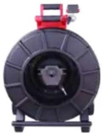
100' Flexible Pipeline Inspection Reel Overview
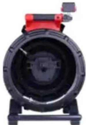
natural_image
Close-up of a black industrial fan or pump with red handle and mounting base (no visible text or symbols)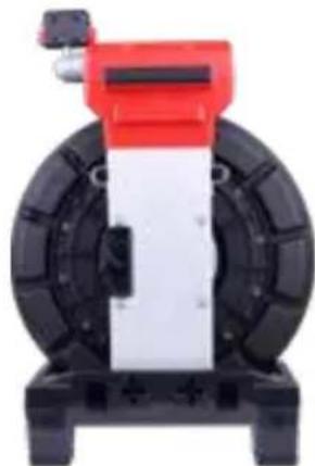
natural_image
Mechanical device with red and black components, no visible text or symbolsFront view Rear view
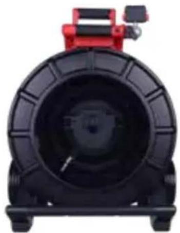
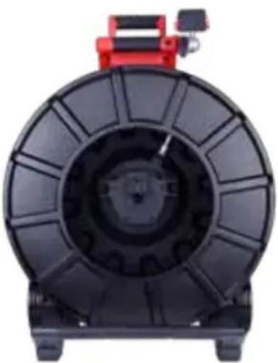
120' Mid-Stiff Pipeline Inspection Reel Overview
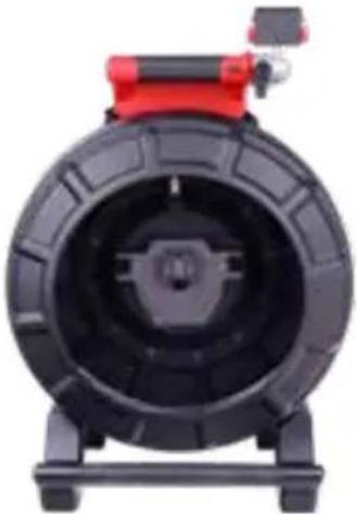
natural_image
Close-up of a black tire with red top mount (no visible text or symbols)
natural_image
Exterior view of a mechanical device with red top and black wheels (no visible text or symbols)Front view Rear view
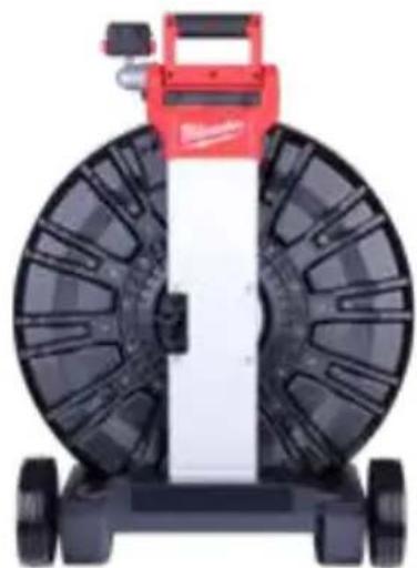
200' Mid-Stiff Pipeline Inspection Reel Overview
natural_image
Top-down view of a black industrial machine with red top and black body (no visible text or symbols)Front view Rear view

natural_image
Top-down view of a red and black industrial machine with wheels and central panel (no visible text or symbols)200' Stiff Pipeline Inspection Reel Overview
natural_image
Top-down view of a black industrial tire with red handle and mounting base (no visible text or symbols)Front view Rear view

natural_image
Exterior view of a black and white wheeled industrial machine with red top (no visible text or symbols)325' Stiff Pipeline Inspection Reel Overview
natural_image
Top-down view of a black industrial fan or motor housing with red mounting bracket (no visible text or symbols)Front view Rear view
natural_image
Top-down view of a mechanical device with black wheels and a red top component (no visible text or symbols)2. M18™ Wireless Monitor
2.1 M18™ Wireless Monitor Overview
The M18 ^™ Wireless Monitor provides viewing, recording, and playback functions of video and picture files. During the recording of videos audio comments can be captured through the internal microphone, and text comments can be added via the Labels feature.
Note that the Wireless Monitor or tablet running the Milwaukee ^ Pipeline Inspection App must be connected to the M18 ^TM 500GB Control Hub in order to create a video recording or capture pictures. Both the video and picture files are stored in the Control Hub Internal Drive.
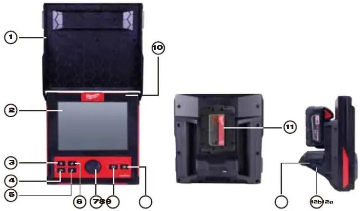
| 1. Sunshield 7. Navigation Dial | ||
| 2. LCD 8. Record video button | ||
| 3. Power button 9. Picture capture button | ||
| 4. Back Button 10. Internal microphone | ||
| 5. Microphone button 11. M18TM Battery mounting area | ||
| 6. Distance reset button 12. | 12a USB-A port12b USB-C port | |
⚠ WARNING To reduce the risk of short circuits, do not allow the battery to contact corrosive or conductive fluid when setting the tool or battery down.
2.2 Setup of the M18 ^TM Wireless Monitor
This section of the manual covers setting up the features and options of the M18 ^™ Wireless Monitor. Mounting the Wireless Monitor to the Pipeline Inspection Reel is covered in section 4.6 of this manual.
2.2.1 Power on/off
Press the Power Ⓓ button on the M18™ Wireless Monitor. The buttons and navigation dial will illuminate, showing that the power is on. The Wireless Monitor icon will appear in the status bar of the LCD along with the battery state.
2.2.2 M18 ^TM Wireless Monitor First Time Setup
All the settings are saved into the M18 ^™ Wireless Monitor's memory and will remain there until changed. Note that the settings will be lost if the unit is reset to factory defaults or by formatting the M18 ^™ 500GB Control Hub Internal Drive. The Pipeline Inspection Reel with camera does not need to be connected to for the first-time setup.
These initial Wireless Monitor settings will set the Units of distance measurement, Date & Time formats, Sonde frequencies, Video, and Image quality, Connection Settings and Language.
These settings can also be performed through a tablet running the Milwaukee ^® Pipeline Inspection App.
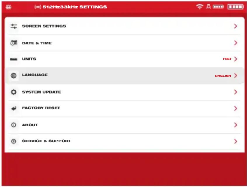
2.2.3 Navigating through the Settings Menu

Navigation Dial - Turn the navigation dial clockwise or counterclockwise to move through the menus. While rotating the Navigation Dial, the position/menu items will be highlighted by the red cursor line.
Press the Navigation Dial to select and accept the setup menu options.

Back Button - Pressing the Back button while in any menu or sub-menu will take the screen back to the previous menu. Press the Back Button repeatedly to return to the main viewing screen.
2.2.4 Setting the M18™ Wireless Monitor Language
It is recommended to set your Language first so that the other menus can be easily read and understood.
- Turn the Navigation Dial to Settings, press the navigation dial.
- Turn the navigation dial to Language, press to enter the Language sub-menu.
- Turn the navigation dial to select the desired Language and press the navigation dial.
- Turn the navigation dial and press on OK to start the Language change.

- The system will reboot and start in the Language selected.
2.2.5 Setting the Date & Time
The system offers Date Formats of MM/DD/YYYY, DD/MM/YYYY and YYYY/MM/DD with 12-Hour or 24-Hour Time Formats.
- Turn the navigation dial to Settings, press the navigation dial.
- Turn the navigation dial to Date & Time, press to enter the Date & Time sub-menu.
- Turn the navigation dial to Date Format, press the navigation dial. Use the navigation dial to select the desired Date Format and press the navigation dial to accept. Repeat the same steps selecting the Date Format.
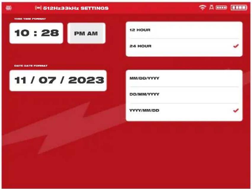
- Now use the navigation dial to enter the Date and Time values.
- Turn the navigation dial to select Save and press the navigation dial.
The Date & Time are now set, and you will be returned to the Settings menu.
If using a tablet running the Milwaukee® Pipeline Inspection App, the Date & Time are taken from the tablet.
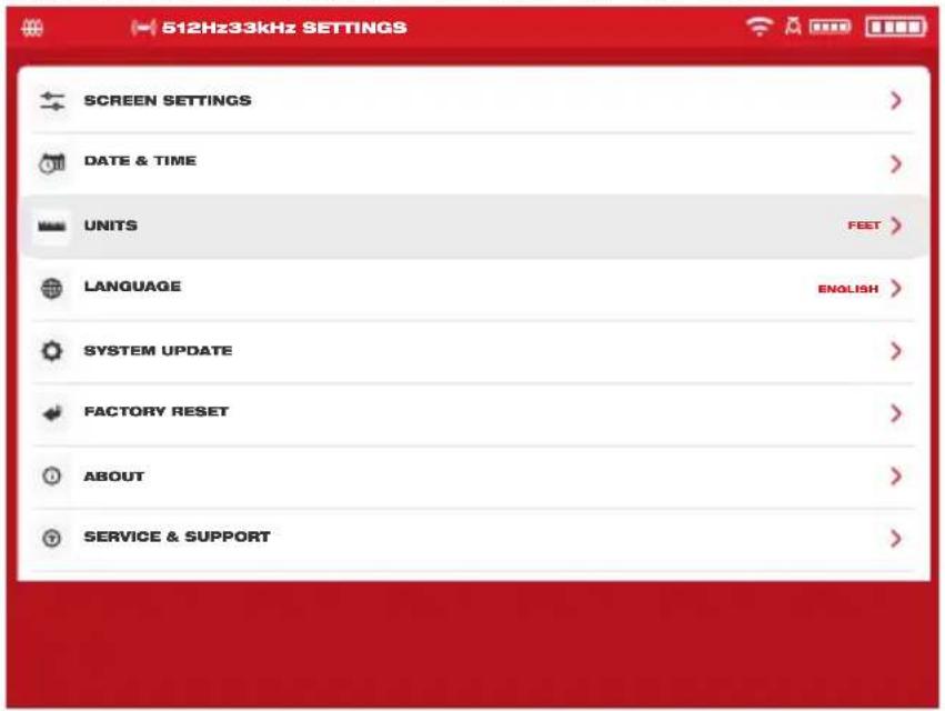
2.2.6 Setting the Units of Measure
- Turn the navigation dial to Settings ⚙, press the navigation dial.
- Turn the navigation dial to Units, press to enter the sub-menu.
2 M18 ^TM Wireless Monitor
- Turn the navigation dial to select Feet or Meter and press the navigation dial.
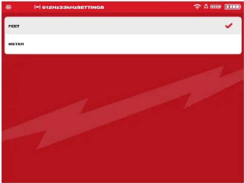
The Units of measures are now set, and you will be returned to the Settings menu.
2.2.7 Setting the Sonde Frequency
- Turn the navigation dial to Settings ☐, press the navigation dial.
- Turn the navigation dial to Sonde Frequency, press to enter the sub-menu.
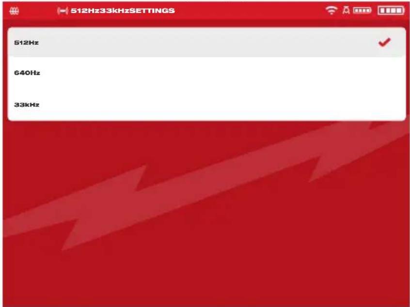
- Turn the navigation dial to select the desired sonde frequency of 512Hz, 640Hz or 33kHz and press the navigation dial. The sonde frequency is now selected and you will be returned to the settings sub-menu.
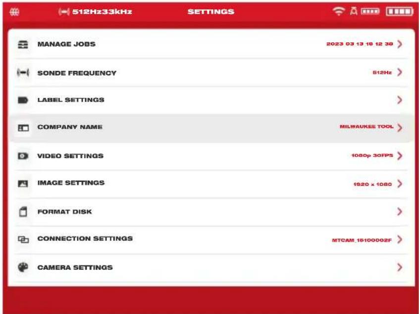
2.2.8 Setting the Company Name
This setting saves a Company Name in the system's memory. The Company Name will splash on the video recordings start for 5 seconds and appear in all JPEG images.
- Turn the navigation dial to Settings ☐, press the navigation dial.
- Turn the navigation dial to Company Name, press to enter the sub-menu.
- Use the navigation dial to navigate the on-screen keyboard pressing the navigation dial to accept each keyboard character.
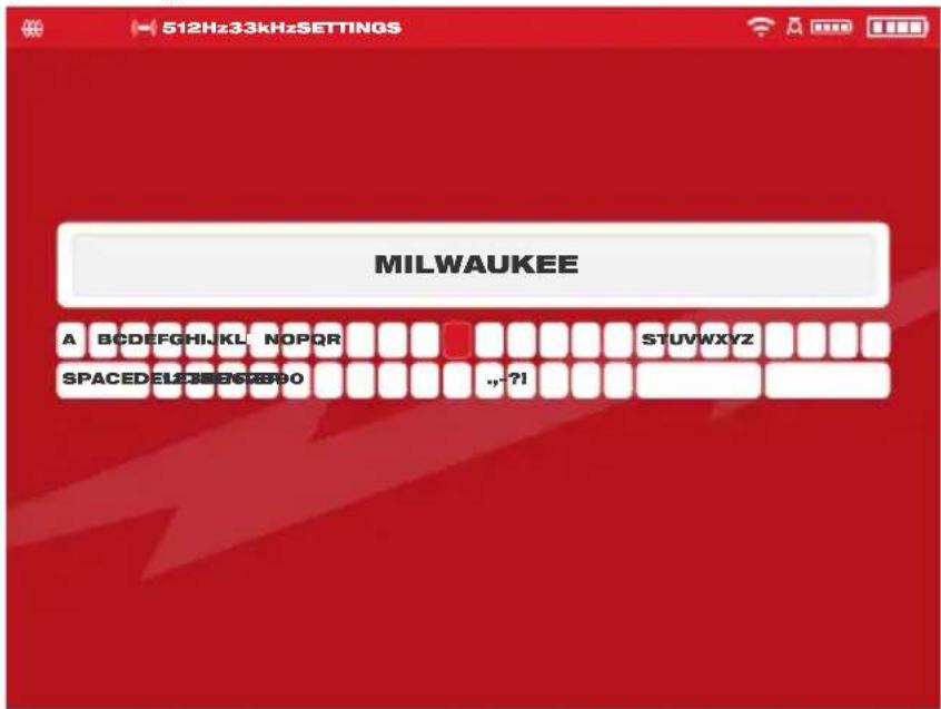
- When finished with the Company Name, navigate to the Enter key, and press the navigation dial.
- Select Save or cancel to continue.
2.2.9 Video and Image Settings
Video Settings
This setting allows for the selection of the video resolution. The video resolution will affect the video quality, which in turn affects the size of the video file.
- Turn the navigation dial to Settings ☐, press the navigation dial.
- Turn the navigation dial to Video Settings, press to enter the sub-menu.
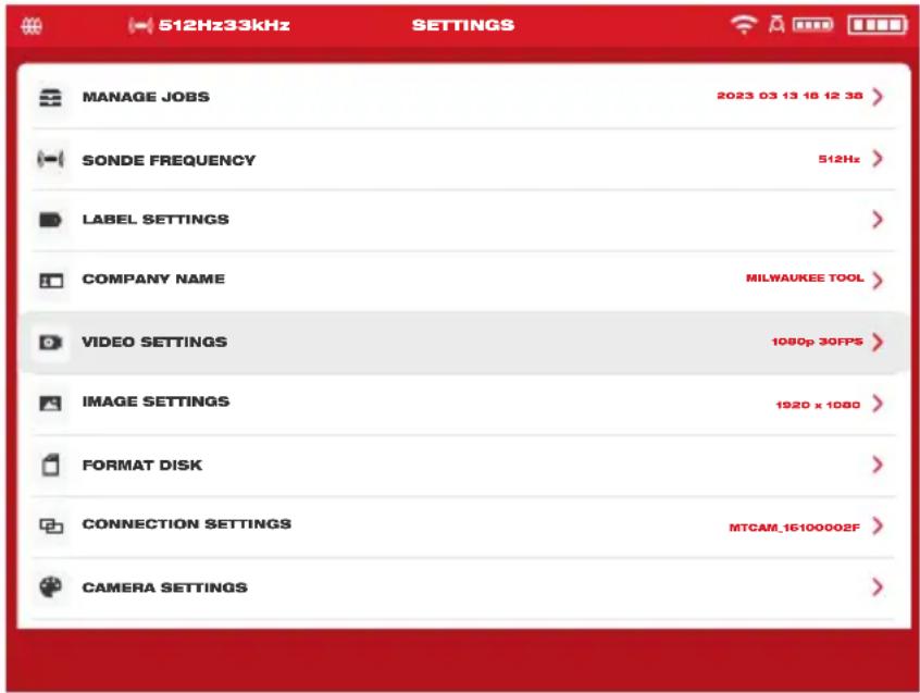
- Use the navigation dial to navigate and select the video resolution and press navigation dial.
- After the resolution has been selected, use the navigation dial to select the frames per second and press the navigation dial.
- After the frames per second choice is selected, the system will return to the Settings menu.
Image Settings
This setting allows for the choice selection of the picture Image dimensions. These dimensions will affect the picture quality, which in turn affects the size of the picture file.
- Turn the navigation dial to Settings ☐, press the navigation dial.
- Turn the navigation dial to Image Settings, press to enter the sub-menu.
- Use the navigation dial to navigate the dimension choices, select one and press the navigation dial.
- After the Image setting choice is selected, the system will return to the Settings menu.
2.2.10 Connection Settings
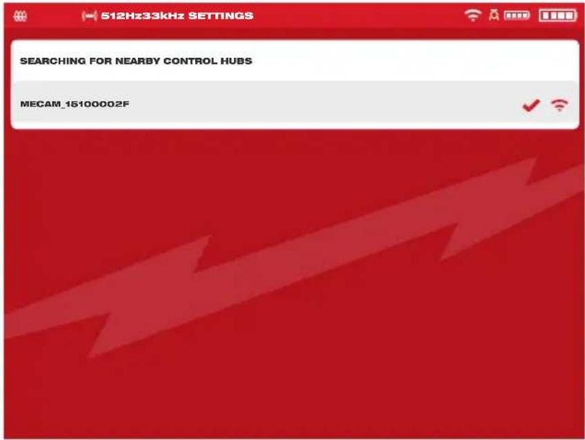
The default connection method for M18™ Wireless Monitor and M18™ 500GB Control Hub is via Wi-Fi. The wireless range between the two units is 200'. If an active Control Hub is within the 200' range, it will show here in the Control Hub List. As a backup, the Wireless Monitor and Control Hub can be connected by using the provided USB-C cable.
First-time Wireless Monitor Paring
- If only one Control Hub is in range, the Wireless Monitor will automatically force pair with it without any user interaction.
- If there is more than one Control Hub in range, the Control Hub List will appear on the Wireless Monitor or Milwaukee® Pipeline Inspection App so the user can choose the desired Control Hub.
• If prompted for a password enter: 29702000
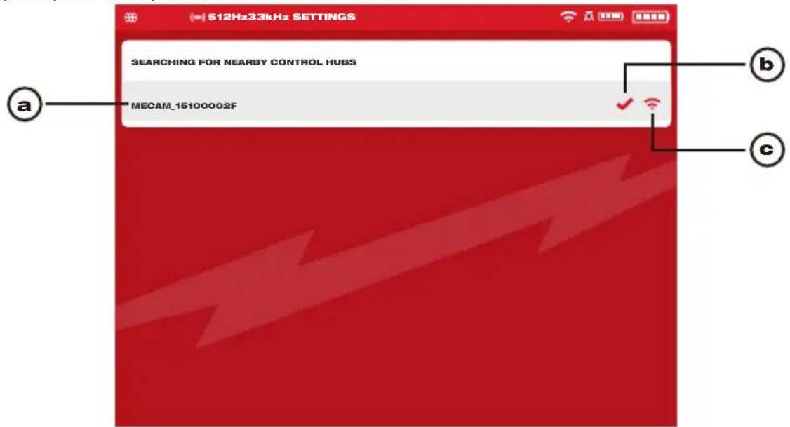
Control Hub List
| a. List of nearby Control Hubs with active Wi-Fi | |
| b. Status – checkmark indicates as connected | |
| c. Signal strength of nearby Control Hubs with active Wi-Fi | |
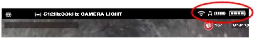
| Battery Capacity – Both M18TM Battery icons have four segments in the icon. Each segment represents 25% of the battery's power capacity. A low battery warning will appear when the capacity reaches 10% | |
 | Cable Connected icon – Shows the Wireless Monitor and Control Hub are connected by a USB-C cable. |
 | Control Hub connection status and wireless signal strength. This icon appears when the Control Hub is connected to the Wireless Monitor by Wi-Fi. |
 | Pipeline Inspection Reel icon – appears when the Wireless Monitor and Control Hub are connected by Wi-Fi or USB-C cable. |
 | M18TM Battery Status icons – The larger icon on the rig represents the Wireless Monitor while the smaller icon on the left represents the Control Hub. |
2 M18 ^TM Wireless Monitor
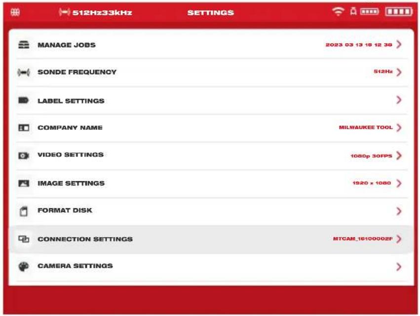
- Turn the navigation dial to Settings ⚙, press the navigation dial.
- Turn the navigation dial to Connection Settings, press to enter the sub-menu.
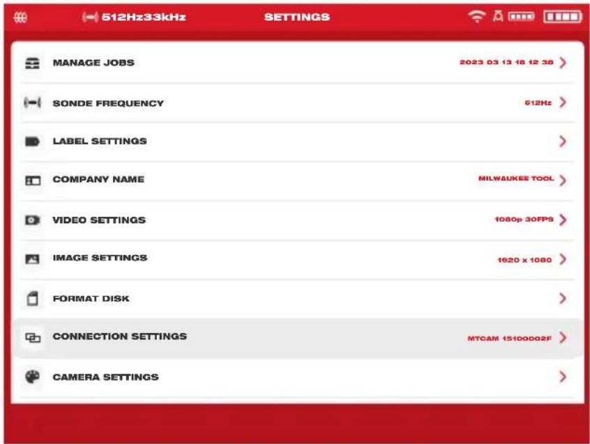
- Use the navigation dial to choose the desired available Control Hub, press to connect.
- After selecting the Control Hub you will be returned to the main menu. The Control Hub name is shown in the menu bar under the Connection Settings.
USB-C Cable Connection – The M18™ Wireless Monitor can also be powered by the M18™ 500GB Control Hub battery via the supplied USB cable. This is extremely useful in some emergency situations in case your battery runs low.
- With the supplied USB-C cable, plug one end into the Control Hub and the other into the Wireless Monitor.
- Confirm the USB-C cable connection by checking the icons in the status bar on the right. When connected by USB-C cable the Wi-Fi icon is now replaced by the cable-connect icon.

The above illustration shows the Wireless Monitor and Control Hub connected by Wi-Fi with a weak monitor battery.

The above illustration shows the Wireless Monitor and Control Hub connected by USB-C cable with the M18 ^™ Battery removed from the Wireless Monitor. The Wi-Fi icon is replaced by the cable-connect icon and the Wireless Monitor battery shows as empty.
2.2.11 M18 ^TM Battery
Both the M18 ^™ Wireless Monitor and M18 ^™ Control Hub are powered by an M18 ^™ Battery. The battery condition of both is always shown in the status bar on the Wireless Monitor screen.
⚠WARNING Recharge only with the charger specified for the battery. For specific charging instructions, read the operator's manual supplied with your charger and battery.

Battery status – the icon to the left represents the battery status of the Control Hub while the icon to the right represents the battery status of Wireless Monitor.
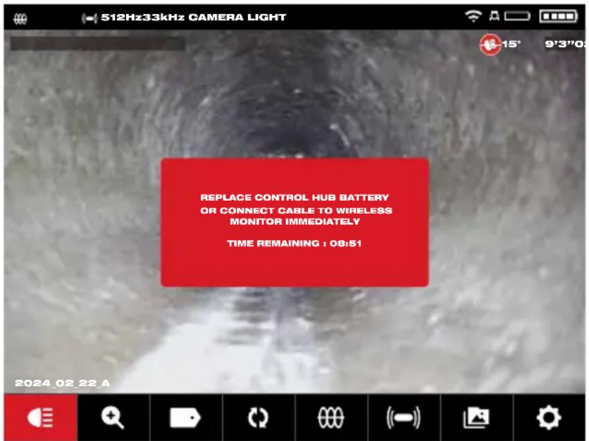
M18 ^™ 500GB Control Hub – The Control Hub is powered by its M18 ^™ Battery which is hot-swappable. If the battery is removed from a running Control Hub, the below message will appear warning that the Control Hub is operating on the internal backup battery for a period of nine minutes. During these nine minutes a charged M18 ^™ Battery must be installed, or a USB-C cable must be attached between the Wireless Monitor and Control Hub. The USB-C cable will now power the Wireless Monitor temporally.
Typical battery life: M18™ Wireless Monitor: Nine hours on a fully charged battery M18™ 500GB Control Hub: Nine hours on a fully charged battery
2.2.12 Setting the LCD Screen Settings
This setting adjusts the M18 ^™ Wireless Monitor LCD screen settings.
- Turn the navigation dial to Settings ☐, press the navigation dial.
- Turn the navigation dial to Screen Settings, press to enter the sub-menu.
- Use the navigation dial to navigate through the menu choices, press the navigation dial to select one.
- Turn the navigation dial left and right to adjust the setting, press the navigation dial to accept it.
- Scroll to the bottom of the sub-menu and press the navigation dial on OK to accept the changes.
2.3 Using the M18™ Wireless Monitor
Many of these instructions also apply to the Milwaukee® Pipeline Inspection App. The Milwaukee® Pipeline Inspection App is available for download from the Apple App Store or at Google Play.
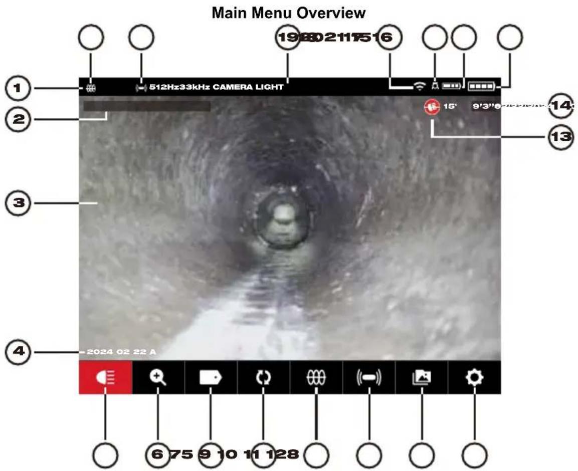
| Ref | Description | Ref | Description |
| 1. | Status bar | 12. | Settings menu |
| 2. | Date and Time stamp | 13. | Pitch Sensing icon |
| 3. | Main viewing area | 14. | Distance out count |
| 4. | Job folder name | 15. | Wireless Monitor battery status |
| 5. | Camera Light | 16. | Control Hub battery status |
| 6. | Zoom & Pan | 17. | Control Hub connection status icon |
| 7. | Labels | 18. | Wi-Fi or cable connection status |
| 8. | Screen Rotate | 19. | Menu location |
| 9. | Line Trace | 20. | Sonde activity status and frequency |
| 10. | Sonde | 21. | Line Trace activity status and frequency |
| 11. | Gallery |
2 M18 ^TM Wireless Monitor
- Status bar – the status bar shows the running options, menu location, connection status and battery status of both the M18 ^TM 500GB Control Hub and M18 ^TM Wireless Monitor. The status bar is always shown regardless of what mode or option is being used.
- Date & Time stamp – the Date & Time stamps are displayed from the system and will appear in all recorded videos image files.
- Main viewing area – is the majority of the LCD and shows the raw video from the camera or videos being played back.
- Job folder name – the name of the folder where the videos and images will be stored.
- Camera Light – brightness of the cameras LED's are controlled here.
- Zoom & Pan – allows for 8 x zooming with vertical and horizontal panning of the video feed.
- Labels – are predefined observations that are splashed on the screen and appear in recorded videos and captured pictures.
- Screen Rotate – will invert the upright picture 90^ with each push of the navigation dial.
- Line Trace – activates the internal transmitter to inject a locate signal onto the push cable.
- Sonde – activates the Sonde transmitter attached at the end of the Pipeline Inspection Reel termination spring to locate the approximate position of the Sonde in the pipe.
- Gallery – Access to the Job video and picture files.
- Settings menu –set user preferences, such as manage jobs, switch language, system updates, etc.
- Pitch Sensing icon – the Pitch Sensing icon shows the current angle of the camera head. The angle is shown from +90° to -90°.
- Distance out count – indicates the length of the cable pushed into the pipe.
- Wireless Monitor battery status – shows the remaining battery level status of the Wireless Monitor.
- Control Hub battery status – shows the remaining battery level status of the Control Hub.
- Control Hub connection status icon – displaying the icon indicates that it is connected to the Control Hub.
- Wi-Fi or cable connection status – display the status of Wi-Fi or USB-C cable connection to the Control Hub.
- Menu location – display the name of the current menu location set by the navigation dial.
- Sonde activity status and frequency – display that the current Sonde is turned on and displays the set frequency.
- Line Trace activity status and frequency – display that the current cable tracking is turned on and displays the set frequency.
2.3.1 Using Jobs
Before creating a video or image file, you can tell the system where to store the files. This is known as creating a New Job or Continue Existing Job. Creating a New Job will setup a container (folder) for both video and image files to be stored in. Continue Existing Job will route the recordings to a Job folder that already exists.
The system will automatically ask which Job to use in certain situations. Whenever the system clock changes to a new day. (after 11:59 PM) Whenever the M18 ^™ Wireless Monitor is restarted. (turned off and on again) Whenever the M18 ^™ 500GB Control Hub is restarted. (turned off and on again)
When the Record button is pressed under the above situations, the Select Job List will appear with options of: New Job With Date And Time or New Job With Name or Existing Job. From this point on the same Job will be used until changed.
When the storage space becomes low a pop-up message will appear prompting to delete some jobs to free up space.
- Turn the navigation dial to Settings ☐, press the navigation dial.
- Turn the navigation dial to Manage Jobs, press the navigation dial to enter the sub-menu. The Manage Jobs sub-menu has five menu options.
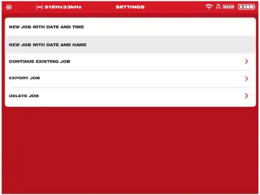
a. New Job With Date And Time – Creates a New Job with the system's date and time as the prefix for all files in this folder.
b. New Job With Date And Name – Creates a New Job with the system's date and time followed by the entered Name for all files in this folder.
c. Continue Existing Job – Will send the new files to an Existing Job previously created.
d. Export Job – Copies the Job from the Control Hub Internal Drive to a Control Hub Thumb Drive.
e. Delete Job – Deletes the Job from the Control Hub Internal Drive.
- Use the navigation dial to navigate the menu choices. Press the navigation dial to enter the desired sub-menu.
- Scroll to the bottom of the sub-menu and press the navigation dial on OK to accept the final changes.
The changes will be saved into memory and the system will return to the main viewing screen.
Creating a New Job
- From the Job's sub-menu use the navigation dial to select New Job With Date And Time or New Job With Name.
If New Job With Date And Time is selected a Job folder with the system current date and time will be created and named YYYY_MM_DD_HH_MM_SS.
If a New Job With Date and Name is selected the next screen will be the on-screen keyboard.

- Use the navigation dial to enter the name of the New Job With Date and Name.
- When finished entering the new job name use the navigation dial to Enter and press the dial.

- Use the navigation dial to select Save and press the navigation dial.
When a New Job With Date and Name is selected a Job folder with the system current date and time will be used as a prefix. The folder is created and named YYYY_MM_DD_NEW JOB NAME.
2.3.2 Creating a Video Recording and Image Capturing
By default, all videos and images recorded are saved to the M18 ^™ 500 GB Control Hub Internal Drive. If a thumb drive is plugged into the Control Hub all videos and pictures can be saved to both the Control Hub Internal Drive and Control Hub Thumb Drive.
Filenames – the file names are automatically created by the system and consist of the year, month, day, time created, and or Job name. This will vary depending on the Job type selected.
If selecting New Job With Date And Time, the filename will look like this: 2019_10_01_12_50_10_2
2019 = Year, _10 = Month, _01 = Day, _12 = Hour, _50 = Minutes, _10 = Seconds and _2 = second file created.
If selecting New Job With Name, the filename will look like this: 2019_10_01_JOBNAME_1
2019 = Year, 10 = Month, 01 = Day, JOBNAME and 3 = third file created.
If a file were saved as a Highlight video, the filename would be followed by "_h".
- Press the Record button on the M18™ Wireless Monitor to start the recording. If this is the first recording of the day or if the Wireless Monitor or Control Hub was restarted, when the record button is pressed the Select Job dialog box will appear to route the recording record to the appropriate Job folder.
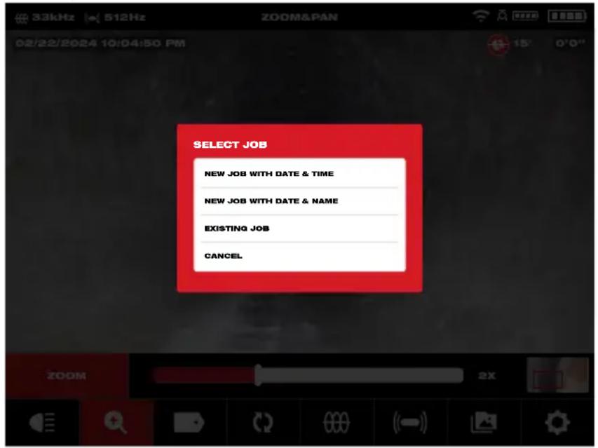
- Choose the desired option and press the navigation dial.
- After the Job option has been selected a flashing recording icon will appear in the upper left corner of the status bar with the video recording length in minutes and seconds and the Camera Lights icon will change to a Pause icon.
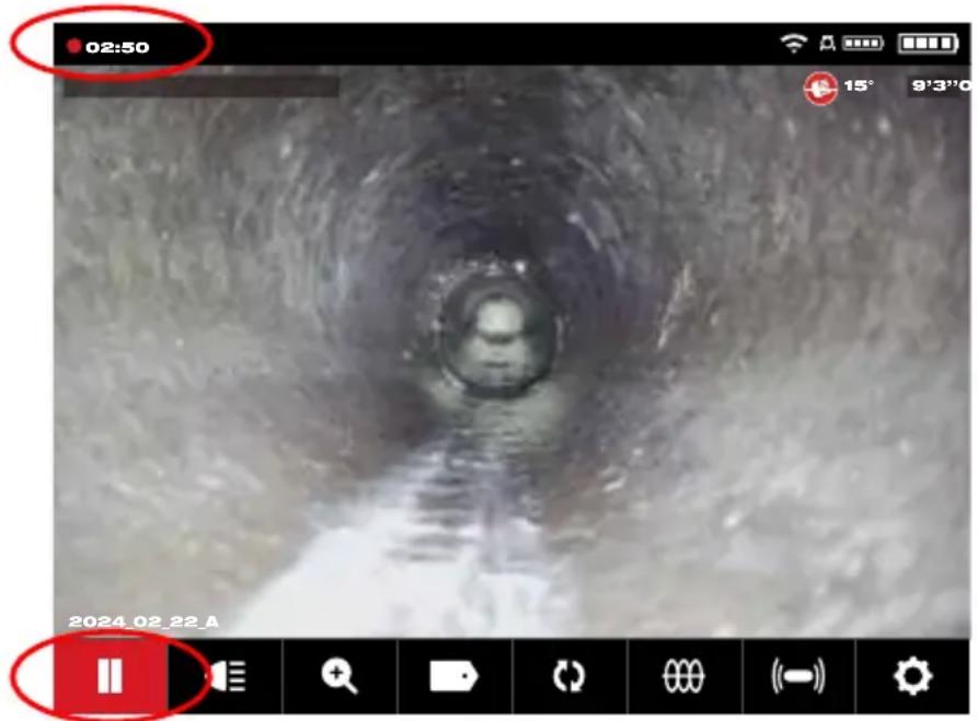
Recording icon, Pause icon and video length
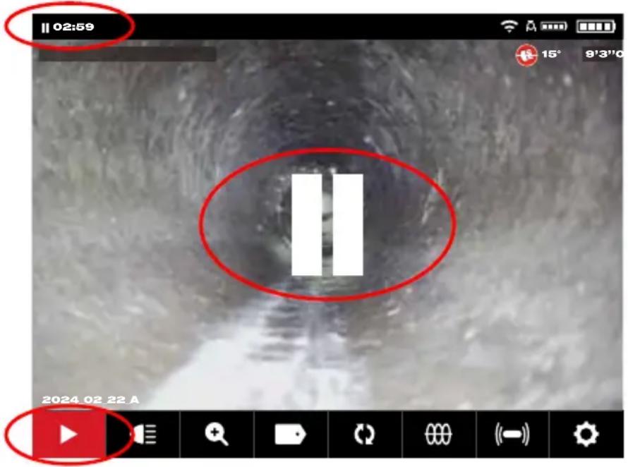
- When a recording video is paused the pause symbol will appear center screen, a Resume icon will show on the bottom left corner and the blinking recording icon in the upper left corner of the screen will change to a blinking pause icon.
- Press the Picture button to capture an image. The screen will flash red for a moment confirming that the image was captured.
At the end of the session press the Record button again to end and save the video file.
Image Files – images can be captured while recording or viewing raw video from the camera. The image will be saved in the same Job folder as the video.
When the Picture button is pressed, the image is captured exactly as it is viewed on the screen. If the picture is in Zoom, Pan or Screen Rotate modes the captured picture will appear as such.
2.3.3 Export Job
The Export Job allows for the copying of files from the M18 ^™ 500GB Control Hub Internal Drive to the Control Hub Thumb Drive.
From within the Gallery 📄 individual or multiple files or Jobs can be exported one at a time.
From the Manage Jobs option, under Settings ☐ entire Jobs can be exported in one session.
Export a Job from the Gallery
- From the Gallery select the desired video or image.
- Use the navigation dial to select Export [↑], press the dial.
- Use the navigation dial to select the export destination of Control Hub Thumb Drive, press the navigation dial. The progress indicator will appear showing the status.
2 M18 ^TM Wireless Monitor
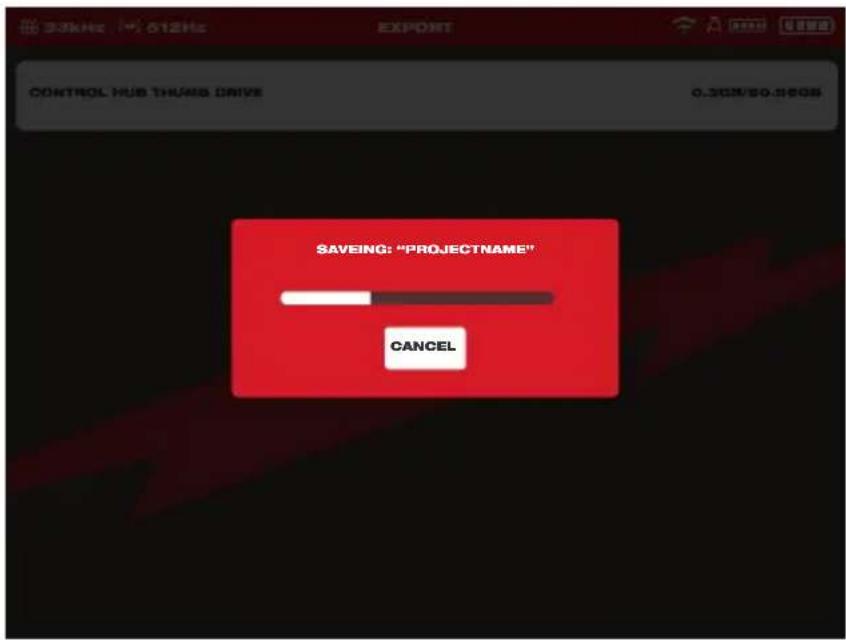
- Wait for the progress indicator to run until completed.
Export multiple Jobs from the Gallery

Gallery view showing three Jobs
- While in the Gallery press and hold the Navigation Dial ● for seven seconds and release it. The top portion of the Job strip will now contain a white check box.
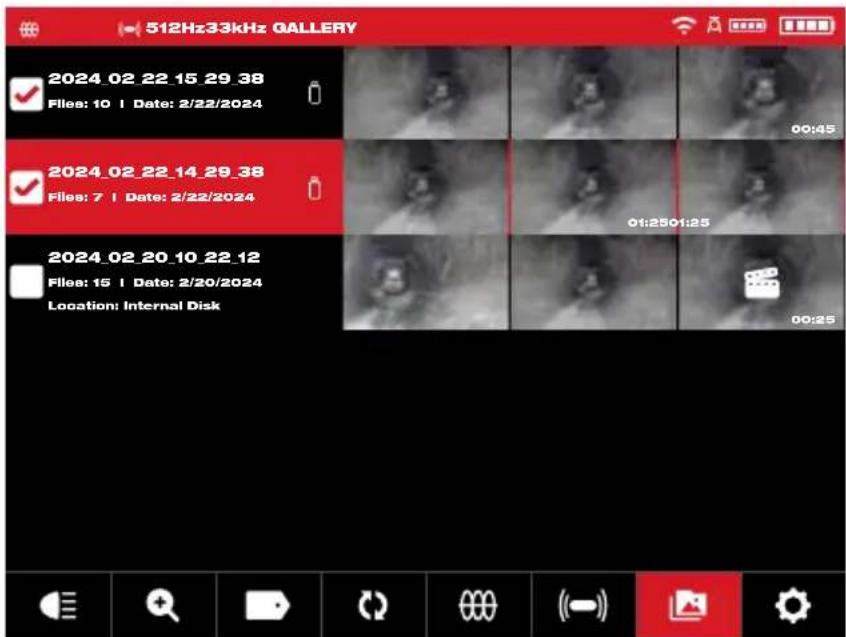
The Gallery view showing selection boxes in the upper left corner.
- Use the navigation dial to select and check the jobs for export.
- Press and hold the Navigation Dial for seven seconds and release. A dialog box will appear with choices of Export, Delete and Cancel.

Multiple job choice dialog box
Export – Pressing Export will bring up the dialog box to export the job(s) to the hubs USB-A drive.
Delete – Pressing Delete will bring up the dialog box to confirm that the files will be deleted. Use the navigation dial to check the jobs for export.
Cancel – Pressing Cancel will step back to the Main Gallery view.
- Press the Back key to return to the main view screen when finished.
Export from within the Settings menu
- From the main viewing screen, turn the navigation dial to Settings ☐, press the navigation dial.
- Turn the navigation dial to Manage Jobs, press the navigation dial.
- Turn the navigation dial to Export Job, press the navigation dial.
- Turn the navigation dial to select the Job to export, press the navigation dial. The export destination of Control Hub Thumb Drive appears.
- Press the navigation dial. The progress indicator will show the status.
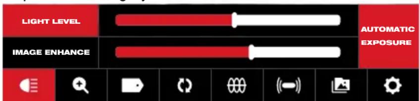
2.3.4 Adjusting the Camera Light
Entering the Camera Light menu gives access to three settings of Light Level, Automatic Exposure and Image Enhance.
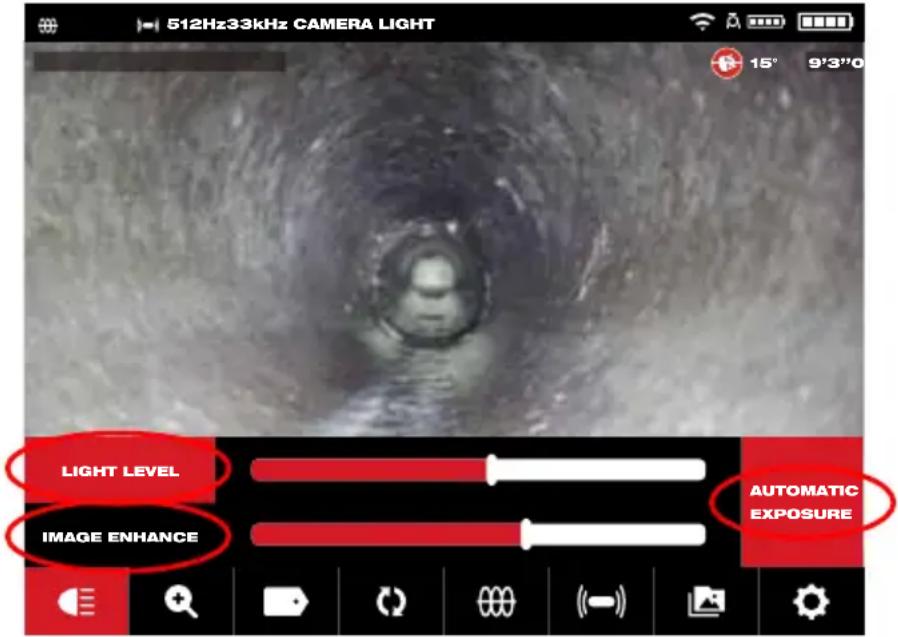
The sub options of Light Level, Automatic Exposure and Image Enhance
- Turn the navigation dial to Camera Ligh, press the navigation dial to enter the Camera Light menu. Upon entering the Camera Light menu the Light Level feature will be active and show a blue outline around the light level indicator.
- Turn the navigation dial to reach the desired light level.
- Press the navigation dial again to accept the light level and move on to the Automatic Exposure option.
- If the Automatic Exposure option is not needed, press the Back button to exit and return to the main viewing area.
2.3.5 Automatic Exposure
Automatic exposure allows the camera to automatically adapt to changes in lighting. Automatic exposure attempts to make the scene appear equally bright regardless of the changes in lighting or other conditions such as reflection or the distance to objects during the video recording. Turning off the automatic exposure locks the current camera exposure allowing the user to adjust the lighting intensity to obtain a better picture in extreme lighting/pipe conditions/environment. The Automatic Exposure is active (on) by default and shown as active by the red box to the right of the level scales.
Note: The Auto Exposure feature is available in the newer HDR series camera heads. If the Automatic Exposure box is greyed out this feature is not available.
This illustration shows the Automatic Exposure as active

This illustration shows the Automatic Exposure as inactive

This illustration shows the Automatic Exposure as not available
- Turn the navigation dial to Camera Light ☐, press the navigation dial to enter the Camera Light menu. Upon entering the Camera Light menu the Light Level feature will be active and show a blue outline around the light level indicator.
- Press the navigation dial two times to reach the Automatic Exposure box which will turn red.
- Press the navigation dial again to turn off the Automatic Exposure. A line will show through the titled box.
- Turn the navigation dial to the right to exit the Automatic Exposure setting and move to the Image Enhance option.
- If the Image Enhance option is not needed, press the Back button to exit and return to the main viewing area.
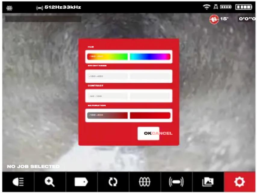
2.3.6 Image Enhance
The Image Enhance feature allows the LCD display to show more detail and depth from the camera head in different textures and colors of pipes. The Image Enhance feature automatically adjust the LCD's display brightness and contrast settings based on the light from the camera head.
- Turn the navigation dial to Camera Light press the navigation dial.
- Turn the navigation dial to reach the desired light level.
- Press the navigation dial three times to move to Image Enhance.
- Use the navigation dial to move the Image Enhance scale stopping on the best result. Press the navigation dial to accept the setting.
- Press the Back button to exit and return to the main viewing area.
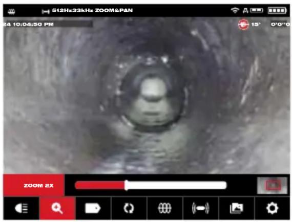
2.3.7 Zoom & Pan
- Turn the navigation dial to Zoom & Pan + , press the navigation dial.
- Zoom – Turn the navigation dial to Zoom, press the navigation dial.
- Turn the navigation dial to reach one of eight Zoom levels and press the navigation dial. Turn the navigation dial to Zoom in or out, the graphic to the far right will grow or shrink according to the Zoom level.
- Press the navigation dial.
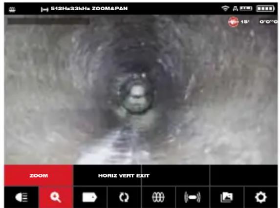
Standard Zoom Zoom X 2
- Pan – Turn the navigation dial to Horiz or Vert and press the navigation dial.
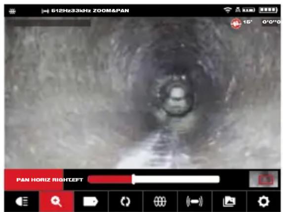
Select Horiz or Vert and press the navigation dial
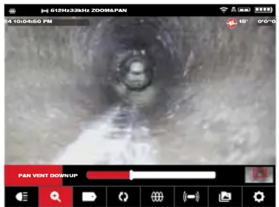
Pan Horizontal and Vertical – Panning horizontally moves the position in the image in right and left directions. Panning vertically moves the position in the image in up and down directions. In both options as the navigation dial is turned in Pan Horiz. or Pan Vert. the graphic to the far right on will move with the vertical or horizontal panning showing where you are located within the image.
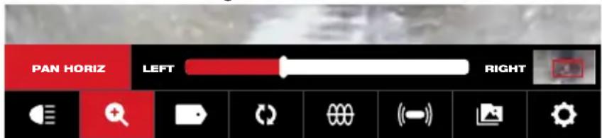
Pan location reference

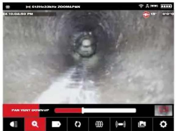
Example of Panning Horiz. to the left Example of Panning Vert. up
- Press the Back button to exit and return to the main viewing area.
2.3.8 Screen Rotate
- Screen Rotate – will invert the upright picture 90^ with each push of the navigation dial. This is helpful while using the reel in the horizontal position, and the monitor may not be in an upright position. Turn the navigation dial to Rotate ( ), press the navigation dial to start the screen Rotate option.
- With each press of the navigation dial, the screen will Rotate 90° to the right.
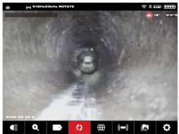
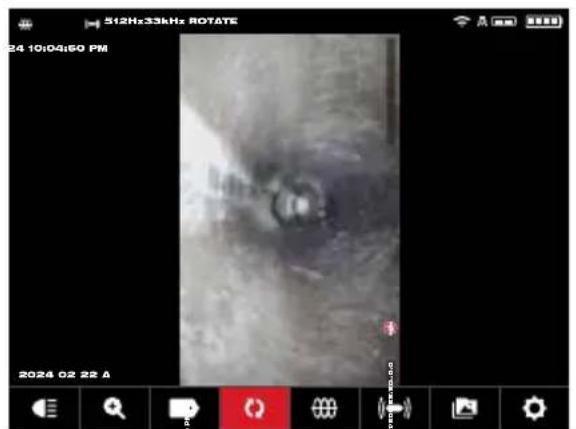
0 Degrees (default) 90-Degree position
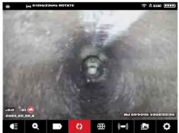
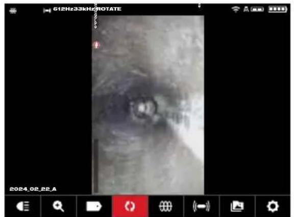
180-degree position 270-degree position
While viewing a rotated image on the Wireless Viewer the text will follow the rotation angle. The captured image in the Gallery will show the text in an upright position.
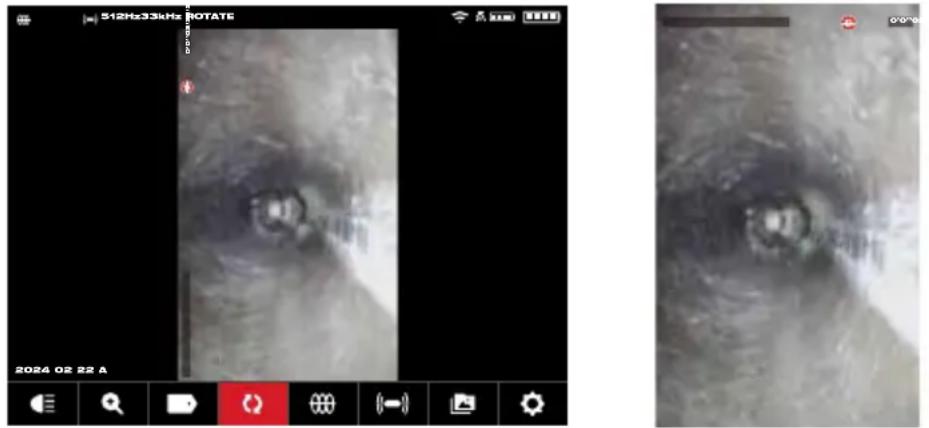
View in Wireless Monitor JPEG file view
Note: The screen will remain in a Rotate position until it is adjusted back to the default in this setting.
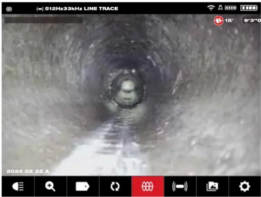
2.3.9 Line Trace
Line Trace – activates the internal transmitter to inject a locate signal onto the push cable. The length of deployed push cable can now be located and traced above ground with a locator set to the matching Line Trace frequency. The M18 ^™ 500GB Control Hub must be properly grounded when using the Line Trace feature. See section 3.3.3 in this manual covering the Grounding Post for additional information.
- Turn the navigation dial to Line Trace, press the navigation dial.
- Turn the navigation dial to select a Line Trace frequency of 33kHz or 83kHz and press the navigation dial.
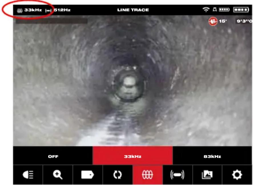
The Line Trace is now active, and the Line Trace icon with selected frequency will appear in the status bar.
- Deactivate the Line Trace mode by turning the navigation dial to Line Trace 000, press the navigation dial and select Off, and press.
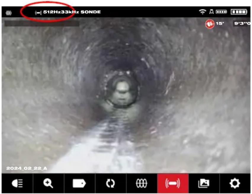
2.3.10 Sonde
Sonde – activates the Sonde transmitter attached at the end of the Pipeline Inspection Reel termination spring to locate the approximate position of the Sonde in the pipe. The choice of the Sonde frequency was selected during setup and can be changed by going to Settings, and then Sonde Frequency. The choices of Sonde frequencies to use are 33kHz, 512Hz or 640Hz.
33kHz – is useable in non-metallic pipes.
512Hz – is mostly used in North America and is useable in both metallic and non-metallic pipes.
640Hz – is mostly used in Europe and is useable in both metallic and non-metallic pipes.
a. Turn the navigation dial to Sonde ( ((—)) ) and press the dial. The Sonde is now active, and the Sonde icon will appear in the status bar along with the frequency.
b. To deactivate the Sonde press the navigation dial when it shows the Sonde icon selected.
2.3.11 Gallery Overview
In the Gallery, all the videos and pictures are shown organized in folders and stored for reviewing, editing, exporting or deleting.
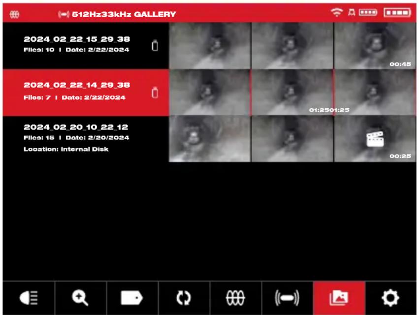
Gallery view showing two jobs
In the Gallery view, each Job folder is shown with the date and number of files in the job. The Saved Locations labels Gallery show if the files are located on the Control Hub Internal Drive or Control Hub Thumb Drive.
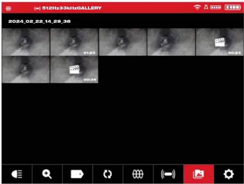
When entering the job folder, the individual files are shown with thumbnails. The highlighted video thumbnail displays an icon in the center and the video length in the lower right corner. The recorded video displays the video length in the lower right corner.
Tapping on a thumbnail in the Gallery will launch that thumbnail into a full-size picture or video.
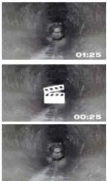
A standard recorded video file
A highlighted video file
A JPEG picture file
Options for files in the gallery include:
| Playback |  | Plays back a recorded video file or views a jpg picture file |
| Pause |  | Pauses and resumes the playing video |
| RW/FF |  | Rewind and fast forward |
| Trim |  | Edits the video length by selecting portions of the video to keep and portions to trim |
| Record Audio |  | Add audio comments on top of video files |
| Speaker Volume |  | Adjust the playback volume of video files |
| Export |  | Copies the files from the Control Hub Internal Drive to the Control Hub thumb drive or mobile device |
| Delete |  | Deletes the file(s) from the Control Hub Internal Drive or Control Hub thumb drive |
| Exit |  | Exits the Gallery menu and returns to the Job folder |
2.3.12 Playback Highlights
When Labels (section 2.3.18) or audio comments (section 2.3.15) are added to recording videos via the internal microphone, these parts of the video where the label or audio was added are marked with a highlight marker in the video playback progress bar. These highlight markers are shown with a white bar in the playback progress bar.

The progress bar with highlights shown
The highlighted files are shown in the gallery with the Scene Marker icon 📁 in the center of the thumbnail. The highlight video is a shorter length video because the video forwards fast while playing and only slows to normal speed when the highlighted segments with areas of interest are played.
This is extremely useful while reviewing videos as it shows a place of interest of comment in the video to fast forward or rewind.
2.3.13 Playing videos and viewing pictures
- Turn the navigation dial to Gallery 📄, press the navigation dial to view the sub-menu.

Gallery sub-menu
-
Turn the navigation dial to the folder whose files are to be accessed, press the navigation dial.
-
Turn the navigation dial to select a file, press the navigation dial.
Play a video file – Select the video file using the navigation dial, press the dial to start the playback. Use the pause function to pause and resume playing the video file. Viewing a picture file – Select the picture file the navigation dial to view the picture.
- When finished viewing the video or picture, rotate the navigation dial to Exit and press the navigation dial to return to the folders sub-menu. Use the back key to return to the main viewing screen.
Pressing the Image capture button while playing a video will save the image to the Gallery.
2.3.14 Rewind and Fast Forward
Use the rewind and fast forward feature to move through a playing video.
- From the Gallery use the navigation dial to select a video to play, press the navigation dial.
- Select the RW/FF (rewind/fast forward) ▶▶I menu option and press the navigation dial.

-
Turn the navigation dial clockwise to fast forward or counterclockwise to rewind. While turning the navigation dial, the red bar progress indicator shows the place in the video recording. Each turn of the navigation dial advances or rewinds the video.
-
Press the navigation dial again to return to the sub-menu, scroll to Exit and press the navigation dial to exit to the Gallery.
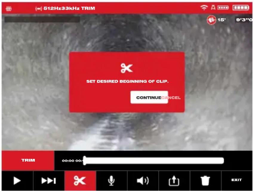
2.3.15 Trimming Video Files
Use the Trim feature to edit the length of a video and save it as a new file.
- From the Job folder in the Gallery use the navigation dial to select the video file to Trim, press the navigation dial.
- Select the Trim ✗ menu option and press the navigation dial.
- Press Continue at the "Set desired beginning of clip message". Turn the navigation dial clockwise while watching the advancement of the video to select the Trim starting point, press the navigation dial.
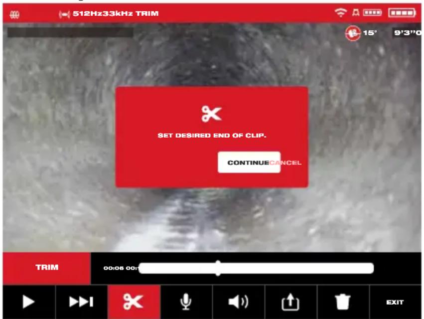
- Press Continue at the "Set desired end of clip" message. Turn the navigation dial counterclockwise while watching the advancement of the video to select the Trim ending, press the navigation dial.
- Press Trim at the "Confirm trim" message, this will create a new trimmed video.
2 M18 ^TM Wireless Monitor
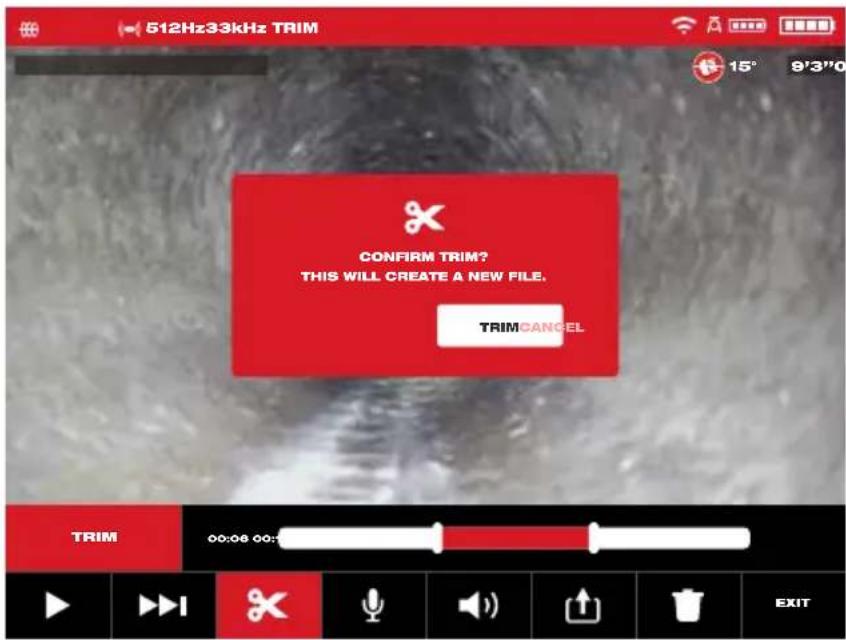
- Use the on-screen keyboard to enter the new file name, when finished with the new file name navigate to Enter and press the navigation dial.

- Now select Save to save the new trimmed file. A dialog box will appear showing the file saving progress.
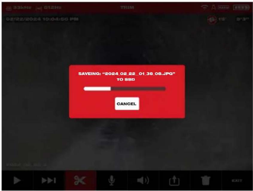
- The new trimmed file is now placed in the same Job folder as the original file.
2.3.16 Recording Audio
This feature adds audio comments to recording videos or to existing videos already in the gallery. This is useful to add audio annotations to accompany any labels used in the video or if something new was spotted during the review of the video. When adding annotations to an existing video file, the original file will remain the same, and a new file will be created with the annotations. You will have to name this new file at the end of the procedure.
Note that any Highlights from the original video will not be saved in the newly created video you are adding an audio comment to.
- From the Gallery select the desired video to add annotations to.
- Select Play▶ to watch the video, press Pause ▶ at the spot to add the annotation. Use the RW/FF ▶▶ feature to reach highlighted parts of the video.
- Turn the navigation dial to the Record Audio 🖱️ icon and press navigation dial to activate the microphone. You can also press the Microphone Button 🖱️ directly to activate the microphone. Note that the Microphone Button 🖱️ will glow red when active.
- Speak clearly facing the internal microphone (located in the top left corner of the M18 ^™ Wireless Monitor) and be in the range of 48 inches from it.
- Press the navigation dial again (which is currently on Microphone) to deactivate the microphone.
- Turn the navigation dial to select Save & Exit, press the navigation dial.
- Select OK on the message to set a name for the new annotated file.
- Use the on-screen keyboard to enter a name for the file, navigate to and select Return, then select Save.
- Wait for the progress indicator to run until completed.
2.3.17 Speaker Volume
The Speaker Volume can be adjusted during video playback and while editing videos.
- From the Gallery select the desired video.
- Use the navigation dial to select Speaker Volume 📁), press the navigation dial.
- Use the navigation dial to set the Speaker Volume, then press the navigation dial and the system will return to the video sub-menu.
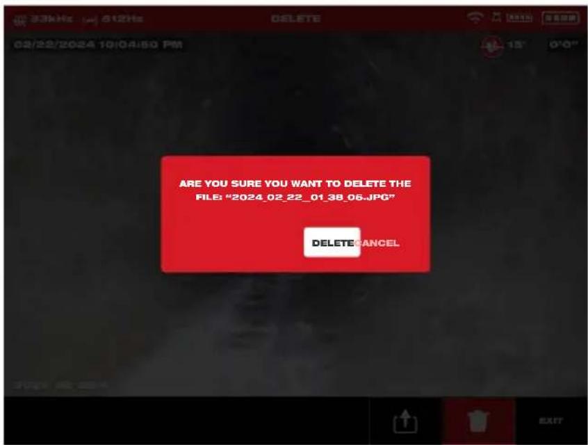
2.3.18 Delete Files
From within the Gallery 📂 individual files can be deleted one at a time.
From the Settings menu, select Manage Jobs and entire folders of jobs can be deleted in one session.
Deleting files from the Gallery
-
From the Gallery ☐ select the desired Job folder, then desired video folder from within the Job.
-
Use the navigation dial to select Delete, press the navigation dial.
2 M18 ^TM Wireless Monitor
- Acknowledge the deletion pop up message by pressing the navigation dial when Delete is selected.
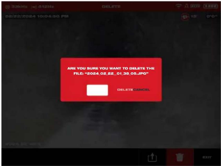
The file has been deleted, and the system returns to the gallery sub-menu.
Deleting Files from within the Settings menu
- From the main viewing screen, turn the navigation dial to Settings ☐, press the navigation dial.
- Turn the navigation dial to Mange Job, press the navigation dial.
- Turn the navigation dial to Delete Job, press the navigation dial.
- Turn the navigation dial to select the Job to delete, press the navigation dial.
- Acknowledge the deletion pop up message by pressing the navigation dial when Delete is selected.
The Job folder and files within it have been deleted, and the system returns to the Manage Jobs sub-menu. Press the Back key to exit the sub-menu, press again to return to the main viewing screen.
2.3.19 Using Labels
Labels are predefined observations that are splashed on the screen and appear in recorded videos and captured pictures. When a Label is selected, it will appear on the screen for 15-seconds and then disappear.
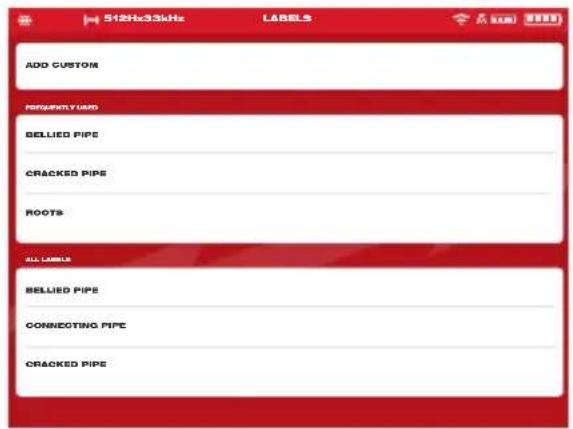
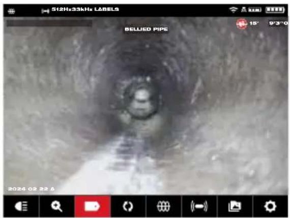
List of created Labels The Label shown splashed on the screen
In the Labels sub-menu, the option of Add Custom allows the creation of a new label. Also shown on the screen is the list of Frequently Used and All Labels.
After a label is used more than five times, it will automatically be added to the Frequently Used list of labels.
Creating and saving a new label
- Turn the navigation dial to the Settings option, press the navigation dial to enter the Settings sub-menu.
- Turn the navigation dial to the Labels Settings option, press the navigation dial to enter the sub-menu.
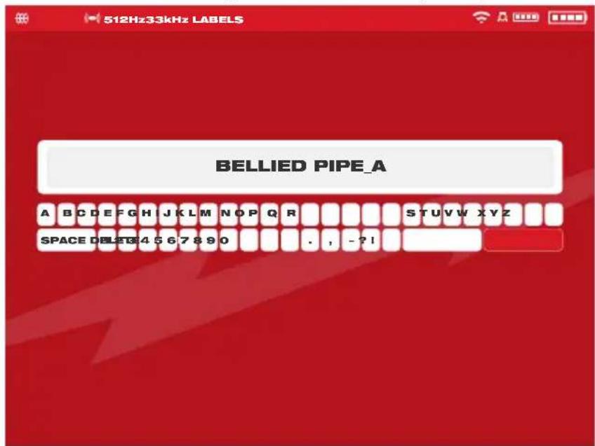
- Select Add Custom and press the navigation dial.
- Use the navigation dial to navigate the on-screen keyboard pressing the navigation dial to accept each keyboard character.
- When finished with the label, navigate to the Enter key and press the navigation dial.
2 M18 ^TM Wireless Monitor
- Select Save or Cancel to the confirmation message and press the navigation dial to continue.
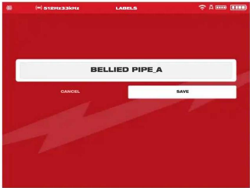
The label now appears in the All Labels list and is available to use with the Labels option from the main viewing screen.
- Press the Back ← key to return to the Labels sub-menu, press again to return to the main viewing screen.
Editing labels
Previously created Labels can be edited or deleted with this option.
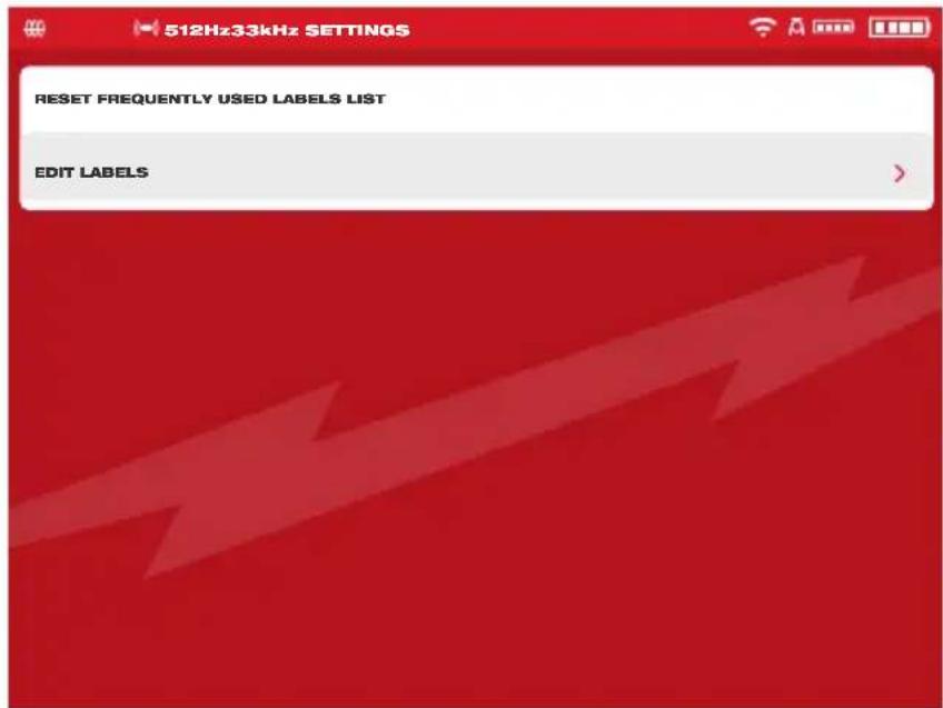
- Turn the navigation dial to Settings ☐, press the navigation dial.
- Turn the navigation dial to Labels Settings press the navigation dial to enter the sub-menu.
- Select Edit Labels and press the navigation dial.
- Use the navigation dial to navigate to and select the label for editing or deletion, press the navigation dial.
- Select Edit or Delete and press the navigation dial.
Editing – will bring up the on-screen keyboard, make the edits and navigate to the Enter key, press the navigation dial, then select Save to save the label changes.
Follow the instructions under "Creating and saving a new label" to edit and save.
Delete – Will delete the label from memory.
- Press the Back key to return to the Labels sub-menu, press again to return to the main viewing screen.
Reset Frequently Used Labels List
This will remove previously used labels currently in the Frequently Used Labels List.
- Turn the navigation dial to Settings ☐, press the navigation dial.
- Turn the navigation dial to the Labels Settings option, press the navigation dial to enter the sub-menu.
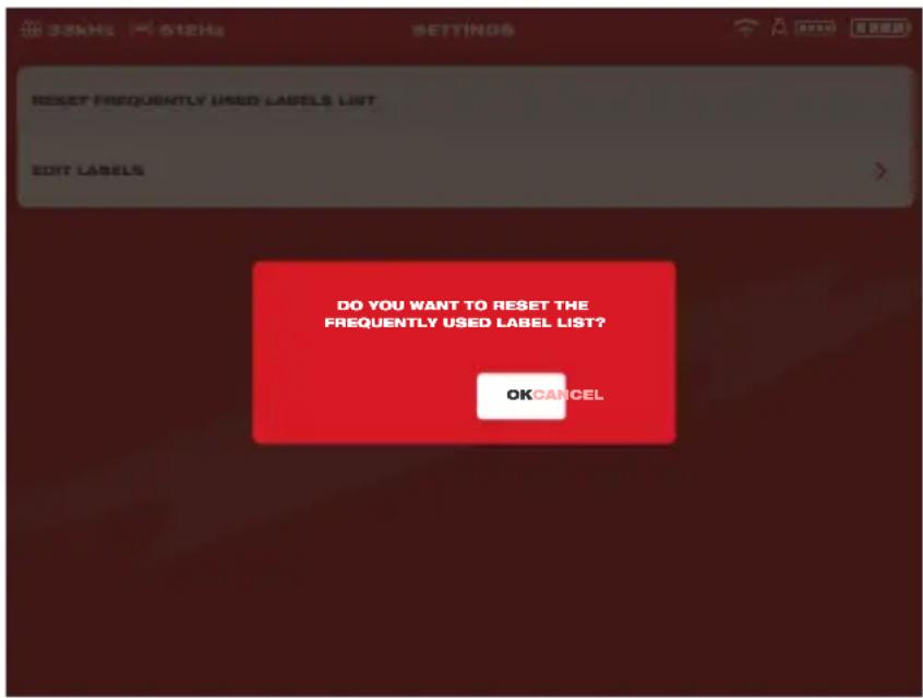
- Select Reset Frequently Used Labels List and press the navigation dial.
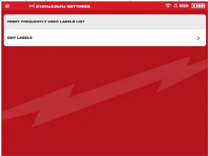
- Acknowledge the on-screen message by pressing the navigation dial again or turn the navigation dial to select Cancel.
2.3.20 Pitch Sensing
The Pitch Sensing feature shows the current angle of the camera head. The angle is shown from +90^ to -90^ .
The Pitch Sensing icon is color-coded to show the pitch and a numeric pitch value.
 | 90° | A Red icon shows an upward-pitch. The maximum upward-pitch angle is 90°. |
 | 0° | A Blue icon to show when the pitch is level at 0°. |
 | -90° | A Green icon shows a downward-pitch. The maximum downward-pitch angle is -90°. |
2.4 Factory Reset & Firmware Updates – M18 ^TM Wireless Monitor
2.4.1 Factory Reset - M18™ Wireless Monitor
Performing a factory reset will reset the M18 ^™ Wireless Monitor to the factory defaults. On the Wireless Monitor, the functionality that will reset to the factory default will be:
- Backlight settings back to default
- Wireless Monitor /Control Hub connection settings
-
System language
-
Turn the navigation dial to Settings ☐, press the navigation dial.
- Turn the navigation dial to Factory Reset press the navigation dial to enter the sub-menu.
-
Select Factory Reset Wireless Monitor and press the navigation dial.
-
Read and acknowledge the factory reset message by selecting OK.

The factory reset is now complete, and the system is returned to the Factory Reset sub-menu.
2.4.2 Firmware Updates - M18™ Wireless Monitor
Firmware updates are periodically released to introduce new features and optimizations. Before updating a system, go to the About section (found at the bottom of the Settings menu) of the Settings menu and make a note of the current firmware revisions in the system.
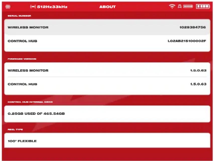
System information is shown in the About screen
Firmware updates are found at www.milwaukeeetool.com.
- Go to the Milwaukee ^® website and click the SUPPORT link, then click on MANUALS AND DOWNLOADS.
- Enter the CATALOG NUMBER, which can be found on the front cover of this manual, in the search box.
- Select SOFTWARE DOWNLOAD and then click on GO.
- Drag the downloaded firmware update file onto a USB thumb drive or right mouse click and select copy, then paste the firmware update file to a USB thumb drive.
- Insert the USB stick containing the firmware update into the M18™ Wireless Monitor's USB-A port.
- Turn the navigation dial to Settings press the navigation dial.
2 M18 ^TM Wireless Monitor
-
Turn the navigation dial to the System Update option, press the navigation dial to enter the sub-menu.
-
Select Wireless Monitor and press the navigation dial. The file name of the update should be seen in this window.
Press the navigation dial when the update file is highlighted in red to begin the update.
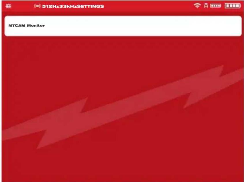
Example of a Wireless Monitor Update file
- Read and acknowledge the warning message by selecting OK.

- A progress indicator will appear showing the progress of the update.

- A confirmation message will appear when the update is complete, and the system will reboot.

- Go to the About option in the Settings menu to confirm that the firmware revision numbers have been updated.
2.4.3 M18™ 500GB Wireless Monitor System Update – Over the Air
This section covers updating the M18™ 500GB Wireless Monitor using the Pipeline Inspection App. This is an over the air firmware update and does not require using a USB thumb drive.
⚠ WARNING Upgrading the M18™ 500GB Wireless Monitor can only be completed after upgrading the M18™ 500GB Control Hub with the Pipeline Inspection App.
When the latest Control Hub firmware is installed using the Pipeline Inspection App, the firmware of Wireless Monitor is also downloaded into the hub. After upgrading the Control Hub, the Wireless Monitor connected to the Control Hub will automatically detect that the firmware of the current Wireless Monitor is the latest version. If it is not the latest version, it will be automatically upgraded to the latest version.
- Use the Pipeline Inspection app to complete upgrading the Control Hub first.
- Connect the Wireless Monitor to the Control Hub. The Wireless Monitor will automatically detect whether the firmware is up-to-date. If it is not, it will be upgraded automatically.

- After upgrading the Wireless Monitor, the prompt to restart the wireless monitor will appear. After restart, the firmware update has been successful.

2.4.4 System Information
The About screen shows valuable information about the wireless monitor, control hub and reel.
This information includes the serial number and firmware version of the wireless monitor and control hub. The control hubs internal drive size and space used is shown as well as what type of reel is connected to the hub. The total distance of pushrod deployed is shown as a running count.
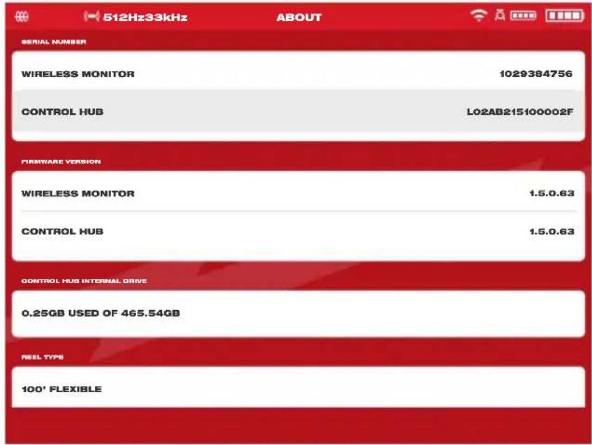
3. M18™ 500GB Control Hub
3.1 Overview
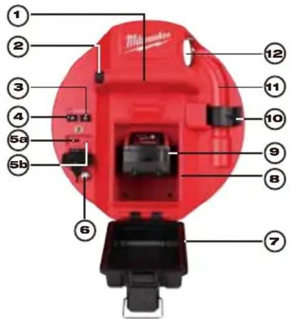
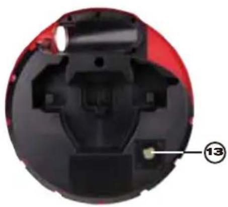
natural_image
Cross-sectional view of a mechanical device with red and black components, labeled with number 13 (no text or symbols beyond label)| Reference | Description |
| 1. Handle | |
| 2. | Control Hub lock release button – push to unlock the Control Hub assembly from the Pipeline Inspection Reels |
| 3. Power button – Press to turn on, press and hold to turn off | |
| 4. Distance reset button – resets the distance of deployed push cable to Zero | |
| 5. | USB compartment cover – is a watertight cover to keep debris out of the compartment.5a USB-A port – for direct saving of videos and pictures and to perform firmware updates.5b USB-C port – optional for supplying power and data between the Wireless Monitor and Control Hub. |
| 6. | Grounding post – to ground the Control Hub to earth while tracing push cable |
| 7. | Batterycompartmentcover–isawatertightcovertokeepdebrisoutofthe compartment. |
| 8. Battery compartment – for M18TM Battery | |
| 9. M18TM Battery | |
| 10. | Spring locking clip – holds the spring and camera in place during transportation |
| 11. | Spring recess – keeps the spring and camera in place during transportation and storage. |
| 12. | Cable guide – feed the spring and push cable through the guide before locking the Control Hub in place |
| 13. | Camera test port – is a troubleshooting tool for isolating the camera head's performance |
3.2 Installing and removing the M18™ 500GB Control Hub
Installing the M18™ 500GB Control Hub
- Grasp the Control Hub by the handle and present it to the Pipeline Inspection Reel.
- On the back of the reel, turn the push cable drum brake locking knob counterclockwise to unlock it.
- Reach into the reel and grab the spring termination assembly.
- Feed the spring and one foot of push cable through the cable guide.
- Push the Control Hub into the Pipeline Inspection Reel until the locking click sound is heard.
- Push the push cable and spring termination back into the Pipeline Inspection Reel until the spring lines up with the spring holder.
- Push the spring into the spring locking clip.
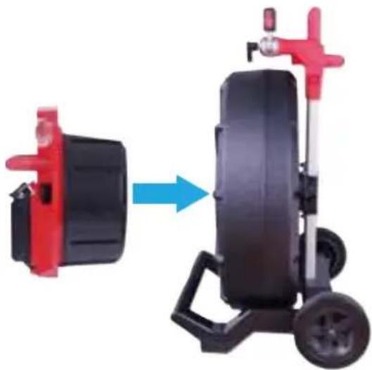
natural_image
Mechanical device with red and black components, showing a blue arrow pointing to a black cylindrical component (no text or symbols visible)Service Note – Dielectric grease is applied between the Hub-to-Reel connections in the Hub before the unit is shipped. Over time it may be necessary to re-apply this grease especially if you suspect any Hub-to-Reel connectivity issues or image quality issues.
Use Milwaukee type X Dielectric Grease (Part#: 49-08-5000) or equivalent to apply beads of grease to the Hub terminals as shown below. After adding the grease insert and remove the Hub a few times to adequately coat the terminals.

natural_image
Close-up of a hand inserting a plastic clip into a black plastic container (no visible text or symbols)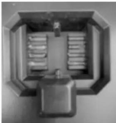
natural_image
Top-down view of a mechanical or electrical enclosure with internal compartments and a central control unit (no visible text or symbols)Apply dielectric grease to the Hub terminals
Removing the M18™ 500GB Control Hub
- On the back of the reel, turn the push cable drum brake locking knob counterclockwise to unlock.
- Remove the spring from the spring holder.
- Push the push cable and spring into the push cable drum.
- Press the unlock button and remove.
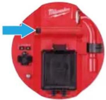
natural_image
Red industrial machine component with blue arrow pointing to a component (no visible text or symbols)3.3 Using the M18 ^TM 500GB Control Hub
⚠WARNING Recharge only with the charger specified for the battery. For specific charging instructions, read the operator's manual supplied with your charger and battery.
3.3.1 Power on/off
Press the Power ① button on the M18™ 500GB Control Hub. The buttons on the Control Hub will illuminate, showing that the power is on. The Control Hub symbol will appear in the status bar of the M18™ Wireless Monitor along with the Control Hub's battery state.
3.3.2 USB Ports
| Port Type Illustration Purpose | ||
| USB-A Port | 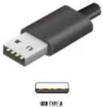 | The USB-A port is the day to day use port. It allows for direct recording of video and picture files or transferring files from the M18TM 500GB Control Hub Internal Drive.This drive is also used to perform firmware updates to Control Hub. |
| USB-C Port | 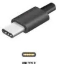 | The USB-C port is used for:Connecting the M18TM Wireless Monitor to the M18TM 500GB Control Hub bypassing a Wi-Fi connection.Power the M18TM 500GB Control Hub from the M18TM Wireless Monitor when no battery is present in the Hub or vice versa. |
3.3.3 Grounding Post
The grounding post must be used while using the Line Trace feature to trace push cable. The M18™ 500GB Control Hub must be grounded to close the current loop to send out a good locate signal. Use the supplied grounding cable assembly with ground stake to ground the Control Hub to earth.

3.3.4 Distance Counter Reset
As the Pipeline Inspection Reel rotates, the distance of push cable deployed is shown on the status bar of the Wireless Monitor in Feet and inches or Meters and Centimeters. When pulling back the push cable if the counter passes "0" it will begin to count in negative footage. For example -1'0" or -2'3". There are two methods to reset the distance count.
Press the Distance Reset 📄 button on the M18™ 500GB Control Hub or M18™ Wireless Monitor and the distance shown in the Wireless Monitor will reset to "0".
3.3.5 Camera Test Port
As a troubleshooting tool, on the rear of the M18™ 500GB Control Hub, a Camera Test Port is available. If ever any camera head problems occur, the user can isolate the camera head from the rest of the system for troubleshooting.
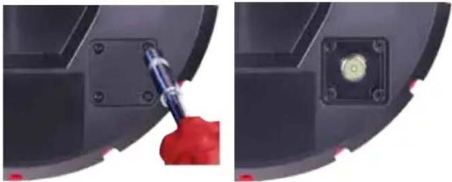
natural_image
Close-up of a mechanical component with a red-handled tool applying material to a yellow circular component (no text or symbols visible)Remove the four combination head screws to access the camera test port
- With the Control Hub powered off, remove it from the reel.
- On the rear of the Control Hub, remove the four combination head screws from the camera test port cover.
- Screw the camera head onto the male threads of the test port. Hand tighten only.
- Power on the Control Hub.
- Power on the M18™ Wireless Monitor or tablet running the Milwaukee ^® Pipeline Inspection App, and connect to the Control Hub checking for picture and control of the cameras LED's.
3.4 Formatting the M18™ Control Hub Internal and Thumb Drives
This setting allows the formatting of the M18™ 500GB Control Hub's Internal 500GB Drive or a USB thumb drive. The system requires that USB thumb drives be formatted in NTFS or FAT32 file system in a computer running a Microsoft Windows operating system. Any new thumb drives should already be formatted in NTFS or FAT32 but if the Control Hub does not recognize the USB Thumb Drive follow the below instructions making sure to select Control Hub Thumb Drive. Alternatively, a USB thumb drive can be formatted in a Windows desktop PC or laptop. See the end of this section on instructions on how to do this.
Formatting the M18™ Control Hub or Thumb Drives
- Turn the navigation dial to Settings ☐, press the navigation dial.
- Turn the navigation dial to Format Disk, press the navigation dial to enter the submenu.
Select the Control Hub Internal Drive (Hub SSD) or the Control Hub Thumb Drive (Hub USB) and press the navigation dial.
3 M18 ^TM 500GB Control Hub
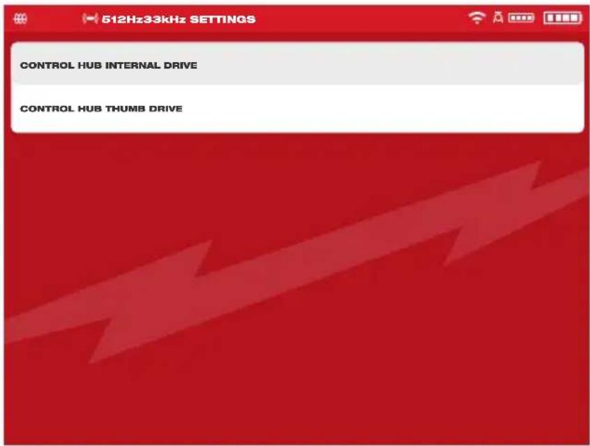
- Press the navigation dial and accept the on-screen message to continue.
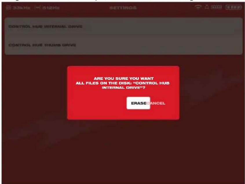
- The selected drive will be formatted, and the system will return to the Settings menu.
- Press the Back ← key to return to the main viewing screen.
Formatting USB thumb drives in a Windows desktop PC or laptop
- Insert the USB thumb drive into the PC or laptop.
- Right mouse click on the USB thumb drive and select Format.
- Select FAT32 or NTFS under File System.
- Click Start. Acknowledge the warning message by clicking OK.
- The file format procedure will run and when finished the Format Complete message will appear.
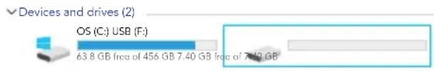
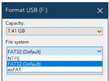
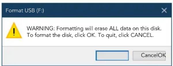
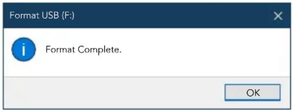
3.5 Factory Reset & System Update – M18 ^TM 500GB Control Hub
These two tasks can be accomplished by using the M18 ^™ 500GB Control Hub and M18 ^™ Wireless Monitor or a tablet running the Milwaukee ^® Pipeline Inspection App.
3.5.1 Factory Reset - M18™ 500GB Control Hub
Performing a factory reset will reset the M18 ^™ 500GB Control Hub to the factory defaults. In the Control Hub, the functionality that will reset to the factory default will be:
- Labels will be erased
• Video and Image settings back to default :1080p
• The Company Name is removed - Sonde frequency back to default
• Line Trace back to default - Screen Settings back to default: Hue, Brightness, Contrast, Saturation.
-
Units of measure
-
On the M18™ Wireless Monitor, turn the navigation dial to Settings ☐, press the navigation dial. Turn the navigation dial to Factory Reset, press the navigation dial to enter the sub-menu.
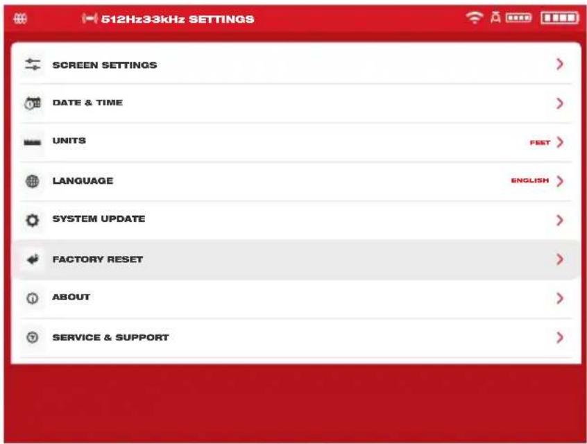
- Select Factory Reset Control Hub and press the navigation dial.
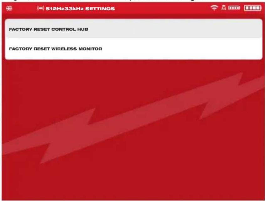
- Read and acknowledge the Reset message by selecting OK.

The factory reset is now complete, and the system is returned to the Factory Reset sub-menu.
3.5.2 System Update - M18™ 500GB Control Hub
Firmware updates are periodically released to introduce new features and optimizations. Before updating a system, go to the About section of the Settings menu and make a note of the current firmware revisions in the system.
Firmware updates can be performed with the M18 ^™ Wireless Monitor or tablet running the Milwaukee ^® Pipeline Inspection App.
Firmware updates are found at www.milwaukeetool.com.
- Go to the Milwaukee® website and click the SUPPORT link, then click on MANUALS AND DOWNLOADS.
- Enter the CATALOG NUMBER, which can be found on the front cover of this manual, in the search box.
- Select SOFTWARE DOWNLOAD and then click on GO.
- Drag the downloaded firmware update file onto a USB thumb drive or right mouse click and select copy, then paste the firmware update file to a USB thumb drive.
- Turn on both the M18 ^™ 500GB Control Hub and M18 ^™ Wireless Monitor or tablet running the Milwaukee ^® Pipeline Inspection App.
- Check that the Wireless Monitor or tablet running the Milwaukee® Pipeline Inspection App is connected to the Control Hub by Wi-Fi. If it is not connected, you will need to connect it.
- Insert the USB thumb drive containing the firmware update into the Control Hub's USB-A port.
- Turn the navigation dial to Settings, press the navigation dial.
- Turn the navigation dial to System Update, press the navigation dial to enter the submenu.
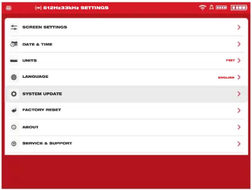
- Select Control Hub and press the navigation dial. The filename of the update should be seen in this window. Press the navigation dial to begin the update.
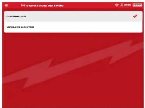
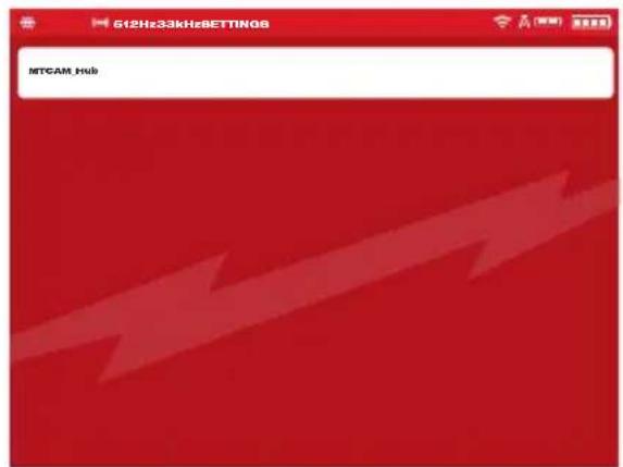
Select Control Hub The firmware update is shown
- Read and acknowledge the warning message by selecting OK.
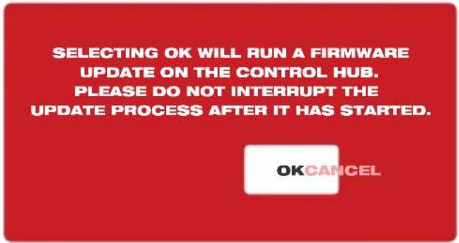
- A progress indicator will appear showing the progress of the update.

- A confirmation message will appear when the update is complete. Select OK to reboot the system.

- Go to the About option in the Settings menu to check that the firmware revision numbers have been updated.
3.5.3 M18 ^TM 500GB Control Hub System Update - Over the Air
This section covers updating the M18 ^™ 500GB Control Hub using the Pipeline Inspection App. This is an over-the-air firmware update and does not require using a USB thumb drive.
If an M18 ^™ Wireless Monitor is connected to the hub when an over-the-air update is run both the hub and monitor will be updated if needed.
Firmware updates are periodically released to introduce new features and optimizations. Before updating a system, go to the About section of the Settings menu and make a note of the current firmware revisions in the system.
When new firmware is released it is automatically added to the App. When the App connects to the hub it compares its firmware version to the latest and will ask to be installed.
- After the connection to the hub has been established the update message will appear. Click Install to start the installation process.

- Confirm the installation after reading the important message by clicking on Install.
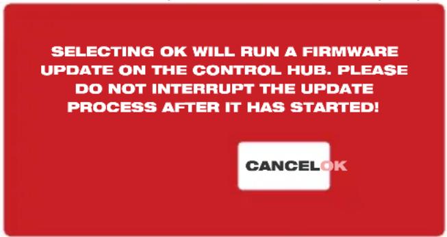
- After the hub has been updated, the update confirmation message will appear and the hub will reboot. The firmware update has been successful.

4. Pipeline Inspection Reel
4.1 200' Mid-Stiff, 200' and 325' x Stiff Pipeline Inspection Reel Overview
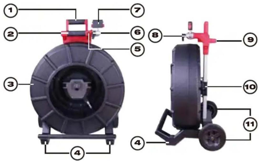
| Reference | Description |
| 1. Retractable handle (shown in the lowered position) | |
| 2. Retractable handle lock and release button | |
| 3. Push | cable drum and push cable |
| 4. Vertical position feet | |
| 5. Wireless Monitor rotation lock | |
| 6. Tilt lock | |
| 7. Wireless Monitor mount/Tablet Mount connector | |
| 8. Wireless Monitor mount swivel | |
| 9. Horizontal position feet | |
| 10. Push | cable drum brake |
| 11. Wheels | |
4.2 120' Mid-Stiff Pipeline Inspection Reel Overview
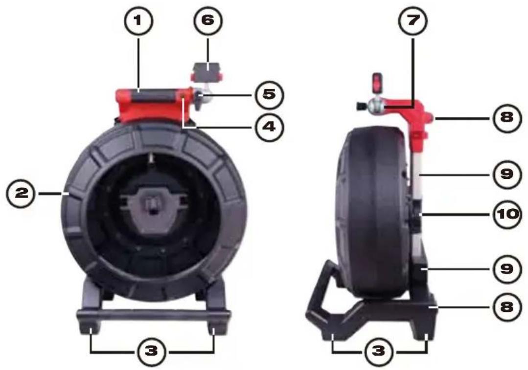
| Reference | Description |
| 1. | Handle |
| 2. | Push cable drum and push cable |
| 3. | Vertical position feet |
| 4. | Wireless Monitor rotation lock |
| 5. | Wireless Monitor tilt lock |
| 6. | Wireless Monitor/Tablet Mount connector |
| 7. | Wireless Monitor mount swivel |
| 8. | Horizontal position feet |
| 9. | Backpack mounts |
| 10. | Push cable drum brake |
4.3 100' Flexible Pipeline Inspection Reel Overview
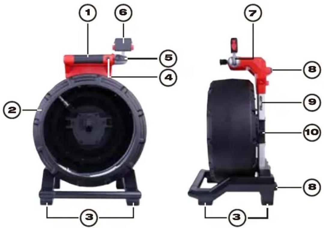
| Reference | Description |
| 1. Handle | |
| 2. Push | cable drum and push cable |
| 3. Vertical position feet | |
| 4. Wireless Monitor rotation lock | |
| 5. Wireless Monitor tilt lock | |
| 6. Wireless Monitor/Tablet Mount connector | |
| 7. Wireless Monitor mount swivel | |
| 8. Horizontal position feet | |
| 9. Carry | strap mounting rings |
| 10. Push | cable drum brake |
4.4 Installing the Backpack Plate – 100' Flexible and 120' Mid-Stiff Pipeline Inspection Reel
The 100' Flexible and 120' Mid-Stiff Pipeline Inspection Reel comes with a backpack mounting plate which allows the reel to be carried as a backpack. This is useful for transporting the small reel to and from the job site. This is extremely helpful for climbing stairs or ladders.
NOTICE Use care when transporting this tool when the reel and backpack are connected. Tipping may occur.

natural_image
Back view of a black and red athletic backpack with attached-mounted sensor (no text or symbols visible)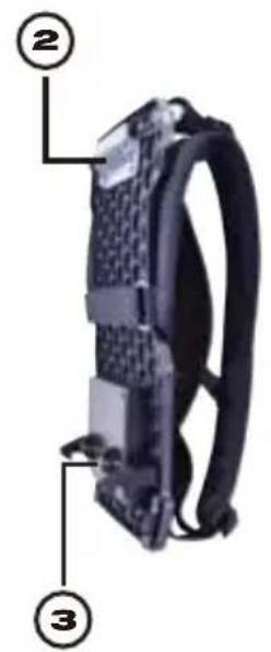
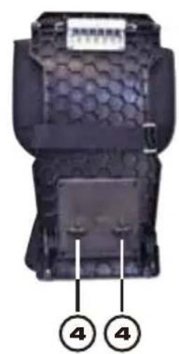
| The rear of 120' Pipeline Inspection with backpack plate installed | Backpack plate side view | Backpack plate rear view |
| 1. Release lever 2. Top mounting | ting plate3. Bottom retaining hooks | 4. Male mounting post |
| Removing the backpack plate | |
| 1. Lift the release lever to unlock the backpack plate. |  |
| 2. Pull the bottom of the backpack plate away from the reel and downward in one motion. |  |
| Installing the backpack plate | |
| 1. Push the top mounting plate into the reels top mounting receptacle. |  |
| 2. Now push the bottom of the backpack into the reel lining up the male mounting post. |  |
| 3. Push with the palm against the bottom of the backpack until it locks in place. Give a slight tug to make sure that it is locked in place. | |
4.5 Installing the Shoulder Strap – 100' Flexible Pipeline Inspection Reel
The 100' flexible pipe inspection reel is equipped with a shoulder strap that allows the reel to be carried over the shoulder like a shoulder bag.
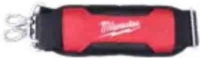
natural_image
Red and black fitness tracker with scissors, no visible text or symbolsShoulder Strap
NOTICE When using a shoulder strap to transport the reel, ensure that the clips on both sides have been fixed on the lifting lugs.
| Installing the shoulder strap | |
| 1. Find two stainless steel lifting lugs on the back of the reel. | 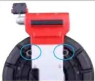 |
| 2. Hold the lock catch at both ends of the shoulder strap, and press the lock catch firmly until the lock catch on the stainless steel lifting lugs. |  |
| 3. After installing the lock catch on both sides, check the lock catch and pull the shoulder belt to ensure that the lock catch is firmly clamped on the lifting lug. |  |
| Removing the shoulder strap | |
| 1. Hold the lock catch on the lifting lugs on both sides, and press the lock catch down firmly to separate it from the lifting lugs. | 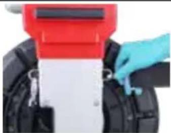 |
| 2. Now the lock catch has been removed from the reel. |  |
4.6 Mounting the M18 ^TM Wireless Monitor
The M18™ Wireless Monitor or Tablet Mount can be mounted on both the mini and standard size Pipeline Inspection Reels. Once mounted, the monitor or tablet can be adjusted for the best viewing angle in both vertical and horizontal positions.
WARNING
To reduce the risk of short circuit, when setting tool or battery down, battery to contact corrosive or conductive fluid.
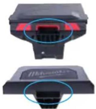 | 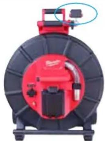 |
| Mount receptacle on the bottom of Wireless Monitor and Tablet Mount | Wireless Monitor and Tablet Mount on Pipeline Inspection Reel |
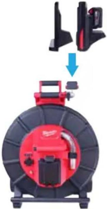 | 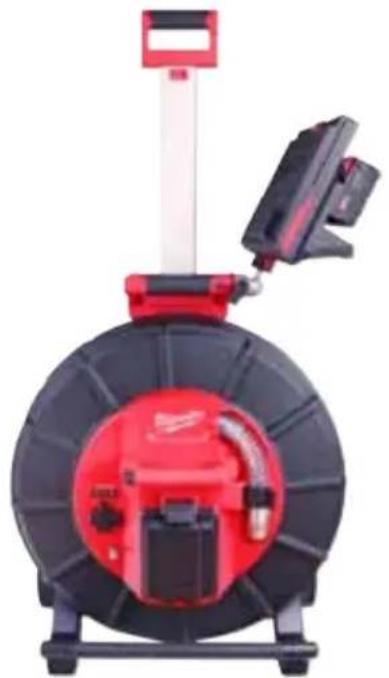 |
| 1. Line up the Wireless Monitor or Tablet Mount mounting receptacle with the mounting block on the Pipeline Inspection Reel. | 2. Lower in place and press until the locking click is heard. |
Adjust the viewing angle of the Wireless Monitor:
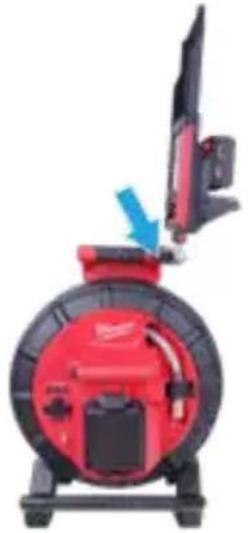 |  |
| 1. Loosen the adjustment arm by turning the arm clockwise. | 2. Move the Wireless Monitor to the desired angle.3. Tighten the adjustment arm counterclockwise until tight. |
Adjust the tilt angle of the Wireless Monitor:
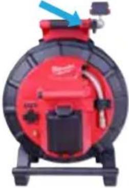 |  |  |
| 1. Press the locking tilt button to unlock the adjustment block. | 2. Turn the mounting block towards the opening of the drum until it locks in place. | 3. Adjusting the tilt angle is useful when using the reel in the horizontal position. |
4.7 Using the Pipeline Inspection Reel
⚠ WARNING Use latex or rubber gloves, goggles, face shields, protective clothing, and respirator when chemicals, bacteria or other toxic or infectious substances are suspected to be in a drain line. Drains may contain chemicals, bacteria and other substances that may cause burns, be toxic or infectious or may result in other serious personal injury.
⚠ WARNING To reduce the risk of explosion, electric shock and property damage, always check the work area before beginning a job. Do not allow cable to contact electrical, chemical, or moving hazards.
Do not use the push cable to clear clogs or move obstructions. This is not a drain cleaner!
4 Pipeline Inspection Reel
- Position the reel on a flat surface approximately three to six feet or one to two meters from the entry point. This will provide enough space to work with the push cable without a lot of slack dragging on the ground. Use the friction brake to slow down the movement of the push cable drum if needed.
Using the reel in a horizontal position makes the width between the feet greater. This will give the reel more stability if on uneven surfaces and will lower the height when in confined spaces.
- Unlock the spring then loosen the friction brake so that the push cable drum can spin.
- The push cable is now ready to be deployed into the pipe.
4.8 Push Cable
Check Push Cable for Wear - Visually inspect the push cable for cuts, kinks, and abrasions as it is retrieved back into the cable cage. If the jacket is cut or worn to the point that the yellow or white Kevlar braid can be seen, then it is time to replace the push cable. Using the push cable with open cuts will result in water and moisture entering the push cable and eventually traveling through it, causing a degraded camera image, or total image failure.
The push cable sections shown below are examples of badly worn jackets. Push cable such as this should be replaced as soon as possible.
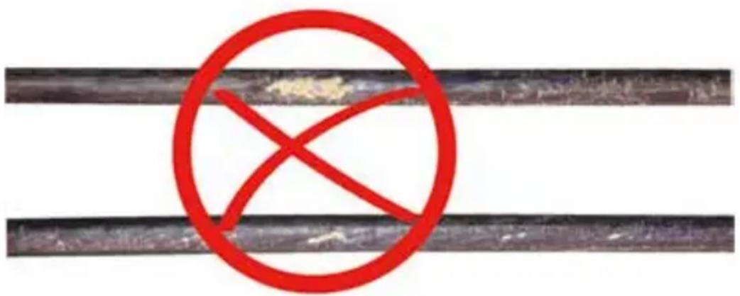
natural_image
Red circular symbol with 'X' crossed out of a black horizontal line, indicating no crossing or rejection (no text or numbers present)⚠WARNING To reduce the risk of fire, personal injury, and product damage, never immerse your tool, battery pack or charger in fluid or allow a fluid to flow inside them. Always remove battery pack before cleaning.
Keep the Push cable and Termination Spring Assembly dry and clean – When retrieving the push cable keep a clean, dry rag in one hand and wipe down the push cable as it moves through it. At the end of the day, use low-pressure water to rinse off the camera head and rinse away accumulated dirt and debris that may be caught in the spring. Shake dry or use low-pressure air to blow the excess water away and dry off the parts. The Camera Head, Push Cable and Termination Parts are exposed to very harsh chemicals in day-to-day use. Keeping a clean system will help prolong the life of these parts.
Maintain proper control of the push cable – Attempting to pull the push cable out of the reel while the reel is locked will result in the push cable collapsing in the reel and stressing the push cable. Pushing the push cable back into the reel while it is locked may cause the reel to tip over or kink the cable.
5. Camera Heads and Spring Assembly
5.1 Camera Heads
The 200' and 325' Stiff Pipeline Inspection Reels come with a 34mm self-leveling camera head. The 100' Flexible, 120' Mid-Stiff and 200' Mid-Stiff Pipeline Inspection Reels come with a 25mm diameter self-leveling camera head. A custom camera wrench is provided for their removal and installation. The 120' and 200' Mid-Stiff, 200' and 325' Stiff Pipeline Inspection Reels camera heads are provided with a plastic protective cover. Always use the protective cover while using the Pipeline Inspection Reel.
| Face: 34mm 25mm | ||
 |  | 1. Polycarbonate LED cover2. Sapphire glass lens |
| Body: 34mm 25mm | ||
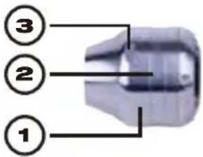 | 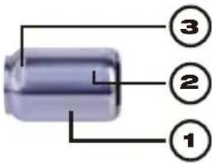 | 1. Main Housing2. Serial number location3. Wrench Flats |
| Rear: 34mm 25mm | ||
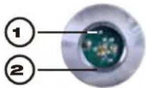 | 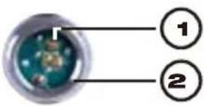 | 1. Connecting contact pins2. Internal base threads |
A custom camera wrench is supplied with the Pipeline Inspection Reel. Use the wrench to tighten and remove the spring assembly and camera head.

natural_image
Pure mechanical wrench symbol without any text or labelsNOTICE Do not overtighten or use excessive force!
Custom Camera Wrench
5.2 Parts of the Spring Assembly
The spring assembly is comprised of the parts that connect the camera head on one end to the push cable on the other. The reel end of the assembly has wrench flats for removal and installation.
The spring termination assembly consists of an all-in-one spring, coiled cable assembly, and steel lanyard.
| Spring Assemblies | ||
Reel End | 100' Flexible Pipeline Inspection Reel Spring Assembly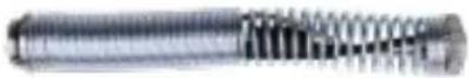 | Camera End |
Reel End | 120'/200' Mid-Stiff Pipeline Inspection Reel Spring Assembly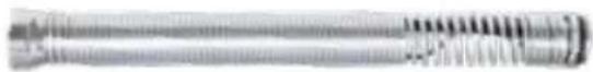 | Camera End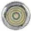 |
Reel End | 200'/325' Stiff Pipeline Inspection Reel Spring Assembly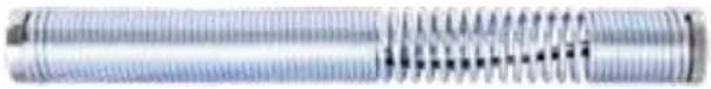 | Camera End |
5.3 Removing and Installing the Camera Heads
NOTICE Avoid touching the green circuit board or gold pins on the spring assembly or camera head with bare hands. Touching these will transfer oils from the fingers to these components, which may lead to premature corrosion. Wear clean, dry rubber gloves if possible.
5.3.1 Camera Head Removal
| Before removing the camera head, wipe it dry, and remove any dirt that may fall into the camera connection areas. | |
| 1. Grasp the spring assembly close to the base of the camera head. |  |
| 2. Use the camera wrench to loosen the camera head by turning in a counterclockwise direction. |  |
| 3. After the camera head is loose, continue to unscrew the camera until removed. |  |
| Place the camera head in an area where the contact pins will not be damaged. | |
5.3.2 Camera Head Installation
| 1. Grasp the spring assembly close to the camera head end of the spring assembly. |  |
| 2. Slowly screw on the camera head in a clockwise direction, being careful not to cross thread the connections. |  |
| 3. Use the supplied wrench to tighten the camera head.NOTICE Do not overtighten or use excessive force! |  |
5.4 Removing and Installing the Spring Assembly
NOTICE Avoid touching the green circuit board or gold pins of the spring assembly or camera head with bare hands. Touching these will transfer oils from the fingers to these components, which may lead to premature corrosion. Wear clean rubber gloves if possible.
5.4.1 Spring Assembly Removal
| Before removing the spring assembly, wipe it dry and remove any dirt that may fall into either end of the spring's connections. | |
| Remove the camera head following the instructions shown in 5.3.1 | |
| 1. Grasp the sonde compartment at the base of the termination area where it connects to the push cable. | 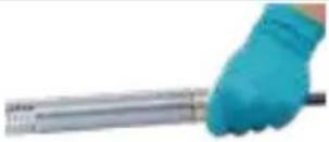 |
| 2. With the other hand, use the supplied wrench to loosen the spring assembly. | 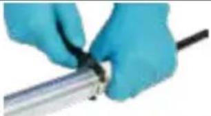 |
| 3. After the spring assembly is loose, continue to unscrew counterclockwise until removed. |  |
| Place the spring assembly in an area where the contact pins will not be harmed. | |
5.4.2 Spring Assembly Installation
| 1. Grasp the sonde compartment at the base of the termination area where it connects to the push cable. |  |
| 2. Slowly screw the spring assembly on in a clockwise direction being careful not to cross thread the connections. |  |
| 3. Use the supplied wrench to tighten. |  |
| 4. The spring assembly is installed correctly when the Black O-Ring at the base of the sonde compartment is no longer visible.NOTICE Do not overtighten or use excessive force! |  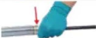 |
5.5 Camera Skids and Protective Covers
Protective Covers – are covers that fit over the 25mm and 34mm camera heads. The protective covers are provided with all Pipeline Inspection Reel systems or replacement camera heads.
Skids – are devices that attach to the spring assembly to keep the camera head off the floor of the pipe and prevent the camera head from making direct contact with the pipe.
5.5.1 The Protective Covers
| 25mm and 34mm camera heads | |||
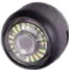 | 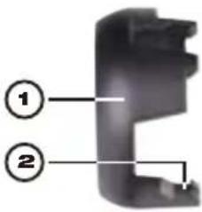 | 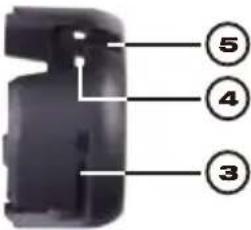 | 1. Top half, (front)2. Locking tab3. Wrench flats4. Tab receptacle5. Screwdriver slot |
5.5.2 Removing the Protective Covers
| 1. Insert a flat screwdriver into the slot and lift until the locking tab releases. |  |
| 2. Place your thumb against the locking tab to prevent it from falling back into place while moving to the next tab to unlock it. |  |
| 3. Remove the top portion of the protective cover. |  |
5.5.3 Installing the Protective Covers
| 1. Place the rear half of the protective cover on the back of the camera head. |  |
| 2. Twist the camera while pressing down so the cameras wrench flats line up and lock into the cover. | |
| 3. Line up the protective cover locking tabs and press the top half into the bottom half. Press until all the locking tabs have snapped into place, locking the cover in place. |  |
5.5.4 Camera Skids
The below skid types available for the 25mm and 34mm camera heads.
| 100' Flexible Reel | Mid-Stiff and Stiff Reel Skids | |||
| 25mm Barrel Skids | 25mm Barrel Skids | 34mm Barrel Skids | 25mm Star Skids* | 34mm Star Skids* |
 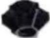 |   |  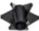 |   |  |
| 2" and 2-1⁄2" | 2-1⁄2" and 4" | 3" and 4" | 2-1⁄2" and 4" | 3" and 6" |
| * The 4" star skid can be trimmed to 3.5" or 3"* The 6" star skid can be trimmed to 5" or 4" | ||||
5.5.5 Adjusting the Star Skid
The fins of the star skid contain raised fin length indicators. Use these indicators to trim the length of fins so it can fit into a smaller diameter pipe.
The fin lengths of the star skid is 6-inches. Using the length indicators as a guide the skid can be trimmed to 5-inches or 4-inches in diameter.
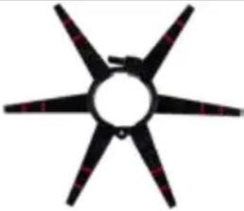 Trim Indicators Trim Indicators | |||
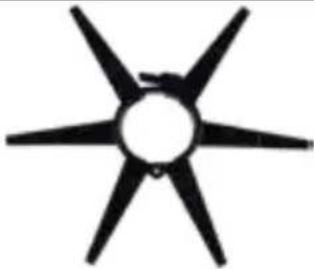 6-inch Star Trim to 6-inch Star Trim to | 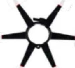 5-inches Trim to 4-inches 5-inches Trim to 4-inches | 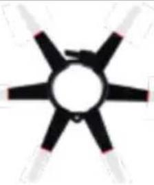 | |
5.5.6 Installing the Barrel Skid
| 1. Fully open the camera skid, place the spring into the skid.Position the skid so that the camera is level. |  |
| 2. Close the camera skid and pinch the fins together while pushing the screw into the hole. |  |
| 3. Screw until tightened.NOTICE Do not overtighten or use excessive force! | 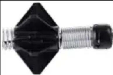 |
5.5.7 Installing the Barrel Skid with 100' Flexible Pipeline Inspection Reel Spring Only
| 1. Fully open the barrel skid, place the spring into the skid. | 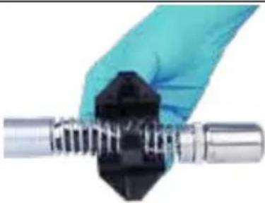 |
| 2. Close the barrel skid and pinch the ends together while listening for the locking clicking sound. | 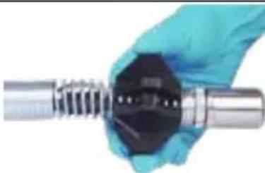 |
5.5.8 Installing and Removing the Star Skid
The Star skid can be used in various configurations, alone or combined with the barrel skid.
Installation
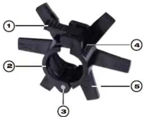 | 1. Release lever2. Retention rib3. Hinge4. Catch plate5. Skid fins |
| 1. Fully open the star skid, place the spring into the skid. | 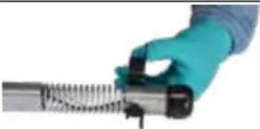 |
| 2. Close the star skid and pinch the ends together while listening for the locking clicking sound. | 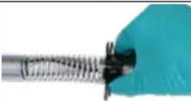 |
Removal
| 1. Place the spring on a flat surface and use the thumb to firmly press down on the release lever. | 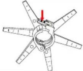 |
| 2. While pressing the release lever push the release lever forward and the skid will open. | 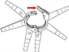 |
| Alternate skid configurations | |
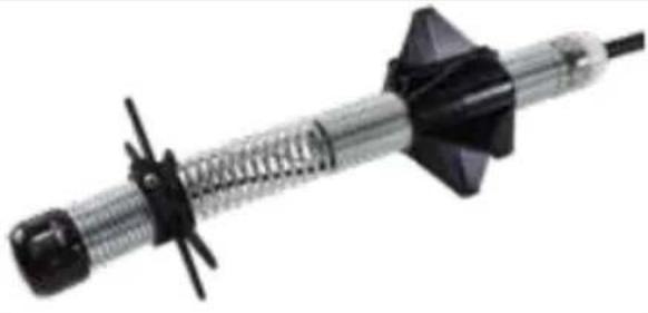 | 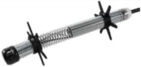 |
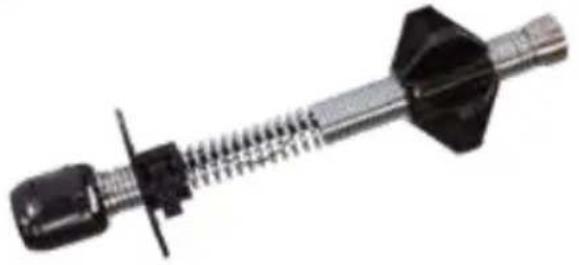 | 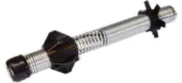 |
6. Service & Support
If any part of your Pipeline Inspection System should require service, you will find Milwaukee Tool's service page and support number in the Service & Support directory.
- Turn the navigation dial to Settings ☐, press the navigation dial.
- Turn the navigation dial to Service & Support, press the navigation dial to enter the directory.
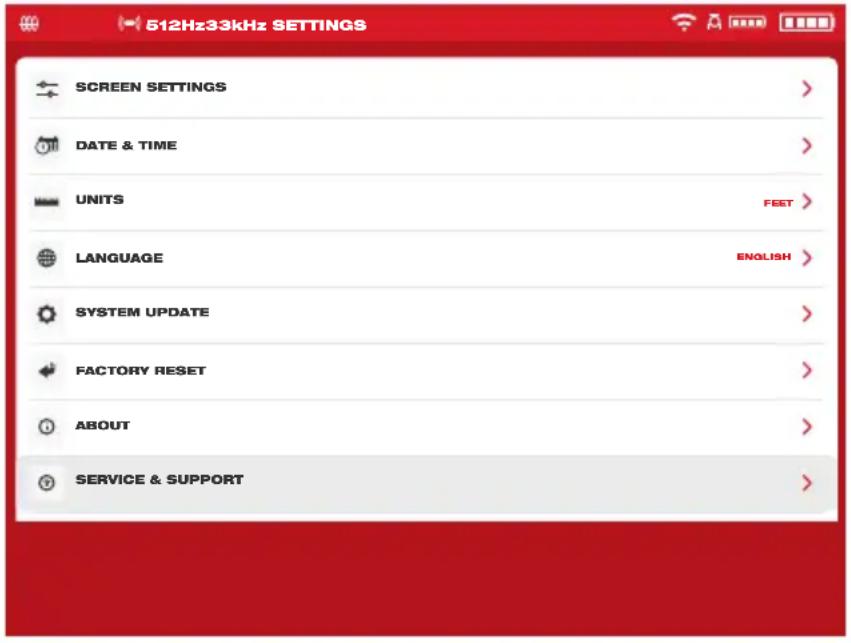
Federal Communications Commission (FCC)

Milwaukee Tool (Canada) Ltd
1.800.268.4015
natural_image
Close-up of a mechanical device with black and red components, no visible text or symbols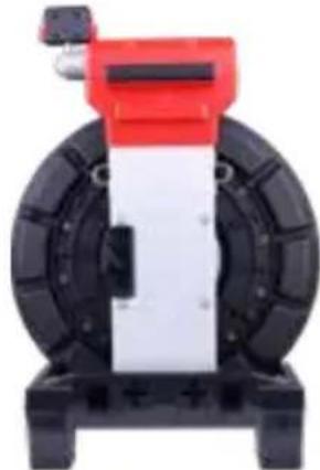
natural_image
Mechanical device with red and black components, no visible text or symbolsnatural_image
Close-up of a black tire device with red handle and mounting base (no visible text or symbols)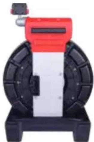
natural_image
Exterior view of a mechanical device with red top and black base (no visible text or symbols)natural_image
Top-down view of a black industrial machine with red top and black body (no visible text or symbols)natural_image
Top-down view of a red and black industrial machine with wheels and central panel (no visible text or symbols)natural_image
Top-down view of a black industrial tire with red handle and mounting base (no visible text or symbols)natural_image
Top-down view of a black and white wheeled machine with red top handle (no visible text or symbols)natural_image
Top-down view of a black industrial fan or motor with red clamps and a central hub (no visible text or symbols)natural_image
Top-down view of a mechanical device with black wheels and a red top component (no visible text or symbols)natural_image
Grayscale aerial or satellite view of a coastal area with visible water and debris, captured in a mobile camera interface (no readable text or symbols)natural_image
Close-up grayscale image of a human eye with visible corneal reflection (no text or symbols)Submenu de galerie
natural_image
Cross-sectional view of a mechanical device with red and black components, labeled with number 13 (no text or symbols beyond label)natural_image
Two mechanical devices, one black and one red, with a blue arrow pointing to a larger black cylindrical device (no text or symbols visible)natural_image
Close-up of a hand inserting a plastic bottle into a black plastic container (no visible text or symbols)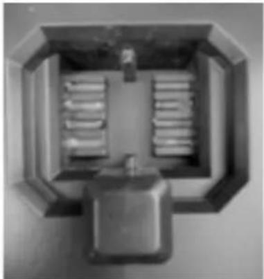
natural_image
Top-down view of a mechanical or electrical component with internal channels and a central housing (no visible text or symbols)natural_image
Red circular device with black components and a blue arrow pointing to a component (no visible text or symbols)natural_image
Close-up of a hand using a screwdriver to adjust or install a small electronic component, showing no text or symbols.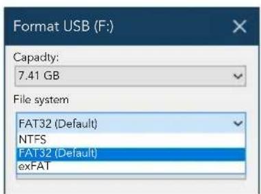
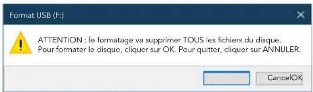
natural_image
Back view of a black and red athletic equipment device (no visible text or symbols)1
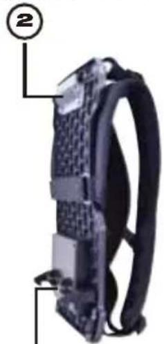
natural_image
Close-up of a black electronic device with attached cable and connector (no visible text or symbols)③
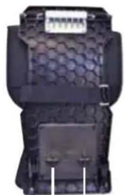
natural_image
Close-up of a black plastic container with hexagonal pattern and side slots (no visible text or symbols)4 4
natural_image
Red and black fitness tracker with scissors, no visible text or symbolsBandoulière
natural_image
Pure black mechanical wrench symbol without any text or labelsnatural_image
Symmetrical black starburst pattern with red markings, no text or symbols presentnatural_image
Abstract black starburst shape with a central circle and eight radiating arms (no text or symbols)natural_image
Abstract black starburst shape on white background (no text or symbols)natural_image
Abstract black star-like geometric shape with a central circle and radiating lines (no text or symbols)Milwaukee Tool (Canada) Ltd
1.800.268.4015
Lunes a viernes, de 7:00 AM a 4:30 PM CST
o visite www.milwaukeetool.ca
natural_image
Close-up of a mechanical device with black and red casing, no visible text or symbols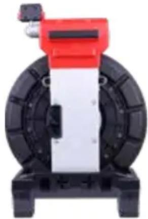
natural_image
Mechanical device with red and black components, no visible text or symbolsVista delantera Vista trasera
1 Presentación
natural_image
Close-up of a black tire with red and black components, no visible text or symbolsVista delantera Vista trasera
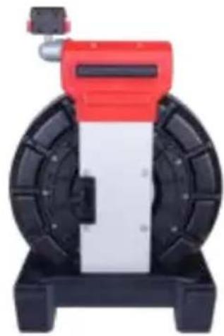
natural_image
Exterior view of a mechanical device with red top and black base (no visible text or symbols)natural_image
Top-down view of a black industrial fan or pump unit with red mounting bracket (no visible text or symbols)Vista delantera Vista trasera

natural_image
Top-down view of a red and black industrial machine with wheels and central panel (no visible text or symbols)natural_image
Top-down view of a black industrial fan or pump device with red handle and mounting base (no visible text or symbols)Vista delantera Vista trasera

natural_image
Top-down view of a black and white cylindrical mechanical device with red top and control panel (no visible text or symbols)1 Presentación
natural_image
Top-down view of a black industrial fan or motor housing with red clamps and a central hub (no visible text or symbols)Vista delantera Vista trasera
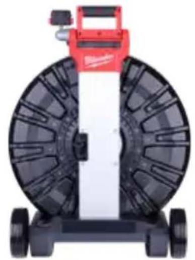
natural_image
Top-down view of a mechanical device with black wheels and a red top component (no visible text or symbols)2. Monitor inalámbrico M18™
natural_image
Interior view of a tunnel or tunnel entrance with visible water and a central circular object, captured in a video player interface (no readable text or symbols on the main subject)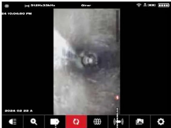
natural_image
Grayscale aerial or satellite view of a vehicle with visible sensor or camera, captured in a mobile interface (no readable text or symbols)natural_image
Close-up of a dark, circular object with a bright center and diffuse surrounding surface (no visible text or symbols)natural_image
Blurred grayscale image of an indistinct object with no visible text or symbols, possibly a dark circular object (no readable text or symbols)natural_image
Black-and-white image of a film clapperboard icon on a dark textured background, with no visible text or symbols.natural_image
Interior view of a tunnel with a central circular structure and surrounding vegetation (no visible text or symbols)Submenú de Galería
natural_image
Cross-sectional view of a red and black mechanical device with internal components (no visible text or symbols)natural_image
Two mechanical devices, one red and one black, with a blue arrow pointing to the next device (no text or symbols visible)natural_image
Close-up of a hand inserting a plastic bottle into a black plastic container (no visible text or symbols)
natural_image
Top-down view of a mechanical or electrical component with internal channels and a central housing (no visible text or symbols)natural_image
Red circular electronic device with black components and a blue arrow pointing to a component (no visible text or symbols)natural_image
Black mechanical component with articulated arms and a handle (no visible text or symbols)natural_image
Illustration of a red industrial machine with a digital display and cable, connected to a ground surface (no text or symbols)natural_image
Close-up of a mechanical component with a red-handled tool inserted, showing a close-up view (no text or symbols visible)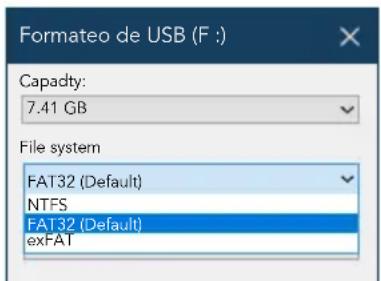
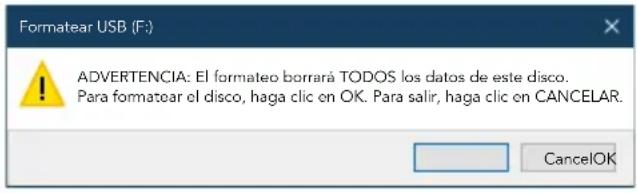
natural_image
Back view of a black athletic backpack with red accents and a numbered label (1) pointing to the side, no visible text or symbols on the backpack itself.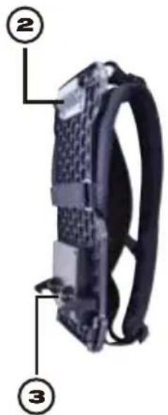
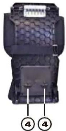
natural_image
Close-up of a black plastic enclosure with hexagonal pattern and two labeled parts (4), no readable text or symbols beyond labels.natural_image
Close-up of a black and red fitness tracker with scissors, no visible text or symbolsCorrea de hombros
natural_image
Pure electrical circuit lines without any symbols13135 West Lisbon Road
Brookfield, WI 53005 USA

- GENERAL POWER TOOL SAFETY WARNINGS
- ⚠ WARNING
- WORK SAFETY AREA
- ELECTRICAL SAFETY
- PERSONAL SAFETY
- POWER TOOL USE AND CARE
- BATTERY TOOL USE AND CARE
- SERVICE
- SPECIFIC SAFETY RULES FOR PIPELINE INSPECTION SYSTEMS
- FEDERAL COMMUNICATIONS COMMISSION
- ⚠ WARNING This is a class A product. In a domestic environment this product may cause radio interference in which case the user may be required to take adequate measures.
- SYMBOLOGY
- SPECIFICATIONS
- M18 TM BATTERIES
- ONE-KEY™
- INTERNAL BATTERY
- MAINTENANCE
- MAINTAINING TOOL
- CLEANING
- REPAIRS
- ACCESSORIES
- WIRELESS COMMUNICATION
- SERVICE – UNITED STATES
- SERVICE - CANADA
- LIMITED WARRANTY USA & CANADA
- Table of Contents
- Introduction......11
- M18™ Wireless Monitor....14
- Using the M18™ Wireless Monitor 26
- Factory Reset & Firmware Updates – M18 TM Wireless Monitor .....51
- M18 TM 500GB Control Hub .....56
- Pipeline Inspection Reel....67
- Camera Heads and Spring Assembly 76
- Service & Support 84
- Introduction
- The M18 TM Pipeline Inspection System
- M18 TM Wireless Monitor Overview
- M18 TM 500GB Control Hub Overview
- Pipeline Inspection Reel Overview
- M18™ Wireless Monitor
- M18™ Wireless Monitor Overview
- Setup of the M18 TM Wireless Monitor
- Power on/off
- M18 TM Wireless Monitor First Time Setup
- Navigating through the Settings Menu
- Setting the M18™ Wireless Monitor Language
- Setting the Date & Time
- Setting the Units of Measure
- M18 TM Wireless Monitor
- Setting the Sonde Frequency
- Setting the Company Name
- Video and Image Settings
- Video Settings
- Image Settings
- Connection Settings
- First-time Wireless Monitor Paring
- M18 TM Battery
- ⚠WARNING Recharge only with the charger specified for the battery. For specific charging instructions, read the operator's manual supplied with your charger and battery.
- Setting the LCD Screen Settings
- Using the M18™ Wireless Monitor
- Using Jobs
- Creating a New Job
- Creating a Video Recording and Image Capturing
- Export Job
- Export a Job from the Gallery
- Export multiple Jobs from the Gallery
- Export from within the Settings menu
- Adjusting the Camera Light
- Automatic Exposure
- Image Enhance
- Zoom & Pan
- Screen Rotate
- Line Trace
- Sonde
- Gallery Overview
- Playback Highlights
- Playing videos and viewing pictures
- Rewind and Fast Forward
- Trimming Video Files
- Recording Audio
- Speaker Volume
- Delete Files
- Deleting files from the Gallery
- Deleting Files from within the Settings menu
- Using Labels
- Creating and saving a new label
- Editing labels
- Reset Frequently Used Labels List
- Pitch Sensing
- Factory Reset & Firmware Updates – M18 TM Wireless Monitor
- Factory Reset - M18™ Wireless Monitor
- Firmware Updates - M18™ Wireless Monitor
- M18™ 500GB Wireless Monitor System Update – Over the Air
- ⚠ WARNING Upgrading the M18™ 500GB Wireless Monitor can only be completed after upgrading the M18™ 500GB Control Hub with the Pipeline Inspection App.
- System Information
- M18™ 500GB Control Hub
- Overview
- Installing and removing the M18™ 500GB Control Hub
- Installing the M18™ 500GB Control Hub
- Removing the M18™ 500GB Control Hub
- Using the M18 TM 500GB Control Hub
- Power on/off
- USB Ports
- Grounding Post
- Distance Counter Reset
- Camera Test Port
- Remove the four combination head screws to access the camera test port
- Formatting the M18™ Control Hub Internal and Thumb Drives
- Formatting the M18™ Control Hub or Thumb Drives
- M18 TM 500GB Control Hub
- Formatting USB thumb drives in a Windows desktop PC or laptop
- Factory Reset & System Update – M18 TM 500GB Control Hub
- Factory Reset - M18™ 500GB Control Hub
- System Update - M18™ 500GB Control Hub
- M18 TM 500GB Control Hub System Update - Over the Air
- Pipeline Inspection Reel
- 200' Mid-Stiff, 200' and 325' x Stiff Pipeline Inspection Reel Overview
- 120' Mid-Stiff Pipeline Inspection Reel Overview
- 100' Flexible Pipeline Inspection Reel Overview
- Installing the Backpack Plate – 100' Flexible and 120' Mid-Stiff Pipeline Inspection Reel
- Installing the Shoulder Strap – 100' Flexible Pipeline Inspection Reel
- Mounting the M18 TM Wireless Monitor
- WARNING
- Using the Pipeline Inspection Reel
- Pipeline Inspection Reel
- Push Cable
- ⚠WARNING To reduce the risk of fire, personal injury, and product damage, never immerse your tool, battery pack or charger in fluid or allow a fluid to flow inside them. Always remove battery pack before cleaning.
- Camera Heads and Spring Assembly
- Camera Heads
- Parts of the Spring Assembly
- Removing and Installing the Camera Heads
- Camera Head Removal
- Camera Head Installation
- Removing and Installing the Spring Assembly
- Spring Assembly Removal
- Spring Assembly Installation
- Camera Skids and Protective Covers
- The Protective Covers
- Removing the Protective Covers
- Installing the Protective Covers
- Camera Skids
- Adjusting the Star Skid
- Installing the Barrel Skid
- Installing the Barrel Skid with 100' Flexible Pipeline Inspection Reel Spring Only
- Installing and Removing the Star Skid
- Service & Support
- Presentación
- Monitor inalámbrico M18™
Brand : MILWAUKEE
Model : M18 2970-20
Category : Industrial inspection tool