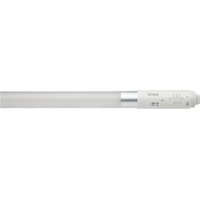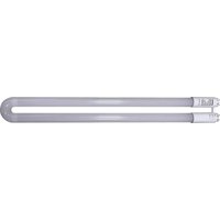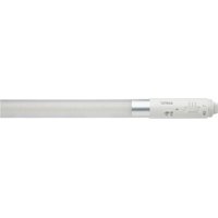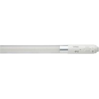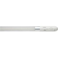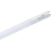
S21762 - Monitor Satco - Free user manual and instructions
Find the device manual for free S21762 Satco in PDF.


User questions about S21762 Satco
0 question about this device. Answer the ones you know or ask your own.
Ask a new question about this device
Download the instructions for your Monitor in PDF format for free! Find your manual S21762 - Satco and take your electronic device back in hand. On this page are published all the documents necessary for the use of your device. S21762 by Satco.
USER MANUAL S21762 Satco
INSTALLATION AND SAFETY INSTRUCTIONS
IMPORTANT: Read before installing fixture. Retain for future reference.
WARNING
- DANGER: Risk of shock. Disconnect power before installation.
Do not install this lamp in a pre-heat luminaire. This lamp only operates on electronic ballasts. If lamp does not light when the luminaire is energized, remove lamp from luminaire and contact lamp manufacturer or qualified electrician. - CAUTION: Risk of fire. If the lamp or luminaire exhibits undesirable operation (buzzing, flickering, etc.), immediately turn off power, remove lamp from luminaire and contact manufacturer.
- WARNING: Risk of fire or electric shock. LED Retrofit Kit installation requires knowledge of luminaire electrical systems. If not qualified, do not attempt installation. Contact a qualified electrician.
- WARNING: Product must be installed in accordance with the national electrical code or your local electrical code. If you are not familiar with these codes and requirements, contact a qualified electrician.
- WARNING: Install this kit only in luminaries that have the construction features and dimensions shown in the photographs and/or drawing and where the input rating of the retrofit kit does not exceed the input rating of the luminaire.
- WARNING: To prevent wiring damage or abrasion, do not expose wiring to edges of sheet metal or other sharp objects.
- Installers should examine all parts that are not intended to be replaced by the retrofit kit for damage and replace any damaged parts prior to installation of the retrofit kit.
- WARNING: Risk of fire or electric shock. Do not use if outer lamp envelope is damaged or broken.
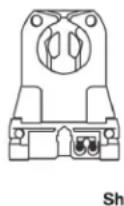
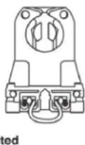
- WARNING: To avoid potential fire or shock hazard, do not use this retrofit kit in luminaries employing shunted bi-pin lampholders. NOTE: Shunted lamp holders are found only in fluorescent luminaries with instant-start ballasts. Instant-start ballasts can be identified by the words "Instant Start" or "I.S." marked on the ballast. This designation may be in the form of a statement pertaining to the ballast itself, or may be combined with the marking for the lamps with which the ballast
is intended to be used, for example F40T 12/IS, for more information contact the LED luminaire retrofit kit manufacturer.
Do not make or alter any open holes in an enclosure of wiring or electrical components during kit installation. Installers should not disconnect the existing wire from lampholder terminals to make new connections at lampholder terminals. Instead installers should cut existing lampholder leads away from the lampholder and make new electrical connections to lampholder lead wires by employing applicable connectors.
- WARNING: Luminaire wiring and electrical parts may be damages when installing retrofit kit hardware. Check for enclosed wiring and components.
- WARNING: Check the existing wiring for damage before installing upgrade kit. Do not install if existing wires are damaged.
The retrofit kit is accepted as a component of a luminaire where the suitability of the combination shall be determined by authorities having jurisdiction. Product must be installed by a qualified electrician in accordance with the applicable and appropriate electrical codes. The installation guide does not supersede local or national regulations for electrical installations.
Operating instructions for double or single ended applications and fixture label are included in this retrofit kit.
- Suitable for damp locations.
- Suitable for use in enclosed luminaries, excluding vapor-tight type fixtures.
- Only use the control provided with or specified by these instructions to control this lamp. This lamp will not operate properly when connected to a standard (incandescent) dimmer or dimming control. Please consult with manufacture for detailed dimmer information.


Features and installation instructions continued on pages 2-5.
| Item Number-Description Volts | Minimum Lamp Compartment Dimensions (Length x Width x Height) | Lamp Quantity | |
| S21760–10T8/LED/24-5CCT/DM/BP-DR | 120-277V | 24 x 22 7/16 x 2 15/16 inches (610 x 570x 75 mm) | 4 |
| S21761–11T8/LED/36-5CCT/DM/BP-DR | 36 1/4 x 22 7/16 x 2 15/16 inches (920 x 570x 75 mm) | ||
| S21762–12T8/LED/48-5CCT/DM/BP-DR | 47 5/8 x 20 7/8 x 3 15/16 inches (1210 x 530 x 100 mm) | ||
| S21763–15T8/LED/48-5CCT/DM/BP-DR |
FEATURES
• c-UL-us classified and Listed
- Two operation modes: Type A (ballast dependant) or Type B (ballast bypass).
• Full glass housing: No aging, yellowing, bending
• PET Shatterproof Coated
APPLICATIONS
Widely used in residential buildings, offices, shopping malls, supermarkets, hospitals, assembly lines, warehouses, etc. for energy saving illumination.
Type A (Mode 1)
- Direct Replacement Mode (Mode 1)
- Plug-n-Play Replacement
- Compatible with instant start electronic ballast
Type B (Mode 2)
- Bypass Mode (Mode 2)
- Direct Connect with the mains: 120-277VAC 50/60Hz (universal voltage input)
Mode 2
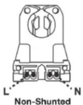
Single Ended

Double Ended
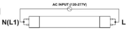
text_image
AC INPUT (120-277V) N(L1) L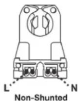
SAFETY PRECAUTIONS
For your safety and the safety of others, please read the precautions carefully before installation.
For Direct Replacement Mode (Mode 1)
- WARNING: Risk of shock. Disconnect power before installation.
- WARNING: Risk of fire, use only in place of fluorescent lamps specified on label. Risk of electric shock. Suitable for damp locations.
- LED T8 lamp for use only with products described and installed in accordance with product specifications. LED T8 lamp to be operated with fluorescent electronic ballast.
- Use for emergency lighting, only with a compatible ballast. To confirm compatibility visit www.Satco.com to view the compatibility chart.
- Type A Mode: This device complies with Part 18 of the FCC Rules. This product may cause interference to radio equipment and should not be installed near maritime safety communications equipment of other critical navigation or communication equipment operating between 0.45-30 MHz.
- Type A LAMP – intended for direct substitution of a fluorescent lamp and operation from the integral ballast without any modifications to the fluorescent luminaire.
For Bypass Mode (Mode 2)
- Product should be installed by qualified electrician.
- Switch off the power supply before commencing work, make sure correct connection before power on.
- Suitable for use with the following emergency equipment; Satco Products Inc., Model S8000, 5W emergency LED driver and Model S8002, 10W emergency LED driver.
- Type B Mode: This device complies with Part 15 of the FCC Rules. Operation is subject to the following two conditions: (1) this device may not cause harmful interference, and (2) this device must accept any interference received, including interference that may cause undesired operation.
- Type B Lamp – intended for operation in luminaires with traditional fluorescent-type lamp holders wired directly to the branch circuit. This includes both factory-wired luminaries as well as those converted for this purpose under a retrofit program.
INSTALLATION: DIRECT REPLACEMENT MODE (Mode 1)
STEP 1: Turn power OFF.
STEP 2: Remove lens or diffuser (if applicable).
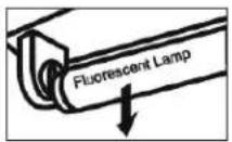
STEP 3: Remove existing fluorescent lamps from the luminaire.
STEP 4: Move the CCT selection switch on the LED lamp to the preferred CCT.
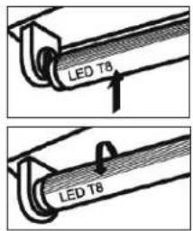
STEP 5: Bring LED lamp to luminaire and insert lamp pins into luminaire lamp holders.
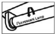
STEP 6: Rotate LED lamp until lamp locks in place.
Ensure that the LED lamp front points away from the back of the luminaire. NOTE: install LED T8 replacement lamp one for each lamp removed.
STEP 7: Replace lens or diffuser (if applicable), and turn power ON.
text_image
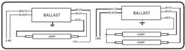
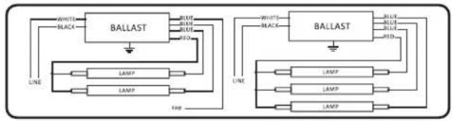
LED T8 LED T8Instant Start Ballast Wiring Diagram
Two Lamps Ballast Correct Wiring
flowchart
graph TD
    subgraph Left_Circuit
        A["BALLAST"] --> B["LINE"]
        A --> C["LAMP"]
        A --> D["Blue"]
        A --> E["RED"]
        A --> F["Black"]
    end
    subgraph Right_Circuit
        G["BALLAST"] --> H["LINE"]
        G --> I["LAMP"]
        G --> J["Blue"]
        G --> K["RED"]
        G --> L["Black"]
    end
    A --> M["Line"]
    G --> N["Line"]
    A --> O["Line"]
Three Lamps Ballast Correct Wiring
flowchart
graph TD
    subgraph Left_Circuit
        A["LINE"] --> B["BALLAST"]
        B --> C["LAMP"]
        B --> D["LAMP"]
        C --> E["Line"]
        D --> F["Line"]
    end
    subgraph Right_Circuit
        G["LINE"] --> H["BALLAST"]
        H --> I["LAMP"]
        H --> J["LAMP"]
        H --> K["LAMP"]
        I --> L["Line"]
        J --> M["Line"]
        K --> N["Line"]
    end
BYPASS MODE (Mode 2)
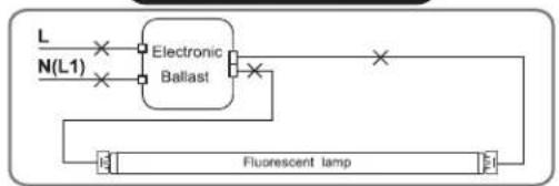
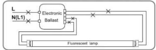
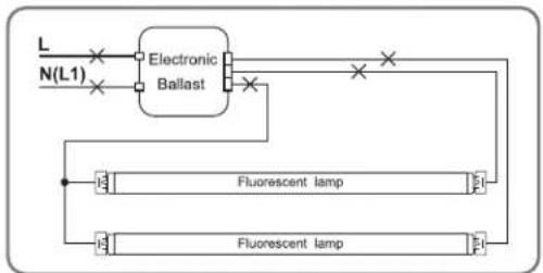
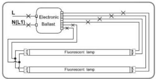
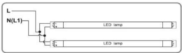
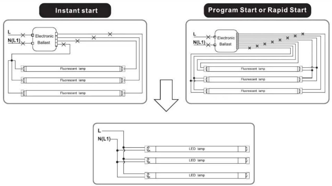
The below ballast wiring represents typical configuration. The actual ballast wiring varies according to ballast model. The socket should be non-shunted.
Single ended Wiring Instruction
Retrofit luminaire with 1 lamp
NOTE: For double ended wiring shunted or non-shunted lamp-holder are compatible. For single ended wiring non-shunted lamp-holders are required.
Instant Start
flowchart
graph TD
    A["L"] --> B["Electronic Ballast"]
    C["N(L1)"] --> B
    B --> D["Fluorescent lamp"]
    D --> E["Output"]

Program Start or Rapid Start
flowchart
graph TD
    A["L"] --> B["Electronic Ballast"]
    C["N(L1)"] --> B
    B --> D["Fluorescent lamp"]
    D --> E["Output"]
    style B fill:#f9f,stroke:#333
    style D fill:#ccf,stroke:#333

text_image
L N(L1) LED lampRetrofit luminaire with 2 lamps
Instant start
flowchart
graph TD
    L["Input L"] --> N["L1"]
    N --> Electronic_Ballast
    Electronic_Ballast --> Fluorescent_Lamp1["Fluorescent lamp"]
    Electronic_Ballast --> Fluorescent_Lamp2["Fluorescent lamp"]
    Fluorescent_Lamp1 --> E1["Output E1"]
    Fluorescent_Lamp2 --> E2["Output E2"]
    E1 --> Fluorescent_Lamp3["Fluorescent lamp"]
    E2 --> Fluorescent_Lamp4["Fluorescent lamp"]

Program Start or Rapid Start
flowchart
graph TD
    A["L"] --> B["Electronic Ballast"]
    C["N(L1)"] --> B
    B --> D["Fluorescent lamp"]
    B --> E["Fluorescent lamp"]
    D --> F["Terminal"]
    E --> G["Terminal"]
text_image
L N(L1) LED lamp LED lampRetrofit luminaire with 3 lamps
Retrofit luminaire with 4 lamps
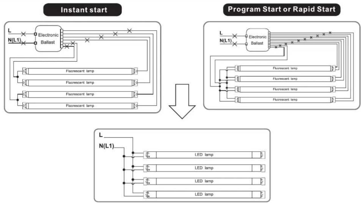
The below ballast wiring represents typical configuration. The actual ballast wiring varies according to ballast model. It is not needed to change socket (if in good condition) to operate double ended lamps, regardless the type of sockets. Please make sure one side of fixture is connected to Live (L) and the other side to Neutral (N). Double ended Wiring Instruction
Retrofit luminaire with 1 lamp
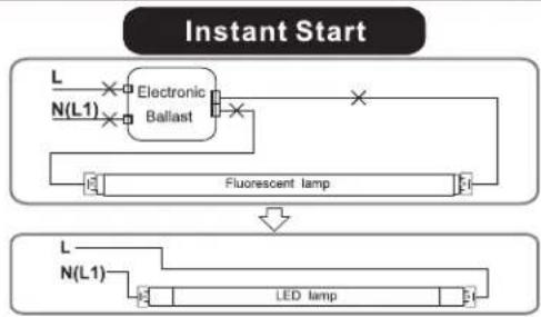
flowchart
graph TD
    A["Instant Start"] --> B["L"]
    A --> C["N(L1)"]
    B --> D["Electronic Ballast"]
    C --> D
    D --> E["Fluorescent lamp"]
    E --> F["LED lamp"]
    F --> G["L"]
    F --> H["N(L1)"]
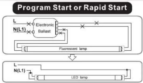
flowchart
graph TD
    A["Program Start"] --> B["L"]
    B --> C["N(L1)"]
    C --> D["Electronic Ballast"]
    D --> E["Fluorescent lamp"]
    E --> F["L"]
    F --> G["N(L1)"]
    G --> H["LED lamp"]
Retrofit luminaire with 2 lamps
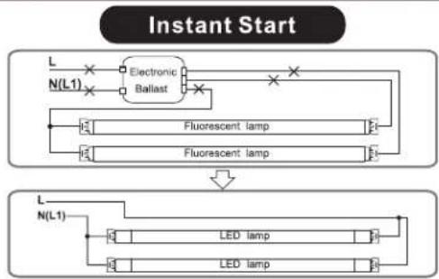
flowchart
graph TD
    A["Electronic Ballast"] --> B["Fluorescent lamp"]
    A --> C["Fluorescent lamp"]
    D["L N(L1)"] --> A
    E["L N(L1)"] --> F["LED lamp"]
    E --> G["LED lamp"]
    style A fill:#f9f,stroke:#333
    style B fill:#ccf,stroke:#333
    style C fill:#ccf,stroke:#333
    style D fill:#cfc,stroke:#333
    style E fill:#cfc,stroke:#333
    style F fill:#fcc,stroke:#333
    style G fill:#fcc,stroke:#333
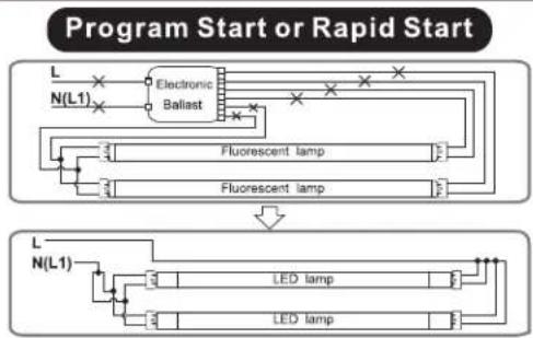
flowchart
graph TD
    A["Program Start"] --> B["L"]
    B --> C["N(L1)"]
    C --> D["Electronic Ballast"]
    D --> E["Fluorescent lamp"]
    E --> F["LED lamp"]
    F --> G["Fluorescent lamp"]
    G --> H["LED lamp"]
    H --> I["LED lamp"]
    I --> J["LED lamp"]
    J --> K["LED lamp"]
    K --> L["LED lamp"]
    L --> M["LED lamp"]
    M --> N["LED lamp"]
    N --> O["LED lamp"]
    O --> P["LED lamp"]
    P --> Q["LED lamp"]
    Q --> R["LED lamp"]
    R --> S["LED lamp"]
    S --> T["LED lamp"]
    T --> U["LED lamp"]
    U --> V["LED lamp"]
    V --> W["LED lamp"]
    W --> X["LED lamp"]
    X --> Y["LED lamp"]
    Y --> Z["LED lamp"]
    Z --> AA["LED lamp"]
    AA --> AB["LED lamp"]
    AB --> AC["LED lamp"]
    AC --> AD["LED lamp"]
    AD --> AE["LED lamp"]
    AE --> AF["LED lamp"]
    AF --> AG["LED lamp"]
    AG --> AH["LED lamp"]
    AH --> AI["LED lamp"]
    AI --> AJ["LED lamp"]
    AJ --> AK["LED lamp"]
    AK --> AL["LED lamp"]
    AL --> AM["LED lamp"]
    AM --> AN["LED lamp"]
    AN --> AO["LED lamp"]
    AO --> AP["LED lamp"]
    AP --> AQ["LED lamp"]
    AQ --> AR["LED lamp"]
    AR --> AS["LED lamp"]
    AS --> AT["LED lamp"]
    AT --> AU["LED lamp"]
    AU --> AV["LED lamp"]
    AV --> AW["LED lamp"]
    AW --> AX["LED lamp"]
    AX --> AY["LED lamp"]
    AY --> AZ["LED lamp"]
    AZ --> BA["LED lamp"]
    BA --> BB["LED lamp"]
    BB --> BC["LED lamp"]
    BC --> BD["LED lamp"]
    BD --> BE["LED lamp"]
    BE --> BF["LED lamp"]
    BF --> BG["LED lamp"]
    BG --> BH["LED lamp"]
    BH --> BI["LED lamp"]
    BI --> BJ["LED lamp"]
    BJ --> BK["LED lamp"]
    BK --> BL["LED lamp"]
    BL --> BM["LED lamp"]
    BM --> BN["LED lamp"]
    BN --> BO["LED lamp"]
    BO --> BP["LED lamp"]
    BP --> BQ["LED lamp"]
    BQ --> BR["LED lamp"]
    BR --> BS["LED lamp"]
    BS --> BT["LED lamp"]
    BT --> BU["LED lamp"]
    BU --> BV["LED lamp"]
    BV --> BW["LED lamp"]
Retrofit luminaire with 3 lamps
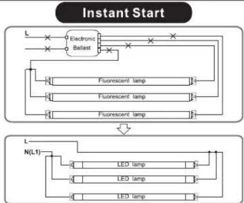
flowchart
graph TD
    A["Electronic Ballast"] --> B["Fluorescent lamp"]
    A --> C["Fluorescent lamp"]
    A --> D["Fluorescent lamp"]
    B --> E["LED lamp"]
    C --> F["LED lamp"]
    D --> G["LED lamp"]
    H["L"] --> A
    I["N(L1)"] --> J["LED lamp"]
    K["Instant Start"] --> L["LED lamp"]

flowchart
graph TD
    A["Program Start or Rapid Start"] --> B["L"]
    B --> C["N(L1)"]
    C --> D["Electronic Ballast"]
    D --> E["Fluorescent lamp"]
    D --> F["Fluorescent lamp"]
    D --> G["Fluorescent lamp"]
    E --> H["L"]
    F --> I["L"]
    G --> J["L"]
    H --> K["LED lamp"]
    I --> L["LED lamp"]
    J --> M["LED lamp"]
Retrofit luminaire with 4 lamps
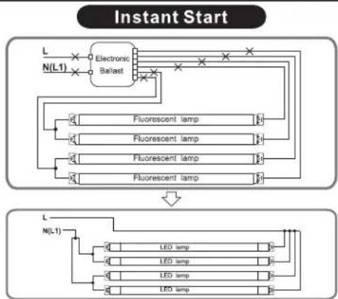
flowchart
graph TD
    A["L"] --> B["Electronic Ballast"]
    C["N(L1)"] --> B
    B --> D["Fluorescent lamp"]
    B --> E["Fluorescent lamp"]
    B --> F["Fluorescent lamp"]
    B --> G["Fluorescent lamp"]
    D --> H["LED lamp"]
    E --> I["LED lamp"]
    F --> J["LED lamp"]
    G --> K["LED lamp"]
    H --> L["Instant Start"]
    I --> L
    J --> L
    K --> L
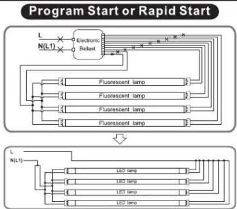
flowchart
graph TD
    A["Program Start or Rapid Start"] --> B["Electronic Ballast"]
    B --> C1["Fluorescent lamp"]
    B --> C2["Fluorescent lamp"]
    B --> C3["Fluorescent lamp"]
    B --> C4["Fluorescent lamp"]
    C1 --> D1["L"]
    C2 --> D2["L"]
    C3 --> D3["L"]
    C4 --> D4["L"]
    D1 --> E1["L"]
    D2 --> E2["L"]
    D3 --> E3["L"]
    D4 --> E4["L"]
    E1 --> F1["L"]
    E2 --> F2["L"]
    E3 --> F3["L"]
    E4 --> F4["L"]
    F1 --> G1["L"]
    F2 --> G2["L"]
    F3 --> G3["L"]
    F4 --> G4["L"]
    G1 --> H1["L"]
    G2 --> H2["L"]
    G3 --> H3["L"]
    G4 --> H4["L"]
ESPAÑOL:
INSTALLATION: MODE DE REMPLACEMENT DIRECT (Mode 1)
ÉTAPE 1: Mettre hors tension (OFF)