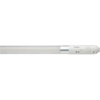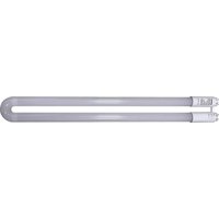
S18411 - Monitor Satco - Free user manual and instructions
Find the device manual for free S18411 Satco in PDF.


User questions about S18411 Satco
0 question about this device. Answer the ones you know or ask your own.
Ask a new question about this device
Download the instructions for your Monitor in PDF format for free! Find your manual S18411 - Satco and take your electronic device back in hand. On this page are published all the documents necessary for the use of your device. S18411 by Satco.
USER MANUAL S18411 Satco
INSTALLATION AND SAFETY INSTRUCTIONS
IMPORTANT: Read before installing fixture. Retain for future reference.
WARNING
- DANGER: Risk of shock-disconnect power before installation.
- WARNING: Risk of fire or electric shock. The electrical rating of these products are 120-277Vac, the installer must determine whether they have 120-277Vac at the luminaire before installation.
- WARNING: Risk of fire or electric shock. LED Retrofit Kit installation requires knowledge of luminaire electrical systems. If not qualified, do not attempt installation. Contact a qualified electrician.
- WARNING: Product must be installed in accordance with the national electrical code or your local electrical code. If you are not familiar with these codes and requirements, contact a qualified electrician.
- WARNING: Install this kit only in luminaries that have the construction features and dimensions shown in the photographs and/or drawing and where the input rating of the retrofit kit does not exceed the input rating of the luminaire.
- WARNING: To prevent wiring damage or abrasion, do not expose wiring to edges of sheet metal or other sharp objects.
- WARNING: To avoid potential fire or shock hazard, do not use this retrofit kit in luminaries employing shunted bi-pin lampholders. NOTE: Shunted lamp holders are found only in fluorescent luminaries with instant-start ballasts. Instant-start ballasts can be identified by the words “Instant Start” or “I.S.” marked on theballast.
This designation may be in the form of a statement pertaining to the ballast itself, or may be combined with the marking for the lamps with which the ballastis intended to be used, for example F40T 12/IS, for more information contact the LED luminaire retrofit kit manufacturer. Do not make or alter any open holes in an enclosure of wiring or electrical components during kit installation. Installers should not disconnect the existing wire from lampholder terminals to make new connections at lampholder terminals. Instead installers should cut existing lampholder leads away from the lampholder and make new electrical connections to lampholder lead wires by employing applicable connectors.
- WARNING: Luminaire wiring and electrical parts may be damages when installing retrofit kit hardware. Check for enclosed wiring and components.
- WARNING: Check the existing wiring for damage before installing upgrade kit. Do not install if existing wires are damaged. This retrofit kit is accepted as a component of a luminaire where the suitability of the combination shall be determined by authorities having jurisdiction. Type B Lamp – this LED tube is intended to replace fluorescent tube lamps with ANSI designation.
- This lamp is dimmable in Type A (Ballast Dependent) mode only. Dimmable ONLY with compatible dimmable ballasts. Visit www.satco.com for compatibility list.
- Suitable for damp locations.
• Not for emergency lighting.


| Item Number-Description | Overall Dimensions (mm) | Operating Temperature | CCT | Volts |
| S18410-13T8U6/LED/CCT/DUAL | 92 x 562.1 x 572.3 -20°C ~ 45°C | 30K, 35K, 40K, 50K | 120V–277V | |
| S18411-13T8/U1/LED/CCT/DUAL | ||||
INSTALLATION: DIRECT REPLACEMENT/PLUG & PLAY (TYPE A)
NOTE: This product my not be compatible with all ballasts. For more information about ballast compatibility visit www.Satco.com.
STEP 1: Turn OFF power before installation.
STEP 2: Remove fixture diffuser (if present) and existing fluorescent lamps from the fixture.
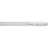
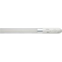
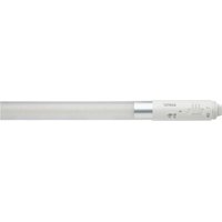
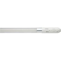
STEP 3: Install the LED U-bend.
STEP 4: Attach the diffuser and turn ON power. Installation is complete.
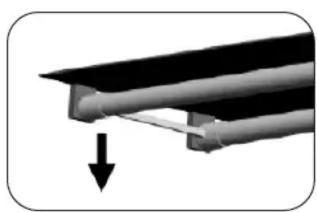
natural_image
Close-up of a mechanical component with a downward arrow indicating force or direction (no text or symbols visible)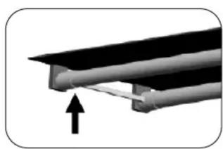
natural_image
Close-up of a mechanical component with a black arrow indicating upward motion (no text or symbols)INSTALLATION: BYPASSING MAGNETIC/ELECTRONIC BALLAST (TYPE B)
STEP 1: Turn OFF power before installation.
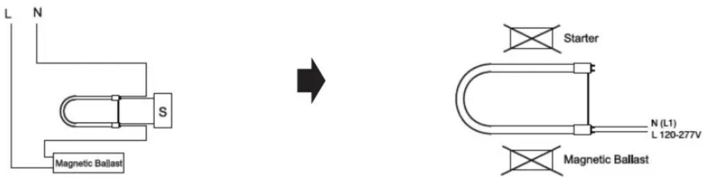
STEP 2: Remove the existing ballast and existing starter (if present) from the fixture.
Magnetic Ballast
text_image
L N S Magnetic Ballast Starter N (L1) L 120-277V Magnetic BallastElectronic Ballast

text_image
L N IS-EB L N RS/PS-EB N (L1) L 120-277V N (L1) L 120-277V IS-EB RS/PS-EBThe wiring can be single end or double end. The connection method refers to Step 3.
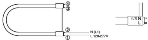
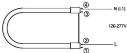
STEP 3: Rewire the fixture to be one certain single end/double end power.
Single End Double End
text_image
④ ③ ② ① N (L1) L 120-277V (L1) N LSingle-end: Leads 1 connected to L; Leads 2 connected to N; Leads 1 and 2 at the end of the lampholder with LN.
text_image
④ ③ N (L1) 120-277V ② ① LDouble-end: Leads 1 or 2 connected to L; Leads 3 or 4 connected to N.
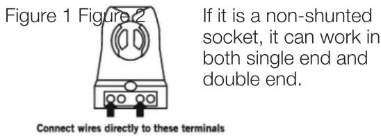
CAUTION: Use only non-shunted lampholders for Single-Ended wiring installations. Do not perform Single-Ended wiring installation of product in a fixture with shunted lampholders (found in all fixtures using instant start ballasts). If the existing lampholders are shunted and Single-Ended wiring is desired, remove and replace them with non-shunted lampholders (or remove the external shunt if applicable). Make new connections directly to lampholder terminals as shown in Figure 1 below. After wiring modification is completed, attach the replacement cautionary label onto a visible place on the fixture and remove any pre-existing labels.
Typical Non-Shunted Lampholder
text_image
Figure 1 Figure 2 If it is a non-shunted socket, it can work in both single end and double end. Connect wires directly to these terminalsTypical Shunted Lampholders
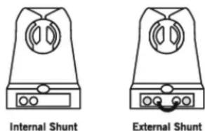
text_image
Internal Shunt External ShuntIf it is a shunted socket, it is double end only,
STEP 4: Install the LED U-bend.
STEP 5: Turn ON power. Installation is complete.