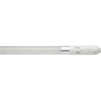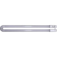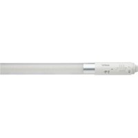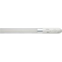
S11929 - Monitor Satco - Free user manual and instructions
Find the device manual for free S11929 Satco in PDF.


User questions about S11929 Satco
0 question about this device. Answer the ones you know or ask your own.
Ask a new question about this device
Download the instructions for your Monitor in PDF format for free! Find your manual S11929 - Satco and take your electronic device back in hand. On this page are published all the documents necessary for the use of your device. S11929 by Satco.
USER MANUAL S11929 Satco
INSTALLATION AND SAFETY INSTRUCTIONS
IMPORTANT: Read before installing fixture. Retain for future reference.
WARNING:
- DANGER: Risk of shock-disconnect power before installation.
- WARNING: Risk of fire or electric shock. LED Retrofit Kit installation requires knowledge of luminaire electrical systems. If not qualified, do not attempt installation. Contact a qualified electrician.
- WARNING: Product must be installed in accordance with the national electrical code or your local electrical code. If you are not familiar with these codes and requirements, contact a qualified electrician.
- WARNING: Install this kit only in luminaries that have the construction features and dimensions shown in the photographs and/or drawing and where the input rating of the retrofit kit does not exceed the input rating of the luminaire.
- WARNING: To prevent wiring damage or abrasion, do not expose wiring to edges of sheet metal or other sharp objects.
- WARNING: NOTE: Shunted lamp holders are found only in fluorescent luminaries with instant-start ballasts. Instant-start ballasts can be identified by the words "Instant Start" or "I.S." marked on the ballast. This designation may be in the form of a statement pertaining to the ballast itself, or may be combined with the marking for the lamps with which the ballast is intended to be used, for example F40T 12/IS, for more information contact the LED luminaire retrofit kit manufacturer.
Do not make or alter any open holes in an enclosure of wiring or electrical components during kit installation.
Installers should not disconnect the existing wire from lampholder terminals to make new connections at lampholder terminals. Instead installers should cut existing lampholder leads away from the lampholder and make new electrical connections to lampholder lead wires by employing applicable connectors.
- WARNING: Luminaire wiring and electrical parts may be damages when installing retrofit kit hardware. Check for enclosed wiring and components.
- WARNING: Check the existing wiring for damage before installing upgrade kit. Do not install if existing wires are damaged.
This retrofit kit is accepted as a component of a luminaire where the suitability of the combination shall be determined by authorities having jurisdiction.
THIS RETROFIT KIT INCLUDES, LED TUBE, OPERATING INSTRUCTIONS, AND FIXTURE LABEL FOR THE DOUBLE OR SINGLE ENDED APPLICATION.
- “This luminaire has been modified and can no longer operate the originally intended lamp,” shall be marked on the retrofit luminaire where readily visible by the user during normal maintenance including lamping.
- Do not use with dimmers.
- Suitable for damp locations.
- Suitable for use in enclosed luminaries, not vapor tight.
- Suitable for use with the following emergency equipment; SATCO Products, Inc., model S8000, S8002; 5Watt or 10 Watt Emergency LED Driver.
- This device complies with Part 15 of the FCC rules. Operation is subject to the following two conditions: (1) This device may not cause harmful interference, and (2) This device must accept any interference received, including interference that may cause undesired operation.


The units covered by this report were intended to retrofit surface mount, Type IC or non-IC recessed mount Listed fluorescent luminaires that use maximum 4 tubular lamps, the minimum lamp compartment dimensions are tabulated below.
| Model Number Volts | Minimum Lamp Compartment Dimensions (Length x Width x Height) | Lamp Quantity | Lamp-to-Lamp Spacing | |
| S11919-12.5T8/LED/48/CCT-SEL/DR S11929-12.5T8/LED/48/CCT-SEL/DR | 120-277V | 47 7/8 x 23 7/8 x 4 inches (121.5 x 60.5 x 10 cm) | 4 | 4 3/8 inches (11cm) |
FEATURES
• c-UL-us classified and recognized
• Full glass housing: No aging, yellowing, bending
APPLICATIONS
Widely used in residential buildings, offices, shopping malls, supermarkets, hospitals, assembly lines, warehouses, etc. for energy saving illumination.
Single Ended Double Ended

text_image
AC INPUT (120-277V) L N (L1)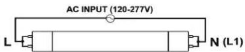
text_image
AC INPUT (120-277V) L N (L1)SINGLE-ENDED WIRING INSTALLATION
Removing Existing Fluorescent System
- Disconnect power from fixture.
- Remove fluorescent lamp(s).
- Remove lens and wiring compartment, if applicable.
- Cut all wires connected to the ballast as shown below and remove ballast.
- Identify what type of lampholders are in fixture. Single-Ended wiring installation of SATCO tubes requires non-shunted G13 lampholders.
- If applicable, replace lampholders with non-shunted lampholders.
Typical Ballast Configurations (NOTE: [x] Indicates where to cut existing wiring.)
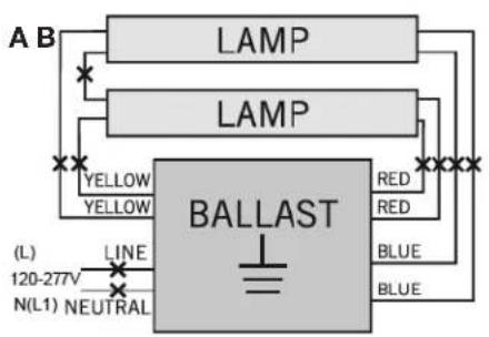
text_image
A B LAMP LAMP YELLOW YELLOW BALLAST RED RED BLUE BLUE (L) LINE 120-277V N(L1) NEUTRAL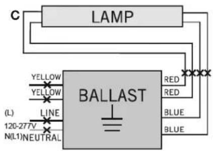
text_image
LAMP BALLAST YELLOW YELLOW LINE (1) 120-27V N(L1)NEUTRAL RED RED BLUE BLUE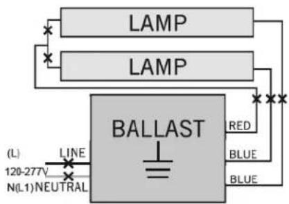
text_image
LAMP LAMP BALLAST RED BLUE BLUE (L) LINE 120-277V N(L1) NEUTRALCAUTION: Use only non-shunted lamp holders for Single-Ended wiring installations.
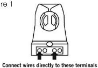
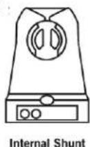
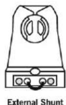
Do not perform Single-Ended wiring installation of product in a fixture with shunted lampholders (found in all fixtures using instant start ballasts, Figure 2). If the existing lampholders are shunted, and Single-Ended wiring is desired, remove and replace them with non-shunted lampholders (or remove the external shunt if applicable). make new connections directly to lampholder terminals as shown in Figure 1 below.
Figure 1
text_image
re 1 Connect wires directly to these terminalsTypical Shunted Lampholders Typical Non-Shunted Lam
Figure 2
Installing the Lamps
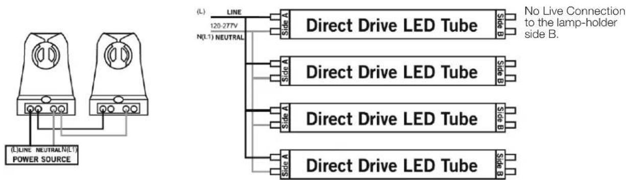
NOTE: For Single-Ended wiring installations, power is only applied to endcap labeled Side A. DO NOT apply power to Side B.
- Confirm that power is still disconnected from fixture.
• Make sure fixture is properly grounded. - Follow STEP 1 for single lamp application or STEPS 2 and 3 for multiple lamp application, based on the number of lamps in the fixture.
Single Lamp
STEP 1: On the Side A lampholder, connect line (L) and neutral N(L1) AC wires to the corresponding pins marked (L) and N(L1) on the endcap. If only one lamp is being installed, proceed to STEP 4.

text_image
(L) LINE 120-277V N(L1) NEUTRAL Direct Drive LED Tube Side A Side B Side B No Live Connection to the lamp-holder side B.Multiple Lamps
STEP 2: Follow the step above for single lamp connection to connect the first lamp.
STEP 3: Connect the terminals on the powered lampholder on the first lamp to the matching terminals on the powered lampholder on the second lamp with line and neutral wires as shown below. Continue daisy-chain connection for each additional lamp.
text_image
(L) LINE NEUTRAL N(L1) POWER SOURCE ( L ) LINE 120-277V N(L1) NEUTRAL Direct Drive LED Tube Side A Side B No Live Connection to the lamp-holder side B. Direct Drive LED Tube Side A Side B Direct Drive LED Tube Side A Side B Direct Drive LED Tube Side A Side BSTEP 4: Complete all electrical connectins with appropriate connectors/wire nuts as needed, per all local and national electrical codes. NOTE: There should not be any exposed wires from sockets left unconnected.
STEP 5: Reinstall wiring compartment cover.
STEP 6: Install all of the SATCO tubes, making sure Side A in installed in the lampholders wired to the line and neutral. Install LED tubes so that the LEDs are pointed in the proper direction for illumination, and install any lens or diffuser as applicable.
STEP 7: Apply power to fixture and check for illumination.
DOUBLE-ENDED WIRING INSTALLATION (Shunted or Non-Shunted Lampholders) Removing Existing Fluorescent System
- Disconnect power from fixture.
- Remove fluorescent lamp(s).
- Remove lens and wiring compartment, if applicable.
- Cut all wires connected to the ballast as shown in diagrams A, B and C on page 2.
- Identify what type of lampholders are in fixture. Double-Ended wiring installation of SATCO tubes can be used with shunted G13 or non-shunted G13 lampholders (with instructions to externally shunt). See Figures 1 and 2 on page 2.
Installing the Lamps
- Confirm that power is still disconnected from fixture.
• Make sure fixture is properly grounded. - Follow STEP 1 for single lamp application or STEPS 2 and 3 for multiple lamp application, based on the number of lamps in the fixture.
Single Lamp
STEP 1: From AC wires, connect line (L) to Side A lampholder and neutral N(L1) to Side B lampholder. If only one lamp is being installed, proceed to STEP 4.
Shunted Lampholders Non-Shunted Lampholder

text_image
(L) LINE Side A 120-277V Direct Drive LED Tube B drive NEUTRALN(L1) 120-277V (L)LINE Side A 120-277V Direct Drive LED Tube Side B NEUTRAL N(L1)Multiple Lamps
STEP 2: Follow the step above for single lamp connection to connect the first lamp.
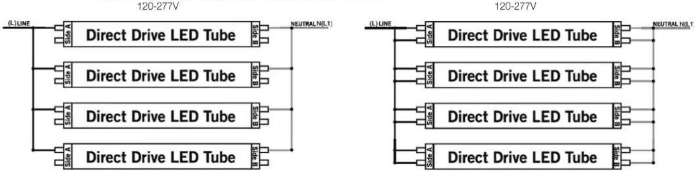
STEP 3: Connect the terminals from the first lamp to the matching terminals on the lampholder of the second lamp with line and neutral wires as shown below. Continue daisy-chain connection for each additional lamp.
Shunted Lampholders Non-Shunted Lampholder
text_image
120-277V L LINE Side A Direct Drive LED Tube side B NEUTRAL N(L1) Side A Direct Drive LED Tube side B Side A Direct Drive LED Tube side B Side A Direct Drive LED Tube side B NEUTRAL N(L1) Side A Direct Drive LED Tube side B Side A Direct Drive LED Tube side B Side A Direct Drive LED Tube side BSTEP 4: Complete all electrical connections with appropriate connectors/wire nuts as needed, per all local and national electrical codes. NOTE: There should not be any exposed wires from sockets left unconnected.
STEP 5: Reinstall wiring compartment cover.
STEP 6: Install all of the SATCO tubes. Install LED tubes so that the LEDs are pointed in the proper direction for illumination, and install any lens or diffuser as applicable.
STEP 7: Apply power to fixture and check for illumination.
ESPAÑOL:
Satco Products, Inc.
Brentwood, NY 11717© Copyright 2021 Se