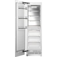
RLD603UFPNS - Refrigerator BERTAZZONI - Free user manual and instructions
Find the device manual for free RLD603UFPNS BERTAZZONI in PDF.


| Product Type | Refrigerator with integrated freezer compartment (column) |
| Brand | Bertazzoni |
| Model | RLD603UFPNS |
| Width | 609 mm (24\") |
| Depth | 635 mm (25\") |
| Height | 2 134 mm (84\") |
| Weight (estimated) | Approximately 100 kg |
| Power supply | 220-240 V ~ 50 Hz, 15 A |
| Refrigerant | R600a (isobutane, flammable) |
| Climate class | SN, N, ST, T (10 °C to 43 °C) |
| Allowed ambient temperature | +10 °C to +43 °C |
| Water connection | Possible for ice maker / dispenser (pressure 1.7-5.5 bar) |
| Door opening | Up to 115° (adjustable to 90° with stop) |
| Door reversibility | Yes (can be changed to opposite side) |
| Adjustable feet | Front and rear, max height 40 mm |
| Custom door panel | Possible, thickness 19 to 38 mm, max weight 30 kg |
| Maintenance and cleaning | Clean the ventilation grilles regularly, automatic defrost |
| Safety | Anti-tip brackets, mandatory grounding, flammable refrigerant |
| Spare parts and repairability | Contact Bertazzoni authorized after-sales service |
| General information | Built-in installation, requires a cabinet niche with precise dimensions |
Frequently Asked Questions - RLD603UFPNS BERTAZZONI
User questions about RLD603UFPNS BERTAZZONI
0 question about this device. Answer the ones you know or ask your own.
Ask a new question about this device
Download the instructions for your Refrigerator in PDF format for free! Find your manual RLD603UFPNS - BERTAZZONI and take your electronic device back in hand. On this page are published all the documents necessary for the use of your device. RLD603UFPNS by BERTAZZONI.
USER MANUAL RLD603UFPNS BERTAZZONI
| EN | INSTALLATION MANUALBUILT-IN COLUMNS | 3 |
| IT | MANUALE D'INSTALLAZIONECOLONNE DA INCASSO | 67 |
| FR | MANUEL D'INSTALLATIONRÉFRIGÉRATEURS ENCASTRABLES | 133 |
| NL | INSTALLATIEHANDLEIDINGINBOUWKOLOMMEN | 199 |
| SV | INSTALLATIONSHANDBOKINBYGGDA KOLONNER | 263 |
FROM THE DESK OF OUR PRESIDENT
Dear new owner of a Bertazzoni appliance,
I want to thank you for choosing one of our beautiful products for your home.
My family started manufacturing kitchen appliances in Italy in 1882, building a reputation for quality of engineering and passion for good food.
Today, our products stand out because of their unique blend of authentic Italian design and superior appliance technology. It is our mission to make products that function perfectly and bring joy to their owners.
By making beautiful products we respond to our customers' flair for good design. By making them versatile and easy-to-use, cooking with Bertazzoni becomes a real pleasure.
This manual will help you learn to use and care for your Bertazzoni appliance in the safest and most effective way, so that it can give you the highest satisfaction for years to come.
Enjoy!
Paolo Bertazzoni
President
Pedro Sectorzou
MANUAL VALIDITY
The following manual is valid for all the product codes mentioned below:
• RLD75S5FPNS
• RLD60S5FPNS
• RFZ45S5FPLS
• RFZ45S5FPRS
RFZ60S5FPNS
GENERAL INFORMATION 7
MANUAL INFORMATION 7
SAFETY INFORMATION 8
CARING FOR THE ENVIRONMENT 8
INSTALLATION 9
CUTOUT DIMENSIONS 9
PRODUCT DIMENSIONS 10
ANTI-TIP BRACKET LOCATION 11
MINIMUM HEIGHT ADJUSTMENT FOR LEVELING 11
FOOD LOAD BEARING CAPACITY OF THE DOOR BINS 12
CUSTOM DOOR PANEL (FOR PANEL-READY MODELS) 13
ELECTRICAL REQUIREMENTS 14
PLUMBING REQUIREMENTS 15
INSTALLATION 17
TOOL LIST 18
ALTERNATIVES FOR INSTALLATION 18
UNPACKING 19
REMOVING THE CONNECTORS ON THE SIDE WALL OF THE UNIT 20
REMOVING THE INSTALLATION HARDWARE 21
REMOVING THE VENT HOLE ASSEMBLY 22
INSTALLATION INSTRUCTION 23
MOUNTING THE ANTI-TIP BRACKETS 23
PREPARING THE WATER HOSE AND THE ELECTRICAL CONNECTION 27
INSTALLATION IN THE CABINET 28
SCREWING IN THE SIDE BRACKETS 33
SECURING THE UPPER BRACKET 34
INSTALLING THE BOTTOM CABINET 35
ATTACHING THE AIR VENT GRILLE 36
ATTACHING THE DECORATIVE TRIM COVERS 36
OVERLAY PANEL INSTALLATION AND PREPARATION 37
HINGE ADJUSTMENT AND REVERSING THE DOOR SWING 48
CABINET CUTOUT DIMENSIONS 57
LOCATION OF THE ELECTRICAL WIRING 58
LOCATION OF THE WATER SYSTEM 59
INSTALLING THE UPPER AND LOWER BRACKETS 61
These instructions are suitable for different types of appliances, so they may contain descriptions of functions which your appliance may not include or support.
The images and illustrations in this document refer to various models and may differ slightly from the product purchased.
The manufacturer does not accept any liability for personal injury or damage to property arising from incorrect installation or misuse of the appliance.
The manufacturer reserves the right to modify the various models as required to comply with the technical regulations in force.
In the event of complaints, please contact customer service. Read the instructions provided in this manual thoroughly before installing and/or using the appliance. This will help you get to know your new appliance. Keep this document at hand so that you can consult it at any moment, and pass it on to any subsequent owners.
Read the safety messages provided in the introduction to this manual and give due consideration to the safety notes, such as: "Attention", "Warning" and "Danger" which appear in the text.

DANGER
This symbol indicates a situation that is a danger to you and others. Read it carefully and make sure that you have perfectly understood the causes of potential dangerous or fatal accidents.

WARNING
This symbol indicates safety information. Read it carefully and make sure that you have perfectly understood the causes of potentially dangerous accidents.

CAUTION
This symbol indicates a procedure which could put the appliance's structure or components at risk. Take particular care over these procedures.

NOTE
This symbol highlights methods or procedures for correct use of the appliance.
The Model, Sales Code and Serial Number are printed on the nameplate. Refer to the Specifications section of this manual for nameplate location.

NOTE
You are advised to make a note of the appliance's data and serial numbers so they are immediately available if required.

NOTE
State the information provided on the nameplate to improve the efficiency of the after-sales and parts services. For warranty purposes, you will also need the date of installation and name of your authorized Bertazzoni dealer.

WARNING
When using your appliance, follow basic precautions. Read all instructions before using the appliance. Save these instructions and pass them on to any future user.
SAFETY INFORMATION

WARNING
This installation manual is intended to aid installation teams. The User Manual provided with the product must also be taken into account.
You may be seriously injured and your product damaged if you ignore the warnings provided in this manual. Please read the following carefully.

WARNING
R600a refrigerant
This product contains R600a isobutane refrigerant, which is a very eco-friendly natural gas. However, it is also flammable.
If the product has been transported horizontally, you must wait for a minimum of 24 hours before plugging it in.
The following instructions must be followed during installation:
- The dimensions of the installation area must be adequate.
- The dimensions, features and position of the object used to support and secure the product in said area must be suitable.
- Minimum clearances between product parts and surrounding structures must be adequate.
- Minimum dimensions and proper positioning of ventilation holes must be heeded.
- The product must be able to be disconnected from the power supply after installation.
- The socket or fuse must be accessible, so as to be able to shut off power to the product.
- Extension cords and ungrounded adapters may not be used. The dimensions of the installation area must be adequate.

CAUTION
You must wear protective gloves and eye protection when installing the product. You must also wear hearing protection when using a drill or similar tools.

CAUTION
Make sure that the electrical circuit is suitable for the product.

CAUTION
The product must be installed by a qualified technician according to the installation instructions.

WARNING
The product may tip over, because it is quite heavy. Precautions must be taken to prevent this from occurring.
The product's doors must be kept closed until it reaches its destination; it must be transported in the manner described in the installation instructions.
CARING FOR THE ENVIRONMENT
The packing materials have been designed to protect the product during transport.
Our appliances are packaged in non-polluting and recyclable materials in accordance with National Environmental Regulations:
- Dispose of packaging in an environmentally friendly manner.
- Please ask your dealer to inquire at your local authority about current means of disposal.
All plastic packing materials, bags, etc. must be disposed of safely and kept out of the reach of children.
The instructions below refer to a built-in installation.
In a built-in installation, the appliance is installed in a cabinet niche or framed in with panels.
Niche Dimensions
- The niche dimensions below must be checked before beginning the installation.
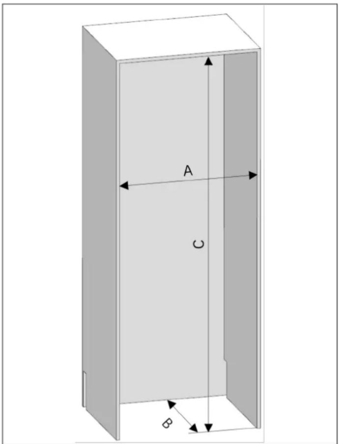
Fig. 1
| CATEGORY | RFZ45S5FPRSR-FZ45S5FPLS | RFZ60S5FPNS RLD60S5FPNS RLD75S5FPNS | |
| A width | 457 mm (18") 609 mm (24") 609 mm (24") 762 mm (30") | ||
| B | depth | 635 mm (25") 635 mm (25") 635 mm (25") 635 mm (25") | |
| C | height | 2134 mm (84") 2134 mm (84") 2134 mm (84") 2134 mm (84") | |
Make sure that the cabinetry inside which you will install the appliance has been securely mounted in your kitchen.
Your cabinet must be properly secured to the floor and to the wall using appropriate mounting hardware.
For the best installation, clearances between the cabinet and the appliance must be in compliance with the measurements specified in the installation instructions.
The side walls must be free of obstructions and their surfaces must be flat. The minimum thickness of the side walls must be 16 mm (5/8"). The minimum thickness of the door panels to be attached to the appliance must be 19 mm (3/4").

NOTE
There is a stainless steel door and stainless toe kick option. Please consult your Authorized Service Provider.
Ventilation openings where the air enters and exits the unit must never be obstructed. The user is responsible for periodically cleaning off the dust and debris that can accumulate on the grill over time.
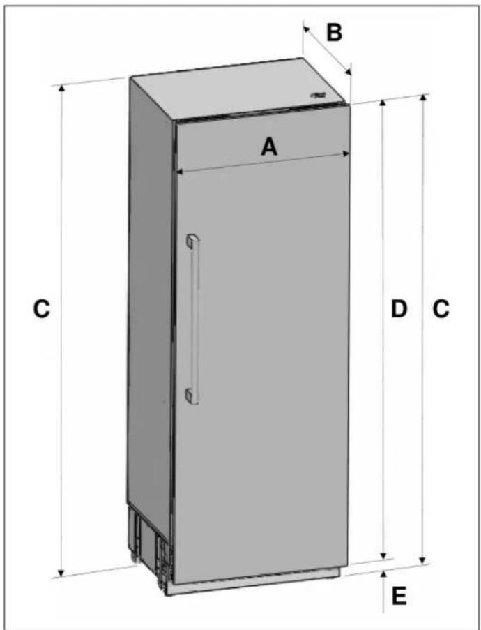
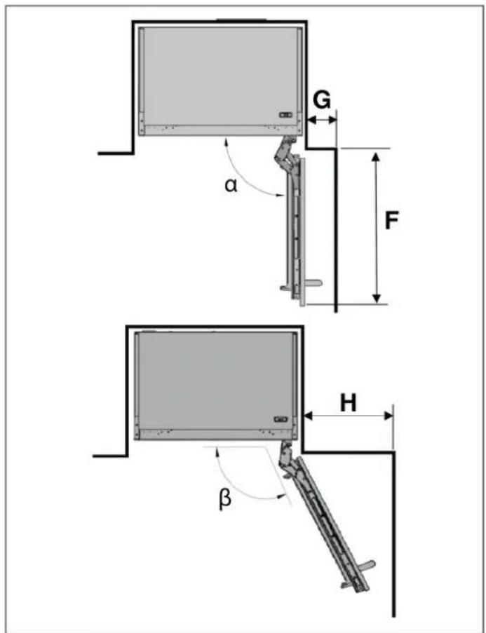
Fig. 2 Fig. 3
α 90°
β 115°
| CATEGORY | RFZ45S5FPRS / RFZ45S5FPLS | RFZ60S5FPNS RLD60S5FPNS | RLD75S5FPNS DESCRIPTION |
| A | 451 mm (17 3/4") 603 mm (23 3/4") 756 mm (29 3/4") | ||
| B | without panel: 592 mm (23 5/16"), with panel: 616 mm (24 1/4") | ||
| C | 2123 mm (83 9/16") | ||
| D | 2030 mm (79 15/16") | ||
| E | 93 mm (3 5/8") | ||
| F | 508 mm (20") 660 mm (26") 813 mm (32") Door depth (90°) | ||
| G | 110 mm (4 3/8") | Minimum door clearance to adjacent wall (90°- reduced internal access) | |
| H | 280 mm (11") 356 mm (14") 406 mm (16") | Minimum door clearance to adjacent wall (115°- full internal access) | |
natural_image
Technical diagram of a mechanical assembly with dimension lines (no text or symbols)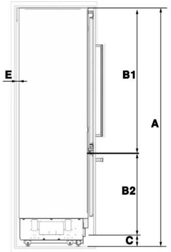
Fig. 4
A B C D E F G H
| 2134 mm(84") | 2030 mm(79 15/16") | 101 mm (4") 3 mm (1/8") |
Remaining
| space after installation: | 2 mm (1/16") | 574 mm(22 5/8") | 42 mm(1 5/8") |
19 mm (3/4")
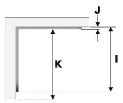
ANTI-TIP BRACKET LOCATION
| IJK | |
| 2134 mm (84") 4 mm (5/32") | 2130 mm (83 7/8") |
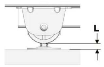
MINIMUM HEIGHT ADJUSTMENT FOR LEVELING
| L | |
| Front | 8 mm (5/16") |
| Rear | 7 mm (1/4") |
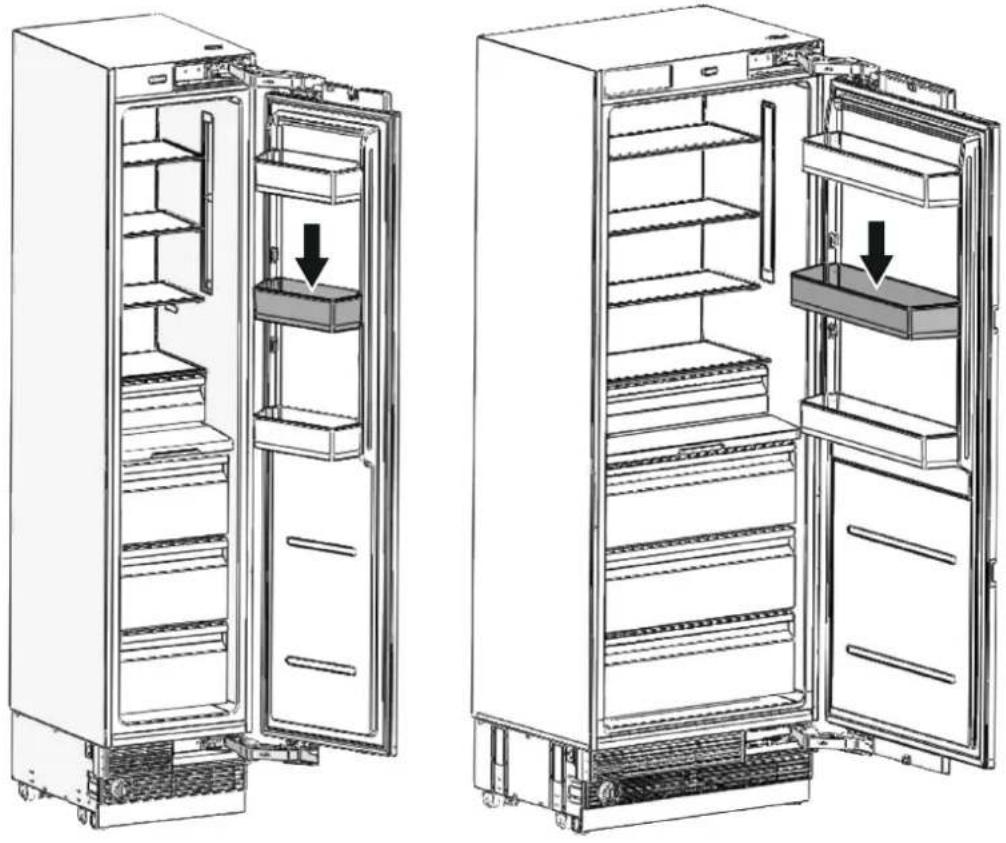
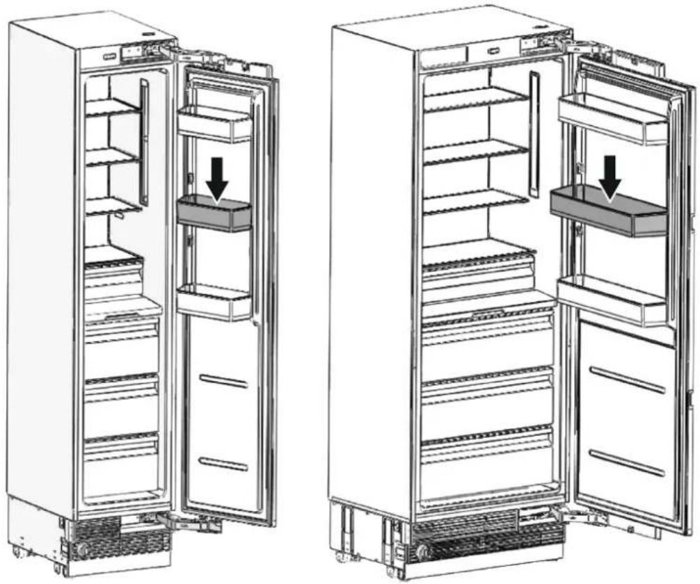
FOOD LOAD BEARING CAPACITY OF THE DOOR BINS
natural_image
Two line drawings of an open refrigerator with doors open, showing internal shelves and storage compartments (no text or symbols)Fig. 5
CATEGORY
RFZ45S5FPRS / RFZ45S5FPLS
RFZ60S5FPNS RLD60S5FPNS RLD75S5FPNS
Max. load
10 kg (22 lbs) 15 kg (33 lbs) 15 kg (33 lbs) 15 kg (33 lbs)
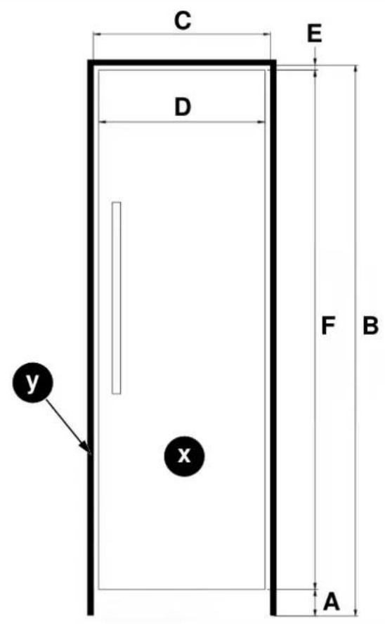
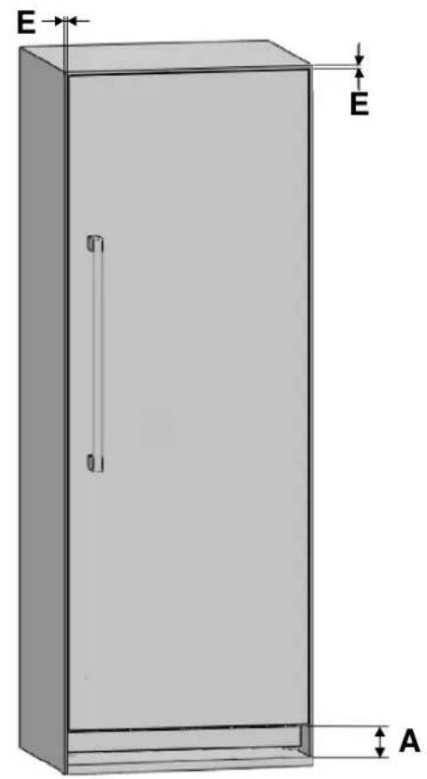
Fig. 6
• x: WOOD DOOR PANEL
y: WOOD CABINET
Based on the cabinet cutout height, the kitchen toe kick can be installed with following heights:
CATEGORY A B
| standard | 101 mm (4") 2134 mm (84") |
| minimum | 96 mm (3 3/4") 2129 mm (83 13/16") |
| maximum | 136 mm (5 3/8") 2169 mm (85 3/8") |
CATEGORY C D E F
| RFZ45S5FPRS / RFZ45S5FPLS | 457 mm (18") 451 mm (17 3/4") | 3 mm (1/8") 2030 mm (79 15/16") |
| RFZ60S5FPNS | 609 mm (24") 603 mm (23 3/4") | |
| RLD60S5FPNS | 609 mm (24") 603 mm (23 3/4") | |
| RLD75S5FPNS | 762 mm (30") 756 mm (29 3/4") |
The location of the electrical outlet in the cabinet where the product is to be installed must be within the area shown in the figure.

CAUTION
Do not use extension cords or two-prong adapters and do not remove the ground terminal of the grounding cable.

CAUTION
A qualified electrician must ensure that the poles of the socket are connected correctly.
Verify that the grounding of the socket is correct.
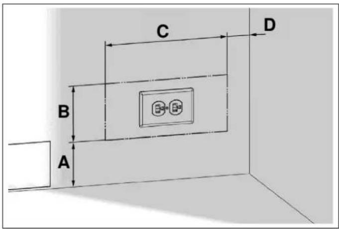
Fig. 7
A 102 mm (4")
B 127 mm (5")
C 280 mm (11")
D 50.8 mm (2")

WARNING
Do not connect the appliance to electronic energy saver plugs.
The socket must comply with the following data:
ELECTRICAL REQUIREMENTS
| Plug type | SCHUKO |
| Power cord 2-prong | |
| Voltage 220 V – 240 V | |
| Frequency 50 Hz | |
| Fuse 15 A |
After installation, wait at least 3 hours before connecting the appliance to the electrical power to avoid damaging the compressor.

IMPORTANT
Do not use extension cords and/or multiple adapters for the power supply connection.
If the electrical wiring or the electric power supply of the house requires alteration, the necessary procedures must be performed by a qualified electrician.
Please heed the following rules:
- The electrical outlet or panel must be easily accessible in case of an emergency; it must not be hidden behind the product.
Neither the plug nor the cable may touch the back surface of the appliance. Otherwise, it may be damaged by the appliance's vibrations. - Do not connect other equipment plugs behind this appliance. If the humidity level is high where the appliance is being used, its exterior surfaces may become corroded. To prevent corrosion, keep the installation room dry and well-cleaned.
To prevent the risk of electric shock:
Connect the plug to a grounded outlet.
Do not remove plug's grounding prong.
Do not use adapters.
Do not use extension cords.

CAUTION
Do not connect the grounding cable to the gas line. Please have the grounding checked by a qualified electrician if you are not sure about the grounding of the appliance. Do not install a fuse on the neutral line or on the grounding circuit.

CAUTION
Failure to follow these instructions may result in fire, electric shock or death. Connecting the appliance's grounding conductor in the wrong place may lead to electric shock. Please have the grounding checked by a qualified electrician or service technician if you have any doubt about the proper grounding of the appliance. Installation, repairs and other procedures performed by unqualified persons may give rise to hazards. Before installing the appliance, make sure that the voltage, load and circuit current parameters on the data plate are in compliance with the power supply in your house.
Models equipped with an Ice Maker and/or a Water Dispenser require a connection to the domestic water supply system.

NOTE
Take the necessary measures to prevent the risk of freezing of the hoses. The operating water temperature range is between a minimum of 1^ C ( 34^ F) and a maximum of 38^ C ( 100^ F).
The system pressure must be:
• Min. 1.7 bar (25 psi)
• Max. 5.5 bar (80 psi)
Any pressure outside of this range may cause the water system to malfunction or leak. If the water pressure exceeds the maximum value, install a pressure limiting valve to your mains system. If the water mains pressure is lower than the minimum value, it is possible to use an auxiliary pump.
If you do not know how to check the water pressure, please consult a professional plumber.

WARNING
This appliance should only be connected to a drinking water system.

WARNING
The location of the water line connection must be within the area shown in the figure below.

WARNING
The refrigerator's water system must be connected to the house's main water supply.

WARNING
The user must be able to switch it on/off using the valve when necessary.

WARNING
Make sure that installation is performed correctly and in accordance with all the instructions in the specific installation manual provided with the appliance.

WARNING
Do not attempt to use a locally sourced threaded garden hose adapter or braided supply line. It will strip the threads on the appliance's water connection solenoid.

NOTE
A bypass plug is recommended for the water filtering system if a reverse osmosis system is used.

WARNING
Make sure that there is no water leakage when establishing the water connections. Otherwise, water may damage the cabinetry. The water supply line must located in the cabinet where the appliance is to be installed. The user must be able to switch it on/off using the valve when necessary.
You will need a hose with a minimum length of 1.5 m (60") and a diameter of 6.4 mm ( 14 ") for the appliance's water connections during installation. A connector that has a thread with an external diameter of 6.4 mm ( 14 ") must be used to connect the end of the hose to the product.
Before completing the installation, make sure that water flows and that there is no water leakage.
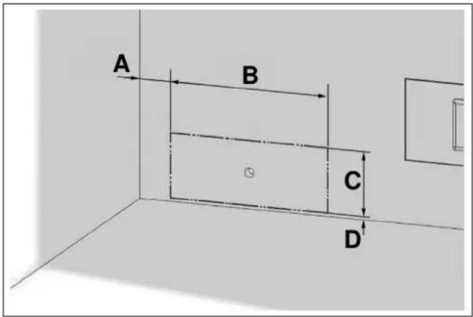
Fig. 8
A 50.8 mm (2")
B 254 mm (10")
C 102 mm (4")
D 6 mm (1/4")
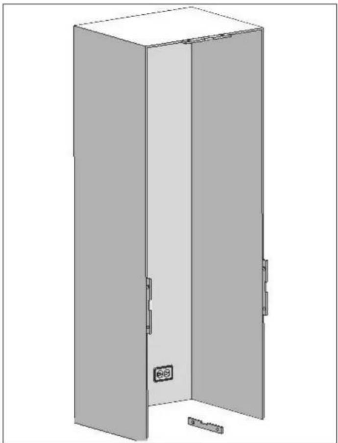
natural_image
3D line drawing of a cabinet with open door and internal compartments (no text or symbols)Fig. 9

WARNING
• The level of the floor where the product is to be installed must be checked with a bubble level.
- The cabinet flanges must be checked with a bubble level to ensure that they are perfectly vertical.
- If the appliance is not perfectly level and vertical, problems may arise with the installation.
Make sure that the installation is performed correctly, in accordance with all the instructions in the specific installation manual provided with the appliance.

WARNING
Always connect the water before connecting the power.
For a correct installation, please follow the instructions below:
- The floor on which the product is to be installed must be capable of bearing 544 kg (1,200 lb) minimum.
- The kitchen floor and the bottom of the product must be equally level. Otherwise, problems may occur with the appliance's air flow.
- There must be no obstructions at the rear and on the side walls of the product's installation location that would prevent its installation.
• The electrical outlet must be in the correct place.
- The dimensions of the cabinet where the appliance is to be installed must be in strict conformity with the dimensions provided in the manual.
- Do not install the appliance adjacent to another fridge/freezer. Otherwise, condensation and damage may occur. For a side-by-side installation, use the proper connection kit.
- The level of the floor where the product is to be installed must be checked with a bubble level.
- The installation location must not be exposed to direct sunlight and must be away from heat sources (ovens, radiators, etc.).
- The ambient temperature must be between 10°C (50°F) and 43°C (110°F). Otherwise, malfunctions may occur when the appliance is running.
- If it is not possible to avoid installing the product near a heat source, the minimum clearances provided below must be maintained between the appliance and the given source:
- 32 mm (1 1/4") from electric ranges or ovens
- 305 mm (12") from gas or fuel-powered hobs or ovens.
- Position the appliance with the aid of a second person.
- Never use the open door to lever the appliance into place when fitting.
- Avoid exerting too much pressure on the door when open.
- Do not use the appliance outdoors.
- Installation and servicing should be carried out by qualified personnel in accordance with current standards.
- Ensure that an authorized technician performs the electrical connection.
- If the power supply cable is damaged, ensure against hazards by contacting technical support immediately and they will replace it, so as to prevent any risk.
- Always put on the necessary/required Personal Protective Equipment (PPE) before performing any work on the appliance (installation, maintenance, positioning, or movement).
Before performing any operation involving the appliance, switch off the power supply. - This appliance can be used up to a maximum altitude of 4,000 metres above sea level.
Do not try to repair the appliance yourself or without the assistance of a qualified technician.
Do not install/use the appliance outdoors. - To ensure the appliance is stable, install and secure it correctly as described in the instructions provided in this manual.

CAUTION
Make sure that the power supply cable does not become caught or damaged when positioning the appliance.

CAUTION
Do not install your refrigerator:
• in an outdoor space,
• in a location with dripping water,
- in a location where the temperature is lower than 10°C (50°F).
The permitted room temperature depends on the climate class:
| CLIMATE CLASS | PERMITTED ROOM TEMPERATURE |
| SN (Sub Normal) | + 10 °C to + 32 °C |
| N (Normal) | + 16 °C to + 32 °C |
| ST (Sub Tropical) | + 18 °C to + 38 °C |
| T (Tropical) | + 18 °C to + 43 °C |
Information on the climate class can be found on the rating plate.
TOOL LIST
The tools to be used when installing the product are as follows:
Cordless drill
Safety goggles
12.7 mm (1/2") spanner
Hammer
Ladder
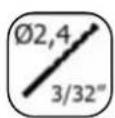
∅ 2.4 mm drill bit
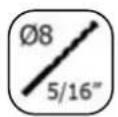
∅ 8.0 mm drill bit
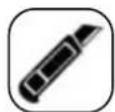
Box cutter

Safety gloves Tap

Phillips-head bit
6.4 mm (1/4") hex bit
Bubble level
Appliance
trolley

Tape

T25 Torx Bits
ALTERNATIVES FOR INSTALLATION
The appliance can be installed in a variety of ways depending on the kitchen design. It must be installed in a location where it is certain that the door can be opened and closed properly. If the doors cannot open up to at least 90 degrees the appliance drawers will not be able to be opened.
Single-fridge cabinet placement methods
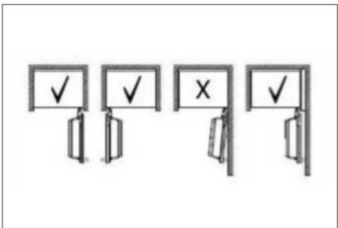
Fig. 10
Dual-fridge cabinet placement methods.
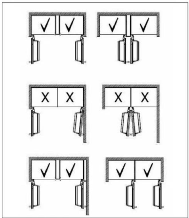
Fig. 11
UNPACKING

WARNING
At least two people must carry the refrigerator.
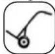
- Use a box cutter to remove the tape.
- Cut the cardboard packaging along the dotted lines using a box cutter and remove it.
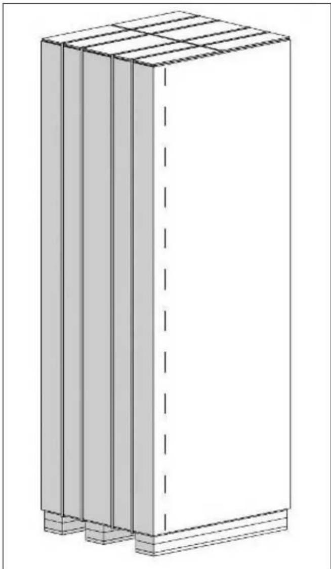
natural_image
3D architectural rendering of a rectangular building with vertical supports and horizontal beams (no text or symbols)Fig. 12
- Remove the polystyrene packing material.
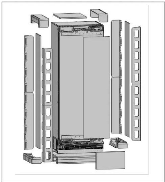
natural_image
Exploded view diagram of a refrigerator internal structure (no text or labels)Fig. 13

CAUTION
Do not discard the foam insulation pad included with freezer and wine columns with the rest of the packaging. It is required when installing two or more columns side-by-side. Failure to use the insulation pad may result in unwanted condensation.

CAUTION
Do not remove the tape from the upper door of the appliance until the refrigerator is placed in the cabinet.
Tipping risk.
REMOVING THE CONNECTORS ON THE SIDE WALL OF THE UNIT
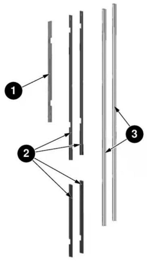
flowchart
graph TD
    A["1"] --> B["2"]
    B --> C["3"]
    style A fill:#f9f,stroke:#333
    style B fill:#ccf,stroke:#333
    style C fill:#cfc,stroke:#333
Fig. 14
| NO. | PART NAME SPECS | RFZ45S5FPRS / RFZ45S5FPLS | RFZ60S5FPNS / RLD60S5FPNS | RLD75S5FPNS | |
| PVC extrusion L=457 1 | |||||
| 1 | Trim furniture top | PVC extrusion L=609 1 | |||
| PVC extrusion L=761 1 | |||||
| 2 | Trim furniture side | PVC extrusion L=1.259 2 2 2 | |||
| PVC extrusion L=617 2 2 2 | |||||
| 3 | Trim door side PVC extrusion L=1.781 2 2 2 | ||||
REMOVING THE INSTALLATION HARDWARE
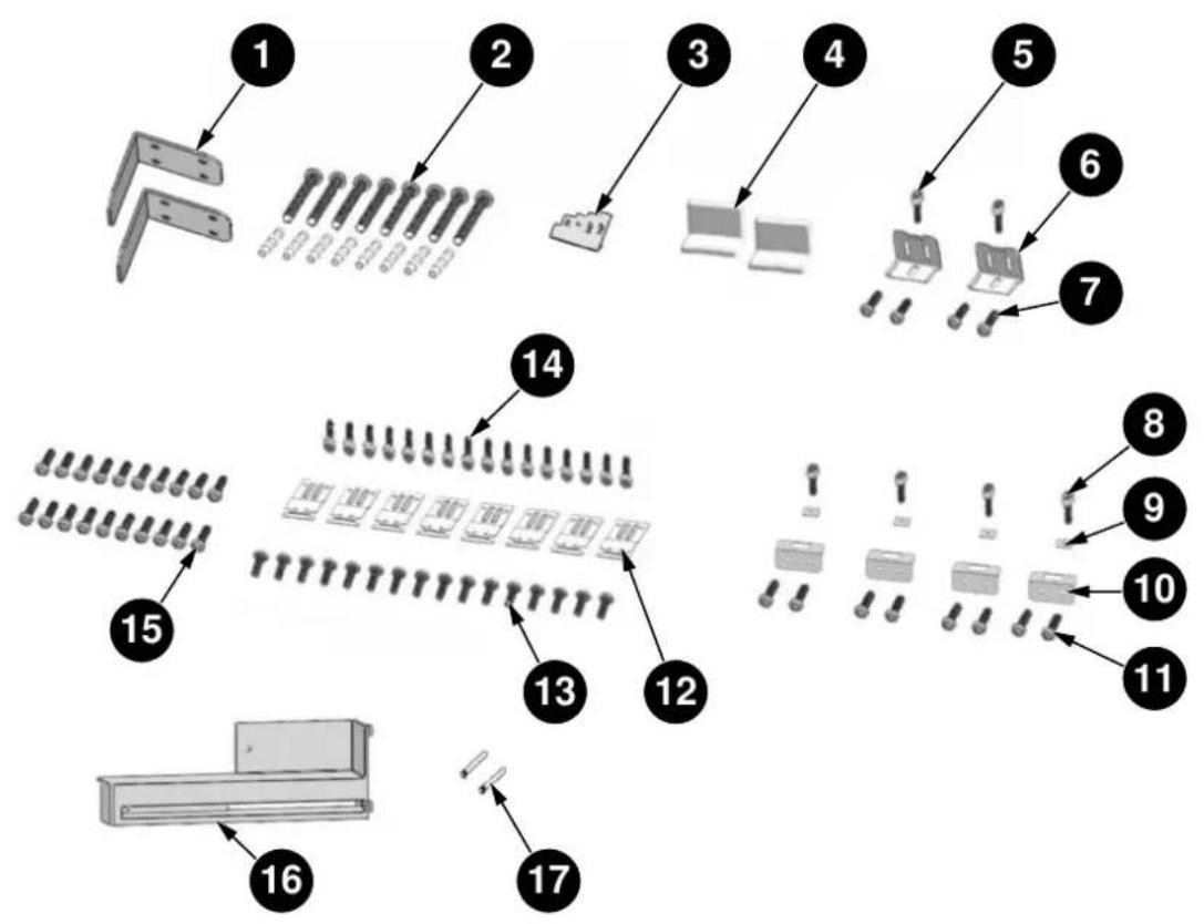
flowchart
graph TD
    A["1"] --> B["2"]
    B --> C["3"]
    C --> D["4"]
    D --> E["5"]
    E --> F["6"]
    F --> G["7"]
    G --> H["8"]
    H --> I["9"]
    I --> J["10"]
    J --> K["11"]
    K --> L["12"]
    L --> M["13"]
    M --> N["14"]
    N --> O["15"]
    O --> P["16"]
    P --> Q["17"]
Fig. 15
| NO. | PART NAME SPECS | RFZ45S5FPRS / RFZ45S5FPLS | RFZ60S5FPNS / RLD60S5FPNS RLD75S5FPNS | DESCRIPTION | |
| 1 | Anti-tip bracket T4.0, Cr+zn-coating | 8 | 8 | ||
| 2 | Anti-tip bracket screws | M8xL60 8 8 | |||
| 3 | Position adjustment jig | PS 1 1 | |||
| 4 | Cover furniture door bracket | ABS | - | 2 | Screws for the refrigerator |
| 5 | Truss washer head | M4x12 | - | 2 | |
| 6 | Bracket furniture door | T1.0, Cr+zn-coating - | 2 | ||
| 7 | Counter sunk head screw | ST4x14 | - | 4 | |
| 8 | Crossed flat head screw | M4x12 4 4 | |||
| 9 | Square washer T1.0, Cr+zn-coating | 4 | 4 | ||
| 10 | Center mounting bracket | T1.0, Cr+zn-coating | 4 | 4 | |
| NO. | PART NAME SPECS | RFZ45S5FPRS / RFZ45S5FPLS | RFZ60S5FPNS / RLD60S5FPNS RLD75S5FPNS | DESCRIPTION | |
| 11 | Crossed flat head screw | M4x12 8 8 | |||
| 12 | Bracket furniture | T1.0, Cr+zn-coating | 8 | 8 | |
| 13 | Counter sunk head screw | ST M4x14 16 16 | Screws for wood furniture | ||
| 14 | Crossed flat head screw | M4x12 16 16 | |||
| 15 | Counter sunk head screw | ST M4x14 16 20 | Furniture door hanging bracket | ||
| 16 | Air vent hinge part | ABS | - | 1 | Door opening direction change |
| 17 | 90° limit pin | ∅4 1 1 | Door 90° opening use | ||
REMOVING THE VENT HOLE ASSEMBLY
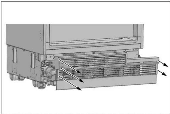
- Remove 5 screws to take out the Vent Hole Assembly.
natural_image
Technical diagram of an air conditioner unit with airflow arrows indicating internal components (no text or symbols present)Fig. 16
MOUNTING THE ANTI-TIP BRACKETS

WARNING
If the unit cannot be secured to the cabinetry (which in turn must be secured to wall) to prevent tipping, make sure to use the supplied anti-tip brackets in order to prevent the appliance from tipping over.

WARNING
Make sure that there is no electrical or water connection in the adjacent cabinets into which the mounting screws will be screwed to secure the refrigerator.

WARNING
Please remember to use the necessary protective equipment when drilling holes in the wall and performing the installation.
- Use a tape measure to mark the wall for installation of the anti-tip brackets.

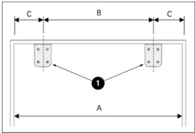
Fig. 17
1 Anti-tip bracket, on the wall
| CATEGORY | RFZ45S5FPRS / RFZ45S5FPLS | RFZ60S5FPNS | RLD60S5FPNS | RLD75S5FPNS |
| A | 457 mm (18") | 609 mm (24") | 609 mm (24") | 762 mm (30") |
| B | 295 mm (11 5/8") | 447 mm (17 5/8") | 447 mm (17 5/8") | 600 mm (23 5/8") |
| C | 81 mm (3 3/16") | 81 mm (3 3/16") | 81 mm (3 3/16") | 81 mm (3 3/16") |
- For the most secure installation, use a stud-finder to secure the anti-tip brackets in wall studs. If no studs are present at the correct installation location, follow the instructions below.

WARNING
Always make sure that the area to be drilled into is free of any waterlines or electrical circuits, which could cause damage, injury, or death.
- Use a drill to create holes for wall anchors (#2) at the marked points ∅ 8 mm (∅ 5/16").
Use a drill to create holes for wall anchors (#2) at the marked points ∅ 5/16" (∅ 8 mm).
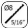

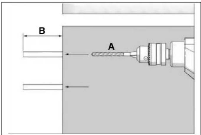
Fig. 18
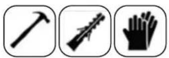
- Use a hammer to install the wall anchors (#2) if no stud is present.
natural_image
Three black-and-white icons: a hammer, a rifle, and a glove, arranged horizontally within rounded square frames (no text or symbols)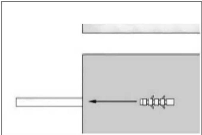
natural_image
Pure diagram of a mechanical or electrical component with no text, numbers, or symbolsFig. 19
• Install the brackets (#1) in place, using 4 screws for each.
- You must use both (two) brackets to ensure that the appliance is safely supported.

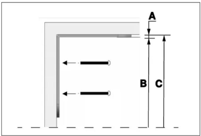
Fig. 20
• A Thickness

NOTE
If you are not confident that the supplied connectors and anti-tip brackets are mounted on the wall as securely as they should be, you can use alternative anti-tip methods.
If there is a cabinet panel behind the back wall of the refrigerator, make sure that it is securely fastened to the wall. For this, you need to be sure that the back wall of the cabinet panel is affixed to a wall stud.
Alternative anti-tip method:
If the anti-tip brackets cannot be mounted securely, you must use the alternative method below. For this method, you can use wooden boards to avoid the risk of tipping over.
They must be installed as illustrated in the figure below.
There must be no clearance between the appliance and the wooden support.
The minimum section dimensions of the wooden support must be 76 mm x 102 mm (3" x 4"). The width of the support must be equal to the clearance where it will be installed. This can be achieved using one 102 mm x 102 mm (4" x 4") or two 51 mm x 102 mm (2" x 4") pieces of framing lumber.
The calculation of blocking depth is based on a standard niche depth. If the depth of the niche is greater than 610 mm (24"), ensure the blocking overlaps the upper rear fridge body by 51 mm (2").
Position the wooden support, mark the location on the rear wall, select suitable screws and mount it securely.

WARNING
The quantity and type of screws or fasteners to be used for affixing wooden blocking must be suitable for ensuring a secure connection to the rear wall.
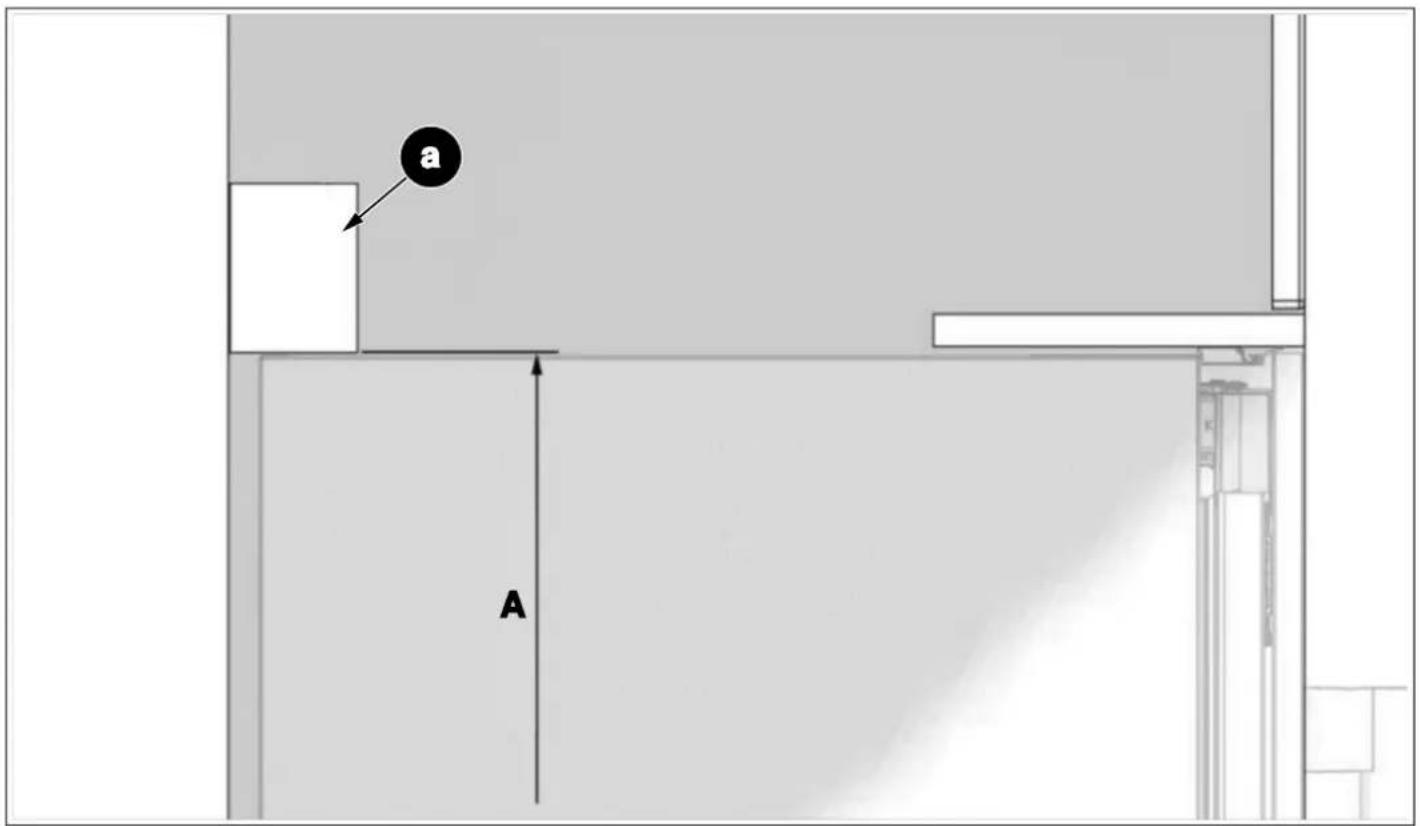
Fig. 21
A 76 mm x 102 mm (3" x 4")
PREPARING THE WATER HOSE AND THE ELECTRICAL CONNECTION
Inspect all water connections for leaks. Water leaks can cause significant damage over time. It is recommended to use a 6.4 mm (1/4") water line with a minimum length of 1.5 metres (60") with a threaded 6.4 mm (1/4") female connector end. Before finishing the installation, turn the water on to ensure that water is flowing and that there are no leaks.
A connector that has a thread with an external diameter of 6.4 mm (1/4") must be used to connect the end of the hose to the product.
Allow for sufficient slack in the water supply line, providing a minimum of 254 mm (10") of length from the base of the unit once it is installed in the niche. This provides some allowance for connections and adjustments if needed.
The product must be connected to a 2-prong outlet on a dedicated 15 amp circuit; local electrical and building codes should be respected.
You can choose method A or method B below to prevent the power cord from getting wedged in.
• Method A: Position the water hose and the mains power connections on the back of the refrigerator.
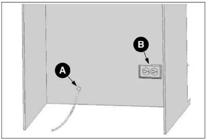
Fig. 22
A Water line location
• B Power cord location
Method B: Position the water hose and mains power connections on the sides of the cutout.
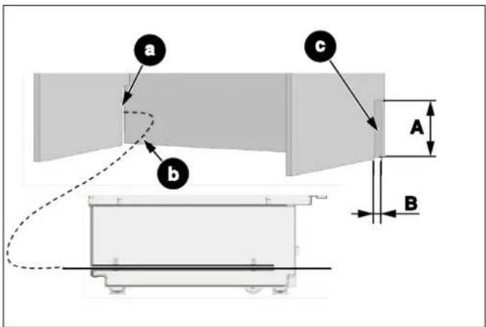
Fig. 23
a. Keep open for water line
b. Water hose
c. Keep open for power cord
A. 203 mm (8")
B. 51 mm (2")
INSTALLATION IN THE CABINET
Taking the Refrigerator from the Wooden Pallet
- Remove the brackets which secure the refrigerator to the wooden pallet as shown below.
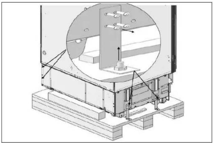
natural_image
Technical diagram of a mechanical assembly with circular component and mounting base (no visible text or symbols)Fig. 24
- Slowly tilt the refrigerator back and remove it from the pallet, taking care not to damage the underside of the unit. When transporting the unit, always carry it from the sides to ensure that the unit's feet remain on the base of the appliance dolly.
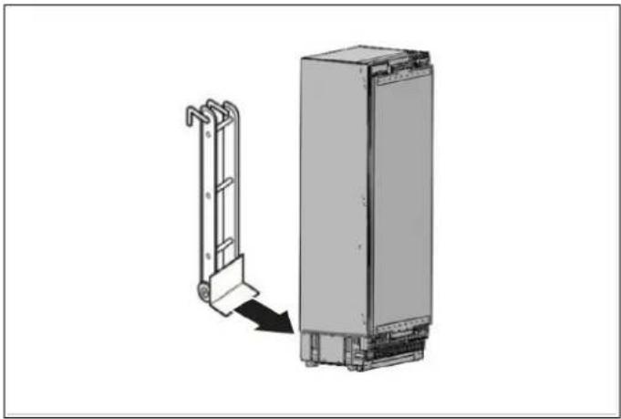
natural_image
Diagram showing a mechanical device with a bracket and a vertical panel, no text or symbols presentFig. 25

NOTE
Exercise extreme caution when handling the unit, as the underside of the fridge has components vital to its proper operation; damage to these components could result in a malfunction or potential leakage of condensate and damage to floors.

CAUTION
The risk of tipping over is high from this point forward. You should not open the doors until the product is placed into the cabinet.
Placing the refrigerator into the cabinet niche.
- Insert the water supply hose into the channel opening at the back of the unit and pull it through to the front of the unit to ensure that the water connection can be made once the unit is installed in the niche.
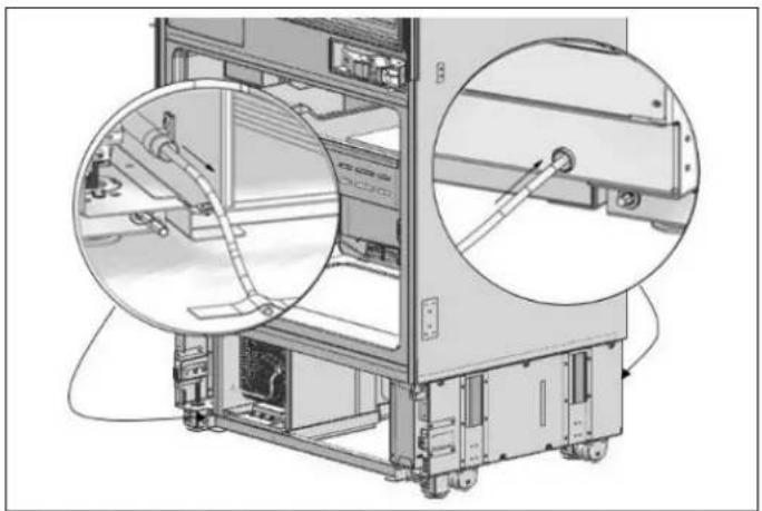
natural_image
Technical illustration of a server rack with zoomed-in views showing internal components (no text or symbols)Fig. 26

NOTE
Use the method below to prevent the cord from getting wedged in.
Connect the electrical plug to the power outlet. Turn on the unit to ensure it has power (to see if the product is operating, check if the lamps in the freezer compartment are on or off).
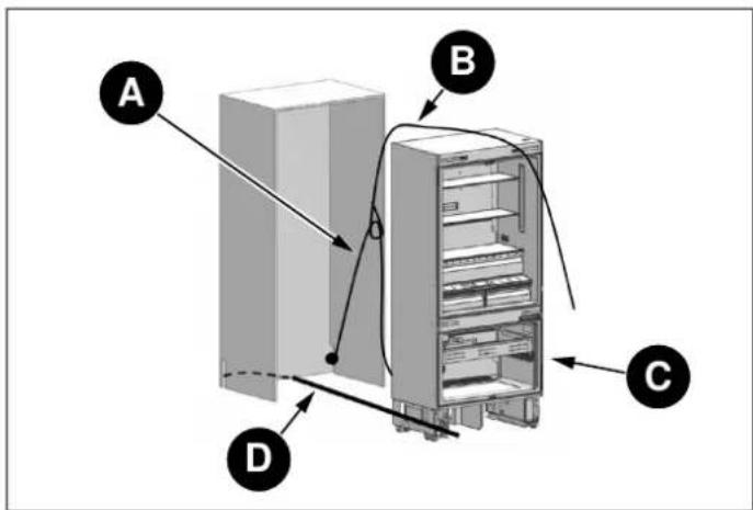
Fig. 27
A Power cord
B Nylon cord
C Move to wall
D Water hose
Connect the electrical plug to the power outlet. Turn on the unit to ensure it has power. (To see if the product is operating, check if the lamps in the freezer compartment are on or off).

NOTE
Protect the front edges of the cabinet niche with masking tape; this will help protect them from damage when pushing the unit back into the niche. Use some packing tape to secure the excess electrical cord to the back of unit to prevent slack from catching under the unit during installation.

NOTE
The unit's plug must be accessible after installation. If the plug is not accessible after installation, the power must have a dedicated circuit breaker which can be accessed to cut power off using the main switch.

WARNING
• Make sure that the power cord does not get wedged in when placing the product.
- Push the product carefully towards the cabinet to position it; the unit should slide into the niche with relative ease. If you experience resistance while placing the product in the cabinet:
• The floor might be uneven.
- The adjustable feet might be loose (please see the relevant section to learn how to adjust the adjustable feet).
- You must attach the freezer door temporarily to align the product before placing it.

NOTE
Use the upper edges of the fridge and freezer doors to align the unit in the niche opening.
Adjustment of other edges is explained in the following pages.
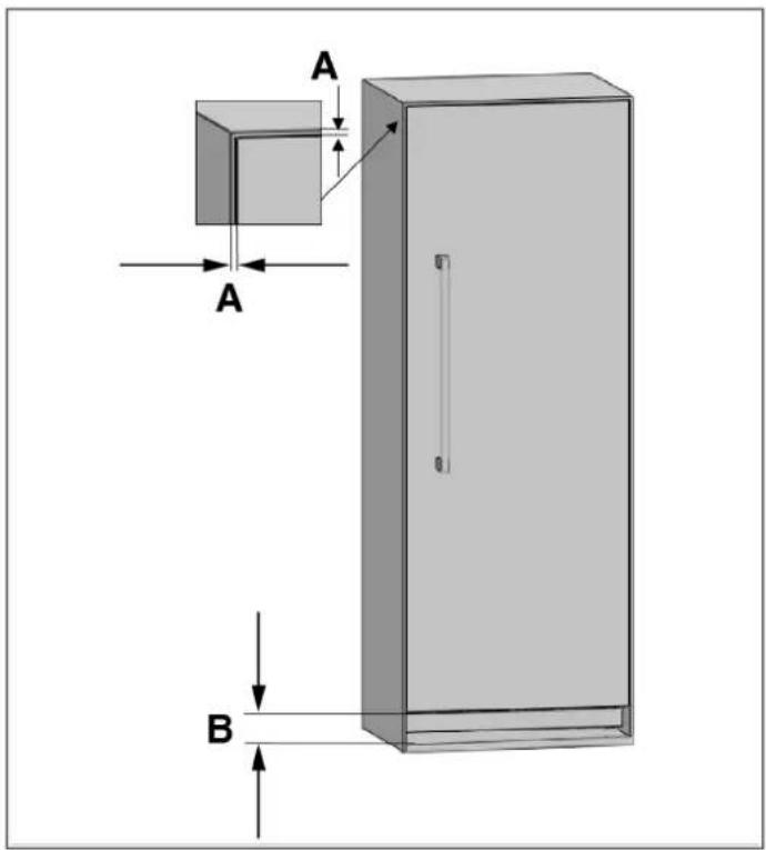
Fig. 28
A 3 mm (1/8")
B 102 mm (4")
Adjusting the height of the refrigerator within the niche.
- Use the adjustable leg mechanism to raise, lower and level the unit in the niche as per the diagram below.

WARNING
Once the unit is pushed into the niche, raise the front feet first; this will reduce the risk of the unit tipping forward during the height adjustment process.
The maximum height that the adjustable feet can reach is 40 mm (1 9/16").
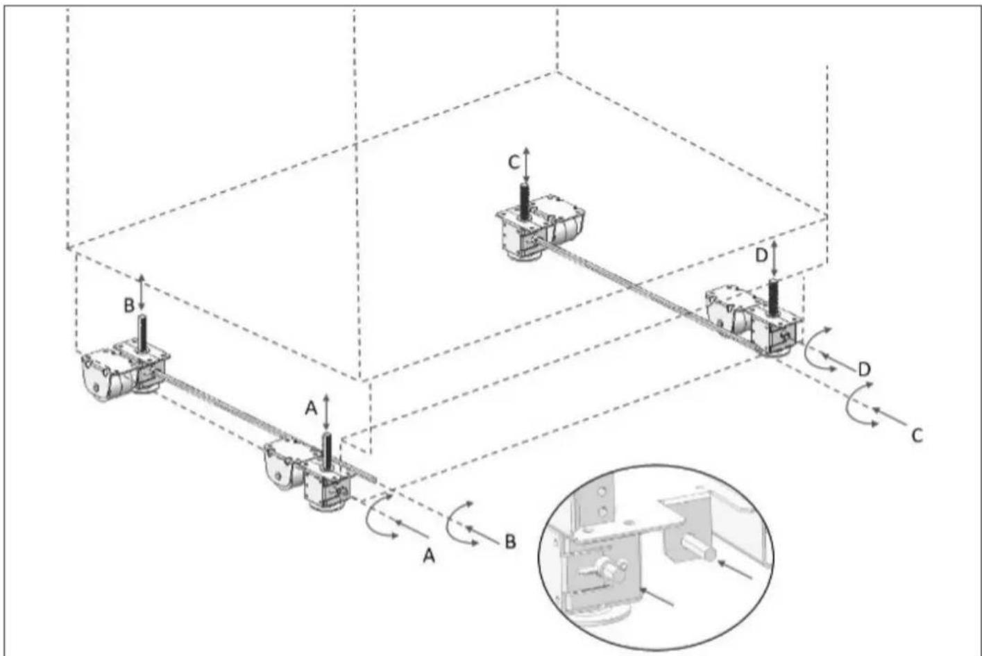
Fig. 29
A/D –Turn the adjusting rod clockwise to lift the front
B/C –Turn the adjusting rod clockwise to lift the rear
For each 360 degree rotation, the legs are raised 1.5 mm (1/16").
We recommend raising the front legs by 8 mm (5/16") and the rear legs by 7 mm (9/32"): rotate the front feet 5.5 times and the rear feet 4.5 times.
natural_image
Interior view of a server rack unit with open door, internal compartments, and visible wiring (no text or symbols)Fig. 30
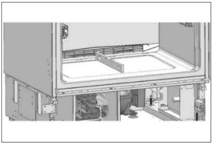
• After adjusting the adjustable feet, check that the appliance is level both side-to-side and back-to-front by placing a level on the floor of the freezer compartment (the drawer should be removed for this).
Adjusting the refrigerator based on the cabinet niche.
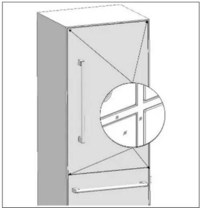
- For products with supplied stainless steel panel doors, the position of the unit is adjusted so that the door and the cabinet surface are flush and a min. 3,2 mm (1/8") distance from panels and gables is ensured.
natural_image
Technical line drawing of a cabinet with internal components and a magnified inset showing window frame detail (no text or symbols)Fig. 31
- For panel-ready units, the refrigerator should be installed at a depth that takes into consideration the custom overlay panel thickness, so as to ensure a flush installation, if desired.

NOTE
It is important to align the upper edge of the freezer drawer when aligning the unit, as its height and position are fixed. All of the other panels can be adjusted using the adjustment mechanisms built into the mounting hardware. As shown below, an installation depth template tool is provided for your convenience.
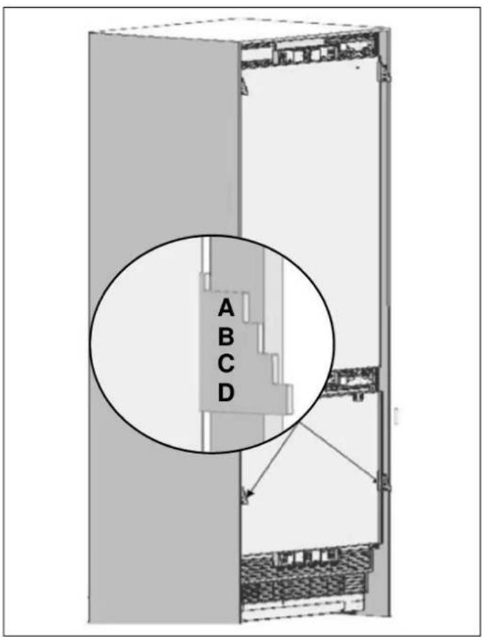
Fig. 32
A 19 mm (3/4")
B 24 mm (15/16")
C 32 mm (1 1/4")
D 38 mm (1 1/2")
A 3/4"(19 mm)
B 15/16" (24 mm)
C 1 1/4" (32 mm)
D 1 1/2" (38 mm)
- The position of the level adjustment part (#3) must be adjusted based on the thickness of the door. It can adjust the level for 4 different door thicknesses.
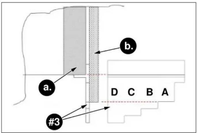
Fig. 33
a. Refrigerator
b. Cabinet side panel
A 19 mm (3/4")
B 24 mm (15/16")
C 32 mm (1 1/4")
D 38 mm (1 1/2")

NOTE
The niche must be designed to accommodate the minimum depth requirement plus the thicker door panel, if desired. Regardless of door thickness, the maximum panel weights must always be respected, or the product warranty will be void.
SCREWING IN THE SIDE BRACKETS
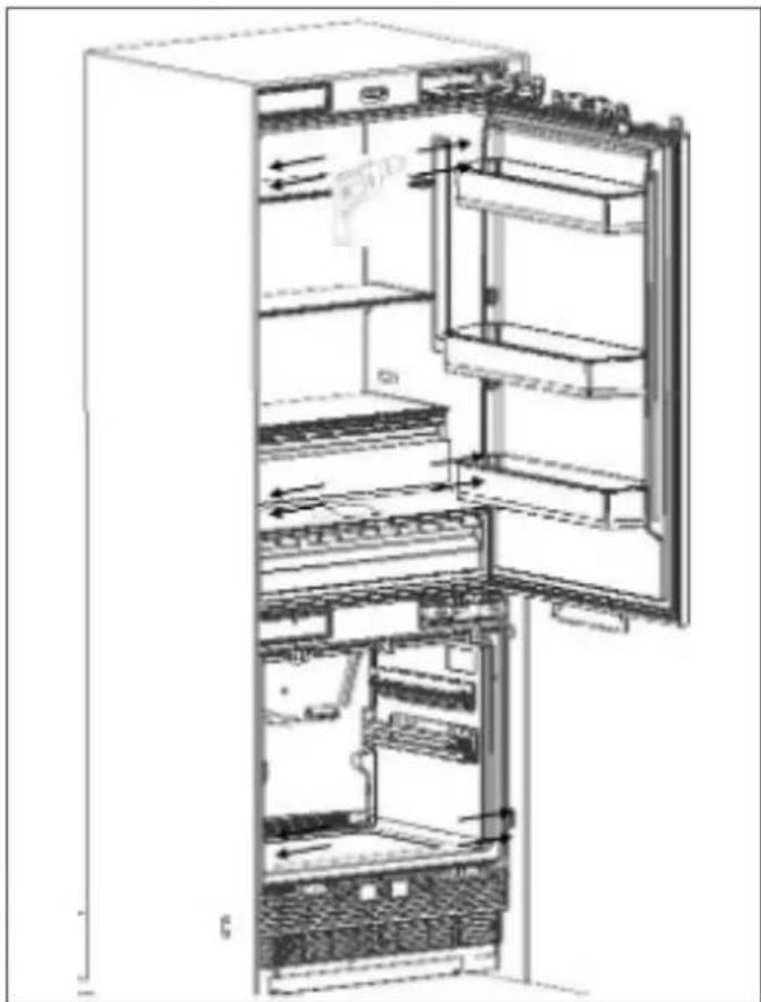
- Mount the brackets (#12) on the unit, with 2 on the top and 3 on each side. Use screws (#14) to tighten them in place.
• Use 12 long screws (#13) to join the unit to the cabinet.

WARNING
Before screwing the side brackets into the cabinet gables, ensure the screw is shorter than the gable thickness, otherwise the finished side may be damaged.
Before beginning to screw on the side and upper brackets, make sure that the unit is connected to power, that water (if applicable) is being supplied to the appliance and that the water connection has been tested for leaks.
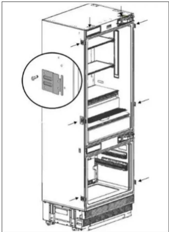
natural_image
Technical line drawing of a refrigerator internal structure with an inset showing a close-up of the door panel (no text or symbols present)Fig. 34

NOTE
Drilling a pilot hole in the side gable for reference could make the mounting process easier.
natural_image
Interior view of a refrigerator showing open doors, shelves, and internal compartments (no text or labels visible)SECURING THE UPPER BRACKET
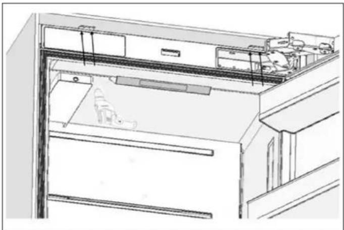
- Attach the upper bracket to the cabinet using 4 screws (#13).

NOTE
Drilling a pilot hole in the side gable for reference could make the mounting process easier.
natural_image
Line drawing of a cabinet interior showing front and side views (no text or symbols)Fig. 36
Fig. 35
INSTALLING THE BOTTOM CABINET
Complete the water connection
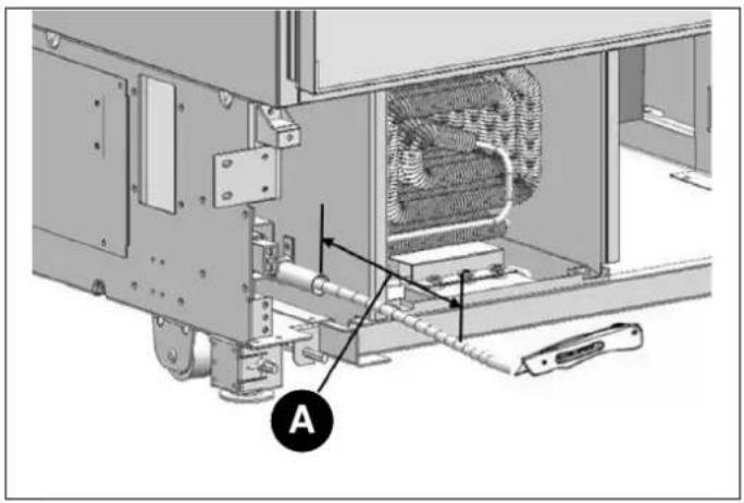
- Use a cutter to cut of any excess waterline length, allowing sufficient slack of 254 mm (10") to ensure an easy bend and clear connection, with no tension or potential kinks in the supply line that runs to the connector.
natural_image
Technical diagram of an industrial machine with labeled component A, showing internal components and wiring (no readable text or symbols)Fig. 37
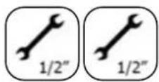
- A 254 mm (10") - Use 2 wrenches to firmly connect both the hose that runs from the mains and the connection to the valve on the refrigerator.

WARNING
The hose that runs from the mains connection must be one piece. Do not use extension hoses.

WARNING
Make sure that the power is cut off when establishing the appliance's water connection.

WARNING
The water valve must be closed when connecting the water hose.

WARNING
It is recommended to keep the water valve accessible after product installation.

WARNING
The pressure of the water system must be between 1.7-5.5 bar (25-80 psi).

NOTE
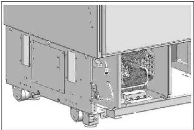
Once the connection is complete, you must open the water valve and make sure that there is no leakage.
natural_image
Technical line drawing of an industrial machine with visible internal components and mounting brackets (no text or symbols)Fig. 38
ATTACHING THE AIR VENT GRILLE
- Use 5 screws to attach the vent aperture component.
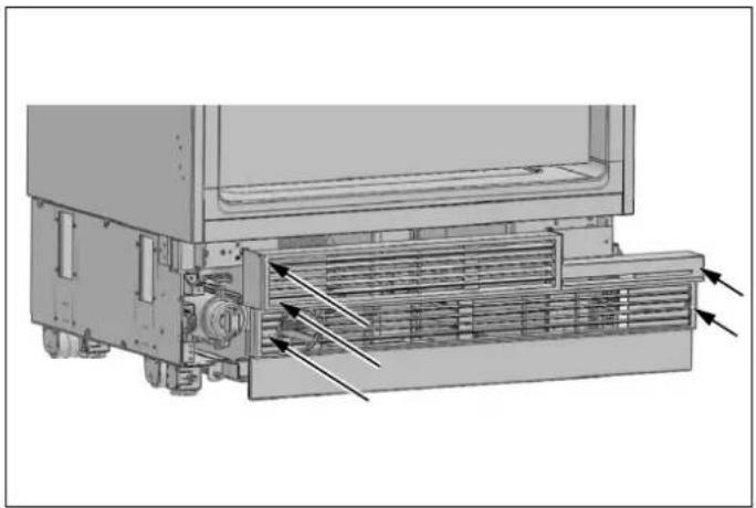
natural_image
Technical diagram of a mechanical device with internal components and directional arrows indicating flow or movement (no text or symbols present)Fig. 39
ATTACHING THE DECORATIVE TRIM COVERS
- The decorative side trim is a soft plastic material with a barbed end intended to be inserted between the cabinet gable and the appliance body (#2), onto the right/left connection brackets. Some trimming may be required to ensure the trim pieces can fit around the brackets; the thickness of the barbed end may also require trimming depending on the width of the gap between the side body and the cabinet gable.
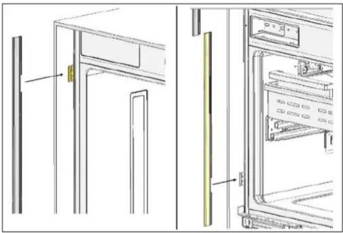
natural_image
Technical line drawing of a door panel and refrigerator interior (no text or symbols)Fig. 40

NOTE
The lower grill can be adjusted forward or backward of 24 mm (15/16") to accommodate the cabinet toe kick. Also, a piece of decorative cabinet toe kick material can be affixed to the lower grill to match the cabinets, provided there is no obstruction to vent grills and air flow.

WARNING
If installing a one-piece cabinet toe kick across the front of the fridge, you must ensure proper air flow and no obstruction to the vent grills.
- Push in the finished trim (#1) on the upper connection bracket.
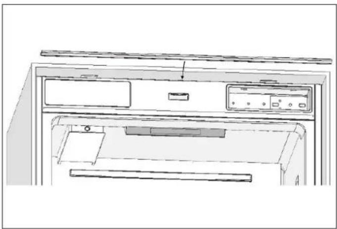
natural_image
Line drawing of a computer monitor with an open lid and drive bays (no text or symbols)Fig. 41
OVERLAY PANEL INSTALLATION AND PREPARATION
This section contains information about preparing the cabinet doors and mounting them on the product.

WARNING
Maximum weights of the panels to be mounted on the unit are as follows:
• Refrigerator Column Door: 30 kg (66 lbs)
• Freezer Column Door: 30 kg (66 lbs)
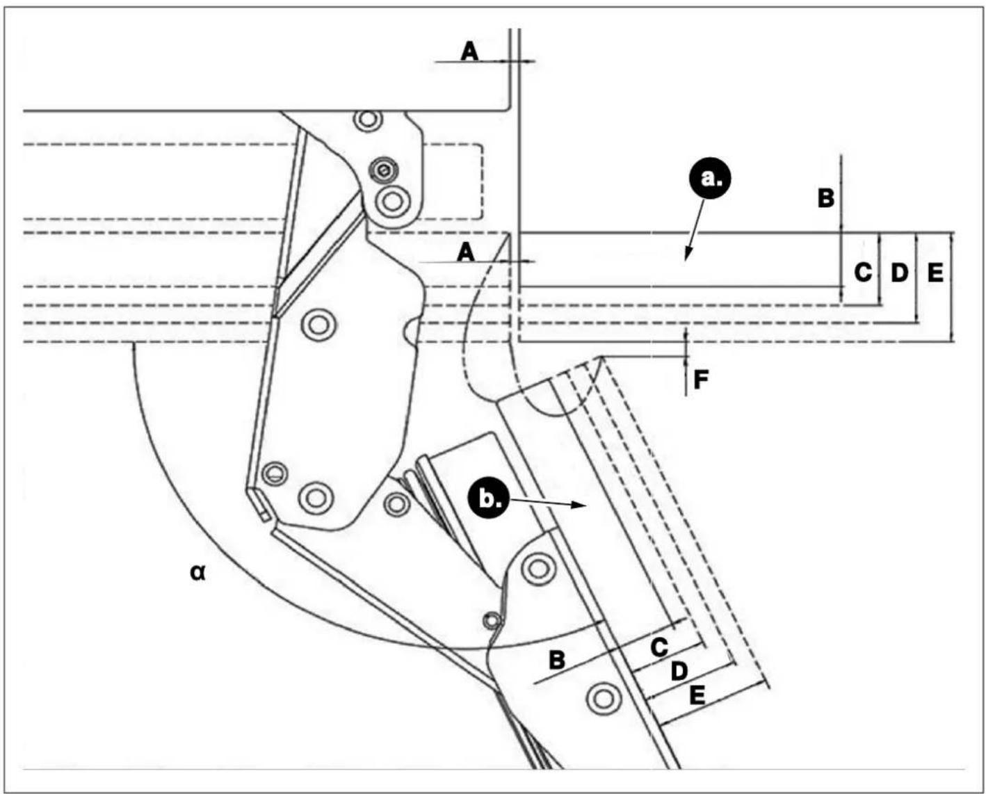
Fig. 42
a. Cabinet front
b. Front panel
A. 3 mm (1/8")
B. 19 mm (3/4")
C. 24 mm (15/16")
D. 32 mm (1 1/4")
E. 38 mm (1 1/2")
F. 5 mm (3/16")
θ. 115°
CHOOSING THE DOOR THICKNESS
- The door of your refrigerator can open to 115° maximum. If you want the doors to open to this degree, you can choose from the thicknesses shown in the image above.

WARNING
If the door thickness is more than 38 mm (1 1/2"), the door should not open more than 90°. You must use a limiting pin on the hinge.
A limiting pin (#17) is provided with the unit to prevent the door from opening beyond 90° if necessary; it can be installed on the hinge. Door thickness allowances when using the limiting pin are shown in the diagram below.
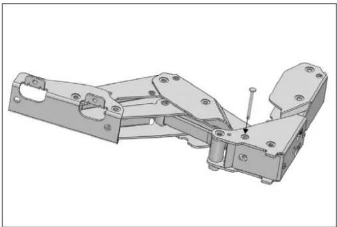
natural_image
3D mechanical assembly diagram showing a bracket with mounting holes and a small pin (no text or symbols)Fig. 43
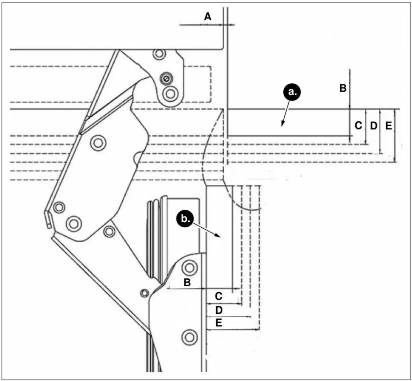
Fig. 44
a. Cabinet front
b. Front panel
A. 3 mm (1/8")
B. 19 mm (3/4")
C. 24 mm (15/16")
D. 32 mm (1 1/4")
E. 38 mm (1 1/2")
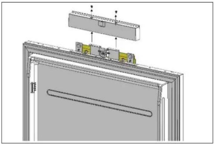
REMOVING THE OVERLAY PANEL MECHANISM COVERS
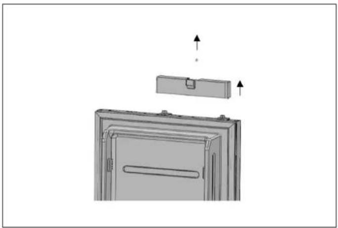
- Remove the upper screws to remove the upper cover.
natural_image
Technical diagram of a door frame assembly with mounting brackets and internal components (no text or symbols)- Remove the two screws to remove the door hanging bracket for the lower mechanism cover.
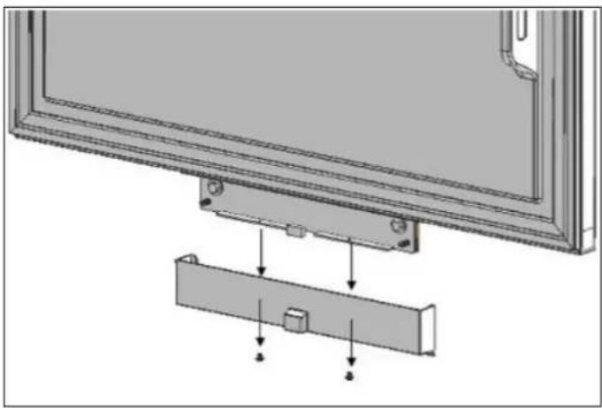
natural_image
Technical diagram showing a mounted device with mounting brackets and a separate panel, no text or symbols presentFig. 47
Fig. 45 RFZ45S5FPRS / RFZ45S5FPLS RFZ60S5FPNS RLD60S5FPNS
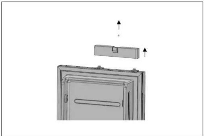
natural_image
Diagram of a refrigerator interior showing front panel, door, and side shelf with upward arrows indicating movement (no text or symbols)Fig. 46 RLD75S5FPNS

WARNING
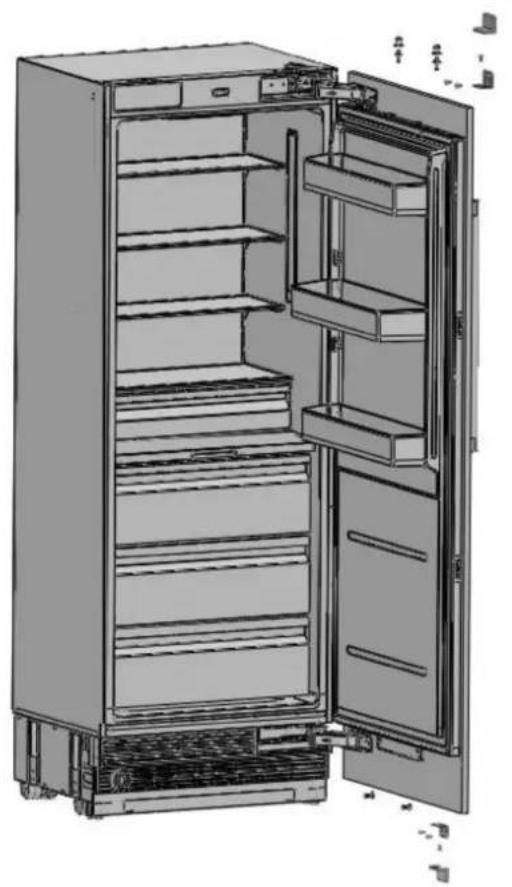
There is a magnet on the upper cover of the door hanging bracket. This is a functional component for product operation, because it activates the door open reed switch. Please ensure the covers do not get switched; put each back on the same bracket it was removed from. Do not exchange the lower cover with the upper cover. The magnet must remain in the upper part.
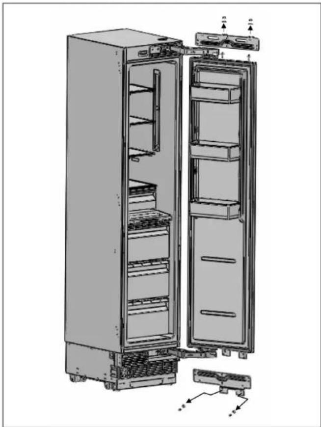
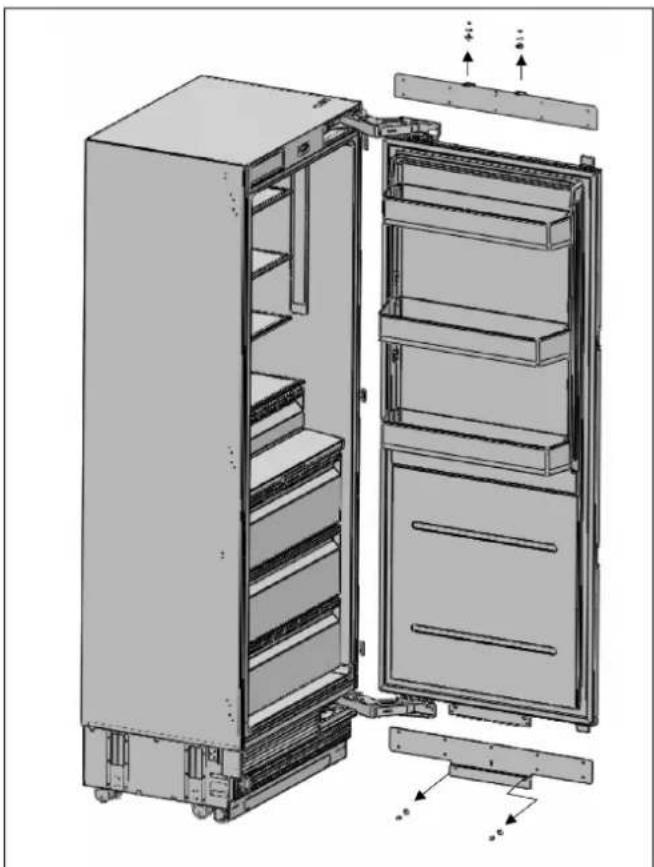
REMOVING THE PANEL BRACKETS
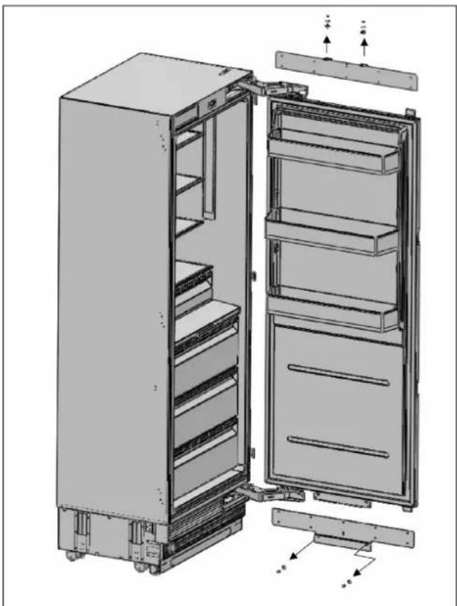
- Remove the upper and lower adjustable panel mounting brackets from the door panel adjustment mechanisms, as shown below.
natural_image
Exploded view diagram of an open refrigerator showing internal compartments and doorways (no text or labels)Fig. 48 RFZ45S5FPRS / RFZ45S5FPLS
natural_image
Technical illustration of an open refrigerator with visible door, shelves, and cooling unit (no text or labels)Fig. 49 RFZ60S5FPNS RLD60S5FPNS RLD75S5FPNS
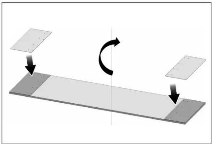
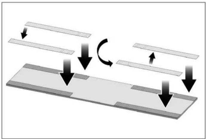
PREPARING THE OVERLAY PANELS

NOTE
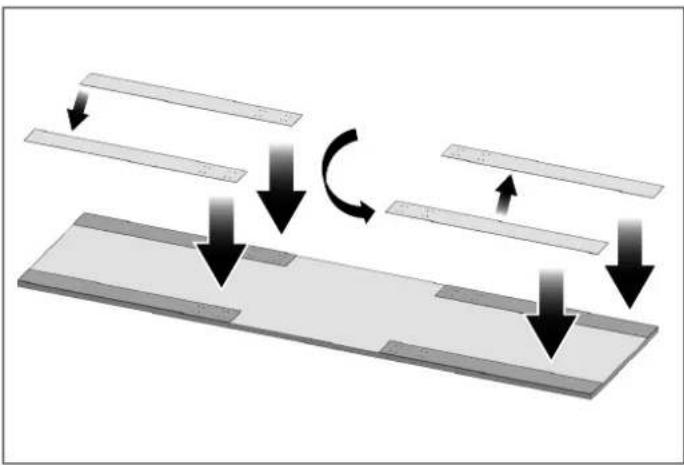
When marking, you can use the door/ drawer panel preparation template provided with the product.
natural_image
Diagram showing a rotating mechanical component with two plates and directional arrows indicating rotation (no text or symbols)Fig. 50
natural_image
Diagram showing a mechanical or structural assembly with multiple downward arrows indicating motion or force, no text or symbols present.Fig. 51
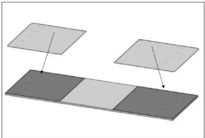
natural_image
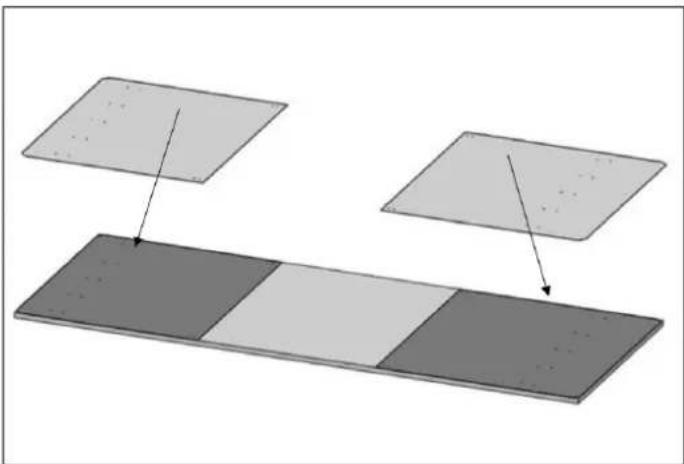
Diagram showing two rectangular panels with different shades of gray, one above a dark panel and the other below (no text or symbols)Fig. 52

WARNING
The handle mounting holes will have to be adjusted based on the handles to be used in the kitchen design.

WARNING
The minimum door thickness must be 19 mm (3/4").
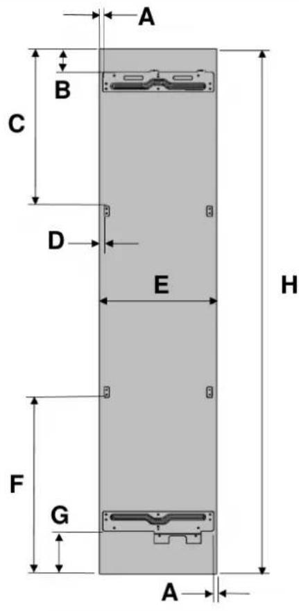
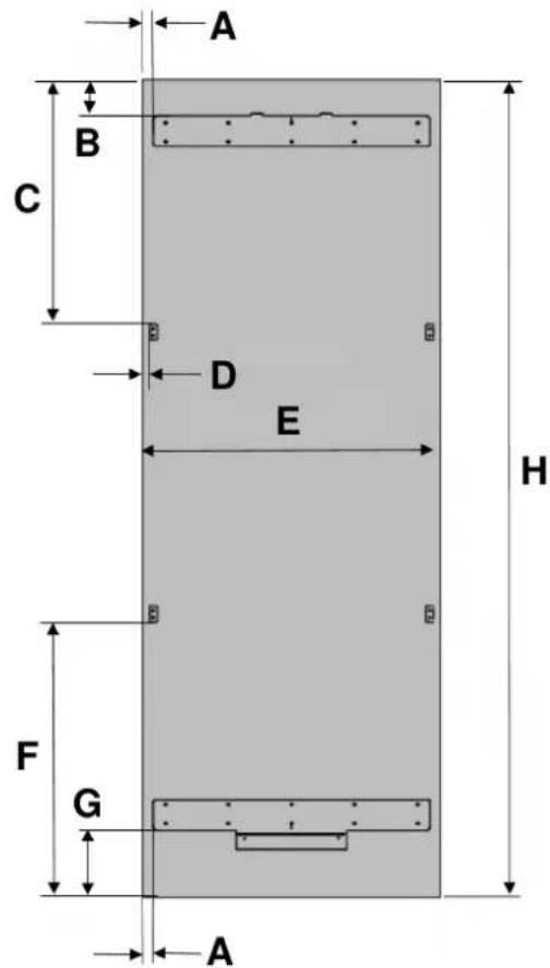
Fig. 53 RFZ45S5FPRS / RFZ45S5FPLS Fig. 54 RFZ60S5FPNS RLD60S5FPNS RLD75S5FPNS
| CATEGORY | RFZ45S5FPRS / RFZ45S5FPLS | RFZ60S5FPNS RLD60S5FPNS RLD75S5FPNS |
| A | 10 mm (3/8") 10 mm (3/8") 10 mm (3/8") 10 mm (3/8") | |
| B | 85 mm (3 3/8") | |
| C | 595.5 mm (23 7/16") | |
| D | 18.2 mm (7/10") | |
| E | 451 mm (17 3/4") 603 mm (23 3/4") 603 mm (23 3/4") 756 mm (29 3/4") | |
| F | 693.5 mm (27 5/16") | |
| G | 175 mm (6 7/8") | |
| H | 2030 mm (79 15/16") | |

WARNING
• To prevent damage to the finished surface of the panel, use screws suitable for the door panel thickness.
Install the panel brackets using screws (#15). You can also use the template (#6) provided with the product to align these parts. It is recommended to keep this template for future reference.
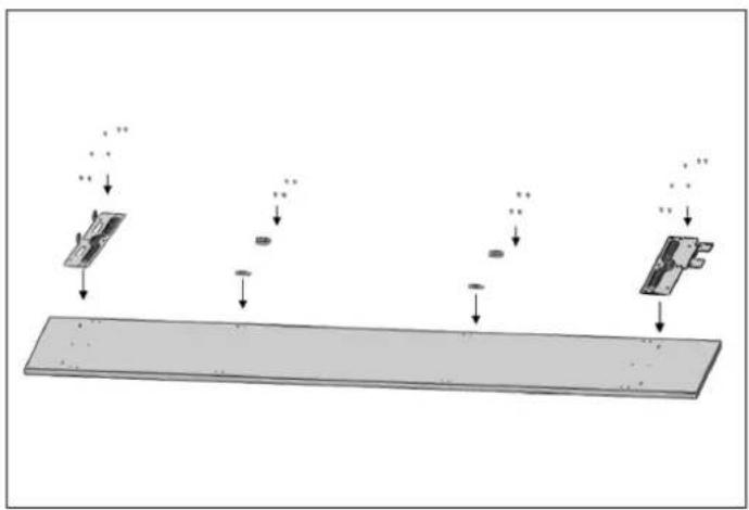
flowchart
graph TD
    A["Input"] --> B["Process Unit"]
    C["Input"] --> D["Process Unit"]
    E["Input"] --> F["Output"]
    G["Input"] --> H["Output"]
Fig. 55 RFZ45S5FPRS / RFZ45S5FPLS
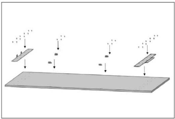
Fig. 56 RFZ60S5FPNS RLD60S5FPNS RLD75S5FPNS
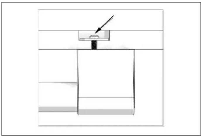
Attach the door handle to the upper door panel prior to installing the panel on the fridge. Use handle hardware that will ensure a secure connection to the panel and that will lie flush against or, in any case, not protrude from the back of the overlay panel. This may require countersinking the handle hardware into the back of the panel, as shown below. The door handle mounting screws must not protrude either.
natural_image
Simple line drawing of a mechanical setup with a piston and lever, no text or symbols presentFig. 57 RFZ45S5FPRS / RFZ45S5FPLS

WARNING
The handle mounting holes will have to be adjusted based on the handles to be used in the kitchen design.

WARNING
The minimum door thickness must be 19 mm (3/4").

WARNING
To prevent damage to the finished surface of the panel, use screws suitable for the door thickness.
INSTALLING THE OVERLAY PANELS
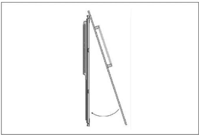
- Attach the furniture door to the door
natural_image
Pure technical line drawing of a mechanical component or bracket assembly without any text, numbers, or symbolsFig. 58
ALIGNING THE UPPER PART OF THE CUSTOM DOOR ALIGNING THE LOWER PART OF THE CUSTOM DOOR PANEL WITH BOLTS PANEL WITH BOLTS.
- The custom panel for the refrigerator must be flush with the cabinet doors beside it.
To achieve this, it is necessary to adjust the 3D direction using two fixing bolts.
First, check the position of the refrigerator door in relation to the kitchen cabinets.
The distance between the door and the cabinets beside it should be 3 mm (1/8"), assuming that the door dimensions are correct.
You can now adjust the door according to this distance.
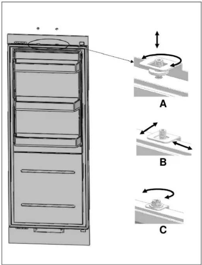
Fig. 59 RFZ60S5FPNS RLD60S5FPNS RLD75S5FPNS
A Up & Down
B Front & back / Left & right
C Fixing furniture door completely

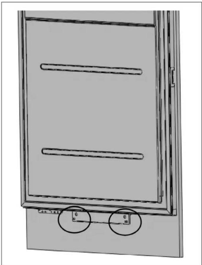
natural_image
Technical line drawing of a door frame with two horizontal bars and two circular annotations indicating measurement points (no text or symbols present)Fig. 60
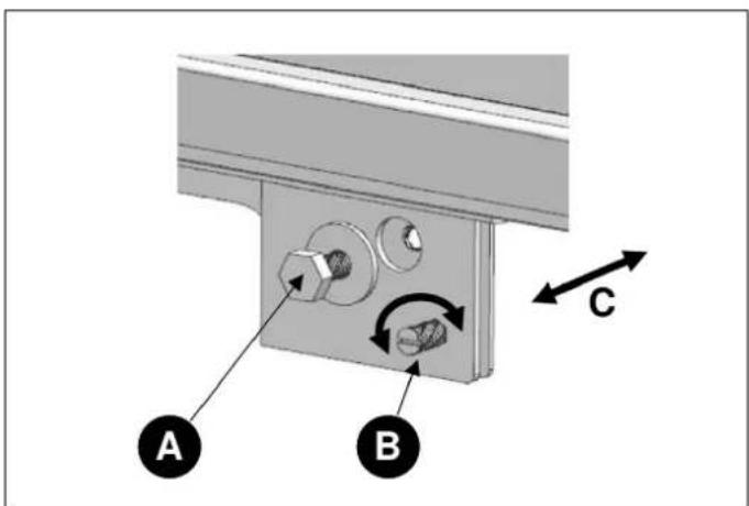
Fig. 61
A Up & Down
B Fixing furniture door completely
C Front & back
- Use the bracket furniture door (Item No6) to join the furniture door
• Use 2 screws (Item No7) and 1 screw (Item No5) to fix.
natural_image
Three icons: a pencil, a wrench, and a hammer, each enclosed in rounded squares (no text or symbols)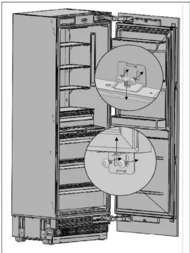
natural_image
Interior view of a refrigerator showing open doors and internal components with circular insets (no text or symbols)Fig. 62 RFZ60S5FPNS RLD60S5FPNS RLD75S5FPNS
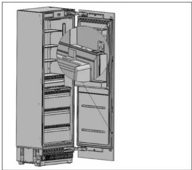
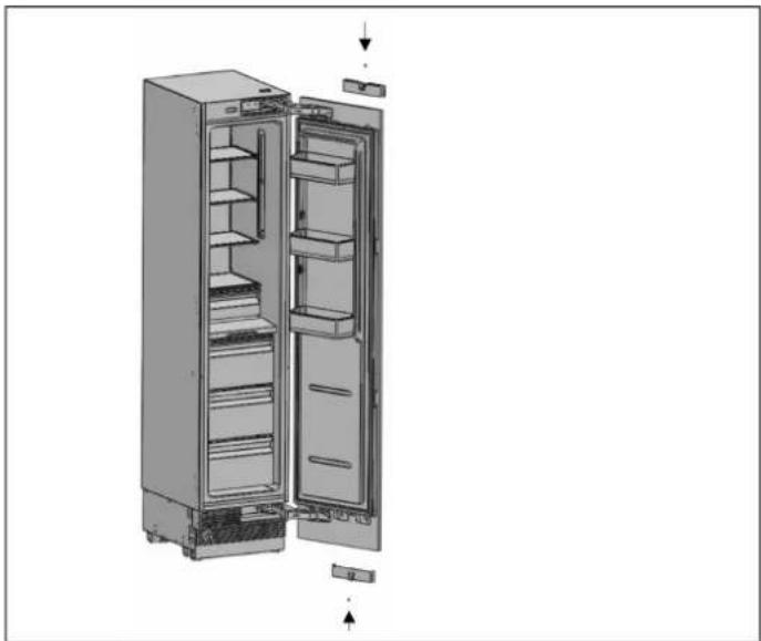
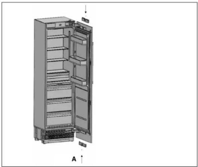
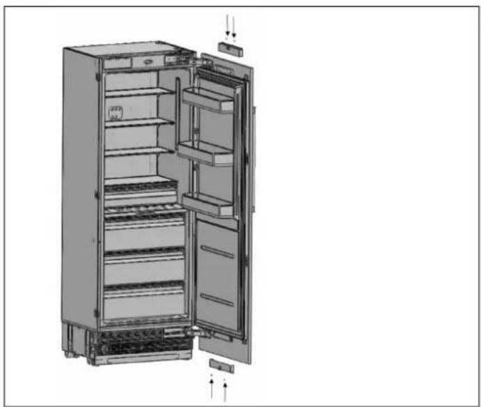
- Clip the cover furniture door bracket.
- Attach and screw the upper/lower decoration covers.
natural_image
Interior view of a refrigerator showing open doors, shelves, and a close-up of the door (no text or symbols visible)Fig. 63 RFZ60S5FPNS RLD60S5FPNS
RLD75S5FPNS
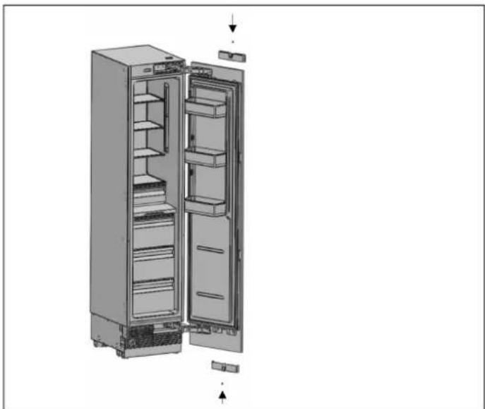
natural_image
Exploded view diagram of an open refrigerator showing internal compartments and doorways (no text or labels)Fig. 64 RFZ45S5FPRS / RFZ45S5FPLS
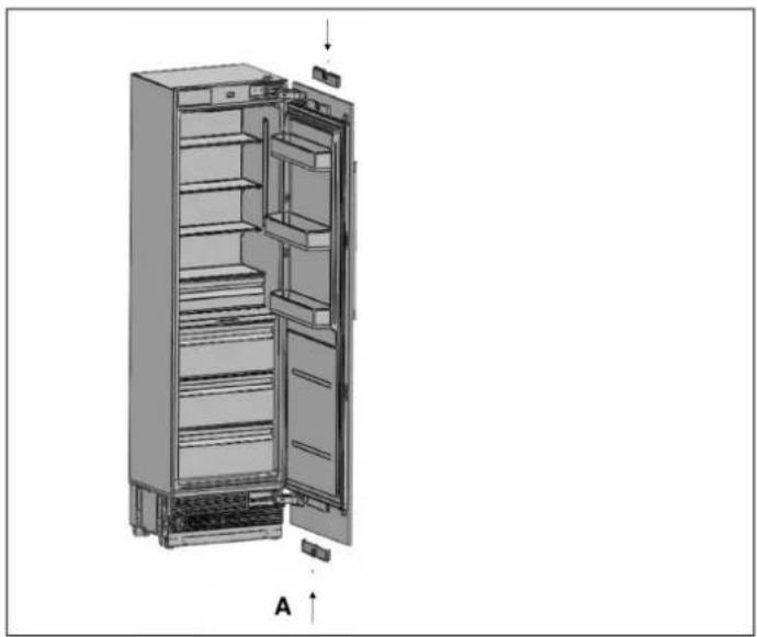
natural_image
3D diagram of a refrigerator interior showing internal compartments and doorways (no text or labels)Fig. 65 RFZ60S5FPNS RLD60S5FPNS
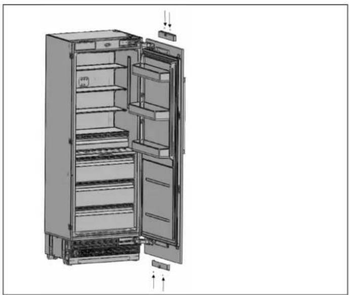
natural_image
Technical illustration of an open refrigerator with visible door, shelves, and cooling unit (no text or labels)Fig. 66 RLD75S5FPNS
After the top and bottom door panel brackets are secured by installing screws, use screw (Item No8) and square washer (Item No9) to secure the center mounting bracket.
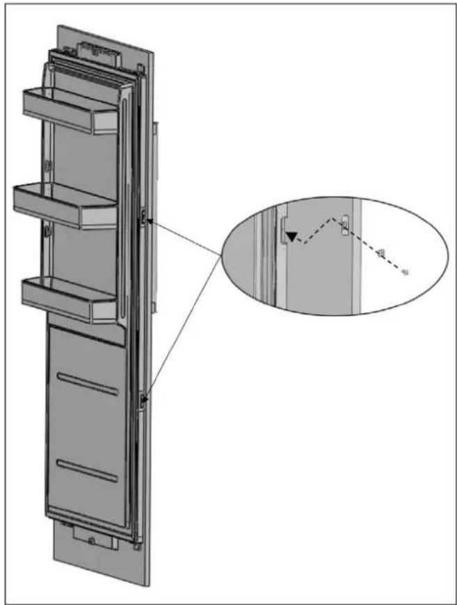
natural_image
Technical line drawing of a multi-panel refrigerator with an inset close-up showing a dashed line indicating alignment or adjustment (no text or symbols present)Fig. 67

WARNING
You must keep these parts for future use.
You will need them if you want to change the door directions.
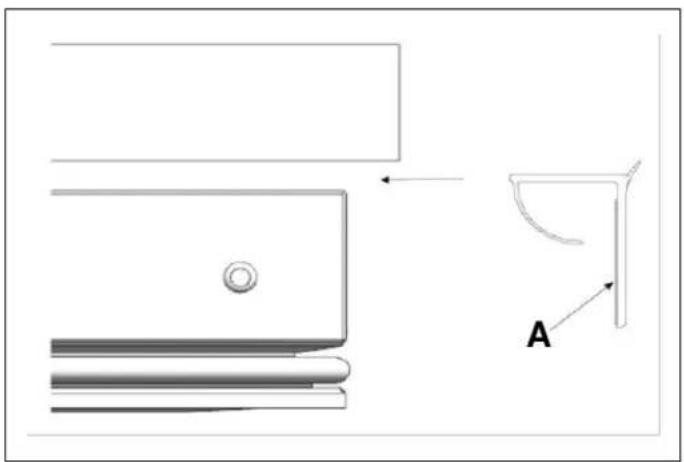
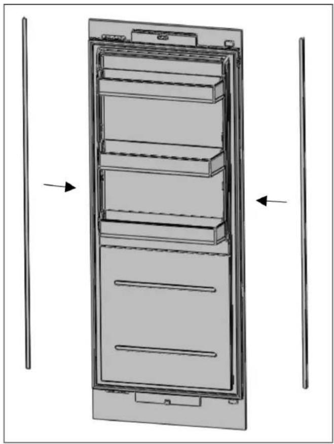
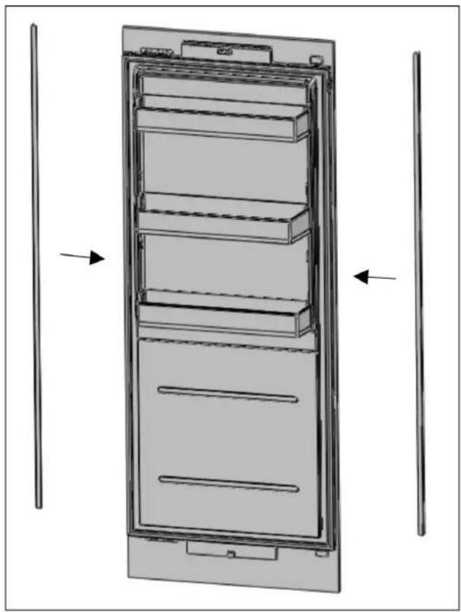
- Attach the Trim door side (Item No3)
natural_image
Technical line drawing of a mechanical component with labeled section A (no text or symbols beyond label)Fig. 68
A Tape double
natural_image
Technical line drawing of a multi-tiered refrigerator with two vertical supports and an arrow indicating direction (no text or symbols)Fig. 69
HINGE ADJUSTMENT AND REVERSING THE DOOR SWING
ADJUSTING THE SPRING TENSION OF THE HINGES
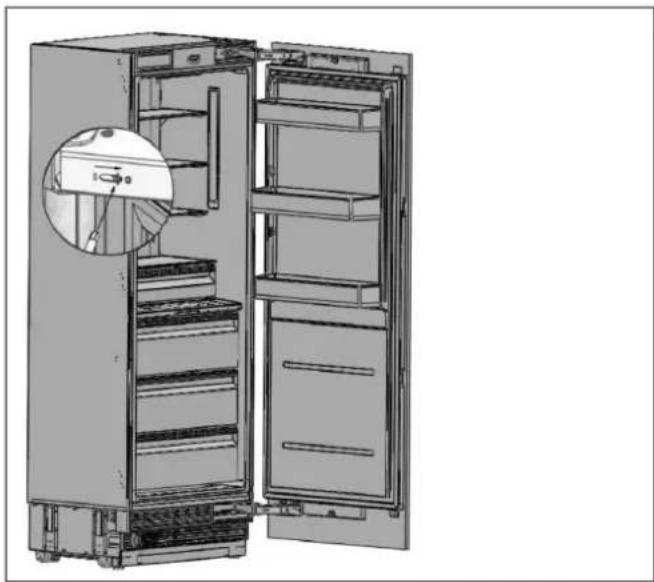
- Use a drill to adjust the tension of the upper and lower hinges of the fridge door. Set the hinge adjustment screw to position "I" from position "O".

natural_image
Technical illustration of an open refrigerator with a close-up inset showing internal components (no text or symbols)Fig. 70

WARNING
The door must be fully open during this adjustment.

WARNING
The hinge tension adjustment must be performed only after the door panel has been adjusted.
REMOVING THE DOOR PANEL
- Set the tension level of the hinge to "0".
natural_image
Technical line drawing of an open refrigerator with a circular inset showing the interior portion (no text or symbols)Fig. 71

CAUTION
Failure to set the hinge to "0" before continuing the installation may result in injury.
- Remove the side closing seals.
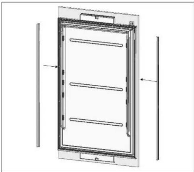
natural_image
Technical line drawing of a door frame with two vertical supports and horizontal bars, no text or symbols presentFig. 72
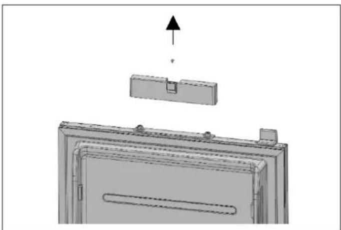
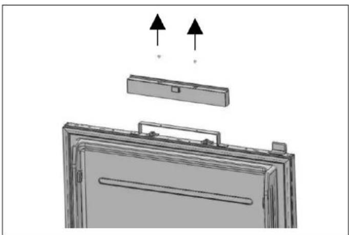
- Loosen the 2 screws in the upper cover of the fridge door and remove it.
• Take out the upper adjustment kits.
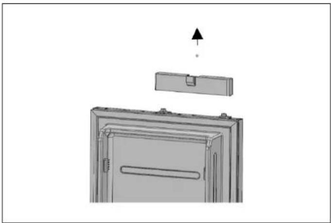
natural_image
Diagram of a door with an open lid and a handle, showing a mechanical assembly (no text or symbols)Fig. 73 RFZ45S5FPRS / RFZ45S5FPLS
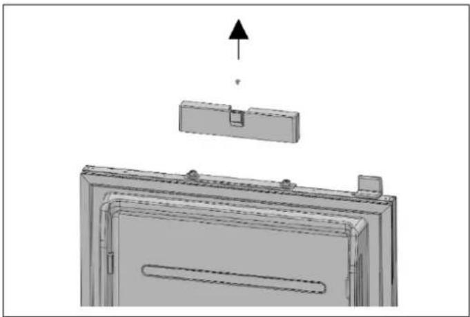
natural_image
3D technical diagram of a mechanical assembly with an upward arrow indicating force or direction (no text or symbols present)Fig. 74 RFZ60S5FPNS RLD60S5FPNS
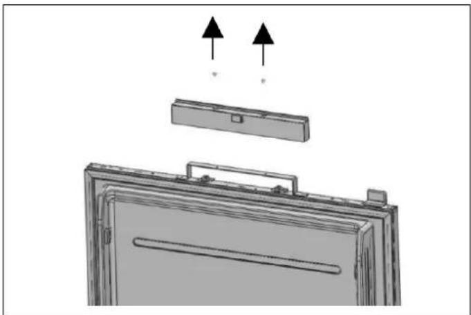
natural_image
Diagram of a device with two arrows pointing to a component, showing internal structure and mounting points (no text or symbols)Fig. 75 RLD75S5FPNS
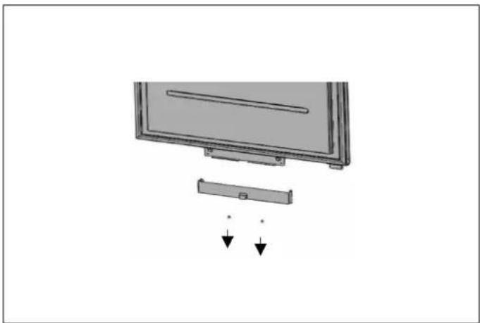
- Loosen the 2 screws in the upper cover of the fridge door and remove it.
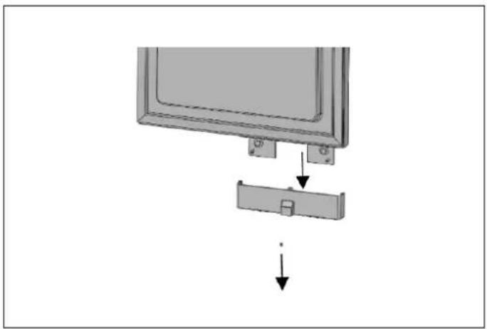
natural_image
Diagram showing a monitor with a close-up of its side panel and a separate clip, connected by arrows indicating assembly or disassembly (no text or symbols present)Fig. 76 RFZ45S5FPRS / RFZ45S5FPLS
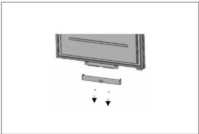
natural_image
Diagram of a monitor with an attached cable and two arrows indicating downward motion (no text or symbols)Fig. 78 RLD75S5FPNS
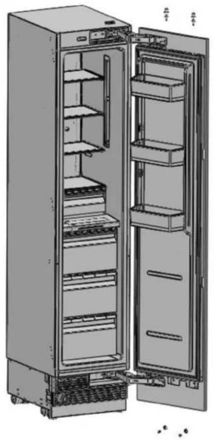
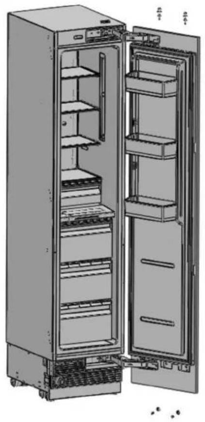
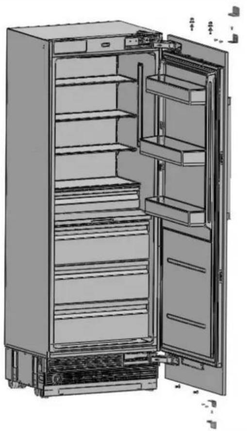
Remove the lower and upper bracket screws from the fridge.
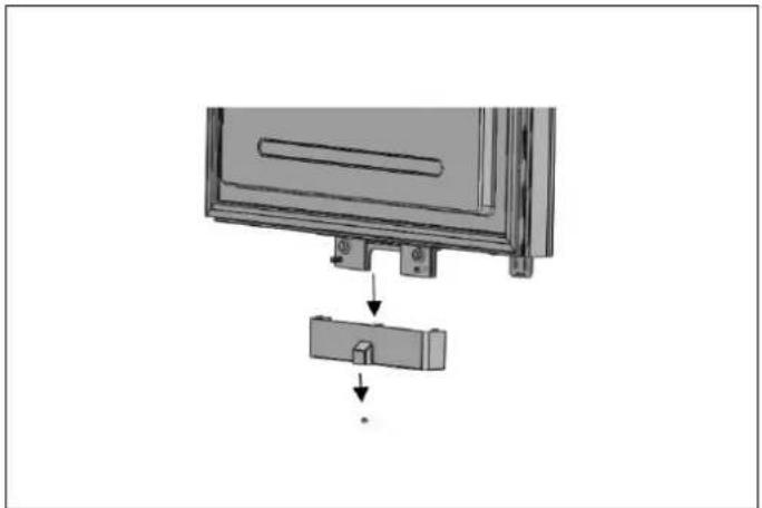
natural_image
Diagram showing a device with a lock and a separate component, no text or symbols presentFig. 77 RFZ60S5FPNS RLD60S5FPNS
natural_image
Interior view of a refrigerator with open doors and shelves (no text or symbols visible)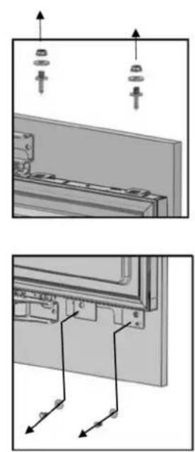
natural_image
Technical diagram showing two views of a mechanical assembly with arrows indicating direction (no text or symbols present)Fig. 79 RFZ45S5FPRS / RFZ45S5FPLS
natural_image
Interior view of a fully stocked refrigerator with open doors and shelves (no text or symbols visible)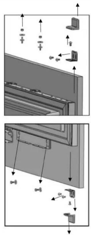
Fig. 80 RFZ60S5FPNS RLD60S5FPNS RLD75S5FPNS
- Remove the screw from the upper and from the lower fridge mechanism.

WARNING
The fridge door panel will be released when these screws are removed. You must take measures to prevent the door from falling.
You can tape the cabinet door to the inner door or ask a second person to help.
• Take off the fridge cabinet door and lay it upside down on a table top.
- You must attach the cabinet door by rotating it 180^ with respect to its current position.
REMOVING AND PREPARING THE INNER DOOR
- Remove the hinge connection screws from the hinge brackets.

CAUTION
The door will be released when these screws are removed. You must take measures to prevent the door from falling. You can tape the cabinet door to the inner door or ask a second person to help.
natural_image
Technical diagram of an open electrical cabinet with internal components and a magnified inset showing internal wiring (no text or symbols present)Fig. 81
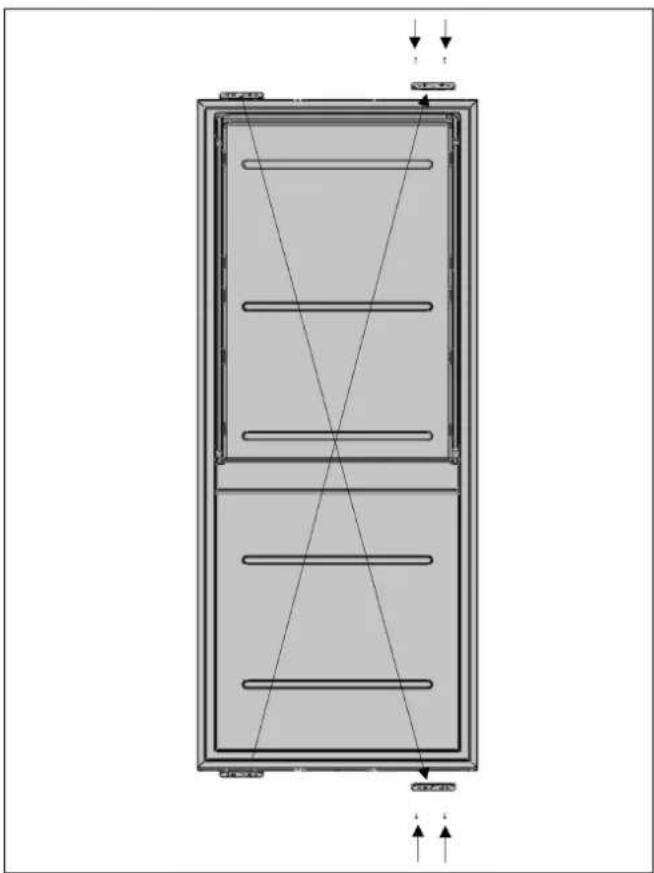
Take off the fridge door and lay it on a table top, then remove the mounting components and screw them to the opposite side of the door.
- Use 2 screws to attach the door hanging bracket.
natural_image
Technical line drawing of a vertical cabinet or enclosure with horizontal ribs and diagonal braces, no text or symbols present.Fig. 82
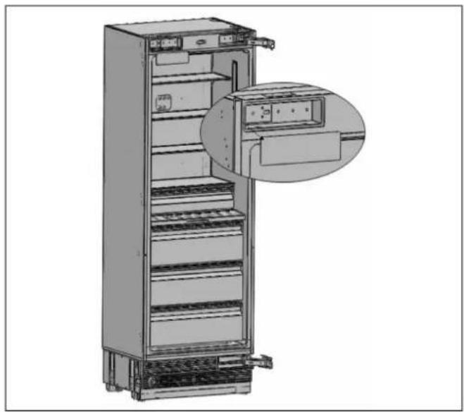
REPLACING THE HINGES
- Remove the Hinge Caps located at the other side where you will fix the hinges.
natural_image
Illustration of a multi-tiered refrigerator with an inset close-up showing the interior panel (no text or symbols visible)Fig. 83
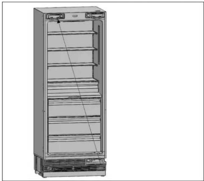
- Remove the lower right hinge by loosening its 2 screws and fix it to its slot at the upper left side.

natural_image
Line drawing of a multi-tier refrigerator cabinet with open doors and internal shelves (no text or symbols)Fig. 84
AIR VENT UPPER PART DIRECTION CHANGE
- Remove the air vent part and change direction as shown in the figure.
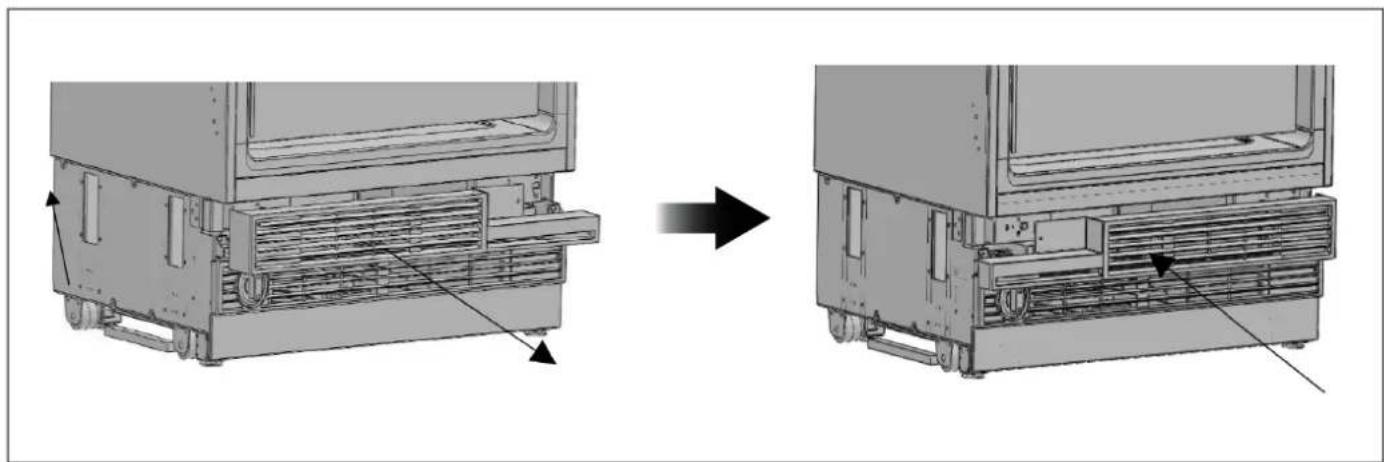
natural_image
Technical illustration of a mechanical device showing front and side views of internal components (no text or symbols)Fig. 85
HOW TO CHANGE AIR VENT UPPER PART DIRECTION
• Air vent upper part for the right hinge
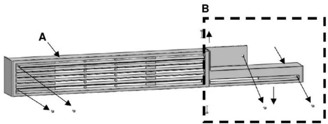
Fig. 86
A Air vent cover
• B Air vent hinge part right
• Air vent upper part for the left hinge

Fig. 87
• C Air vent hinge part left
• D Rotate air vent cover by 180°
- Remove the upper right hinge by loosening its 2 screws and fix it to its slot at the lower left side.
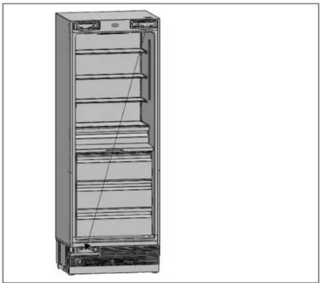
natural_image
3D line drawing of a refrigerator cabinet with shelves and doors (no text or symbols)Fig. 88
- Attach the Hinge Slot Caps removed from the left side to the Hinge Caps to the right side.
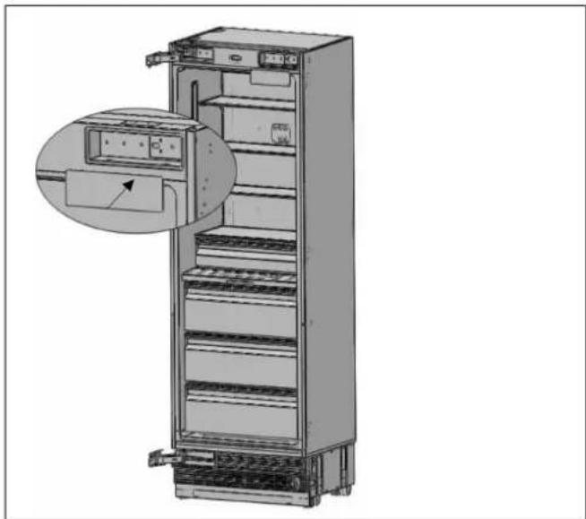
natural_image
Diagram of a refrigerator interior showing the exterior and front views, with one door open and an arrow indicating a component (no text or symbols present)Fig. 89
REINSTALLING THE DOOR
Place the inner door on the refrigerator using the door seal to help hold the door in place and fasten it back onto the hinges using 4 screws.

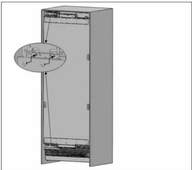
natural_image
Technical diagram of an open refrigerator with internal components and a magnified inset showing internal wiring (no text or symbols)Fig. 90
- All freezer columns include one connection trim kit (CTXV).
CABINET CUTOUT DIMENSIONS
Please check cabinet cutout dimensions below before starting the installation.
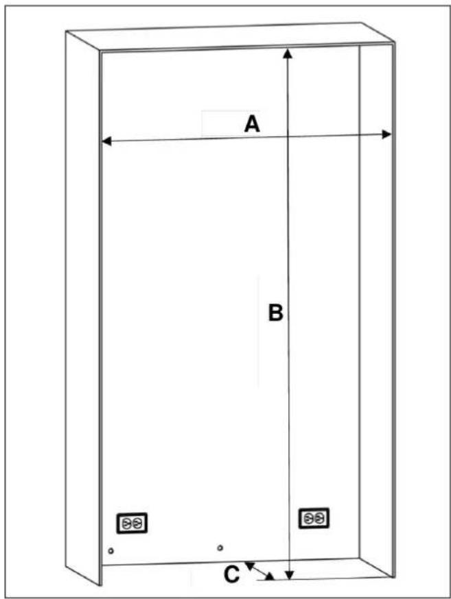
Fig. 91
CONFIGURATION A B C
| 45+60 cm (18"+24") 1066 mm (42") 2134 mm (84") 635 mm (25") |
| 45+75 cm (18"+30") 1219 mm (48") 2134 mm (84") 635 mm (25") |
| 60+60 cm (24"+24") 1219 mm (48") 2134 mm (84") 635 mm (25") |
| 60+75 cm (24"+30") 1371 mm (54") 2134 mm (84") 635 mm (25") |
| 75+75 cm (30"+30") 1524 mm (60") 2134 mm (84") 635 mm (25") |
LOCATION OF THE ELECTRICAL WIRING
- Location of the electrical wiring must be within the range given below.

WARNING
Do not use extension cables or two-pin adaptors and do not remove the ground terminal of the grounding cable.

WARNING
A qualified electrician must ensure that the poles of the socket are connected correctly. Verify that the grounding of the socket is correct.
For technical aspects, refer to the ELECTRICAL REQUIREMENTS chapter.
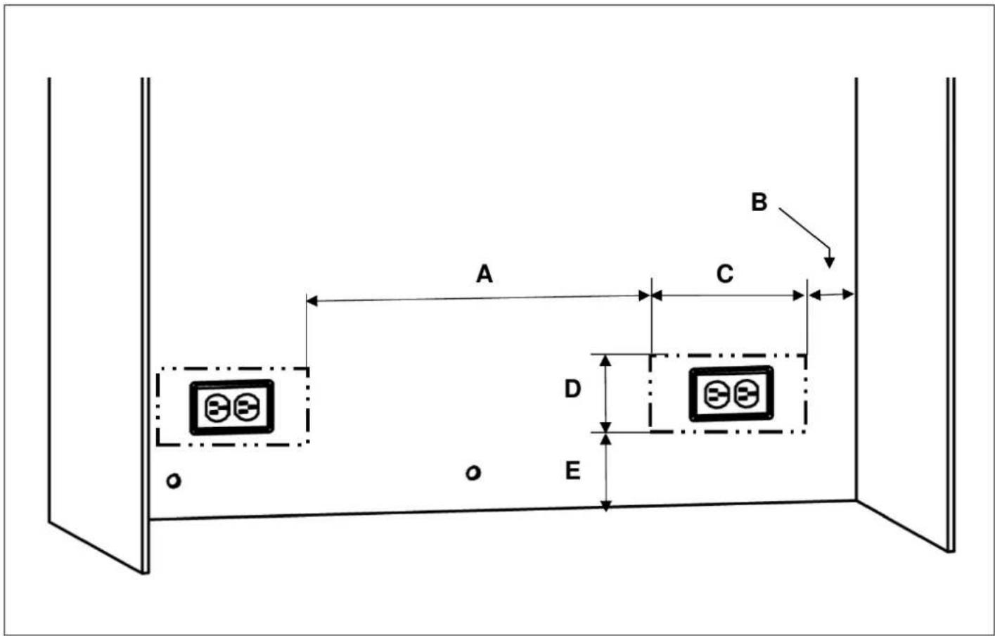
Fig. 92
| CONFIGURATION A B C D | E | ||||
| 45+60 cm (18"+24") | 330 mm (13") | 50.8 mm (2") | 280 mm (11") | 127 mm (5") | 102 mm (4") |
| 45+75 cm (18"+30") | 482 mm (19") | 50.8 mm (2") | 280 mm (11") | 127 mm (5") | 102 mm (4") |
| 60+60 cm (24"+24") | 330 mm (13") | 50.8 mm (2") | 280 mm (11") | 127 mm (5") | 102 mm (4") |
| 60+75 cm (24"+30") | 482 mm (19") | 50.8 mm (2") | 280 mm (11") | 127 mm (5") | 102 mm (4") |
| 75+75 cm (30"+30") | 482 mm (19") | 50.8 mm (2") | 280 mm (11") | 127 mm (5") | 102 mm (4") |
LOCATION OF THE WATER SYSTEM
Location of the water system should be as in the image below.
For technical aspects, refer to the PLUMBING REQUIREMENTS chapter.
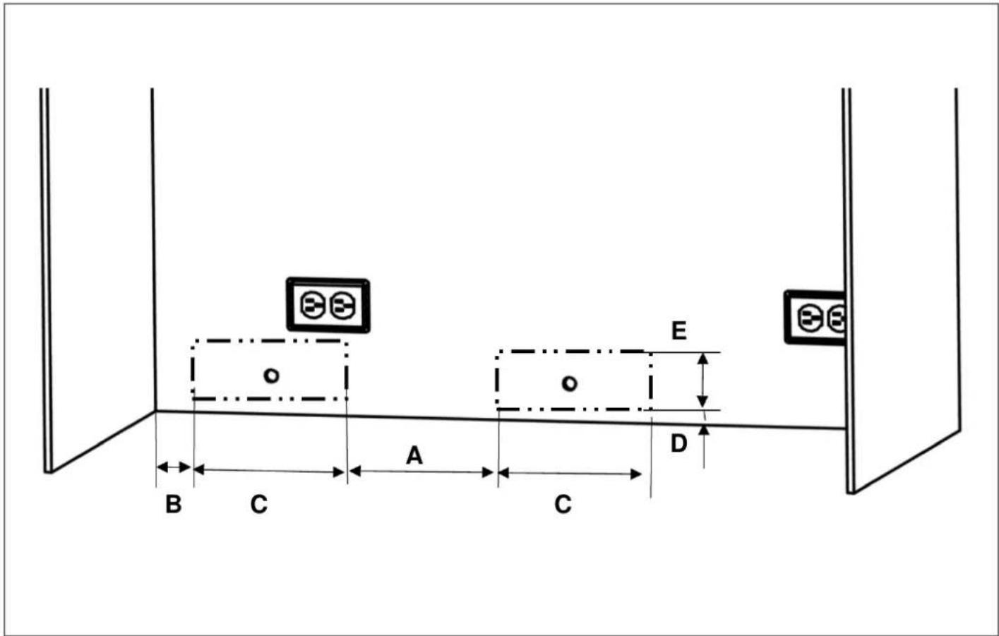
Fig. 93
| CONFIGURATION A B C D E | |||||
| 45+60 cm (18"+24") | 203 mm (8") | 50.8 mm (2") | 254 mm (10") | 21 mm (7/8") | 102 mm (4") |
| 45+75 cm (18"+30") | 203 mm (8") | 50.8 mm (2") | 254 mm (10") | 21 mm (7/8") | 102 mm (4") |
| 60+60 cm (24"+24") | 356 mm (14") | 50.8 mm (2") | 254 mm (10") | 21 mm (7/8") | 102 mm (4") |
| 60+75 cm (24"+30") | 356 mm (14") | 50.8 mm (2") | 254 mm (10") | 21 mm (7/8") | 102 mm (4") |
| 75+75 cm (30"+30") | 508 mm (20") | 50.8 mm (2") | 254 mm (10") | 21 mm (7/8") | 102 mm (4") |
flowchart
graph TD
    1 --> A["Shank"]
    2 --> B["Switch"]
    3 --> C["Pins"]
    4 --> D["Antenna"]
    5 --> E["Arrow"]
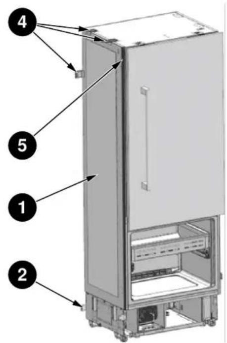
Fig. 94
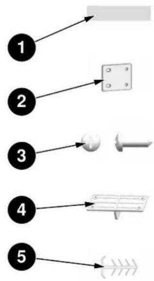
| NO PART NAME SPEC | Q'TY | ||
| 1 | Insulating Foam | Sponge, gray,T3.0*400*1750 | 1 |
| 2 Lower Bracket | T2.0, Cr+zn-coating | 1 | |
| 3 Screws M4*12 16 | |||
| 4 | Upper Brackets | POM | 3 |
| 5 | Central Trim PVC extrusion L=1876 | 1 | |
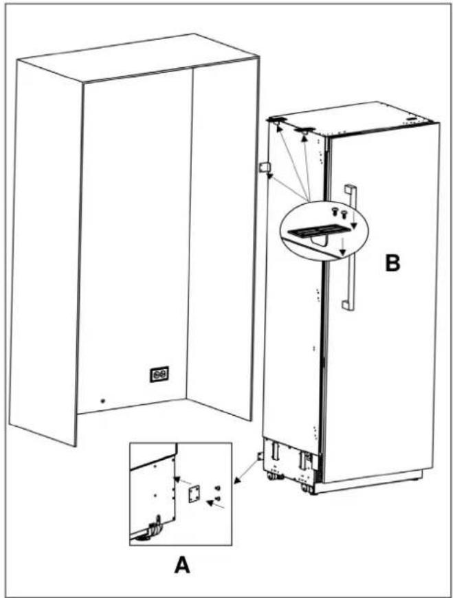
INSTALLING THE UPPER AND LOWER BRACKETS
• Install the Upper and Lower Brackets, as per the pictures below:
natural_image
Technical line drawing of a refrigerator with labeled components and an inset view showing internal wiring (no text or symbols present)Fig. 95
A Lower bracket
B Upper brackets
Attach the Insulating Foam centered to the side of one of the refrigerator units, as per the picture below:
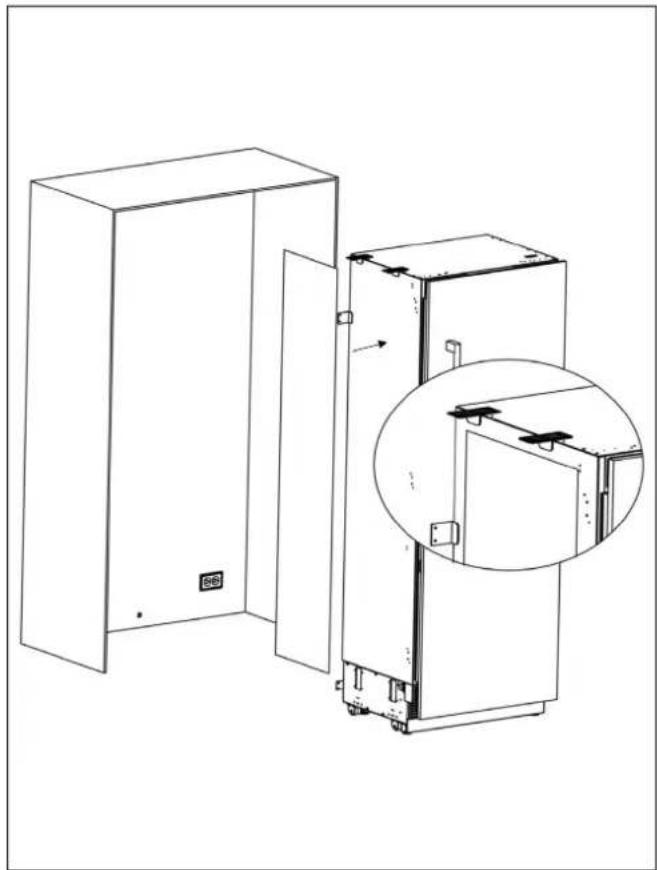
natural_image
Technical line drawing of a cabinet with an inset close-up showing internal components (no text or symbols)Fig. 96
Position the two refrigerators side-by-side, ensuring they are properly aligned.

WARNING
The insulating foam must be attached to the side of the unit that will be placed next to the other appliance, fitting it securely between the two units. Failure to do so may lead to condensation buildup.
- Once aligned, use screws to attach the Upper Brackets to both refrigerators. Refer to the pictures below for guidance:
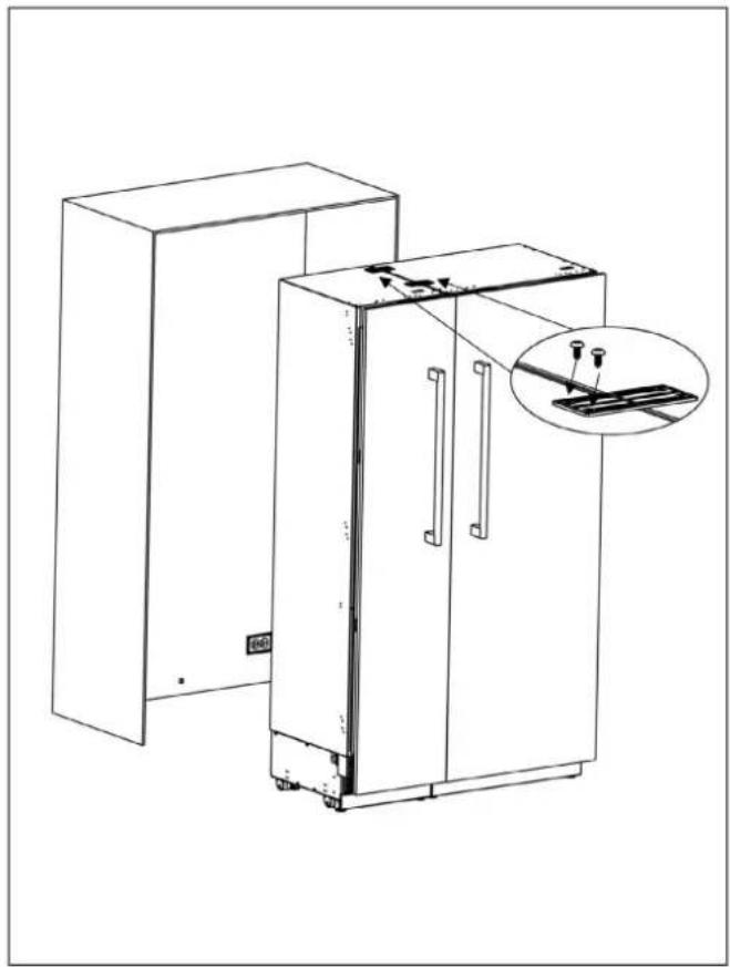
natural_image
Line drawing of a two-tier refrigerator with an inset showing the internal components (no text or symbols)Fig. 97
Once the refrigerators are properly aligned, secure the connecting brackets at the back and the front, joining the two refrigerators together.
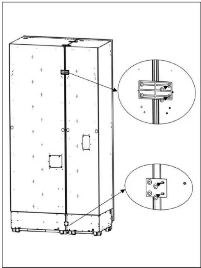
natural_image
Technical line drawing of a cabinet or enclosure with mounting holes and internal components, showing two views of the assembly (no text or symbols present)Fig. 98
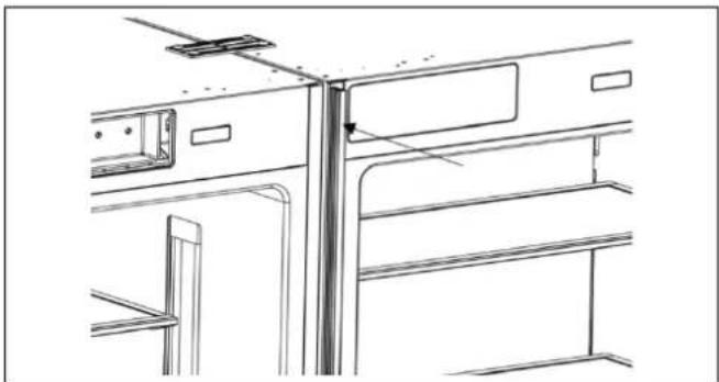
natural_image
Technical line drawing of a cabinet or enclosure with structural components (no text or symbols)Connect the power supply to the refrigerators.
- Install the water connections for the refrigerators, following the manufacturer's instructions.
• Gently push the refrigerators into their final position, making sure they are level and stable.
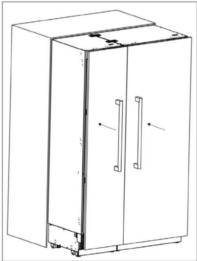
natural_image
Line drawing of a two-door refrigerator with handlebars and ventilation slots (no text or symbols)Fig. 99
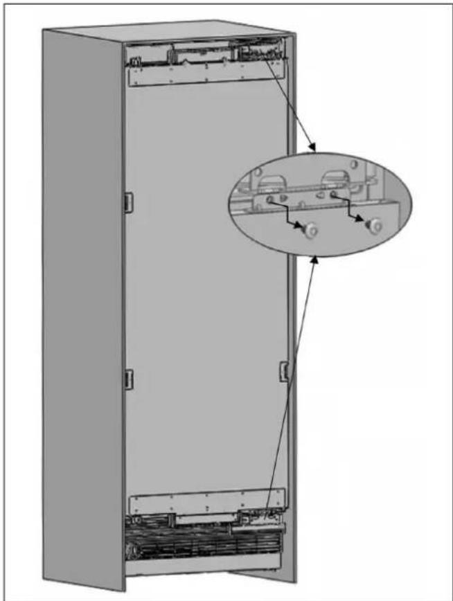
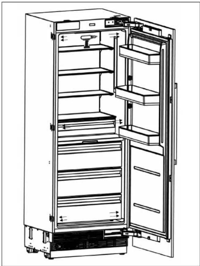
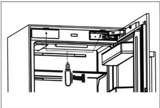
- Using a drill and the bit shown below, engage each of the refrigerator's adjuster shafts in turn and level the refrigerator.
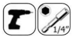
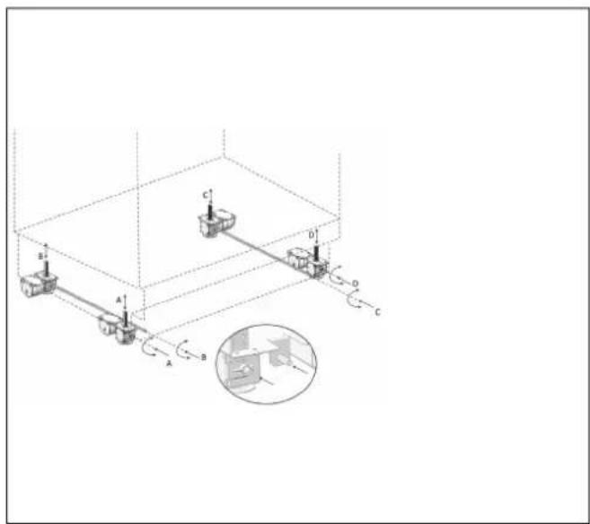
Fig. 100
Raise the front feet to reduce any risk of the cabinet falling frontward.
A/D – Rotate the shaft clockwise to raise the front feet
B/C – Rotate the shaft clockwise to raise the rear feet.
INSTALLING THE CONNECTION BRACKETS ON THE REFRIGERATOR'S SIDE WALLS
- Install the connection brackets to the refrigerator using 12 screws.
natural_image
Line drawing of an open refrigerator with doors open and shelves closed, showing internal compartments and ventilation slots (no text or labels)Fig. 101
INSTALLING THE CONNECTION BRACKETS ON THE REFRIGERATOR'S TOP WALL
- Attach the connection brackets to the refrigerator using 4 screws.
natural_image
Technical line drawing of an open refrigerator with internal compartments and a hanging tool (no text or symbols)Fig. 102
INSTALLING THE LATERAL AND UPPER TRIMS
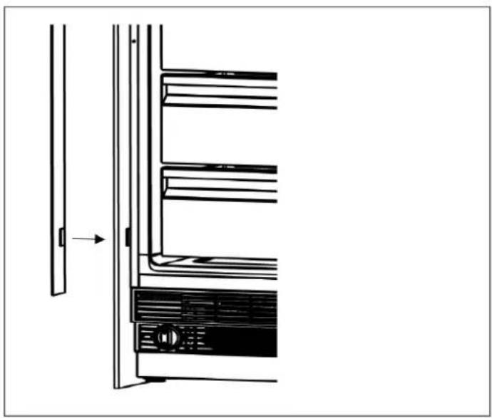
- Install the lateral trims onto the right and left connection brackets.
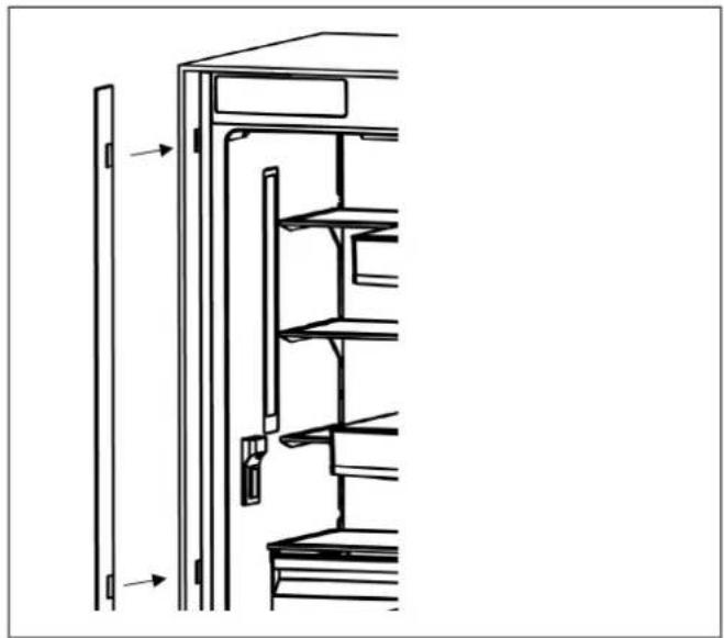
natural_image
Technical line drawing of a refrigerator interior with shelves and doors, showing structural components (no text or symbols)Fig. 103
natural_image
Diagram of a refrigerator interior showing front and side views with no text or symbolsFig. 104
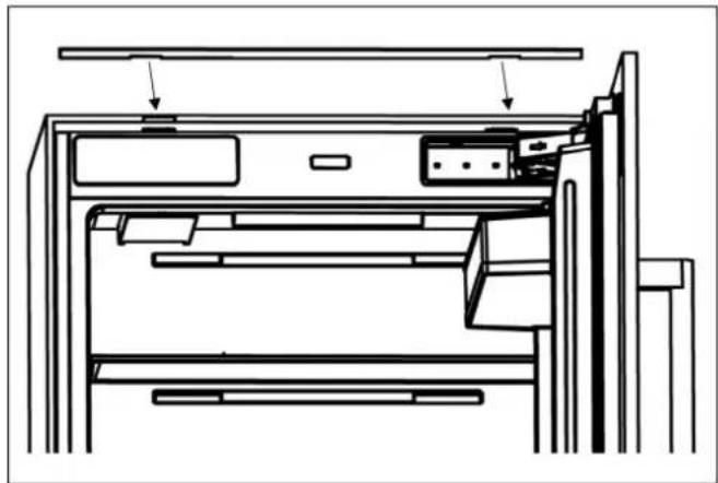
• Install the upper trim onto the upper connection brackets.
natural_image
Technical line drawing of a refrigerator interior showing front and rear compartments with no text or symbolsFig. 105
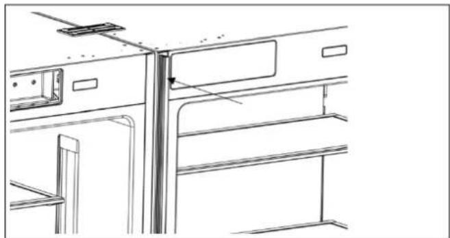
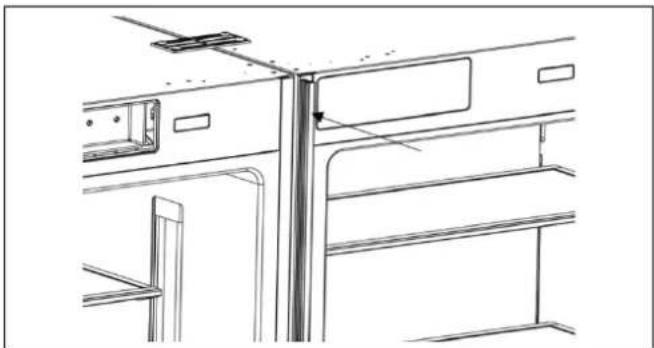
Ensure that the refrigerators are properly aligned before inserting the Center Trim (part #5).
Gently push the Center Trim between the refrigerators to securely fit it in place.
natural_image
Technical line drawing of a cabinet or enclosure with structural components (no text or symbols)Fig. 106

natural_image
Line drawing of a two-decker cabinet with two doors and handle bars (no text or symbols)Fig. 107
DALLA SCRIVANIA DEL PRESIDENTE
Gentile Cliente,
natural_image
Technical diagram of a mechanical assembly with dimension lines (no text or symbols)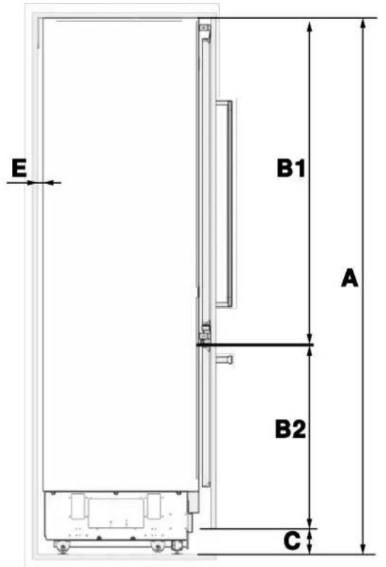
Fig. 4
| A B C D E F G H | ||||||
| 2134 mm(84") | 2030 mm(79 15/16") | 101 mm (4") 3 mm (1/8") | Remainingspace afterinstallation:19 mm (3/4") | 2 mm (1/16") | 574 mm(22 5/8") | 42 mm(1 5/8") |
POSIZIONE DELLE STAFFE ANTIRIBALTAMENTO
| IJK | |
| 2134 mm (84") 4 mm (5/32") | 2130 mm (83 7/8") |
REGOLAZIONE MINIMA DELL'ALTEZZA PER IL LIVELLAMENTO
| L | |
| Fronte | 8 mm (5/16") |
| Retro | 7 mm (1/4") |
CAPACITÀ DI CARICO DELLE VASCHETTE SU PORTA (ALIMENTI)
natural_image
Two views of an open refrigerator with doors open, showing internal shelves and doorways (no text or symbols)Fig. 5
CATEGORIA
RFZ45S5FPRS / RFZ45S5FPLS
RFZ60S5FPNS RLD60S5FPNS RLD75S5FPNS
Carico max.
10 kg (22 lb) 15 kg (33 lb) 15 kg (33 lb) 15 kg (33 lb)
PANNELLO PORTA PERSONALIZZATO (PER I MODELLI PREDISPOSTI PER IL PANNELLO)
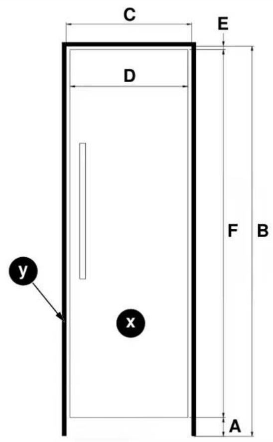
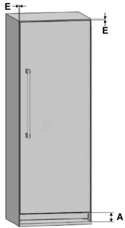
Fig. 6
• x: PANNELLO PORTA IN LEGNO
y: CABINET IN LEGNO
natural_image
3D line drawing of a cabinet with open door and internal compartments (no text or symbols)Fig. 9

AVVERTENZA
Fig. 10
Fig. 11
DISIMBALLAGGIO

AVVERTENZA
natural_image
3D architectural rendering of a rectangular building with vertical supports and horizontal beams (no text or symbols)Fig. 12
natural_image
Exploded view diagram of a refrigerator internal structure (no text or labels)Fig. 13

ATTENZIONE
natural_image
Technical diagram of a mechanical device with internal components and directional arrows indicating flow or movement (no text or symbols present)Fig. 16
MONTAGGIO DELLE STAFFE ANTIRIBALTAMENTO

AVVERTENZA
natural_image
Three black-and-white icons: a hammer, a rifle, and a glove, arranged in rounded squares (no text or symbols)
natural_image
Pure diagram of a mechanical or electrical component with no text, numbers, or symbolsFig. 19
natural_image
Technical diagram of a mechanical assembly with circular component and mounting base (no visible text or symbols)Fig. 24
natural_image
Diagram showing a mechanical device with a bracket and a vertical panel, no text or symbols presentFig. 25

NOTA
natural_image
Technical illustration of a server rack with zoomed-in views showing internal components (no text or symbols)Fig. 26

NOTA
Fig. 29
natural_image
Interior view of a server rack unit with open panel and internal components (no visible text or labels)Fig. 30
natural_image
Technical line drawing of a cabinet with an inset showing a cross-sectional view of the door frame (no text or symbols present)Fig. 31
natural_image
Technical line drawing of a refrigerator internal structure with an inset showing a close-up of the door panel (no text or symbols present)Fig. 34

NOTA
natural_image
Interior view of a refrigerator showing open doors, shelves, and internal compartments (no text or labels visible)Fig. 35
FISSAGGIO DELLA STAFFA SUPERIORE
• Fissare la staffa superiore al mobile con 4 viti (#13).

NOTA
natural_image
Line drawing of a cabinet interior showing front and rear panels with internal compartments (no text or symbols)Fig. 36
natural_image
Technical diagram of an industrial machine with labeled component A, showing internal components and wiring (no readable text or symbols)Fig. 37
natural_image
Technical line drawing of an industrial machine or machinery component with visible internal components and mounting brackets (no text or symbols)Fig. 38
natural_image
Technical diagram of a mechanical device with internal components and directional arrows indicating flow or movement (no text or symbols present)Fig. 39
FISSAGGIO DEI PROFILI DECORATIVI
natural_image
Technical line drawing of a door frame and refrigerator interior (no text or symbols)Fig. 40

NOTA
natural_image
Line drawing of a front view of a computer monitor with an open lid and drive bays (no text or symbols)Fig. 41
natural_image
3D mechanical assembly diagram showing a bracket with mounting holes and a small pin (no text or symbols)Fig. 43
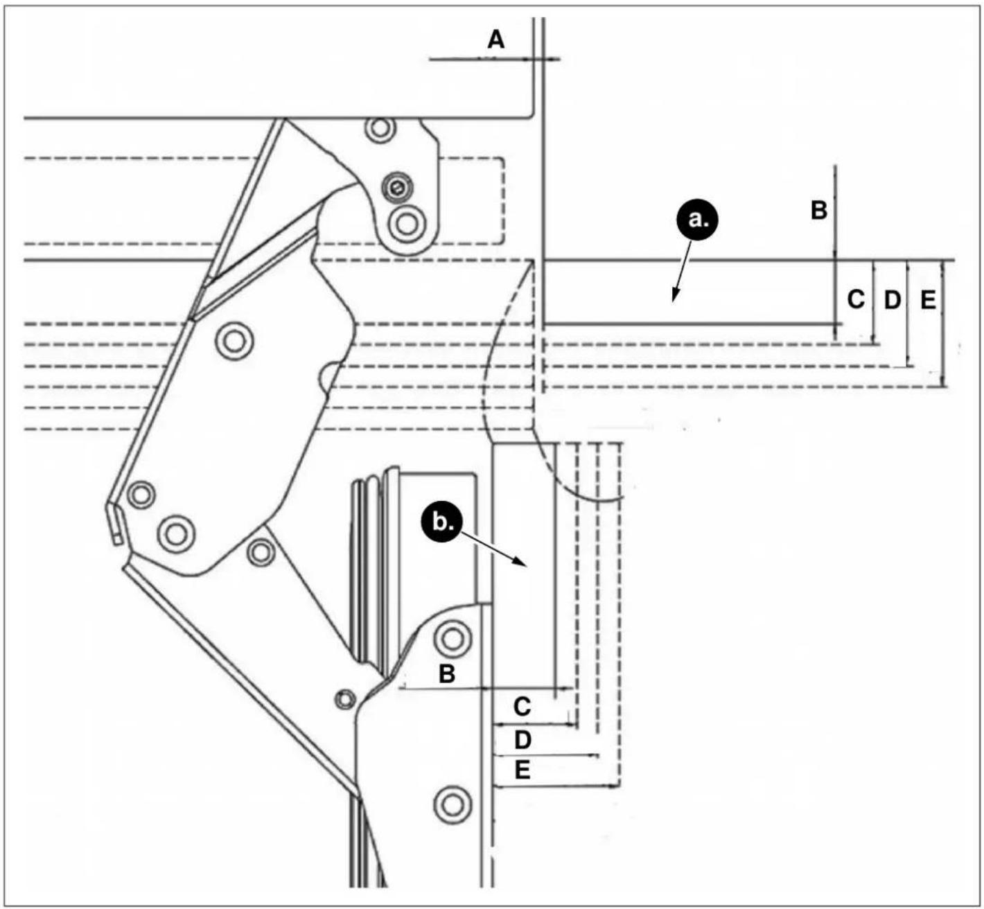
Fig. 44
a. Parte anteriore del mobiletto
b. Pannello frontale
A. 3 mm (1/8")
B. 19 mm (3/4")
C. 24 mm (15/16")
D. 32 mm (1 1/4")
E. 38 mm (1 1/2")
RIMOZIONE DELLE COPERTURE DEI MECCANISMI DEL PANNELLO DI RIVESTIMENTO
natural_image
Technical diagram of a door frame assembly with mounting bracket and control panel (no text or symbols)Fig. 45 RFZ45S5FPRS / RFZ45S5FPLS RFZ60S5FPNS RLD60S5FPNS
natural_image
Diagram of a refrigerator interior showing front panel, door, and side panel with directional arrows indicating movement (no text or symbols)Fig. 46 RLD75S5FPNS

AVVERTENZA
natural_image
Technical diagram showing a mechanical assembly with mounting brackets and a bracket, no text or symbols presentFig. 47
RIMOZIONE DELLE STAFFE DEL PANNELLO
natural_image
Technical illustration of an open refrigerator with visible door, shelves, and cooling unit (no text or labels)Fig. 48 RFZ45S5FPRS / RFZ45S5FPLS
natural_image
Technical illustration of an open refrigerator with visible door, shelves, and cooling unit (no text or labels)Fig. 49 RFZ60S5FPNS RLD60S5FPNS RLD75S5FPNS
natural_image
Diagram showing a rotating mechanical component with two plates and directional arrows indicating rotation (no text or symbols)Fig. 50
natural_image
Diagram showing a mechanical or structural assembly with downward arrows indicating motion, no text or symbols present.Fig. 51
natural_image
Diagram showing two rectangular panels with different shades of gray, one above a dark panel and the other below (no text or symbols)Fig. 52

AVVERTENZA
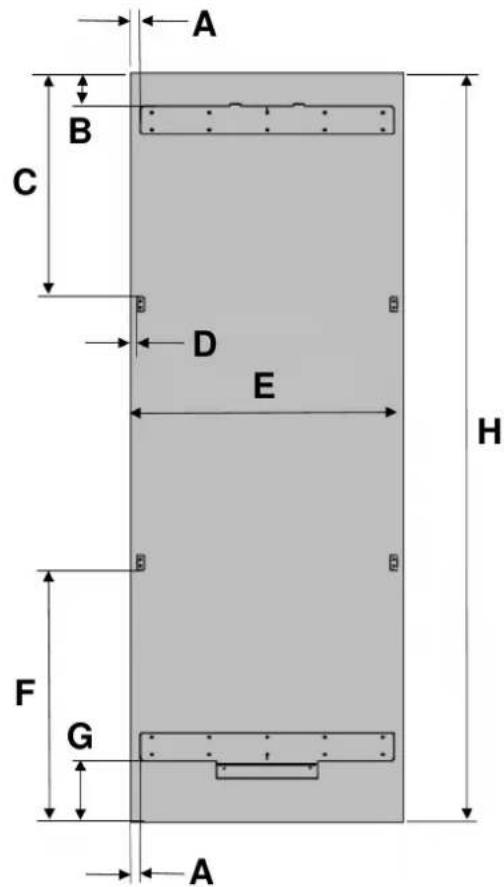
Fig. 53 RFZ45S5FPRS / RFZ45S5FPLS Fig. 54 RFZ60S5FPNS RLD60S5FPNS RLD75S5FPNS
| CATEGORIA | RFZ45S5FPRS / RFZ45S5FPLS | RFZ60S5FPNS RLD60S5FPNS RLD75S5FPNS |
| A | 10 mm (3/8") 10 mm (3/8") 10 mm (3/8") 10 mm (3/8") | |
| B | 85 mm (3 3/8") | |
| C | 595,5 mm (23 7/16") | |
| D | 18,2 mm (7/10") | |
| E | 451 mm (17 3/4") 603 mm (23 3/4") 603 mm (23 3/4") 756 mm (29 3/4") | |
| F | 693,5 mm (27 5/16") | |
| G | 175 mm (6 7/8") | |
| H | 2030 mm (79 15/16") | |

AVVERTENZA
natural_image
Simple line drawing of a mechanical setup with a piston and lever, no text or symbols presentFig. 57 RFZ45S5FPRS / RFZ45S5FPLS

AVVERTENZA
natural_image
Pure mechanical diagram showing a vertical frame with a curved arrow indicating motion or force (no text or symbols)Fig. 58
Fig. 59 RFZ60S5FPNS RLD60S5FPNS RLD75S5FPNS
natural_image
Technical line drawing of a door frame with two horizontal bars and two circular annotations indicating measurement points (no text or symbols present)Fig. 60
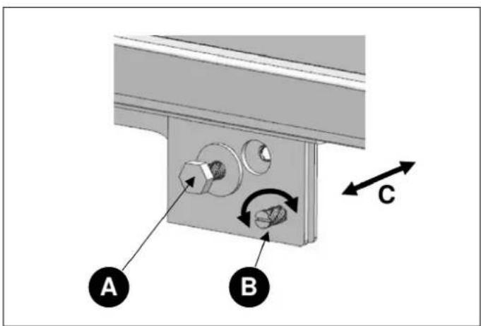
Fig. 61
natural_image
Three tool icons: a pencil, a wrench, and a hammer, displayed in separate rounded squares (no text or symbols)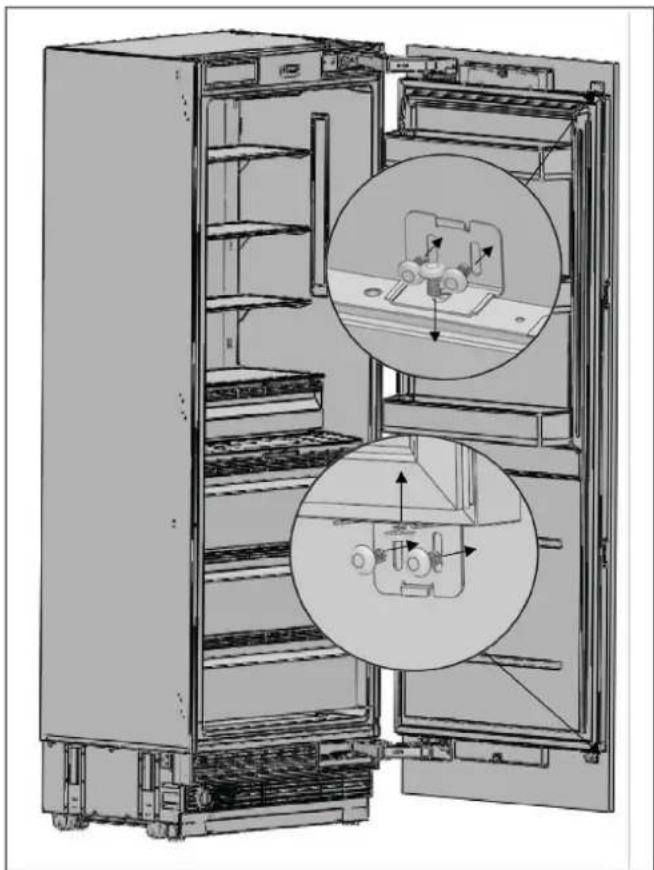
natural_image
Interior view of a refrigerator showing open doors and internal compartments with mechanical components (no text or symbols visible)Fig. 62 RFZ60S5FPNS RLD60S5FPNS RLD75S5FPNS
natural_image
Interior view of a refrigerator showing open doors, shelves, and a close-up of the door (no text or symbols visible)Fig. 63 RFZ60S5FPNS RLD60S5FPNS
RLD75S5FPNS
natural_image
Exploded view diagram of a refrigerator showing internal compartments and doorways (no text or labels)Fig. 64 RFZ45S5FPRS / RFZ45S5FPLS
natural_image
3D diagram of a refrigerator interior showing internal compartments and doorways (no text or labels)Fig. 65 RFZ60S5FPNS RLD60S5FPNS
natural_image
3D rendering of an open refrigerator with visible door, shelves, and cooling unit (no text or symbols)Fig. 66 RLD75S5FPNS

AVVERTENZA
natural_image
Technical diagram of a multi-panel refrigerator with an inset showing a close-up view of the front panel (no text or symbols present)Fig. 67
natural_image
Technical diagram showing a mechanical component with a labeled section A, no text or symbols presentFig. 68
A Nastro doppio
natural_image
Technical line drawing of a multi-tiered refrigerator with two vertical supports and an arrow indicating direction (no text or symbols)Fig. 69
natural_image
Technical line drawing of an open refrigerator with a circular inset showing internal components (no text or symbols)Fig. 70

AVVERTENZA
natural_image
Technical line drawing of an open refrigerator with internal compartments and a circular inset showing a device (no text or symbols present)Fig. 71

ATTENZIONE
natural_image
Technical diagram of a door frame with two vertical supports and horizontal slots, no text or symbols presentFig. 72
natural_image
Diagram of a refrigerator interior with an upward arrow indicating motion (no text or symbols)Fig. 73 RFZ45S5FPRS / RFZ45S5FPLS
natural_image
3D technical diagram of a mechanical assembly with an upward arrow indicating force or direction (no text or symbols present)Fig. 74 RFZ60S5FPNS RLD60S5FPNS
natural_image
Diagram of a door with two arrows indicating upward motion, showing internal components and structure (no text or symbols)Fig. 75 RLD75S5FPNS
natural_image
Diagram showing a monitor mounted on a wall with a separate panel and a downward arrow indicating motion (no text or symbols)Fig. 76 RFZ45S5FPRS / RFZ45S5FPLS
natural_image
Diagram of a monitor with a cable attachment and two arrows indicating downward motion (no text or symbols)Fig. 78 RLD75S5FPNS
natural_image
Diagram showing a device with a lock and a separate component, no text or symbols presentFig. 77 RFZ60S5FPNS RLD60S5FPNS
natural_image
Interior view of a refrigerator with open doors and shelves (no text or symbols visible)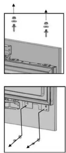
natural_image
Technical diagram showing two views of a mechanical assembly with arrows indicating direction (no text or symbols present)Fig. 79 RFZ45S5FPRS / RFZ45S5FPLS
natural_image
Interior view of a refrigerator showing open doors, shelves, and storage compartments (no text or labels visible)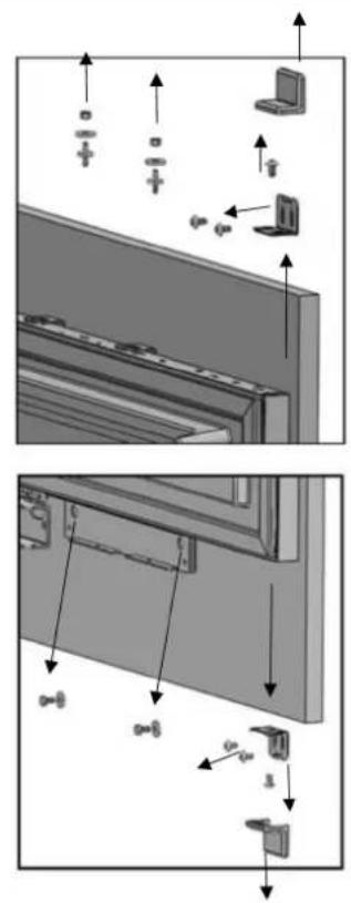
Fig. 80 RFZ60S5FPNS RLD60S5FPNS RLD75S5FPNS
natural_image
Technical diagram of an open electrical cabinet with internal components and a magnified inset showing internal wiring (no text or labels)Fig. 81
natural_image
Technical line drawing of a vertical panel or enclosure with horizontal and diagonal lines indicating internal structure (no text or symbols)Fig. 82
SOSTITUZIONE DELLA SCHEDA MADRE
natural_image
Diagram of a tall refrigerator with an open door and internal compartments, showing no text or symbols.Fig. 83
natural_image
Technical line drawing of a multi-tier refrigerator cabinet (no text or labels)Fig. 84
natural_image
Technical illustration of a mechanical device showing front and side views with no visible text or symbolsFig. 85
Fig. 87
natural_image
Technical line drawing of a multi-tiered refrigerator cabinet (no text or labels)Fig. 88
natural_image
Interior view of a tall refrigerator with an open door and internal shelves, showing no text or symbols.Fig. 89
RIMONTAGGIO DELLE PORTE.
natural_image
Diagram of a cabinet interior showing internal components and a magnified view of the door (no text or symbols present)Fig. 90
Fig. 92
| CONFIGURAZIONE A B C D E | |||||
| 45+60 cm (18"+24") | 330 mm (13") | 50,8 mm (2") | 280 mm (11") | 127 mm (5") | 102 mm (4") |
| 45+75 cm (18"+30") | 482 mm (19") | 50,8 mm (2") | 280 mm (11") | 127 mm (5") | 102 mm (4") |
| 60+60 cm (24"+24") | 330 mm (13") | 50,8 mm (2") | 280 mm (11") | 127 mm (5") | 102 mm (4") |
| 60+75 cm (24"+30") | 482 mm (19") | 50,8 mm (2") | 280 mm (11") | 127 mm (5") | 102 mm (4") |
| 75+75 cm (30"+30") | 482 mm (19") | 50,8 mm (2") | 280 mm (11") | 127 mm (5") | 102 mm (4") |
Fig. 94
| ICE MAKER NOME SPEC. | Q.TÀ | |
| 1 Schiuma isolante | Schiuma, grigio,T3.0*400*1750 | 1 |
| 2 Staffa inferiore | T2.0, Rivestimento in Cr+Zn | 1 |
| 3 Viti M4*12 16 | ||
| 4 | Staffa superiore POM 3 | |
| 5 Finitura centrale | PVC estruso, L = 1876 | 1 |
INSTALLAZIONE DELLE STAFFE SUPERIORI E INFERIORI
natural_image
Technical line drawing of a refrigerator with labeled components and an inset view showing internal components (no text or symbols present)Fig. 95
A Staffe superiori
• B Staffe inferiori
natural_image
Technical line drawing of a refrigerator with an inset close-up showing internal components (no text or symbols)Fig. 96
natural_image
Line drawing of a two-tier refrigerator with an inset showing a close-up of the front panel (no text or symbols present)Fig. 97
natural_image
Technical line drawing of a cabinet or enclosure with mounting holes and internal components, showing two views of the cabinet (no text or symbols present)Fig. 98
natural_image
Technical line drawing of a cabinet or enclosure with structural components (no text or symbols)natural_image
Line drawing of a two-door refrigerator with handlebars and side-mounted doors, showing internal structure and mounting points (no text or symbols)Fig. 99
Fig. 100
natural_image
Line drawing of an open refrigerator with doors open and shelves closed, showing internal compartments and ventilation slots (no text or labels)Fig. 101
INSTALLAZIONE DELLE STAFFE DI COLLEGAMENTO SULLA PARETE SUPERIORE DEL FRIGORIFERO
natural_image
Technical line drawing of an open refrigerator with internal compartments and a hanging tool (no text or symbols)Fig. 102
INSTALLAZIONE DELLE FINITURE LATERALI E SUPERIORI
natural_image
Technical line drawing of a refrigerator interior with shelves and doors, showing structural components (no text or symbols)Fig. 103
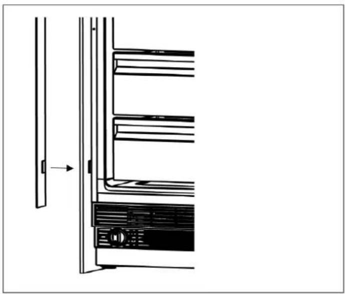
natural_image
Diagram of a refrigerator interior showing front and side views with no text or symbolsFig. 104
natural_image
Technical line drawing of a mechanical device interior showing internal components and mounting brackets (no text or symbols)Fig. 105
natural_image
Technical line drawing of a cabinet or rack structure with mounting brackets and structural supports (no text or symbols)Fig. 106
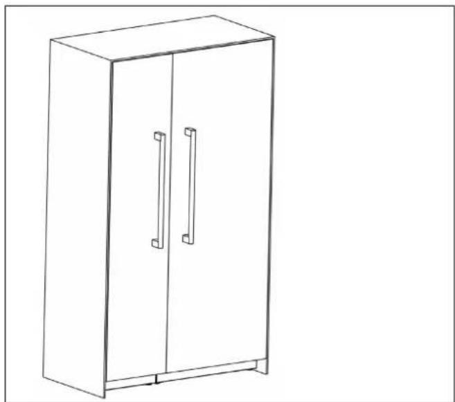
natural_image
Line drawing of a two-decker cabinet with two doors and two handles (no text or symbols)Fig. 107
DU BUREAU DE NOTRE PRÉSIDENT
DIMENSIONS DU PRODUIT 140
EMPLACEMENT DE LA BRIDE ANTIBASCULEMENT 142
RÉGLAGE MINIMUM DE LA HAUTEUR POUR LA MISE À NIVEAU 142
CAPACITÉ DE CHARGEMENT DES BALCONNETS DE PORTE DU RÉFRIGÉRATEUR 142
PANNEAU DE PORTE PERSONNALISÉ (POUR LES MODÈLES AVEC PANNEAU PERSONNALISÉ) 143
EXIGENCES ÉLECTRIQUES 144
EXIGENCES EN MATIÈRE DE PLOMBERIE 146
INSTALLATION 148
LISTE DES OUTILS 149
ALTERNATIVES POUR L'INSTALLATION 149
DÉBALLAGE 150
RETRAIT DES CONNECTEURS SUR LA PAROI LATÉRALE DE L'UNITÉ 151
RETRAIT DU MATÉRIEL D'INSTALLATION 152
RETRAIT DE L'ENSEMBLE ÉVENTS D'AÉRATION 153
INSTRUCTIONS D'INSTALLATION 154
MONTAGE DES SUPPORTS ANTI-BASCULEMENT 154
PRÉPARATION DU TUYAU D'EAU ET DU RACCORDEMENT ÉLECTRIQUE 158
INSTALLATION DANS L'ARMOIRE 159
VISSAGE DES SUPPORTS LATÉRAUX 164
SÉCURISATION DU SUPPORT SUPÉRIEUR 165
INSTALLATION DE L'ARMOIRE INFÉRIEURE 166
FIXATION DE LA GRILLE D'AÉRATION 167
FIXATION DES REVÊTEMENTS DE GARNITURE 167
INSTALLATION ET PRÉPARATION DES PANNEAUX DE RECOUVREMENT 168
RÉGLAGE DE LA CHARNIÈRE ET INVERSION DU SENS D'OUVERTURE DE LA PORTE 180
INSTALLATION DE LA CONFIGURATION CÔTE À CÔTE 189
DIMENSIONS DE DÉCOUPE DE L'ARMOIRE 189
EMPLACEMENT DU CÂBLAGE ÉLECTRIQUE 190
EMPLACEMENT DU SYSTÈME D'ALIMENTATION EN EAU 191
INSTALLATION DES ATTACHES SUPÉRIEURES ET INFÉRIEURES 193
Fig. 2 Fig. 3
α 90°
β 115°
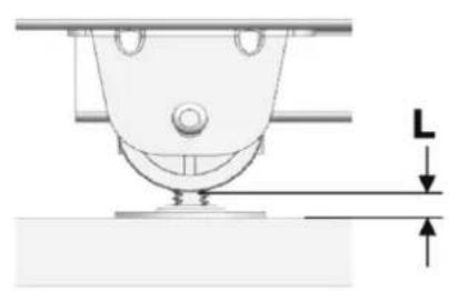
natural_image
Technical diagram of a mechanical assembly with dimension lines (no text or symbols)Fig. 4
A B C D E F G H
| 2134 mm(84") | 2030 mm(79 15/16") | 101 mm (4") 1/8" (3 mm) | Espace résiduel après installation :19 mm (3/4") | 2 mm (1/16") | 574 mm(22 5/8") | 42 mm(1 5/8") |
EMPLACEMENT DE LA BRIDE ANTIBASCULEMENT
| IJK | |
| 2134 mm (84") 4 mm (5/32") | 2130 mm (83 7/8") |
RÉGLAGE MINIMUM DE LA HAUTEUR POUR LA MISE À NIVEAU
| L | |
| Avant | 8 mm (5/16") |
| Arrière | 7 mm (1/4") |
CAPACITÉ DE CHARGEMENT DES BALCONNETS DE PORTE DU RÉFRIGÉRATEUR
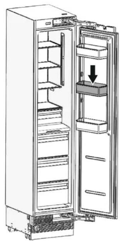
natural_image
Diagram of an open refrigerator with shelves and door, showing internal structure and a downward arrow indicating a drop (no text or symbols present)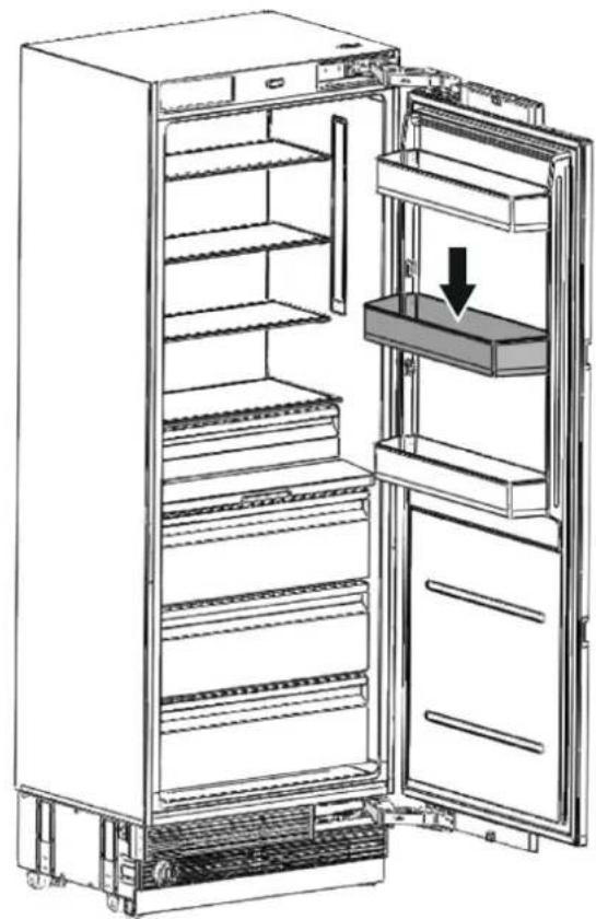
natural_image
Line drawing of an open refrigerator with a downward arrow indicating the interior portion (no text or symbols present)Fig. 5
| CATÉGORIE | RFZ45S5FPRS / RFZ45S5FPLS | RFZ60S5FPNS | RLD60S5FPNS | RLD75S5FPNS |
| Charge maximale | 22 lbs (10 kg) | 33 lbs (15 kg) | 33 lbs (15 kg) | 33 lbs (15 kg) |
PANNEAU DE PORTE PERSONNALISÉ (POUR LES MODÈLES AVEC PANNEAU PERSONNALISÉ)
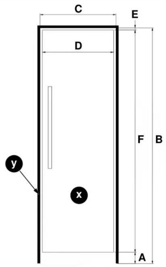
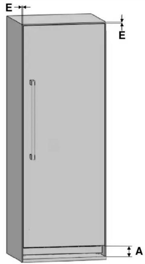
natural_image
3D line drawing of a cabinet with open door and internal compartments (no text or symbols)Fig. 9

MISE EN GARDE
Fig. 10
Fig. 11
DÉBALLAGE

MISE EN GARDE
natural_image
3D architectural rendering of a rectangular building facade with vertical supports and horizontal beams (no text or symbols)Fig. 12
natural_image
Exploded view diagram of a refrigerator internal structure (no text or labels)Fig. 13

ATTENTION!
natural_image
Technical diagram of an air conditioner unit with airflow arrows indicating airflow direction (no text or symbols present)Fig. 16
MONTAGE DES SUPPORTS ANTI- BASCULEMENT

MISE EN GARDE
natural_image
Pure diagram of a mechanical or electrical component with no text, numbers, or symbolsFig. 19
natural_image
Technical diagram of a mechanical assembly with circular component and mounting base (no visible text or symbols)Fig. 24
natural_image
Diagram showing a mechanical device with a bracket and a vertical panel, no text or symbols presentFig. 25

NOTE
natural_image
Technical diagram of a server rack with zoomed-in views showing internal components (no text or labels)Fig. 26

NOTE
Fig. 29
natural_image
Interior view of a server rack unit showing internal components and wiring (no text or symbols visible)Fig. 30
natural_image
Technical line drawing of a cabinet or enclosure with internal components and a magnified inset showing internal structure (no text or symbols)Fig. 31
natural_image
Technical line drawing of a refrigerator internal structure with an inset showing a close-up of the front panel (no text or symbols present)Fig. 34

NOTE
natural_image
Interior view of a refrigerator showing open doors, shelves, and internal compartments (no text or labels visible)Fig. 35
SÉCURISATION DU SUPPORT SUPÉRIEUR
natural_image
Line drawing of a refrigerator interior showing front and side views (no text or symbols)Fig. 36
INSTALLATION DE L'ARMOIRE INFÉRIEURE
natural_image
Technical diagram of an industrial machine with labeled component A, showing internal components and wiring (no readable text or symbols)Fig. 37
natural_image
Technical illustration of an industrial machine with visible internal components and mounting brackets (no text or symbols)Fig. 38
FIXATION DE LA GRILLE D'AÉRATION
natural_image
Technical diagram of a mechanical device showing internal components and airflow direction (no text or symbols)Fig. 39

NOTE
natural_image
Technical line drawing of a door panel and refrigerator interior (no text or symbols)Fig. 40
natural_image
Line drawing of a computer front panel with control buttons and a door (no text or symbols)Fig. 41
INSTALLATION ET PRÉPARATION DES PANNEAUX DE RECOUVREMENT
natural_image
3D mechanical assembly diagram showing a bracket with mounting holes and a small pin (no text or symbols)Fig. 43
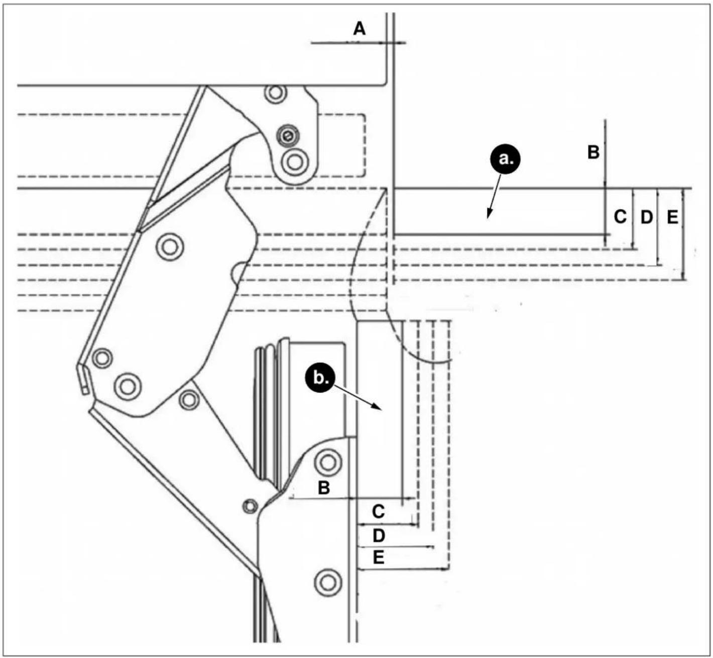
Fig. 44
a. Avant de l'armoire
b. Panneau avant
A. 3 mm (1/8")
B. 19 mm (3/4")
C. 24 mm (15/16")
D. 32 mm (1 1/4")
E. 38 mm (1 1/2")
RETRAIT DES COUVERCLES DU MÉCANISME DES PANNEAUX DE REVÊTEMENT
natural_image
Technical diagram of a door frame assembly with mounting bracket and control panel (no text or symbols)Fig. 45 RFZ45S5FPRS / RFZ45S5FPLS RFZ60S5FPNS RLD60S5FPNS
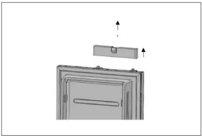
natural_image
Diagram of a refrigerator interior showing front and side views with arrows indicating movement (no text or symbols)Fig. 46 RLD75S5FPNS

MISE EN GARDE
natural_image
Technical diagram showing a mounted device with mounting brackets and a separate panel assembly (no text or symbols)Fig. 47
RETRAIT DES SUPPORTS DE PANNEAU
natural_image
Exploded view diagram of an open refrigerator showing internal compartments and doorways (no text or labels)Fig. 48 RFZ45S5FPRS / RFZ45S5FPLS
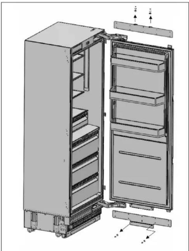
natural_image
Technical illustration of an open refrigerator with visible door, shelves, and cooling unit (no text or labels)Fig. 49 RFZ60S5FPNS RLD60S5FPNS RLD75S5FPNS
PRÉPARATION DES PANNEAUX DE REVÊTEMENT

NOTE
natural_image
Diagram showing a rotating mechanical component with two plates and directional arrows indicating rotation (no text or symbols)Fig. 50
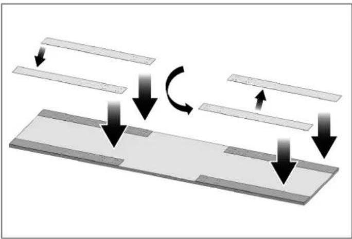
natural_image
Diagram showing a mechanical or structural assembly with downward arrows indicating motion, no text or symbols present.Fig. 51
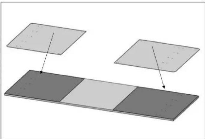
natural_image
Diagram showing two rectangular panels with different shades of gray, one above a dark segment and the other below, with no visible text or symbols.Fig. 52

MISE EN GARDE
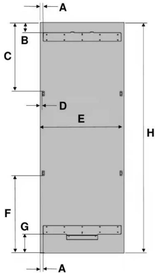
Fig. 53 RFZ45S5FPRS / RFZ45S5FPLS Fig. 54 RFZ60S5FPNS RLD60S5FPNS RLD75S5FPNS
| CATÉGORIE | RFZ45S5FPRS / RFZ45S5FPLS | RFZ60S5FPNS RLD60S5FPNS RLD75S5FPNS |
| A | 10 mm (3/8") 10 mm (3/8") 10 mm (3/8") 10 mm (3/8") | |
| B | 85 mm (3 3/8") | |
| C | 595,5 mm (23 7/16") | |
| D | 18,2 mm (7/10") | |
| E | 451 mm (17 3/4") 603 mm (23 3/4") 603 mm (23 3/4") 756 mm (29 3/4") | |
| F | 693,5 mm (27 5/16") | |
| G | 175 mm (6 7/8") | |
| H | 2030 mm (79 15/16") | |

MISE EN GARDE
Fig. 56 RFZ60S5FPNS RLD60S5FPNS RLD75S5FPNS
natural_image
Simple line drawing of a mechanical setup with a piston and lever, no text or symbols presentFig. 57 RFZ45S5FPRS / RFZ45S5FPLS

MISE EN GARDE
natural_image
Technical line drawing of a mechanical component with a curved arrow indicating rotation (no text or symbols)Fig. 58
ALIGNEMENT DE LA PARTIE SUPÉRIEURE DU PANNEAU DE PORTE PERSONNALISÉ À L'AIDE DE BOULONS
Fig. 59 RFZ60S5FPNS RLD60S5FPNS RLD75S5FPNS
natural_image
Technical line drawing of a door frame with two horizontal bars and two circular annotations indicating measurement points (no text or symbols present)Fig. 60
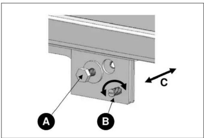
Fig. 61
natural_image
Interior view of a refrigerator showing open doors and internal compartments with mechanical components (no text or symbols visible)Fig. 62 RFZ60S5FPNS RLD60S5FPNS RLD75S5FPNS
natural_image
Interior view of a refrigerator showing open doors, shelves, and a close-up of the front panel (no text or symbols visible)Fig. 63 RFZ60S5FPNS RLD60S5FPNS
RLD75S5FPNS
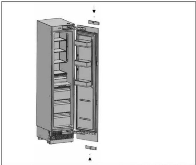
natural_image
Exploded view diagram of a refrigerator showing internal compartments and doorways (no text or labels)Fig. 64 RFZ45S5FPRS / RFZ45S5FPLS
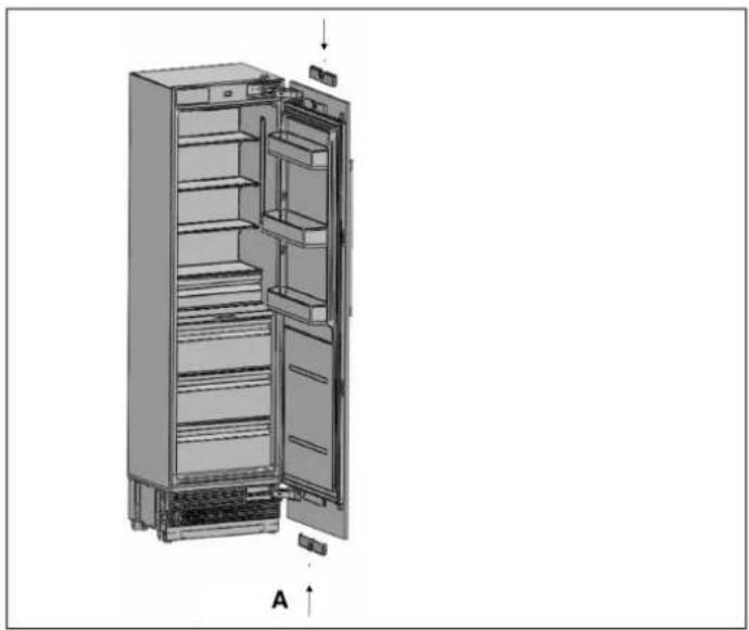
natural_image
3D diagram of a refrigerator interior showing internal compartments and doorways (no text or labels)Fig. 65 RFZ60S5FPNS RLD60S5FPNS
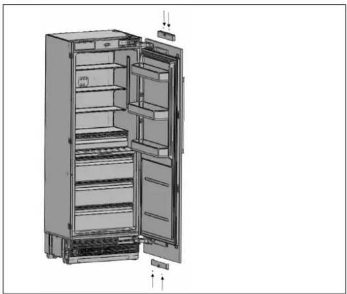
natural_image
3D rendering of an open refrigerator with visible door, shelves, and cooling unit (no text or symbols)Fig. 66 RLD75S5FPNS

MISE EN GARDE
natural_image
Technical diagram of a multi-panel refrigerator with an inset showing a close-up of the front panel (no text or symbols present)Fig. 67
natural_image
Technical line drawing of a mechanical component with labeled section A (no text or symbols beyond label)Fig. 68
natural_image
Technical line drawing of a multi-tiered refrigerator with vertical supports and horizontal shelves, shown with directional arrows (no text or symbols)Fig. 69
RÉGLAGE DE LA CHARNIÈRE ET INVERSION DU SENS D'OUVERTURE DE LA PORTE
RÉGLAGE DE LA TENSION DU RESSORT DES CHARNIÈRES
natural_image
Technical line drawing of an open refrigerator with a circular inset showing internal components (no text or symbols)Fig. 70

MISE EN GARDE
natural_image
Technical line drawing of an open refrigerator with a circular inset showing the interior portion (no text or symbols)Fig. 71

ATTENTION!
natural_image
Technical line drawing of a door frame with two vertical supports and horizontal bars, no text or symbols presentFig. 72
natural_image
Diagram of a door with an open lid and a handle, showing a mechanical assembly (no text or symbols)Fig. 73 RFZ45S5FPRS / RFZ45S5FPLS
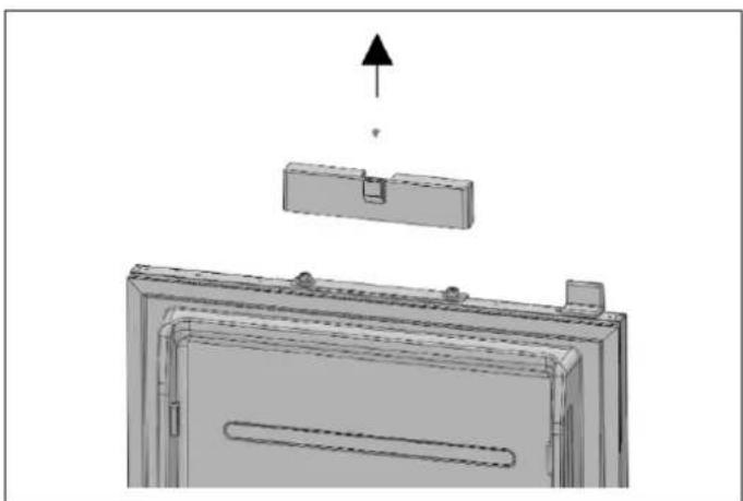
natural_image
3D technical diagram of a mechanical assembly with an upward arrow indicating force or direction (no text or symbols present)Fig. 74 RFZ60S5FPNS RLD60S5FPNS
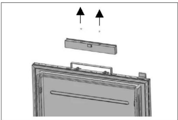
natural_image
Diagram of a door with two arrows indicating upward motion, showing internal components and structure (no text or symbols)Fig. 75 RLD75S5FPNS
natural_image
Diagram showing a monitor mounted on a wall with a separate panel and a downward arrow indicating motion (no text or symbols)Fig. 76 RFZ45S5FPRS / RFZ45S5FPLS
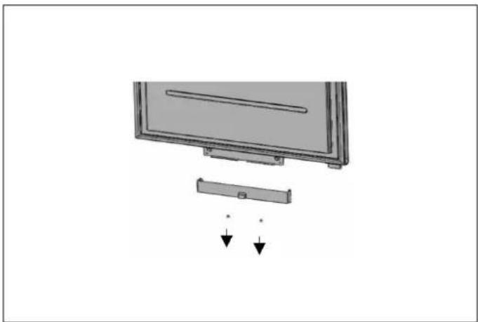
natural_image
Diagram of a monitor with an attached cable and two arrows indicating downward motion (no text or symbols)Fig. 78 RLD75S5FPNS
natural_image
Diagram showing a device with a lock and a connector, no text or symbols presentFig. 77 RFZ60S5FPNS RLD60S5FPNS
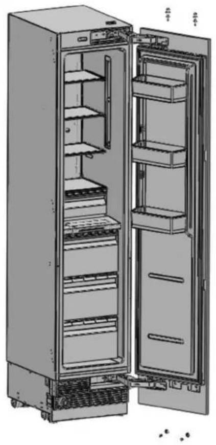
natural_image
Interior view of a refrigerator with open doors and shelves (no text or symbols visible)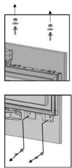
natural_image
Technical diagram showing two views of a mechanical assembly with arrows indicating direction (no text or symbols present)Fig. 79 RFZ45S5FPRS / RFZ45S5FPLS
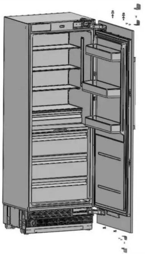
natural_image
Interior view of a refrigerator showing open doors, shelves, and storage compartments (no text or labels visible)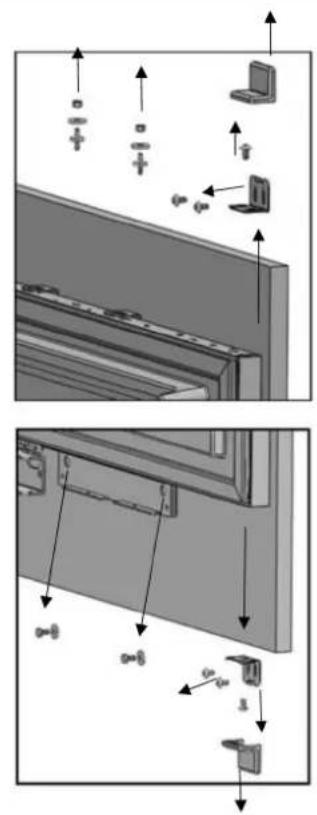
Fig. 80 RFZ60S5FPNS RLD60S5FPNS RLD75S5FPNS
natural_image
Technical diagram of an open electrical cabinet with internal components and a magnified inset showing internal wiring (no text or symbols present)Fig. 81
natural_image
Technical line drawing of a rectangular enclosure with horizontal and vertical lines, no text or symbols presentFig. 82
REEMPLACEMENT DES CHARNIÈRES
natural_image
Diagram of a refrigerator with an open door and internal compartments, showing no text or symbols.Fig. 83
natural_image
3D line drawing of a multi-tier refrigerator cabinet with open doors and internal shelves (no text or labels)Fig. 84
CHANGEMENT DE L'ORIENTATION DE LA PARTIE SUPÉRIEURE DE L'ÉVENT D'AÉRATION
natural_image
Technical illustration of a mechanical device showing front and side views of internal components (no text or symbols)Fig. 85
CHANGEMENT DE L'ORIENTATION DE LA PARTIE SUPÉRIEURE DE L'ÉVENT D'AÉRATION
Fig. 87
natural_image
3D line drawing of a multi-tiered refrigerator cabinet with visible shelves and doorways (no text or labels)Fig. 88
natural_image
Interior view of a refrigerator with open doors and shelves, showing internal compartments and a close-up of the door (no text or symbols visible)Fig. 89
RÉINSTALLATION DE LA PORTE
natural_image
Diagram of an open refrigerator with internal components and a magnified inset showing internal wiring (no text or symbols)Fig. 90
flowchart
graph TD
    1["1"] --> A["Square component"]
    2["2"] --> A
    3["3"] --> B["Head and nut"]
    4["4"] --> C["Grid-like structure"]
    5["5"] --> D["Arrow pointing left"]
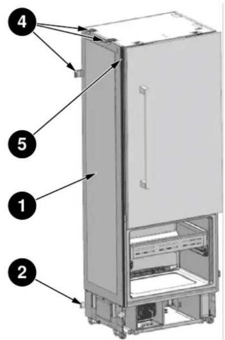
Fig. 94
| NON | NOM DE LA PIÈCE SPÉCIFICATIONS | QTÉ | |
| 1 Mousse isolante | Mousse, grise,T3.0*400*1750 | 1 | |
| 2 | Supports inférieurs | T2.0, revêtement Cr+zn | 1 |
| 3 Vis | M4*12 | 16 | |
| 4 | Attaches supérieures POM | 3 | |
| 5 | Garniture centrale Extrusion de PVC L=1876 1 | ||
INSTALLATION DES ATTACHES SUPÉRIEURES ET INFÉRIEURES
natural_image
Technical line drawing of a refrigerator with labeled components and an inset view showing internal components (no text or symbols present)Fig. 95
natural_image
Technical line drawing of a cabinet with an inset close-up showing internal components (no text or symbols)Fig. 96
natural_image
Line drawing of a cabinet with an inset showing a close-up of the front panel (no text or symbols present)Fig. 97
natural_image
Technical line drawing of a cabinet or enclosure with mounting holes and internal components, showing two views of the assembly (no text or symbols present)Fig. 98

natural_image
Technical line drawing of a cabinet or enclosure structure with mounting brackets and structural elements (no text or symbols)natural_image
Technical line drawing of a two-door refrigerator with handlebars and mounting feet (no text or symbols)Fig. 99
Fig. 100
natural_image
Line drawing of an open refrigerator with doors open and shelves closed, showing internal compartments and ventilation slots (no text or labels)
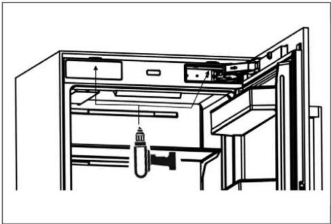
natural_image
Technical line drawing of an open refrigerator with internal compartments and a hanging tool (no text or symbols)Fig. 102
Fig. 101
INSTALLATION DES GARNITURES LATÉRALES ET SUPÉRIEURES
natural_image
Technical line drawing of a refrigerator interior showing front and side views (no text or symbols)Fig. 103
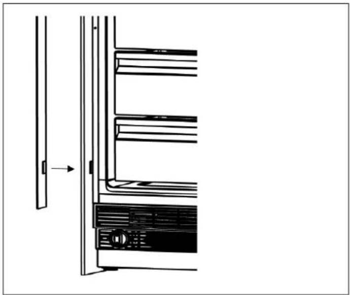
natural_image
Diagram of a refrigerator interior showing front and side views with no text or symbolsFig. 104
natural_image
Technical line drawing of a mechanical device with internal components and mounting brackets (no text or symbols)Fig. 105
natural_image
Technical line drawing of a cabinet or rack structure with mounting brackets and structural elements (no text or symbols)Fig. 106
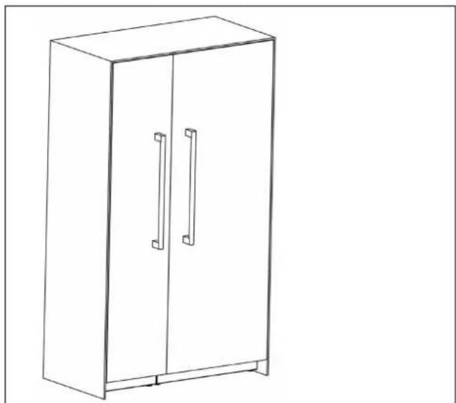
natural_image
Line drawing of a two-decker cabinet with two doors and two handles (no text or symbols)Fig. 107
BERICHT VAN ONZE VOORZITTER
natural_image
Technical diagram of a mechanical assembly with dimension lines (no text or symbols)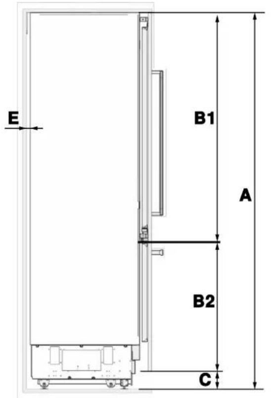
Afb. 4
| A B C D E F G H | ||||||
| 2134 mm(84") | 2030 mm(79 15/16") | 101 mm (4") 3 mm (1/8") | Remainingspace afterinstallation:19 mm (3/4") | 2 mm (1/16") | 574 mm(22 5/8") | 42 mm(1 5/8") |
natural_image
Diagram of an open refrigerator with shelves and door, showing internal compartments and a downward arrow indicating a component (no text or symbols present)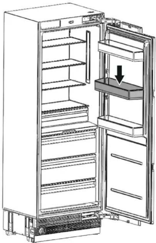
natural_image
Line drawing of an open refrigerator with a downward arrow indicating the interior portion (no text or symbols present)Afb. 5
CATEGORIE
RFZ45S5FPRS / RFZ45S5FPLS
RFZ60S5FPNS RLD60S5FPNS RLD75S5FPNS
Max. lading 10 kg (22 lbs) 15 kg (33 lbs) 15 kg (33 lbs) 15 kg (33 lbs)
AANGEPAST DEURPANEEL (VOOR MODELLEN DIE MET PANELEN KUNNEN WORDEN BEKLEED)
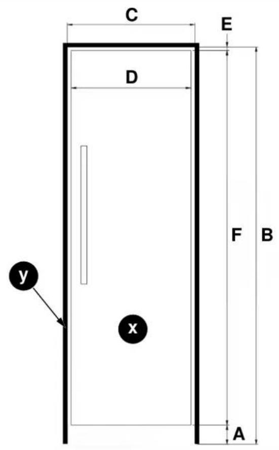
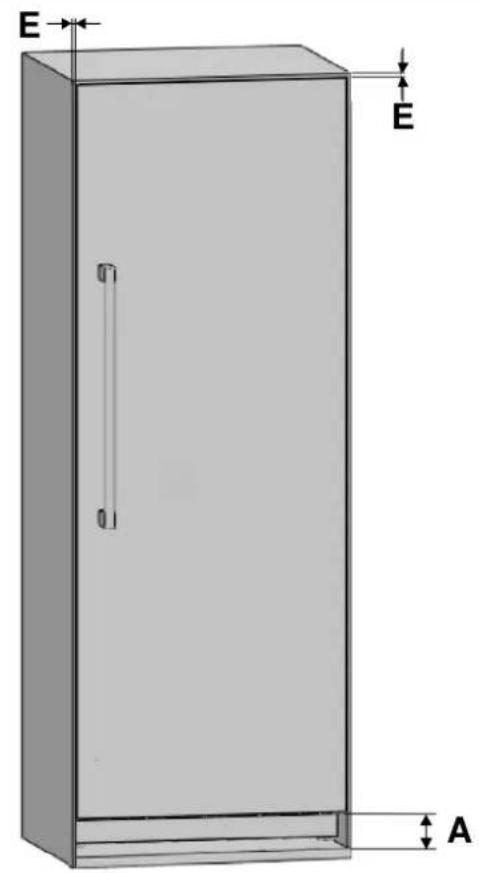
Afb. 6
• x: HOUTEN DEURPANEEL
· y: HOUTEN KAST
natural_image
3D line drawing of a cabinet with open door and internal panel (no text or symbols)Afb. 9

WAARSCHUWING
Afb. 10
Afb. 11
UITPAKKEN

WAARSCHUWING
natural_image
3D architectural rendering of a rectangular building with vertical supports and horizontal beams (no text or symbols)Afb. 12
natural_image
Exploded view diagram of a refrigerator internal structure, showing compartments and casing (no text or labels)Afb. 13

OPGELET
natural_image
Technical diagram of a mechanical device with internal components and directional arrows indicating flow or movement (no text or symbols present)Afb. 16
MONTAGE VAN MUURBEUGELS

WAARSCHUWING
natural_image
Three black-and-white icons: a hammer, a nail, and a glove, arranged in rounded squares (no text or symbols)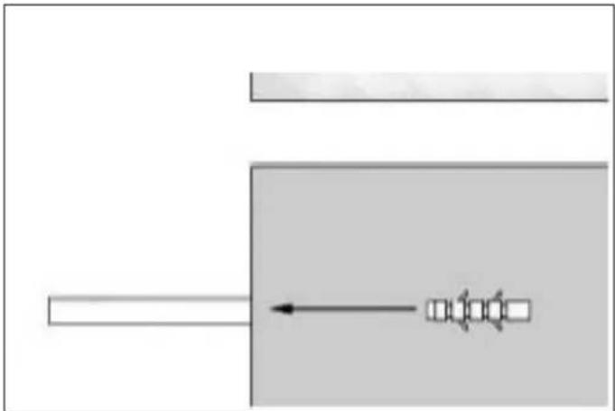
natural_image
Pure diagram of a mechanical or electrical component with no text, numbers, or symbolsAfb. 19
natural_image
Technical diagram of a mechanical assembly with circular component and mounting base (no visible text or symbols)Afb. 24
natural_image
Diagram showing a mechanical device with a bracket and a vertical panel, no text or symbols presentAfb. 25

OPMERKING
natural_image
Technical illustration of a server rack with zoomed-in views showing internal components (no text or symbols)Afb. 26

OPMERKING
Afb. 29
A/D –Draai de stelstang rechtsom om de voorkant te heffen
B/C –Draai de stelstang rechtsom om de achterkant te heffen
natural_image
Interior view of a mechanical or electrical enclosure with internal components and no visible text or symbolsAfb. 30
natural_image
Technical line drawing of a cabinet or enclosure with internal structural lines and a magnified inset showing internal components (no text or symbols)Afb. 31
natural_image
Technical line drawing of a refrigerator internal structure with an inset showing a close-up of the front panel (no text or symbols present)Afb. 34

OPMERKING
natural_image
Interior view of a refrigerator showing open doors, shelves, and internal compartments (no text or labels)Afb. 35
BEVESTIGING VAN DE BOVENSTE BEUGEL
natural_image
Line drawing of a refrigerator interior showing front and rear compartments (no text or symbols)Afb. 36
DE ONDERKAST INSTALLEREN
natural_image
Technical diagram of an industrial machine with labeled component A, showing internal wiring and housing (no text or symbols beyond label)Afb. 37
natural_image
Technical illustration of an industrial machine with visible internal components and mounting brackets (no text or symbols)Afb. 38
HET LUCHTROOSTER BEVESTIGEN
natural_image
Technical diagram of a refrigerant unit with internal airflow path and ventilation grilles (no text or labels)Afb. 39

OPMERKING
natural_image
Technical line drawing of a door panel and shelf assembly (no text or symbols)Afb. 40
natural_image
Line drawing of a front view of a computer rack with ventilation slots and a door (no text or symbols)Afb. 41
INSTALLATIE EN VOORBEREIDING BEDEKKINGSPANEEEL
natural_image
3D mechanical assembly diagram showing a bracket with mounting holes and a small pin (no text or symbols)Afb. 43
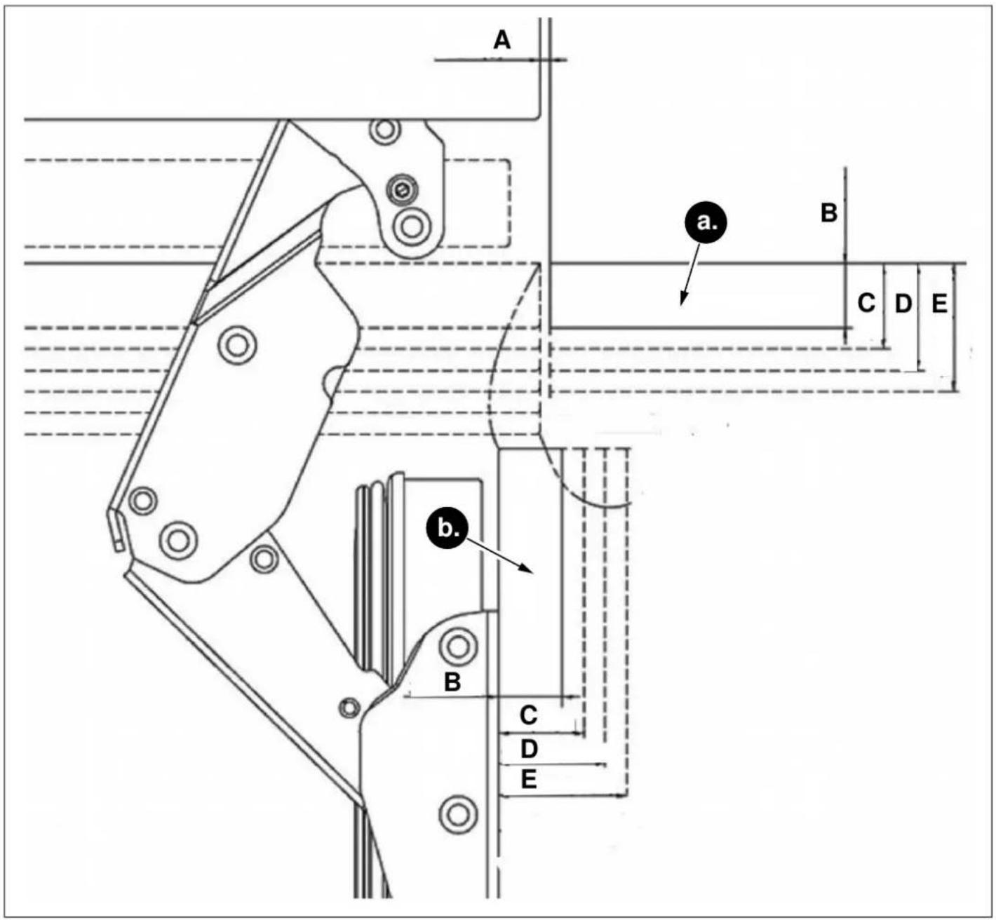
Afb. 44
a. Voorzijde kast
b. Voorpaneel
A. 3 mm (1/8")
B. 19 mm (3/4")
C. 24 mm (15/16")
D. 32 mm (1 1/4")
E. 38 mm (1 1/2")
DE BEDEKKINGEN VAN DE MECHANISMEN VAN BEDEKKINGSPANELN VERWIJDEREN
natural_image
Technical diagram of a door frame assembly with mounting bracket and internal components (no text or symbols)natural_image
Technical diagram showing a mounted device with mounting brackets and a separate panel, no text or symbols presentAfb. 47
Afb. 45 RFZ45S5FPRS / RFZ45S5FPLS RFZ60S5FPNS
RLD60S5FPNS
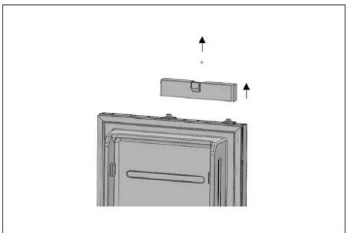
natural_image
Diagram of a refrigerator interior showing front panel, door, and side shelf with upward arrows indicating movement (no text or symbols)Afb. 46 RLD75S5FPNS

WAARSCHUWING
natural_image
Technical illustration of an open refrigerator with visible door, shelves, and cooling unit (no text or labels)Afb. 48 RFZ45S5FPRS / RFZ45S5FPLS
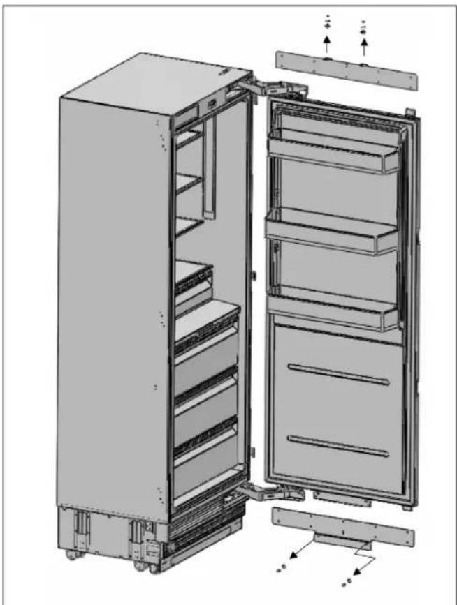
natural_image
Technical illustration of an open refrigerator with visible door, shelves, and cooling unit (no text or labels)Afb. 49 RFZ60S5FPNS RLD60S5FPNS RLD75S5FPNS
DE BEDEKKINGSPANELN VOORBEREIDEN

OPMERKING
natural_image
Diagram showing a rotating mechanical component with two plates and directional arrows indicating rotation (no text or symbols)Afb. 50
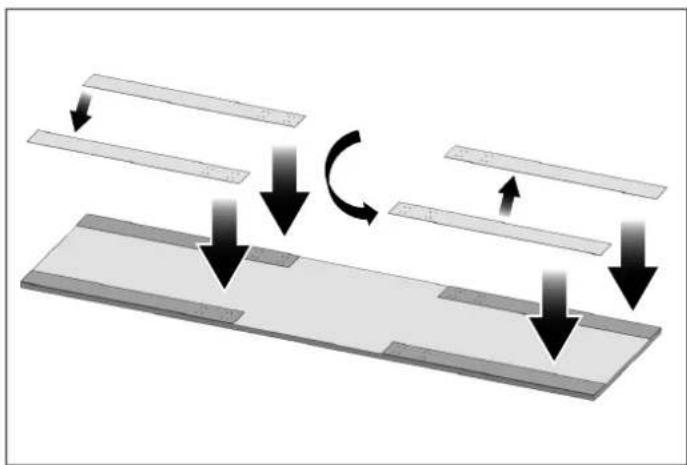
natural_image
Diagram showing a mechanical or structural assembly with downward arrows indicating motion, no text or symbols present.Afb. 51
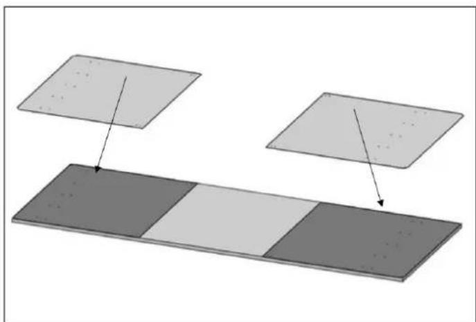
natural_image
Diagram showing two rectangular panels with arrows pointing to a central dark panel, no text or symbols presentAfb. 52

WAARSCHUWING
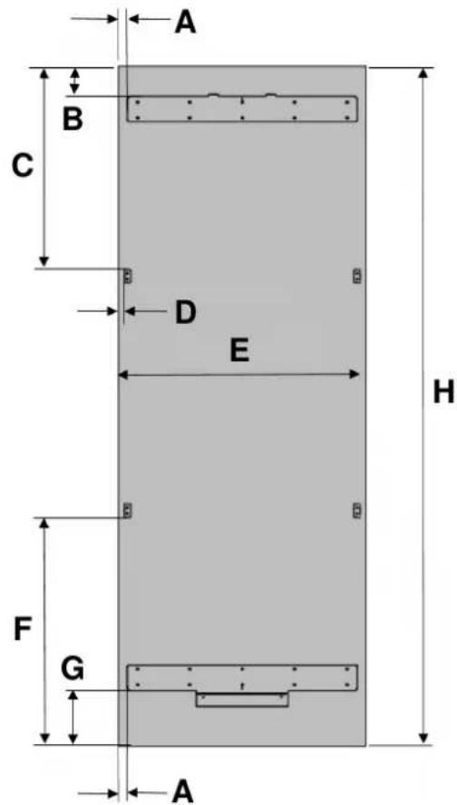
Afb. 53 RFZ45S5FPRS / RFZ45S5FPLS Afb. 54 RFZ60S5FPNS RLD60S5FPNS RLD75S5FPNS
| CATEGORIE | RFZ45S5FPRS / RFZ45S5FPLS | RFZ60S5FPNS RLD60S5FPNS RLD75S5FPNS |
| A | 10 mm (3/8") 10 mm (3/8") 10 mm (3/8") 10 mm (3/8") | |
| B | 85 mm (3 3/8") | |
| C | 595,5 mm (23 7/16") | |
| D | 18,2 mm (7/10") | |
| E | 451 mm (17 3/4") 603 mm (23 3/4") 603 mm (23 3/4") 756 mm (29 3/4") | |
| F | 693,5 mm (27 5/16") | |
| G | 175 mm (6 7/8") | |
| H | 2030 mm (79 15/16") | |

WAARSCHUWING
Afb. 56 RFZ60S5FPNS RLD60S5FPNS RLD75S5FPNS
natural_image
Simple line drawing of a mechanical setup with a piston and lever, no text or symbols presentAfb. 57 RFZ45S5FPRS / RFZ45S5FPLS

WAARSCHUWING
natural_image
Diagram of a mechanical device with a curved arrow indicating motion or force (no text or symbols)Afb. 58
HET BOVENSTE DEEL VAN HET AANGEPASTE DEURPANEEL MET BOUTEN UITLIJNEN
Afb. 59 RFZ60S5FPNS RLD60S5FPNS RLD75S5FPNS
natural_image
Technical line drawing of a door frame with two horizontal bars and circular annotations indicating measurement points (no text or symbols present)Afb. 60
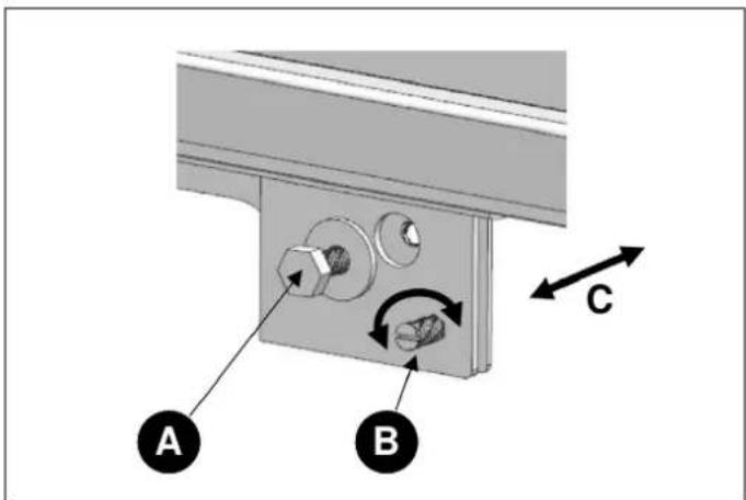
Afb. 61
natural_image
Three icons: a tool, a screwdriver, and a hammer, each enclosed in rounded squares (no text or symbols)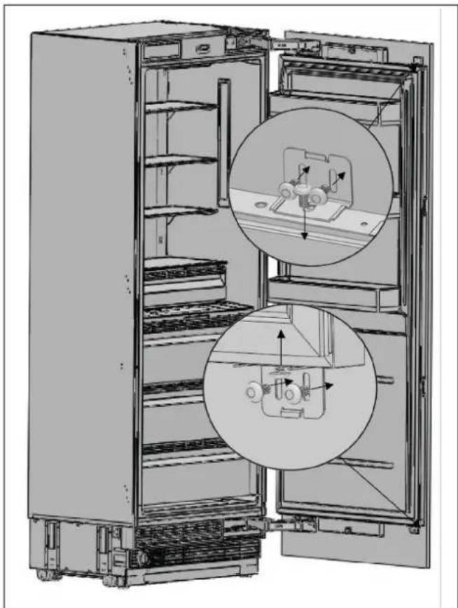
natural_image
Interior view of a refrigerator showing open doors and internal compartments with mechanical components (no text or symbols visible)Afb. 62 RFZ60S5FPNS RLD60S5FPNS RLD75S5FPNS
- Klem de afdekking op de meubeldeurbeugel vast.
Bevestig en schroef de bovenste/onderste sierafdekkingen vast.
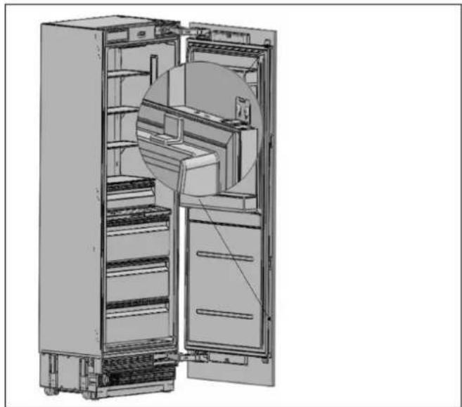
natural_image
Interior view of a refrigerator showing open doors, shelves, and a close-up of the door (no text or symbols visible)Afb. 63 RFZ60S5FPNS RLD60S5FPNS RLD75S5FPNS
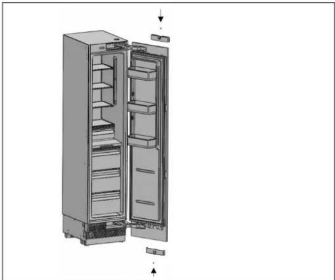
natural_image
Exploded view diagram of a refrigerator showing internal compartments and doorways (no text or labels)Afb. 64 RFZ45S5FPRS / RFZ45S5FPLS
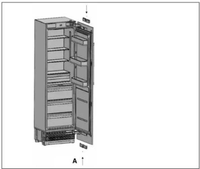
natural_image
3D diagram of a refrigerator interior showing open doors and internal shelves (no text or labels)Afb. 65 RFZ60S5FPNS RLD60S5FPNS
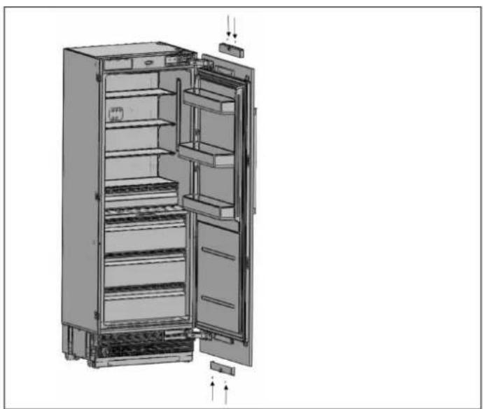
natural_image
3D diagram of an open refrigerator with visible door, shelves, and cooling unit (no text or labels)Afb. 66 RLD75S5FPNS

WAARSCHUWING
natural_image
Technical diagram of a multi-panel refrigerator with an inset showing a close-up view of the front panel (no text or symbols present)Afb. 67
natural_image
Technical line drawing of a mechanical part with a bracket and a separate view labeled A (no text or symbols present)Afb. 68
A Dubbel tape
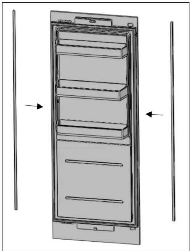
natural_image
Technical line drawing of a multi-tiered storage cabinet with two vertical supports and an arrow indicating direction (no text or symbols)Afb. 69
AFSTELLEN VAN SCHARNIEREN EN OMKEREN VAN DEUROPENING
DE VEERSPANNING VAN DE SCHARNIEREN AFSTELLEN
natural_image
Technical illustration of an open refrigerator with a circular inset showing internal components (no text or symbols)Afb. 70

WAARSCHUWING
natural_image
Technical line drawing of an open refrigerator with a circular inset showing internal components (no text or symbols)Afb. 71
natural_image
Diagram of a door with an open lid and a handle, showing a mechanical assembly (no text or symbols)Afb. 73 RFZ45S5FPRS / RFZ45S5FPLS

OPGELET
natural_image
Technical diagram of a door frame with two vertical supports and horizontal bars, no text or symbols presentAfb. 72
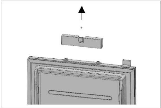
natural_image
3D technical diagram of a mechanical assembly with an upward arrow indicating force or direction (no text or symbols present)Afb. 74 RFZ60S5FPNS RLD60S5FPNS
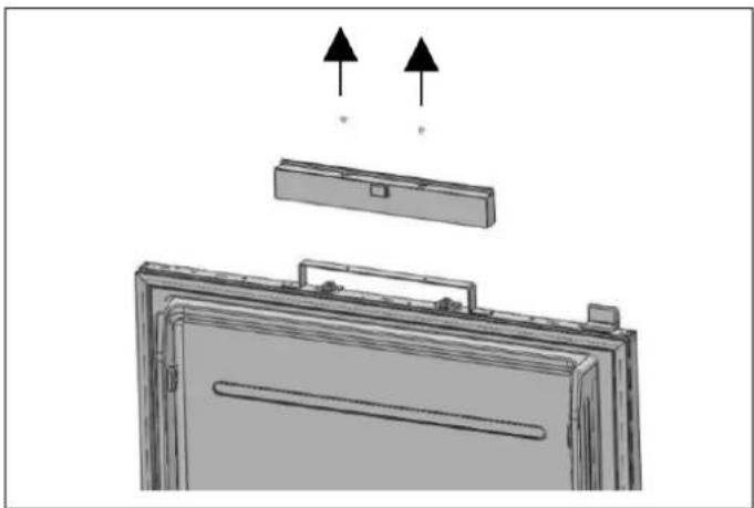
natural_image
Diagram of a door frame with two arrows indicating upward motion (no text or symbols)Afb. 75 RLD75S5FPNS
natural_image
Diagram showing a monitor mounted on a wall with a separate panel and a downward arrow indicating motion (no text or symbols)Afb. 76 RFZ45S5FPRS / RFZ45S5FPLS
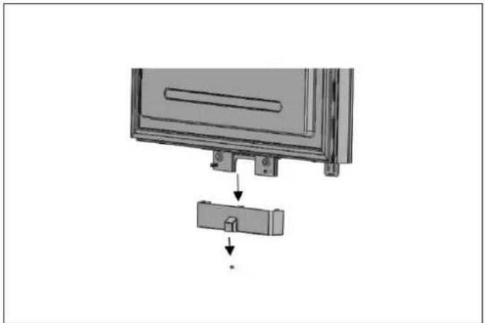
natural_image
Diagram showing a device with a lock and a separate component, no text or symbols presentAfb. 77 RFZ60S5FPNS RLD60S5FPNS

natural_image
Diagram of a monitor with an attached cable and two arrows indicating downward motion (no text or symbols)Afb. 78 RLD75S5FPNS
natural_image
Interior view of a refrigerator with open doors and shelves (no text or symbols visible)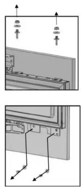
natural_image
Technical diagram showing two views of a mechanical assembly with arrows indicating direction (no text or symbols present)Afb. 79 RFZ45S5FPRS / RFZ45S5FPLS
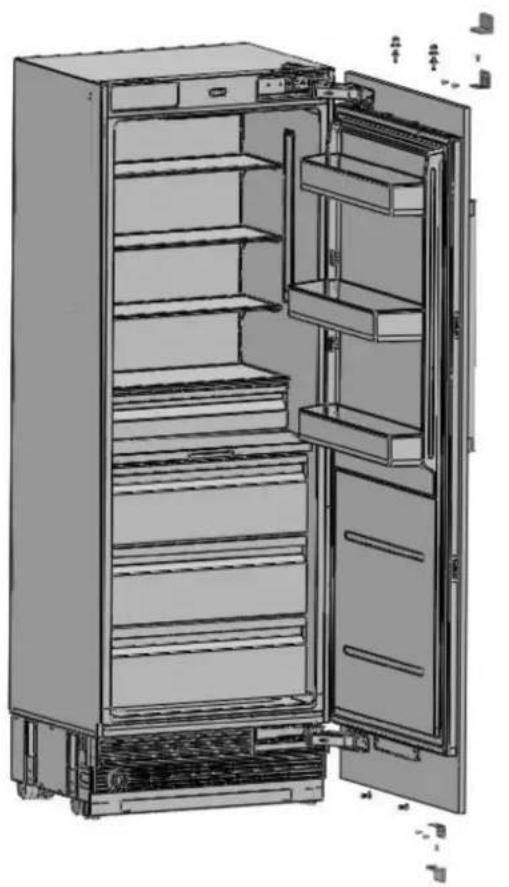
natural_image
Interior view of a refrigerator showing open doors, shelves, and storage compartments (no text or labels visible)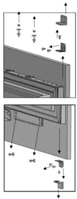
Afb. 80 RFZ60S5FPNS RLD60S5FPNS RLD75S5FPNS
natural_image
Technical diagram of an open electrical cabinet with internal components and a magnified inset showing internal wiring (no text or symbols present)Afb. 81
natural_image
Technical line drawing of a rectangular enclosure with horizontal and diagonal lines indicating internal structure (no text or symbols)Afb. 82
DE SCHARNIEREN VERVANGEN
natural_image
Illustration of a multi-tier refrigerator with an inset close-up showing the interior panel (no text or symbols visible)Afb. 83
natural_image
3D line drawing of a refrigerator cabinet with shelves and doors (no text or symbols)Afb. 84
OMKEREN RICHTING BOVENSTE DEEL LUCHTROOSTER
natural_image
Technical illustration of a mechanical device showing front and side views of a chamber with ventilation grilles (no text or symbols)Afb. 85
DE RICHTING VAN HET BOVENSTE DEEL VAN HET LUCHTROOSTER OMKEREN
Afb. 87
• C Scharnier links luchtrooster
• D Draai de luchtroosterafdekking 180°
natural_image
3D rendering of a multi-tiered refrigerator cabinet with visible shelves and doorways (no text or labels)Afb. 88
natural_image
Diagram of a multi-tiered refrigerator with an open door and internal compartments, showing no text or symbols.Afb. 89
DE DEUR TERUGPLAATSEN
natural_image
Diagram of an open refrigerator with internal components and a magnified inset showing internal wiring (no text or symbols)Afb. 90
flowchart
graph TD
    1["1"] --> A["Square component"]
    2["2"] --> A
    3["3"] --> B["Head and nut"]
    4["4"] --> C["Grid-like structure"]
    5["5"] --> D["Arrow pointing left"]
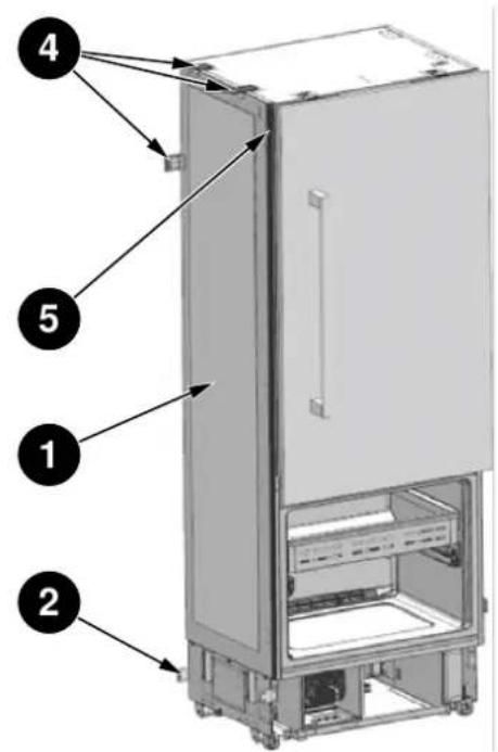
Afb. 94
NR. ONDERDEELNAAM SPEC AANT.
| 1 Isolatieschuim | Spons, grijs, T3.0*400*1750 | 1 |
| 2 | Onderste beugel T2.0, Cr+zn-coating | 1 |
| 3 Schroeven M4*12 | 16 | |
| 4 | Bovenste beugels POM | 3 |
| 5 | Centrale afwerking Extrusie PVC L=1876 | 1 |
DE BOVENSTE EN ONDERSTE BEUGELS INSTALLEREN
Afb. 95
natural_image
Line drawing of two rectangular cabinets with one open and one closed, showing internal components and a magnified inset (no text or symbols)Afb. 96
natural_image
Line drawing of a two-door refrigerator with an inset showing a close-up of the front panel (no text or symbols present)Afb. 97
natural_image
Technical line drawing of a cabinet or enclosure with mounting holes and internal components, showing close-up insets (no text or symbols)Afb. 98
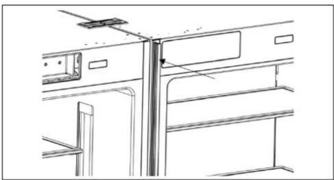
natural_image
Technical line drawing of a cabinet or enclosure structure with mounting brackets and structural beams (no text or symbols)natural_image
Line drawing of a two-door refrigerator with handlebars and side-mounted doors, showing internal structure and mounting points (no text or symbols)Afb. 99
DE KOELKASTEN WATERPAS PLAATSEN
Afb. 100
natural_image
Line drawing of an open refrigerator with shelves and doors open, showing internal compartments and ventilation slots (no text or labels)Afb. 101
DE VERBINDINGSBEUGELS OP DE BOVENZIJDE VAN DE KOELKAST INSTALLEREN
natural_image
Technical line drawing of an open refrigerator with internal compartments and a hanging tool (no text or symbols)Afb. 102
DE BOVENSTE EN ZIJAFWERKINGEN INSTALLEREN
natural_image
Technical line drawing of a refrigerator interior with shelves and doors, showing structural components (no text or symbols)Afb. 103
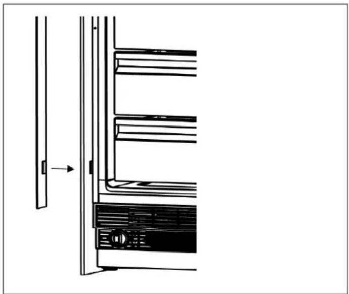
natural_image
Diagram of a refrigerator interior showing front and side views with no text or symbolsAfb. 104
natural_image
Technical line drawing of a mechanical device with internal components and mounting brackets (no text or symbols)Afb. 105
natural_image
Technical line drawing of a cabinet or rack structure with mounting brackets and structural elements (no text or symbols)Afb. 106
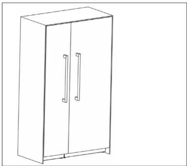
natural_image
Line drawing of a two-decker cabinet with two doors and two handles (no text or symbols)Afb. 107
FRÅN CHEFENS SKRIVBORD
natural_image
Technical diagram of a mechanical assembly with dimension lines (no text or symbols)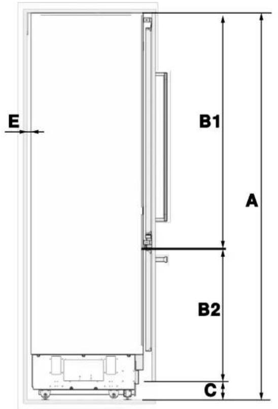
Fig. 4
A B C D E F G H
| 2134 mm(84") | 2030 mm(79 15/16") | 101 mm (4") 3 mm (1/8") |
Remaining
| space after installation: | 2 mm (1/16") | 574 mm(22 5/8") | 42 mm(1 5/8") |
19 mm (3/4")
PLATS FÖR TIPPSKYDDSFÄSTE
| IJK | |
| 2134 mm (84") 4 mm (5/32") | 2130 mm (83 7/8") |
MINSTA HÖJDJUSTERING FÖR NIVELLERING
| L | |
| Fram | 8 mm (5/16") |
| Bak | 7 mm (1/4") |
DÖRRFACKENS LASTKAPACITET FÖR LIVSMEDEL
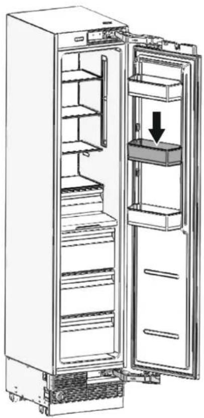
natural_image
Diagram of an open refrigerator with shelves and door, showing internal compartments and a downward arrow indicating a component (no text or symbols present)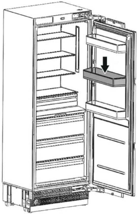
natural_image
Line drawing of an open refrigerator with a downward arrow indicating the interior portion (no text or symbols present)Fig. 5
KATEGORI
RFZ45S5FPRS / RFZ45S5FPLS
RFZ60S5FPNS RLD60S5FPNS RLD75S5FPNS
Max. last
10 kg (22 lbs) 15 kg (33 lbs) 15 kg (33 lbs) 15 kg (33 lbs)
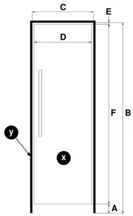
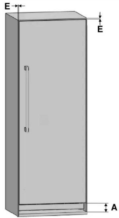
Fig. 6
• x: DÖRRPANEL AV TRÄ
y: TRÄSKÅP
natural_image
3D technical line drawing of a cabinet or enclosure with no visible text, numbers, or symbolsFig. 9

WARNING
Fig. 10
Fig. 11
UPPACKNING

WARNING
natural_image
3D architectural rendering of a rectangular building facade with vertical supports and horizontal beams (no text or symbols)Fig. 12
natural_image
Exploded view diagram of a refrigerator internal structure (no text or labels)Fig. 13

OBSERVERA
natural_image
Technical diagram of an air conditioner unit with cooling fins and ventilation slots (no text or labels)Fig. 16
MONTERA TIPPSKYDDSFÄSTENA

WARNING
natural_image
Three black-and-white icons: a hammer, a rifle, and a glove, arranged horizontally (no text or symbols)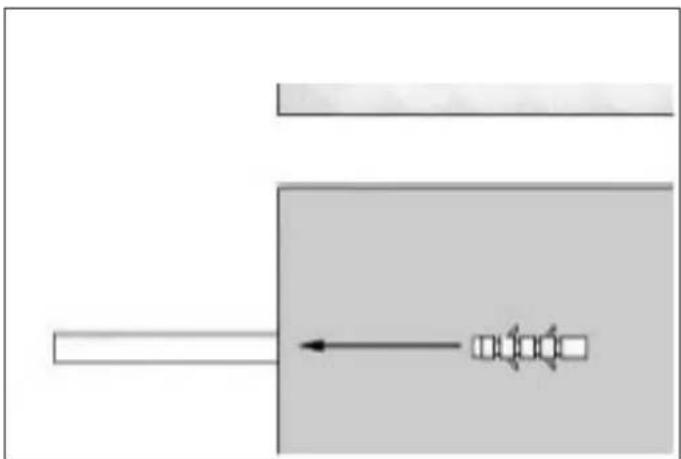
natural_image
Pure diagram of a mechanical or electrical component with no text, numbers, or symbolsFig. 19
natural_image
Technical diagram of a mechanical assembly with circular component and mounting base (no visible text or symbols)Fig. 24
natural_image
Diagram showing a mechanical device with a bracket and a vertical panel, no text or symbols presentFig. 25

ANMÄRKNING
natural_image
Technical illustration of a server rack with zoomed-in views showing internal components (no text or symbols)Fig. 26

ANMÄRKNING
Fig. 29
natural_image
Interior view of a server rack unit with open door, internal compartments, and visible wiring (no text or labels)Fig. 30
natural_image
Technical line drawing of a cabinet or enclosure with internal components and a magnified inset showing cross-section details (no text or symbols)Fig. 31
natural_image
Technical line drawing of a refrigerator internal structure with an inset showing a close-up of the front panel (no text or symbols present)Fig. 34

ANMÄRKNING
natural_image
Interior view of a refrigerator showing open doors, shelves, and internal compartments (no text or labels visible)Fig. 35
SÄKRA DET ÖVRE FÄSTET
natural_image
Line drawing of a cabinet interior showing front and rear compartments with no text or symbolsFig. 36
INSTALLERA DET UNDRE SKÅPET
natural_image
Technical diagram of an industrial machine with labeled component A, showing internal components and wiring (no readable text or symbols)Fig. 37
natural_image
Technical illustration of an industrial machine with internal components and wiring (no visible text or symbols)Fig. 38
MONTERA LUFTVENTILATIONSGALLRET
natural_image
Technical diagram of an air conditioner unit with cooling fins and ventilation slots (no text or labels)Fig. 39
FÄSTA DEKORATIONSLISTER
natural_image
Technical line drawing of a door panel and interior enclosure (no text or symbols)Fig. 40

ANMÄRKNING
natural_image
Line drawing of a front view of a computer monitor with an open lid and drive bays (no text or symbols)Fig. 41
INSTALLATION OCH FÖRBEREDELSE AV ÖVERLÄGGSPANEL
VÄLJA TJOCKLEK PÅ DÖRREN
natural_image
3D mechanical assembly diagram showing a bracket with mounting holes and a small pin (no text or symbols)Fig. 43
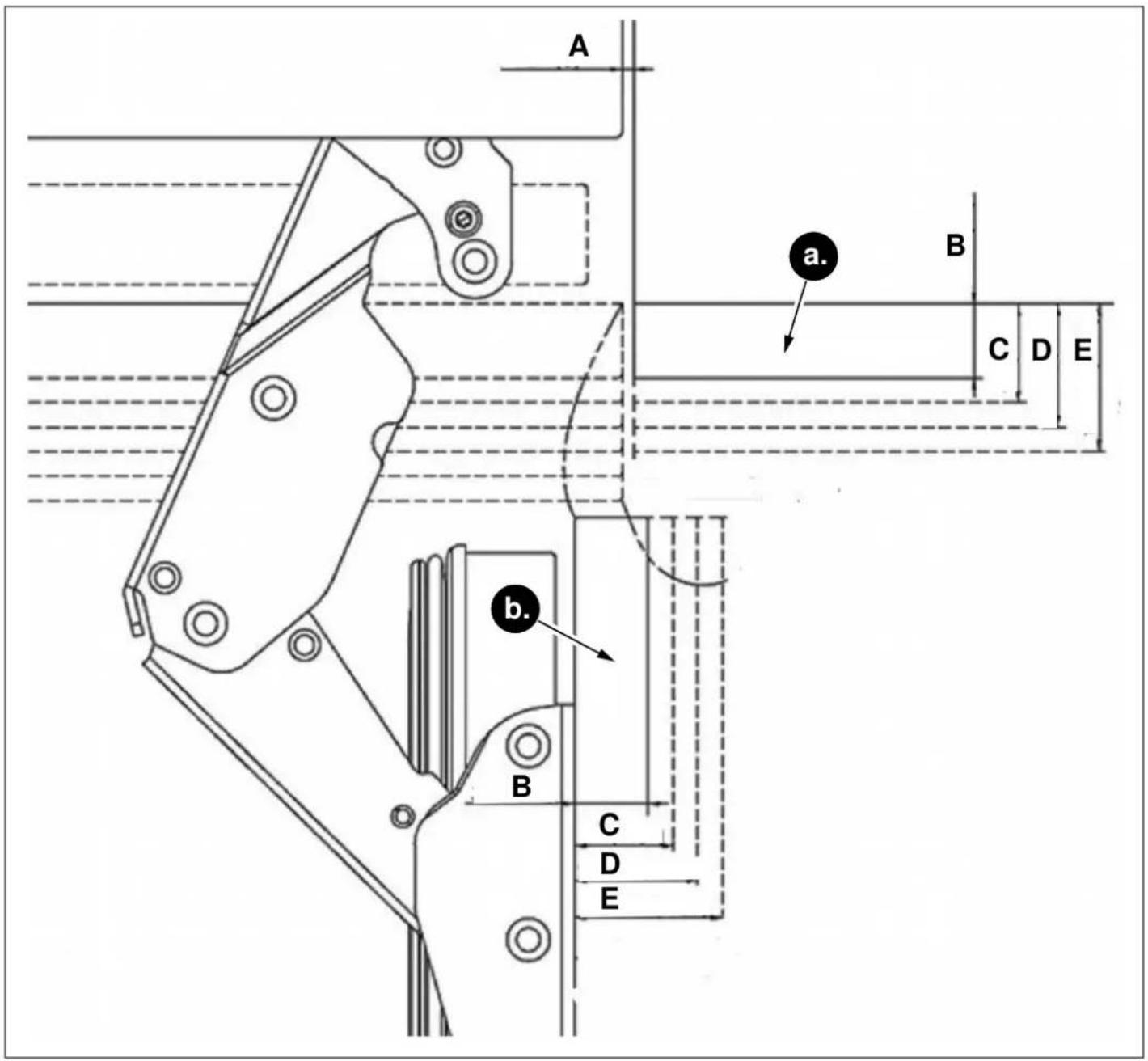
Fig. 44
natural_image
Technical diagram of a door frame assembly with mounting bracket and control panel (no text or symbols)natural_image
Technical diagram showing a mounted device with mounting brackets and a bracket, no text or symbols presentFig. 47
Fig. 45 RFZ45S5FPRS / RFZ45S5FPLS RFZ60S5FPNS
RLD60S5FPNS
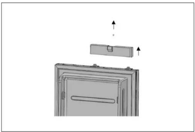
natural_image
Diagram of a refrigerator interior showing front panel, door, and side shelf with upward arrows indicating movement (no text or symbols)Fig. 46 RLD75S5FPNS

WARNING
natural_image
Exploded view diagram of an open refrigerator showing internal compartments and doorways (no text or labels)Fig. 48 RFZ45S5FPRS / RFZ45S5FPLS
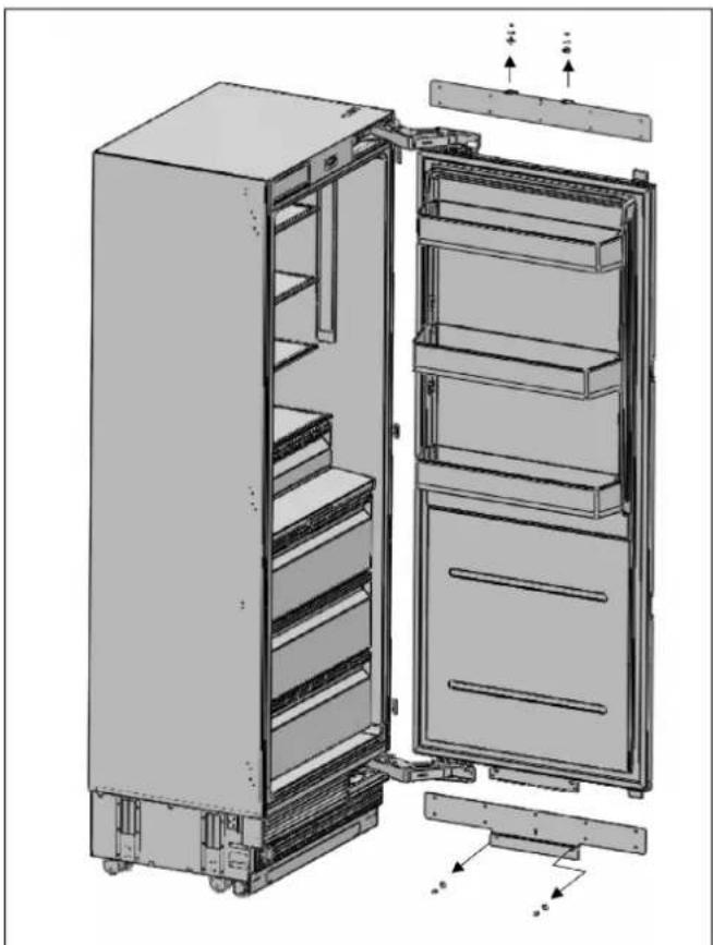
natural_image
Technical illustration of an open refrigerator with visible door, shelves, and cooling unit (no text or labels)Fig. 49 RFZ60S5FPNS RLD60S5FPNS RLD75S5FPNS
natural_image
Diagram showing a rotating mechanical component with two plates and directional arrows indicating rotation (no text or symbols)Fig. 50
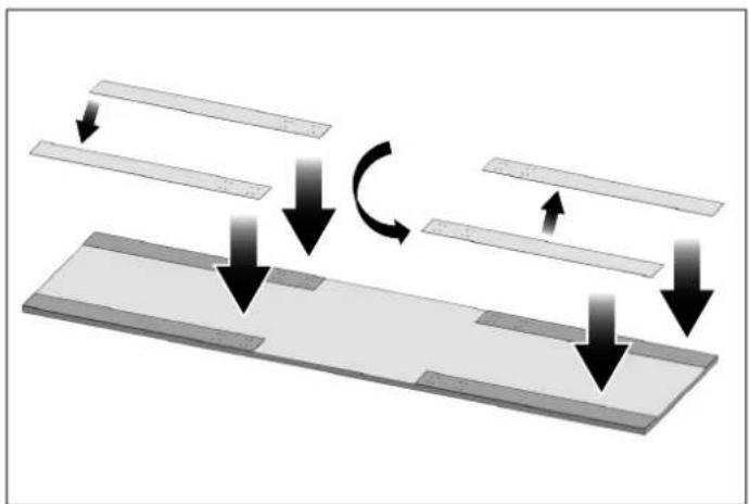
natural_image
Diagram showing a curved arrow indicating rotation or movement between two parallel strips, with no text or symbols present.Fig. 51
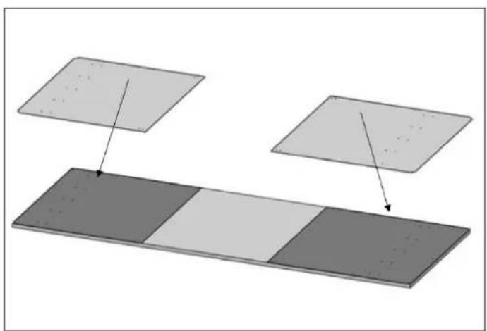
natural_image
Diagram showing two rectangular panels with different shades of gray, one above a dark panel and the other below (no text or symbols)Fig. 52

WARNING
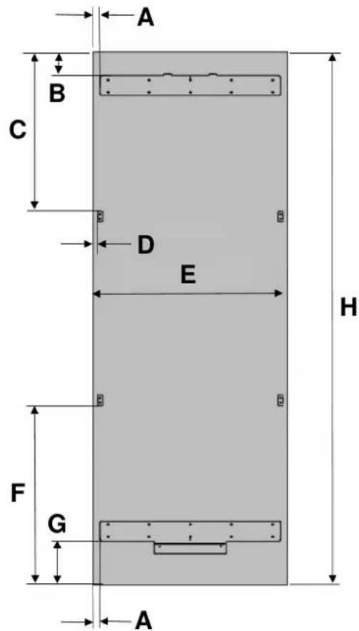
Fig. 53 RFZ45S5FPRS / RFZ45S5FPLS Fig. 54 RFZ60S5FPNS RLD60S5FPNS RLD75S5FPNS
| KATEGORI | RFZ45S5FPRS / RFZ45S5FPLS | RFZ60S5FPNS RLD60S5FPNS RLD75S5FPNS |
| A | 10 mm (3/8") 10 mm (3/8") 10 mm (3/8") 10 mm (3/8") | |
| B | 85 mm (3 3/8") | |
| C | 595,5 mm (23 7/16") | |
| D | 18,2 mm (7/10") | |
| E | 451 mm (17 3/4") 603 mm (23 3/4") 603 mm (23 3/4") 756 mm (29 3/4") | |
| F | 693,5 mm (27 5/16") | |
| G | 175 mm (6 7/8") | |
| H | 2030 mm (79 15/16") | |

WARNING
Fig. 56 RFZ60S5FPNS RLD60S5FPNS RLD75S5FPNS
natural_image
Simple line drawing of a mechanical setup with a piston and lever, no text or symbols presentFig. 57 RFZ45S5FPRS / RFZ45S5FPLS

WARNING
natural_image
Technical line drawing of a mechanical component with a curved arrow indicating rotation (no text or symbols)Fig. 58
INRIKTA DEN ÖVRE DELEN AV ANPASSAD DÖRRPANEL MED BULTAR
Fig. 59 RFZ60S5FPNS RLD60S5FPNS RLD75S5FPNS
natural_image
Technical line drawing of a door frame with two horizontal bars and circular annotations indicating measurement points (no text or symbols present)Fig. 60
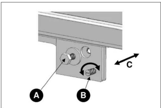
Fig. 61
natural_image
Technical illustration of an open refrigerator showing internal components and a close-up view of the interior (no text or symbols present)Fig. 62 RFZ60S5FPNS RLD60S5FPNS RLD75S5FPNS
natural_image
Interior view of a refrigerator showing open doors, shelves, and a close-up of the door (no text or symbols visible)Fig. 63 RFZ60S5FPNS RLD60S5FPNS
RLD75S5FPNS
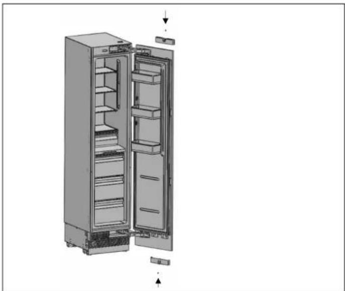
natural_image
Exploded view diagram of an open refrigerator showing internal compartments and doorways (no text or labels)Fig. 64 RFZ45S5FPRS / RFZ45S5FPLS
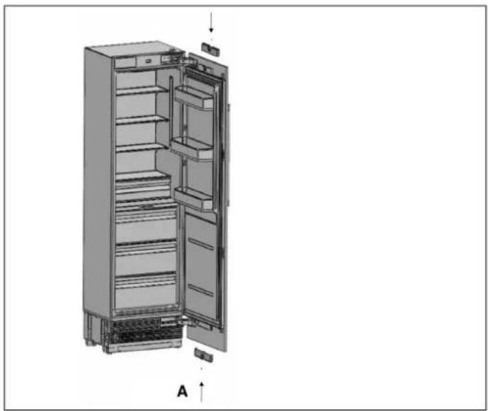
natural_image
3D diagram of a refrigerator interior showing open doors and internal shelves (no text or labels)Fig. 65 RFZ60S5FPNS RLD60S5FPNS
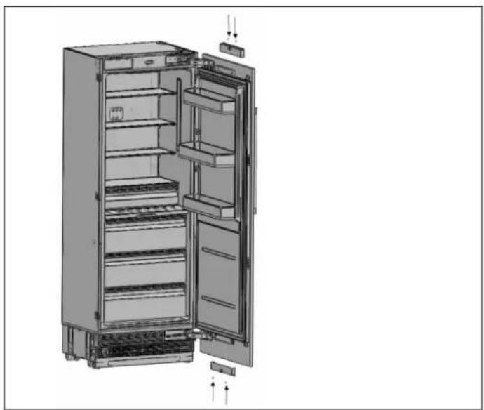
natural_image
3D rendering of an open refrigerator with visible door, shelves, and cooling unit (no text or symbols)Fig. 66 RLD75S5FPNS
natural_image
Technical diagram of a multi-panel refrigerator with an inset showing a close-up view of the front panel (no text or symbols present)Fig. 67

WARNING
natural_image
Technical line drawing of a mechanical part with a labeled section A (no text or symbols present)Fig. 68
A Dubbeltejp
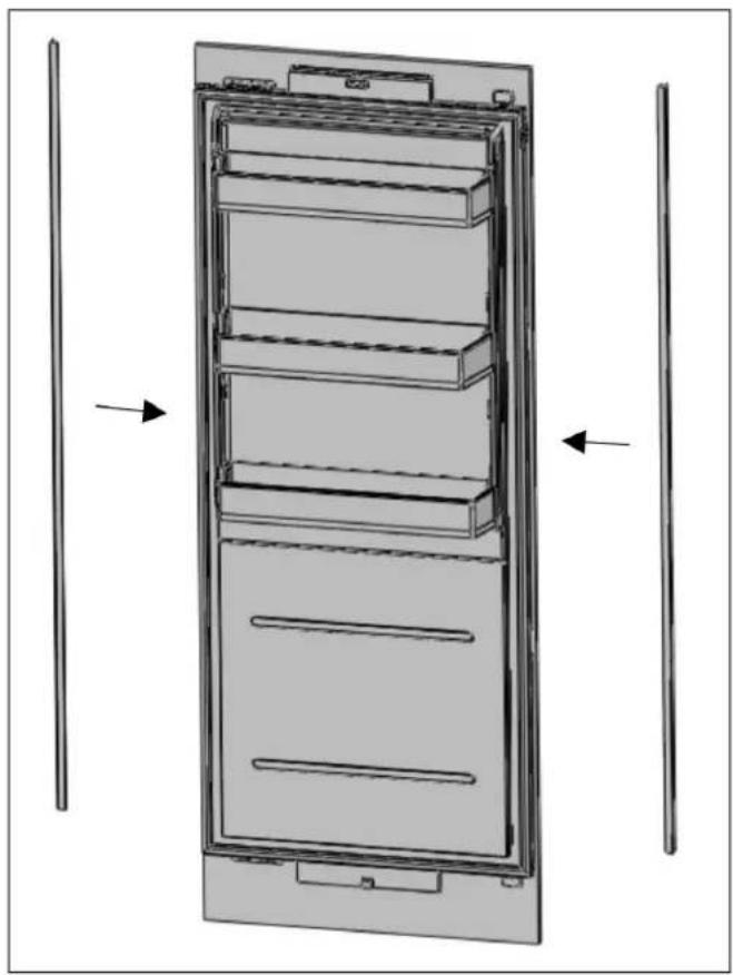
natural_image
Technical line drawing of a multi-tiered refrigerator with two vertical supports and an arrow indicating direction (no text or symbols)Fig. 69
GÅNGJÄRNSJUSTERING OCH OMHÄNGNING AV DÖRR
JUSTERA FJÄDERSPÄNNINGEN PÅ GÅNGJÄRNEN
natural_image
Technical illustration of an open refrigerator with a circular inset showing internal components (no text or symbols)Fig. 70

WARNING
natural_image
Technical line drawing of an open refrigerator with a circular inset showing the interior portion (no text or symbols)Fig. 71

OBSERVERA
natural_image
Technical line drawing of a door frame with two vertical supports and horizontal bars, no text or symbols presentFig. 72
natural_image
3D diagram of a door with an arrow indicating upward motion, showing internal components and mounting bracket (no text or symbols)Fig. 73 RFZ45S5FPRS / RFZ45S5FPLS

natural_image
3D technical diagram of a mechanical assembly with an upward arrow indicating force or direction (no text or symbols present)Fig. 74 RFZ60S5FPNS RLD60S5FPNS
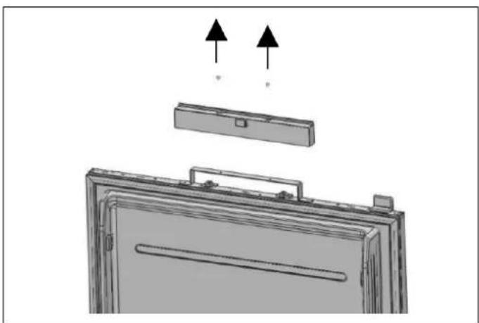
natural_image
Diagram of a device with two arrows pointing to a component, showing internal structure and mounting bracket (no text or symbols)Fig. 75 RLD75S5FPNS
natural_image
Diagram showing a monitor mounted on a wall with a separate panel and a downward arrow indicating motion (no text or symbols)Fig. 76 RFZ45S5FPRS / RFZ45S5FPLS
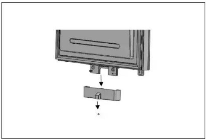
natural_image
Diagram showing a device with a lock and a separate component, no text or symbols presentFig. 77 RFZ60S5FPNS RLD60S5FPNS
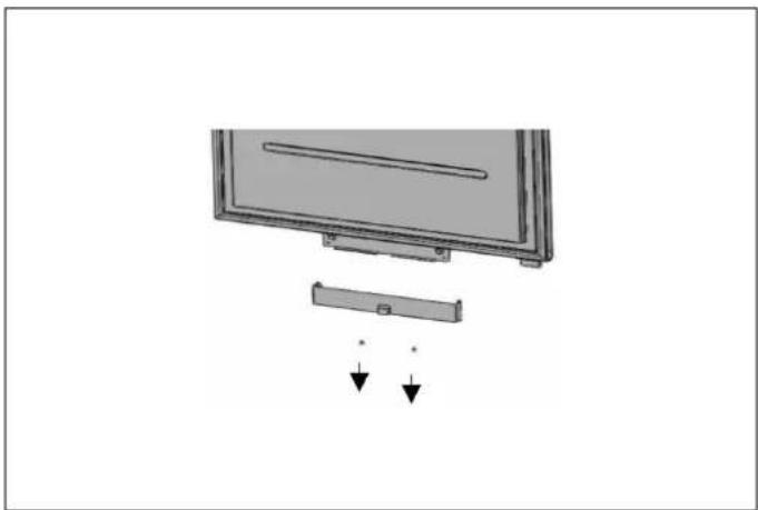
natural_image
Diagram of a monitor with a cable attachment and two arrows indicating downward motion (no text or symbols)Fig. 78 RLD75S5FPNS
natural_image
Interior view of a refrigerator with open doors and shelves (no text or symbols visible)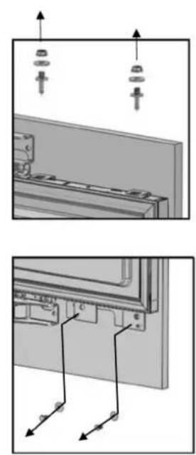
natural_image
Technical diagram showing two views of a mechanical assembly with arrows indicating direction (no text or symbols present)Fig. 79 RFZ45S5FPRS / RFZ45S5FPLS
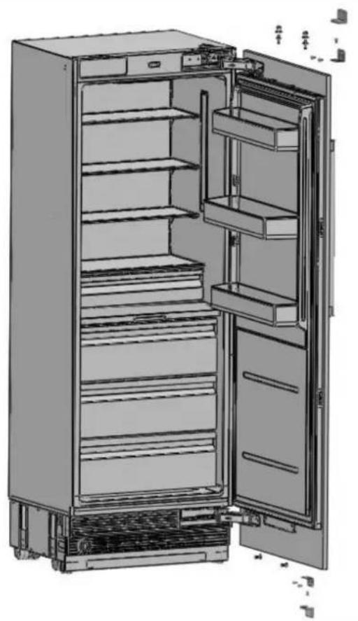
natural_image
Interior view of a fully stocked refrigerator with open doors and shelves (no text or symbols visible)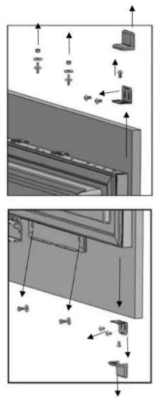
Fig. 80 RFZ60S5FPNS RLD60S5FPNS RLD75S5FPNS
AVLÄGSNA OCH FÖRBEREDA INNERDÖRREN
natural_image
Technical diagram of an open industrial cabinet with internal components and a magnified inset showing internal wiring (no text or labels)Fig. 81
natural_image
Technical line drawing of a rectangular enclosure or storage unit with internal horizontal and vertical lines, no text or symbols present.Fig. 82
BYTA UT GÅNGJÄRNEN
natural_image
Diagram of a multi-level refrigerator with an open door and internal compartments, showing no text or symbols.Fig. 83
natural_image
Technical line drawing of a multi-tier refrigerator cabinet (no text or labels visible)Fig. 84
RIKTNINGSÄNDRING AV LUFTVENTILATIONENS ÖVRE DEL
natural_image
Technical illustration of a mechanical assembly showing a component before and after assembly, with no visible text or symbols.Fig. 85
RIKTNINGSÄNDRING AV LUFTVENTILATIONENS ÖVRE DEL
Fig. 87
natural_image
3D rendering of a multi-tiered refrigerator cabinet with visible shelves and doorways (no text or labels)Fig. 88
natural_image
Diagram of a refrigerator interior showing internal compartments and a close-up of the door (no text or labels)Fig. 89
INSTALLERA DÖRREN PÅ NYTT
natural_image
Diagram of a cabinet interior showing internal components and a magnified view of the door mechanism (no text or labels)Fig. 90
flowchart
graph TD
    1["1"] --> A["Square component"]
    2["2"] --> A
    3["3"] --> B["Head and nut"]
    4["4"] --> C["Grid-like structure"]
    5["5"] --> D["Arrow pointing left"]
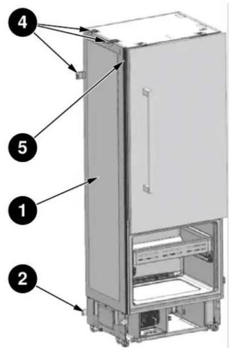
Fig. 94
NR DELENS NAMN SPEC ANTAL
| 1 | Isoleringsskum | Svamp, grå, T3.0*400*1750 | 1 |
| 2 Nedre fäste | T2.0, Cr+Zn-beläggning | 1 | |
| 3 Skruvar M4*12 | 16 | ||
| 4 | Övre fästen | POM 3 | |
| 5 | Central trim PVC extrusion L=1876 1 | ||
INSTALLERA DE ÖVRE OCH NEDRE FÄSTENA
Fig. 95
natural_image
Technical line drawing of a refrigerator with an inset close-up showing internal components (no text or symbols)Fig. 96
natural_image
Line drawing of a two-tier refrigerator with an inset showing a close-up of the front panel (no text or symbols present)Fig. 97
natural_image
Technical line drawing of a cabinet or enclosure with mounting holes and internal components, showing two views of the assembly (no text or symbols present)Fig. 98
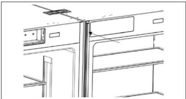
natural_image
Technical line drawing of a cabinet or enclosure with structural components (no text or symbols)natural_image
Technical line drawing of a two-door refrigerator with handlebars and doorways (no text or symbols)Fig. 99
AVVÄGA KYLSKÅPEN
Fig. 100
natural_image
Line drawing of an open refrigerator with shelves and doors open, showing internal compartments and ventilation slots (no text or labels)Fig. 101
INSTALLERA ANSLUTNINGSFÄSTENA PÅ KYLSKÅPETS ÖVRE VÄGG
natural_image
Technical line drawing of an open refrigerator with internal compartments and a handle (no text or symbols)Fig. 102
INSTALLERA DE LATERALA OCH ÖVRE TRIMNINGARNA
natural_image
Technical line drawing of a refrigerator interior with shelves and doorways (no text or symbols)Fig. 103
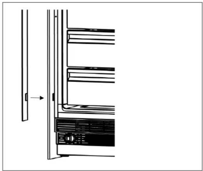
natural_image
Diagram of a refrigerator interior showing front and side views with no text or symbolsFig. 104
natural_image
Technical line drawing of a mechanical device with internal components and mounting brackets (no text or symbols)Fig. 105
natural_image
Technical line drawing of a cabinet or rack structure with mounting brackets and structural elements (no text or symbols)Fig. 106
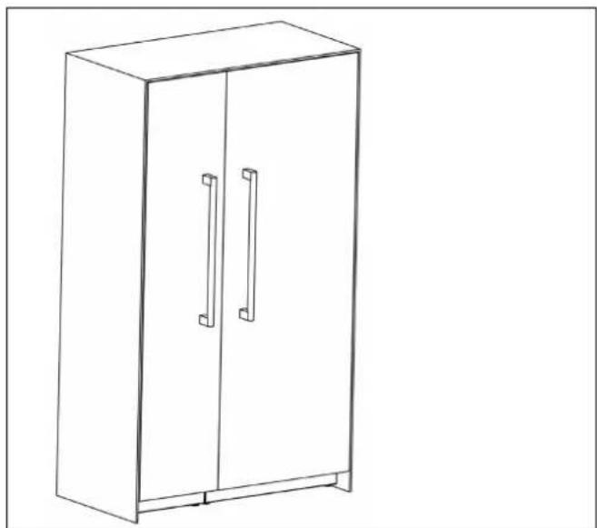
natural_image
Line drawing of a two-decker cabinet with two doors and two handles (no text or symbols)Fig. 107
www.bertazzoni.com
Via Palazzina, 8
42016 Guastalla RE
© 2025 BERTAZZONI. All rights reserved.
- FROM THE DESK OF OUR PRESIDENT
- MANUAL VALIDITY
- DANGER
- WARNING
- CAUTION
- NOTE
- SAFETY INFORMATION
- R600a refrigerant
- CARING FOR THE ENVIRONMENT
- Niche Dimensions
- FOOD LOAD BEARING CAPACITY OF THE DOOR BINS
- IMPORTANT
- TOOL LIST
- ALTERNATIVES FOR INSTALLATION
- UNPACKING
- REMOVING THE VENT HOLE ASSEMBLY
- MOUNTING THE ANTI-TIP BRACKETS
- Alternative anti-tip method:
- PREPARING THE WATER HOSE AND THE ELECTRICAL CONNECTION
- INSTALLATION IN THE CABINET
- Adjusting the refrigerator based on the cabinet niche.
- SCREWING IN THE SIDE BRACKETS
- SECURING THE UPPER BRACKET
- INSTALLING THE BOTTOM CABINET
- Complete the water connection
- ATTACHING THE AIR VENT GRILLE
- ATTACHING THE DECORATIVE TRIM COVERS
- OVERLAY PANEL INSTALLATION AND PREPARATION
- CHOOSING THE DOOR THICKNESS
- REMOVING THE OVERLAY PANEL MECHANISM COVERS
- REMOVING THE PANEL BRACKETS
- PREPARING THE OVERLAY PANELS
- INSTALLING THE OVERLAY PANELS
- HINGE ADJUSTMENT AND REVERSING THE DOOR SWING
- ADJUSTING THE SPRING TENSION OF THE HINGES
- REMOVING THE DOOR PANEL
- REMOVING AND PREPARING THE INNER DOOR
- REPLACING THE HINGES
- AIR VENT UPPER PART DIRECTION CHANGE
- HOW TO CHANGE AIR VENT UPPER PART DIRECTION
- REINSTALLING THE DOOR
- CABINET CUTOUT DIMENSIONS
- LOCATION OF THE ELECTRICAL WIRING
- LOCATION OF THE WATER SYSTEM
- INSTALLING THE UPPER AND LOWER BRACKETS
- INSTALLING THE CONNECTION BRACKETS ON THE REFRIGERATOR'S SIDE WALLS
- INSTALLING THE CONNECTION BRACKETS ON THE REFRIGERATOR'S TOP WALL
- INSTALLING THE LATERAL AND UPPER TRIMS
- DALLA SCRIVANIA DEL PRESIDENTE
- PANNELLO PORTA PERSONALIZZATO (PER I MODELLI PREDISPOSTI PER IL PANNELLO)
- AVVERTENZA
- DISIMBALLAGGIO
- ATTENZIONE
- MONTAGGIO DELLE STAFFE ANTIRIBALTAMENTO
- NOTA
- FISSAGGIO DELLA STAFFA SUPERIORE
- FISSAGGIO DEI PROFILI DECORATIVI
- RIMOZIONE DELLE COPERTURE DEI MECCANISMI DEL PANNELLO DI RIVESTIMENTO
- RIMOZIONE DELLE STAFFE DEL PANNELLO
- SOSTITUZIONE DELLA SCHEDA MADRE
- RIMONTAGGIO DELLE PORTE.
- INSTALLAZIONE DELLE STAFFE SUPERIORI E INFERIORI
- INSTALLAZIONE DELLE STAFFE DI COLLEGAMENTO SULLA PARETE SUPERIORE DEL FRIGORIFERO
- INSTALLAZIONE DELLE FINITURE LATERALI E SUPERIORI
- DU BUREAU DE NOTRE PRÉSIDENT
- PANNEAU DE PORTE PERSONNALISÉ (POUR LES MODÈLES AVEC PANNEAU PERSONNALISÉ)
- MISE EN GARDE
- DÉBALLAGE
- ATTENTION!
- MONTAGE DES SUPPORTS ANTI- BASCULEMENT
- SÉCURISATION DU SUPPORT SUPÉRIEUR
- INSTALLATION DE L'ARMOIRE INFÉRIEURE
- FIXATION DE LA GRILLE D'AÉRATION
- INSTALLATION ET PRÉPARATION DES PANNEAUX DE RECOUVREMENT
- RETRAIT DES COUVERCLES DU MÉCANISME DES PANNEAUX DE REVÊTEMENT
- RETRAIT DES SUPPORTS DE PANNEAU
- PRÉPARATION DES PANNEAUX DE REVÊTEMENT
- ALIGNEMENT DE LA PARTIE SUPÉRIEURE DU PANNEAU DE PORTE PERSONNALISÉ À L'AIDE DE BOULONS
- RÉGLAGE DE LA CHARNIÈRE ET INVERSION DU SENS D'OUVERTURE DE LA PORTE
- RÉGLAGE DE LA TENSION DU RESSORT DES CHARNIÈRES
- REEMPLACEMENT DES CHARNIÈRES
- CHANGEMENT DE L'ORIENTATION DE LA PARTIE SUPÉRIEURE DE L'ÉVENT D'AÉRATION
- RÉINSTALLATION DE LA PORTE
- INSTALLATION DES ATTACHES SUPÉRIEURES ET INFÉRIEURES
- INSTALLATION DES GARNITURES LATÉRALES ET SUPÉRIEURES
- BERICHT VAN ONZE VOORZITTER
- AANGEPAST DEURPANEEL (VOOR MODELLEN DIE MET PANELEN KUNNEN WORDEN BEKLEED)
- WAARSCHUWING
- UITPAKKEN
- OPGELET
- MONTAGE VAN MUURBEUGELS
- OPMERKING
- BEVESTIGING VAN DE BOVENSTE BEUGEL
- DE ONDERKAST INSTALLEREN
- HET LUCHTROOSTER BEVESTIGEN
- INSTALLATIE EN VOORBEREIDING BEDEKKINGSPANEEEL
- DE BEDEKKINGEN VAN DE MECHANISMEN VAN BEDEKKINGSPANELN VERWIJDEREN
- DE BEDEKKINGSPANELN VOORBEREIDEN
- HET BOVENSTE DEEL VAN HET AANGEPASTE DEURPANEEL MET BOUTEN UITLIJNEN
- AFSTELLEN VAN SCHARNIEREN EN OMKEREN VAN DEUROPENING
- DE VEERSPANNING VAN DE SCHARNIEREN AFSTELLEN
- DE SCHARNIEREN VERVANGEN
- OMKEREN RICHTING BOVENSTE DEEL LUCHTROOSTER
- DE RICHTING VAN HET BOVENSTE DEEL VAN HET LUCHTROOSTER OMKEREN
- DE DEUR TERUGPLAATSEN
- DE BOVENSTE EN ONDERSTE BEUGELS INSTALLEREN
- DE KOELKASTEN WATERPAS PLAATSEN
- DE VERBINDINGSBEUGELS OP DE BOVENZIJDE VAN DE KOELKAST INSTALLEREN
- DE BOVENSTE EN ZIJAFWERKINGEN INSTALLEREN
- FRÅN CHEFENS SKRIVBORD
- DÖRRFACKENS LASTKAPACITET FÖR LIVSMEDEL
- UPPACKNING
- OBSERVERA
- MONTERA TIPPSKYDDSFÄSTENA
- ANMÄRKNING
- SÄKRA DET ÖVRE FÄSTET
- INSTALLERA DET UNDRE SKÅPET
- MONTERA LUFTVENTILATIONSGALLRET
- FÄSTA DEKORATIONSLISTER
- INSTALLATION OCH FÖRBEREDELSE AV ÖVERLÄGGSPANEL
- VÄLJA TJOCKLEK PÅ DÖRREN
- INRIKTA DEN ÖVRE DELEN AV ANPASSAD DÖRRPANEL MED BULTAR
- GÅNGJÄRNSJUSTERING OCH OMHÄNGNING AV DÖRR
- JUSTERA FJÄDERSPÄNNINGEN PÅ GÅNGJÄRNEN
- AVLÄGSNA OCH FÖRBEREDA INNERDÖRREN
- BYTA UT GÅNGJÄRNEN
- RIKTNINGSÄNDRING AV LUFTVENTILATIONENS ÖVRE DEL
- INSTALLERA DÖRREN PÅ NYTT
- INSTALLERA DE ÖVRE OCH NEDRE FÄSTENA
- AVVÄGA KYLSKÅPEN
- INSTALLERA ANSLUTNINGSFÄSTENA PÅ KYLSKÅPETS ÖVRE VÄGG
- INSTALLERA DE LATERALA OCH ÖVRE TRIMNINGARNA
Brand : BERTAZZONI
Model : RLD603UFPNS
Category : Refrigerator