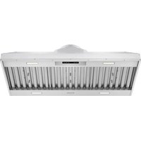
XLH48 - Basket Thor - Free user manual and instructions
Find the device manual for free XLH48 Thor in PDF.


| Product Type | Range Hood |
| Brand | Thor |
| Model | XLH48 |
| Dimensions (W × D × H) | 46 3/8 × 22 1/2 × 12 inches (117.8 × 57.2 × 30.5 cm) |
| Net Weight | 63.6 lb (28.9 kg) |
| Power Supply | 120 V ~ 60 Hz, 15/20 A |
| Duct Diameter | 10 inches (25.4 cm) round |
| Number of Fan Speeds | 6 |
| Lighting | LED 6 W × 4, two levels (bright/dim) |
| Special Features | Gesture control, heat sensor, delay-off, panel lock, filter cleaning reminder |
| Filter Type | Stainless steel baffle filters (3 for XLH48 model) |
| Recommended Installation Height (gas) | Min. 24 inches, max. 30 inches above cooking surface |
| Surface Material | Stainless steel |
| Filter Cleaning | Low-temperature dishwasher or warm soapy water, every 30 days |
| Surface Cleaning | Warm soapy water and soft cloth, avoid abrasives |
| Safety | Automatic shut-off in case of overheating, panel lock, mandatory use of metal ductwork |
| Spare Parts | Baffle filters, LED light strip, capacitor, motor, PC board (contact customer service) |
| Warranty | Manufacturer warranty, requires registration at thorkitchen.com |
| Customer Service | (877) 288-8099 or thorkitchen.com/service |
Frequently Asked Questions - XLH48 Thor
User questions about XLH48 Thor
0 question about this device. Answer the ones you know or ask your own.
Ask a new question about this device
Download the instructions for your Basket in PDF format for free! Find your manual XLH48 - Thor and take your electronic device back in hand. On this page are published all the documents necessary for the use of your device. XLH48 by Thor.
USER MANUAL XLH48 Thor
Thank you for choosing THOR KITCHEN. This product has been manufactured by Thor International, 4651 E Airport Drive, Ontario, CA 91761. This manual contains all the information you will need to install / use the product correctly and safely. Please read all the instructions prior using the product, and keep this manual in a secure place for future reference. Do not remove the attached adhesive identification label containing code, model number, manufacturer and other information from the product. This label will be used by the THOR KITCHEN authorized service representative in the event that your product needs servicing.
IMPORTANT SAFETY NOTICE....5
1.1 Read and save these instructions .... 5
1.2 Electrical requirements 7
PRODUCT FEATURES / SPECIFICATION CHART....7
2.1 Product Features 7
2.2 Specification Chart....8
2.3 Circuit Diagram....8
2.4 Hood Specifications....9
EXPLODED DIAGRAM 10
LIST OF MATERIALS 11
3.1 Parts Supplied.... 11
INSTALLATION GUIDELINES....11
4.1 Location 11
4.2 Exhaust duct 11
4.3 Position 12
OPERATING INSTRUCTIONS 13
BAFFLE FILTER INSTALLATION, REMOVAL AND MAINTENANCE 15
REPLACING LIGHT STRIP 16
SURFACE MAINTENANCE 19
5.1 Surface Maintenance.... 19
5.2 Surface Cleaning and Maintenance....19
CAUTIONS....19
6.1 Special Attention when Using the Range Hood 19
TROUBLESHOOTING 20
WARRANTY 21
1.1 Read and save these instructions
WARNING
To reduce the risk of fire or electric shock, do not use this fan with any solid-state control device.
CAUTION
For General Ventilating Use Only. Do Not Use To Exhaust Hazardous Or Explosive Materials And Vapors.
WARNING
To reduce the risk of fire, electric shock, or injury to persons, observe the following:
a. Use this unit only in the manner intended by the manufacturer. If you have questions, contact the manufacturer.
b. Before servicing or cleaning unit, switch power off at service panel and lock the service disconnecting means to prevent power from being switched on accidentally. When the service disconnecting means cannot be locked, securely fasten a prominent warning device, such as a tag, to the service panel.
WARNING
To reduce the risk of a range top grease fire:
a. Never leave surface units unattended at high settings. Boilovers cause smoking and greasy spillovers that may ignite. Heat oils slowly on low or medium settings.
b. Always turn hood ON when cooking at high heat or when flambeing food (i.e. Crepes Suzette, Cherries Jubilee, Peppercorn Beef Flambe').
c. Clean ventilating fans frequently. Grease should not be allowed to accumulate on fan or filter.
d. Use proper pan size. Always use cookware appropriate for the size of the surface element.
WARNING
To reduce the risk of injury to persons in the event of a range top grease fire, observe the following*:
a. SMOTHER FLAMES with a close-fitting lid, cookie sheet, or metal tray, then turn off the burner. BE CAREFUL TO PREVENT BURNS. If the flames do not go out immediately, EVACUATE AND CALL THE FIRE DEPARTMENT.
b. NEVER PICK UP A FLAMING PAN - You may be burned.
c. DO NOT USE WATER, including wet dishcloths or towels - a violent steam explosion will result.
d. Use an extinguisher ONLY if:
- You know you have a Class ABC extinguisher, and you already know how to operate it.
- The fire is small and contained in the area where it started.
- The fire department is being called.
- You can fight the fire with your back to an exit.
* Based on "Kitchen Firesafety Tips" published by NFPA.
IMPORTANT SAFETY NOTICE
WARNING
To reduce the risk of fire, electric shock, or injury to persons, observe the following:
a. Installation work and electrical wiring must be done by qualified person(s) in accordance with all applicable codes and standards, including fire-rated construction.
b. Sufficient air is needed for proper combustion and exhausting of gases through the flue (chimney) of fuel burning equipment to prevent back drafting. Follow the heating equipment manufacturer's guideline and safety standards such as those published by the National Fire Protection Association (NFPA), and the American Society for Heating, Refrigeration and Air Conditioning Engineers (ASHRAE), and the local code authorities.
c. When cutting or drilling into wall or ceiling, do not damage electrical wiring and other hidden utilities.
d. Ducted fans must always be vented to the outdoors.
e. NEVER place a switch where it can be reached from a tub or shower.
f. Make sure the power is off before installing, wiring or maintaining
WARNING
To reduce the risk of fire, use only metal ductwork.
CAUTION
To reduce risk of fire and to properly exhaust air outside - Do not vent exhaust air into spaces within walls, ceilings, attics, crawl spaces or garages
OPERATION
Always leave safety grilles and filters in place. Without these components, operating blowers could catch onto hair, fingers and loose clothing. The manufacturer declines all responsibility in the event of failure to observe the instructions given here for installation, maintenance and suitable use of the product. The manufacturer further declines all responsibility for injury due to negligence and the warranty of the unit automatically expires due to improper maintenance.
CALIFORNIA PROPOSITION 65 WARNING
WARNING
This appliance contains chemicals known to the State of California to cause cancer and/or reproductive harm, and birth defects or other reproductive harm. For more information go to www.P65Warnings.ca.gov.
IMPORTANT SAFETY NOTICE
1.2 Electrical requirements
Important: Observe all governing codes and ordinances.
It is the customer's responsibility:
- To contact a qualified electrical installer.
- To assure that the electrical installation is adequate and in conformance with National Electrical Code, ANSI/NFPA 70 latest edition* or CSA standards C22.1-94, Canadian Electrical Code, Part 1 and C22.2 No.0-M91 - latest edition** and all local codes and ordinances.
* National Fire Protection Association Batterymarch Park, Quincy, Massachusetts 02269
** CSA International 8501 East Pleasant Valley Road, Cleveland, Ohio 44131-5575
If codes permit and a separate ground wire is used, it is recommended that a qualified electrician determine that the ground path is adequate.
Do not ground to a gas pipe.
Check with a qualified electrician if you are not sure the range hood is properly grounded.
Do not have a fuse in the neutral or ground circuit.
This appliance requires a 120V 60Hz electrical supply and connected to an individual properly grounded branch circuit protected by a 15 or 20 ampere circuit breaker or time delay fuse. Wiring must be 2 wire with ground. Please also refer to Electrical Diagram on product.
A cable locking connector (not supplied) might also be required by local codes.
Check with local requirements, purchase and install appropriate connector if necessary.
PRODUCT FEATURES / SPECIFICATION CHART
2.1 Product Features
- 6-speed options.
- Dual level lighting: Bright, Dim and Off.
- Gesture control function: Turn On and Off, adjust the fan speed.
- Heat sensor: Automatically detect temperature and turn on and off the hood.
PRODUCT FEATURES / SPECIFICATION CHART
2.2 Specification Chart
| Models XLH36 / XLH48 / XLH60 | |
| Net Weight (lbs) 54.5 / 63.6 / 72.1 | |
| Measurement (inches) | (W)34-5/16 × (D)22-1/2 × (H)12 (W)46-3/8 × (D)22-1/2 × (H)12 (W)58-15/16 × (D)22-1/2 × (H)12 |
| Maximum Voltage 120V - 60Hz | |
| Exhaust Pipe Diameter Round 10 inches | |
| Light 6W LED × 4 | |
| Certification |  |
2.3 Circuit Diagram
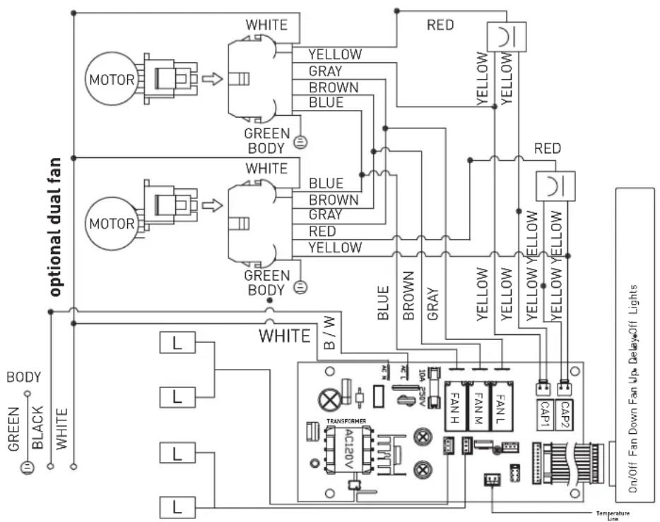
flowchart
graph TD
    subgraph "optional dual fan"
        A["MOTOR"] --> B["WHITE"]
        B --> C["GREEN BODY"]
        C --> D["WHITE"]
        D --> E["BLE"]
        E --> F["BROWN"]
        F --> G["RED"]
        G --> H["YELLOW"]
        H --> I["RED"]
        I --> J["YELLOW YELLOW"]
        J --> K["GREEN BODY"]
        L["BODY"] --> M["L"]
        N["BLACK"] --> O["L"]
        P["WHITE"] --> Q["L"]
        R["BRIDGE"] --> S["TRANSFORMER"]
        T["AC20V"] --> U["TRANSFORMER"]
        V["FANLH"] --> W["FANL"]
        X["FANL"] --> Y["FANL"]
        Z["CAP1"] --> AA["CAP2"]
        AB["ON/OFF Fan Down"] --> AC["DelayOff Lights"]
    end
    subgraph "Other dual fan"
        AD["MOTOR"] --> AE["WHITE"]
        AE --> AF["BLE"]
        AF --> AG["BROWN"]
        AG --> AH["RED"]
        AH --> AI["YELLOW"]
        AI --> AJ["RED"]
        AJ --> AK["YELLOW YELLOW"]
        AL["GREEN BODY"] --> AM["GREEN BODY"]
        AN["WHITE"] --> AO["BLE"]
        AP["BLE"] --> AQ["BROWN"]
        AR["BROWN"] --> AS["RED"]
        AT["BROWN"] --> AU["BROWN"]
        AV["BROWN"] --> AW["RED"]
        AX["BROWN"] --> AY["BROWN"]
        AZ["BROWN"] --> BA["BROWN"]
        BB["BROWN"] --> BC["BROWN"]
        BD["BROWN"] --> BE["BROWN"]
        BF["BROWN"] --> BG["BROWN"]
        BH["BROWN"] --> BI["BROWN"]
        BJ["BROWN"] --> BK["BROWN"]
        BL["BROWN"] --> BLB["BROWN"]
        BN["BROWN"] --> BNB["BROWN"]
        BO["BROWN"] --> BP["BROWN"]
        BP["BROWN"] --> BQ["BROWN"]
        BR["BROWN"] --> BS["BROWN"]
        BT["BROWN"] --> BU["BROWN"]
        BV["BROWN"] --> BW["BROWN"]
        BX["BROWN"] --> BY["BROWN"]
        BZ["BROWN"] --> BQ
        CA["GREEN BODY"] --> CB["GREEN BODY"]
    end
    style "Other dual fan"
    style "Other dual fan"
    style "Other dual fan"
    style "Other dual fan"
    style "Other dual fan"
    style "Other dual fan"
    style "Other dual fan"
    style "Other dual fan"
    style "Other dual fan"
    style "Other dual fan"
    style "Other dual fan"
    style "Other dual fan"
    style "Other dual fan"
    style "Other dual fan"
    style "Other dual fan"
    classDef color fill:#f9f,stroke:#333,stroke-width:2px;
    class A,B,C,D,E,F,G,H,I,J,K,L,M,N,O,P,Q,R,S,T,U,V,W,X,Y,Z,N,N,N,N,N,N,N,N,N,N,N,N,N,N,N,N,N,N,N,N,N,N,N,N,N,N,N,N,N,N,N,N,N,N,N,N,N,N,N,N,N,N,N,N,N,N,N,N,N,N,N,N,N,N,N,N,N,N,N,N,N,N,N,N,N,N,N,N,N,N,N,N,N,N,N,N,N,N,N,N,N,N,N,N,N,N,N,N,N,N,N,N,N,N,N,N,N,N,N,N,n,Q,R,S,T,U,V,W,X,Y,Z,N,L,M,N,N,N,N,N,N,N,N,N,N,N,N,N,N,N,N,N,N,N,N,N,N,N,N,N,N,N,N,N,N,N,N,N,N,N,N,N,N,N,N,N,N,N,N,N,N,N,N,N,N,N,N,N,N,N,N,N,N,N,N,N,N,N,N,N,N,N,N,N,N,N,N,N,N,N,N,N,N,N,N,N,N,N,N,N,N,N,N,N,N,N,N,N,N,N,N,N,N,N-N,P,Q,R,S,T,U,V,W,X,Y,Z,n,L,M,LN,L,L,L,L,L,L,L,L,L,L,L,L,L,L,L,L,L,L,L,L,L,L,L,L,L,L,L,L,L,L,L,L,L,L,L,L,L,L,L,L,L,L,L,L,L,L,L,L,L,L,L,L,L,L,L,L,L,L,L,L,L,L,L,L,L,L,L,L,L,L,L,L,L,L,L,L,L,L,L,L,L,L,L,L,L,L,L,L,L,L,L,L,L,L,L,L,L,L,L,L,l,n,p,q,r,s,t,u,v,w,v,w,x,y,z,k,l,m,k,l,n,k,l,n,k,l,n,k,l,n,k,l,n,k,l,n,k,l,n,k,l,n,k,l,n,k,l,n,k,l,n,k,l,n,k,l,n,k,l,n,k,l,n,k,l,n,k,l,n,k,l,n,k,l,n,k,l,n,k,l,n,k,l,n,k,l,n,k,l,n,k,l,n,k,l,n,k,l,n,k,l,n,k,l,n,k,l,n,k,l,n,k,l,n,k,l,n,k,l,nk,l,n,k,l,n,k,l,n,k,l,n,k,l,n,k,l,n,k,l,n,k,l,n,k,l,n,k,l,n,k,l,n,k,l,n,k,l,n,k,l,n,k,l,n,k,l,n,k,l,n,k,l,n,k,l,n,k,l,n,k,l,n,k,l,n,k,l,n,k,l,n,k,l,n,k,l,n,k,l,n,k,l,n,k,l,n,k,l,n,k,l,n,k,l,n,k,l,n,k,nn,nn,nn,nn,nn,nn,nn,nn,nn,nn,nn,nn,nn,nn,nn,nn,nn,nn,nn,nn,nn,nn,nn,nn,nn,nn,nn,nn,nn,nn,nn,nn,nn,nn,nn,nn,nn,nn,nn,nn,nn,nn,nn,nn,nn,nn,nn,nn,nn,nn,NNn,nnn,nnn,nnn,nnn,nnn,nnn,nnn,nnn,nnn,nnn,nnn,nnn,nnn,nnn,nnn,nnn,nnn,nnn,nnn,nnn,nnn,nnn,nnn,nnn,nnn,nnn,nnn,nnn,nnn,nnn,nnn,nnn,nnn,nnm,nnm,nnm,nnm,nnm,nnm,nnm,nnm,nnm,nnm,nnm,nnm,nnm,nnm,nnm,nnm,nnm,nnm,nnm,nnm,nnm,nnm,nnm,nnm,nnm,nnm,nnm,nnm,nnm,nnm,nnm,nnm,nnm,nnm
REMARKS:CONDENSER 11+11uF 250VAC 2PCS FIT AC120V 60Hz
PRODUCT FEATURES / SPECIFICATION CHART
2.4 Hood Specifications
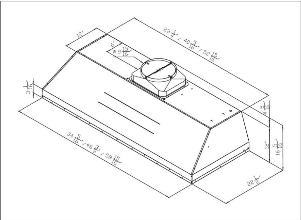
EXPLODED DIAGRAM
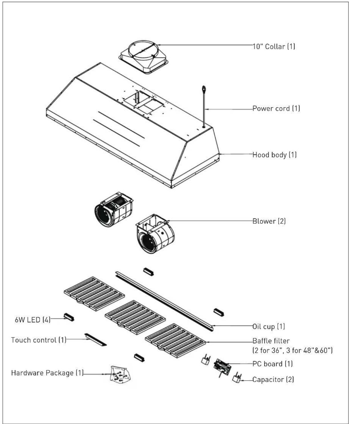
3.1 Parts Supplied
| Standard configuration Hardware packet content | ||||||
| Hood 1 #8 × 1/2" Flat Head S | 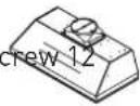 | |||||
| User Manual 1 M4 × 6mm Self |  Screw 4 Screw 4 | 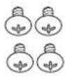 | ||||
| 10" round duct collar 1 |  | |||||
| Hardware Bracket 1 |  | |||||
INSTALLATION GUIDELINES
4.1 Location
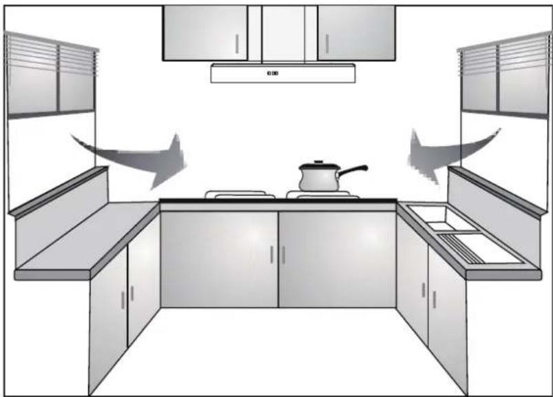
● Air turbulence from window/door may reduce the effectiveness of hood. Suggest to close window/door before using hood. (FIG. 1)
- The smoke has to rise up to 10 inches from cook top in order to reach hood's suction efficiency range.
1
natural_image
Interior view of a modern kitchen with built-in cabinets and a pan on the counter (no text or symbols)4.2 Exhaust duct
- 10" diameter exhaust duct is recommended to use in order to maximize suction efficiency.
- Before installing the hood, please apply fast drying glue to the collar and securely attach it to the top of cooker hood's vent lid. Install the cooker hood and exhaust duct to the plastic collar and seal with fast drying glue.
INSTALLATION GUIDELINES
4.3 Position
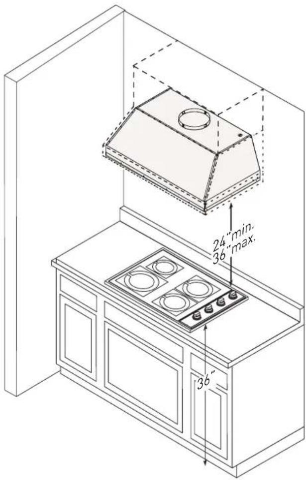
- The installation height is measured vertically from center of aluminum filter of hood to the top of the cook top.
● The min height is 24 inches and the max installation height is 36 inches for gas hob. (FIG. 2) - Avoid left-right or front-dropped inclination.
2
On / Off Fan Down Fan Up Delay Off Lights
WARNING
When the sensor encounters heavy smoke or is obscured by an object, there is a chance to activate the gesture function to automatically turn on the hood.
Gesture Function
While the fan is off
- Wave your hand in front of the control panel from left to right, the hood will turn on at speed 1.
- When turning off the fan, there is no action when swiping to the left.
- The hood has a memory function to remember the last used settings for the fan and lights.
While the fan is on
- Wave your hand from left to right in front of the control panel to increase fan speed, from right to left to decrease fan speed.
- When the fan is on speed 1, waving your hand from right to left will turn off the entire hood (fan and lights).
NOTICE
- The distance between hand and the sensor should be no more than 4 inches.
- The sensors are located at the right and left of the control panel.
Heat Sensor
This hood is equipped with a Heat Sensor.
- Automatic Fan Activation: When the hood is turned off, the fan will automatically start at speed 3, if the heat sensor detects a temperature exceeding 55^ (131°F) above the cooking surface. The fanwill turn off automatically when the temperature drops to 40^ (104°F).
- Temporary Sensor Disable: If the heat sensor detects a temperature exceeding 55^ C ( 131^ F) while the hood is off, and you adjust the fan speed or use the delay-off function, the sensor will be temporarily disabled for 20 minutes. After this period, the sensor will reactivate and resume monitoring.
NOTICE The heat sensor will be disabled when you press the fan up/down buttons or the delay off button.
1. On/Off
- Press to turn power on and off for the entire hood (fan and lights).
- Hood will remember the last speed and light level it was turned off at.
OPERATING INSTRUCTIONS
Control Panel Lock Function
- Activate the control panel lock function
While the hood is off, press and hold On/Off for 3 seconds to activate the control panel lock function, all the fan speed indicator will illuminate.
- Deactivate the control panel lock function
While the control panel lock function is activate, press and hold the On/Off for 3 seconds to deactivate the control panel lock function, all the fan speed indicator will turn off.
NOTICE When the control panel lock function is activated, all buttons on the control panel, including gesture functions, will be disabled. This feature is intended for use during surface cleaning to prevent accidental activation of the hood.
2. Speed Selection Button
Fan Down
- Press to decrease fan speed from 6, 5, 4, 3, 2, 1, off.
Fan Up
- Press to increase fan speed from 1, 2, 3, 4, 5, 6.
3. Delay Off
- While the fan is on, press and hold Delay off button for 2 seconds to enable the delay off function, all the fan speed LED indicator will keep slowly blink.
- In the setting state, press Fan Down or Fan Up button to set the delay time range from 2mins to 12 mins, default is 2 mins.
- The selected minute will correspond to the flashing of the fan speed LED indicator. For example, selecting 2 minutes = fan speed 1 slowly blink.
- The delay off timer will automatically confirm if without any operation in 5 seconds.
- When the delay off function is operating, the fan will change to speed 1 and starts the delay off countdown, use the gesture function or press the Fan Down or Fan Up button can switch the fan speed.
- After the timer expires, the fan and lights will power off.
NOTICE When the delay off function is operating, press Delay off button to disable the delay off function, press On/Off button will turn off the entire hood and delay off function.
4. Lights
- Press to change lighting level from Low, High, off.
OPERATING INSTRUCTIONS
5. Filter Clean Reminder
- After 30 hours of fan usage, all the fan speed LED indicator will begin to slowly blink indicating it is time to clean the filters.
- Keep pressing the Lights button for 3 seconds to remove this symbol if the filter have been cleaned.
NOTICE
The fan speed LED indicator will continued blinking when the fan off until pressed the Lights button for 3 seconds to remove the reminder.
BAFFLE FILTER INSTALLATION, REMOVAL AND MAINTENANCE
Installing the Baffle Filters
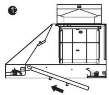
- Place filter into top groove of the liner as shown and pull towards front of liner using handles.
- Pivot back of filter upwards so it is angled in the liner.
- Push filter into channel on back of liner to lock into place.
natural_image
Technical line drawing of a mechanical assembly with an inclined plane and structural components (no text or symbols)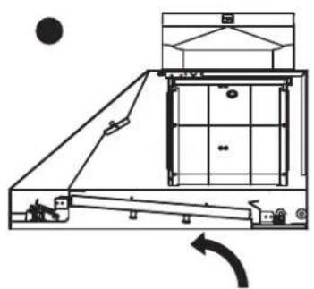
natural_image
Technical line drawing of a mechanical device with no visible text or symbols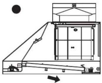
natural_image
Technical line drawing of a mechanical assembly with no visible text or symbolsBAFFLE FILTER INSTALLATION, REMOVAL AND MAINTENANCE
Removing the Baffle Filters
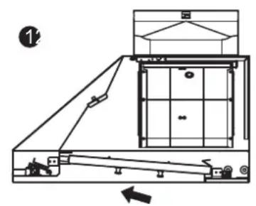
- Pulling filter toward front of liner.
- Pivoting rear of filter down.
- Pull filter out of the channel on front of liner to remove.
natural_image
Technical line drawing of a mechanical assembly with no visible text or symbols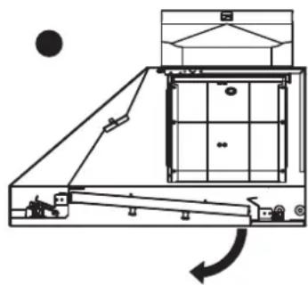
natural_image
Technical line drawing of a mechanical assembly with no visible text or symbols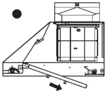
natural_image
Technical line drawing of a mechanical assembly with no visible text or symbolsCleaning the Baffle Filters
The filters are intended to trap residue and grease from cooking. Although the filters should never need replacing, they are required to be cleaned every 30 days or more often depending on cooking habits.
Filters may be placed in dishwasher at low heat or soaked in hot soapy water Dry filters and re-install before using hood.
REPLACING LIGHT STRIP
LED Light:
For LED light strip replacement or service, please contact Thor Kitchen customer service or parts department.
WARNING
Improper installation, service, or maintenance may cause injury or damage. Refer to this manual for detailed instructions. All other service should be performed by an authorized service provider.
Failure to follow these instructions can result in serious injury, fire, or electrical shock.
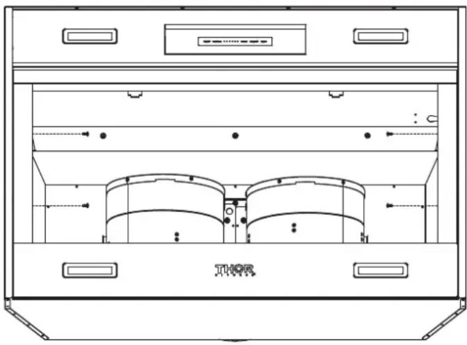
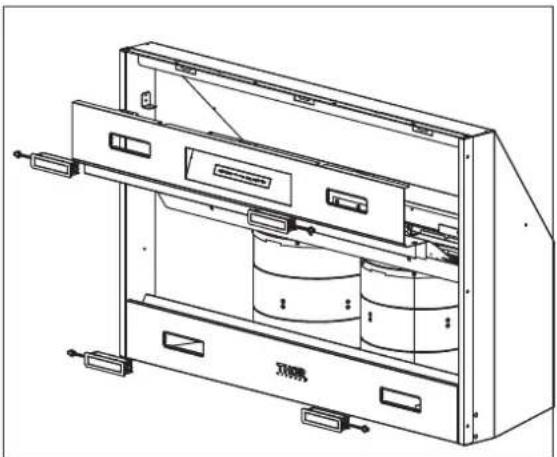
- After turning off the power, remove baffle filters.
- Remove two screws on both sides and remove the side panel. (for 36" & 60")
natural_image
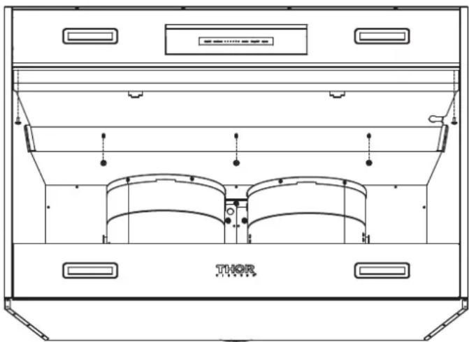
Technical line drawing of a Thermostor cabinet with ventilation ducts and control buttons (no text labels or symbols)- Remove light panel by five screws.
natural_image
Technical line drawing of a thoracic chamber with labeled components (no text or symbols beyond 'THOR' label)REPLACING LIGHT STRIP
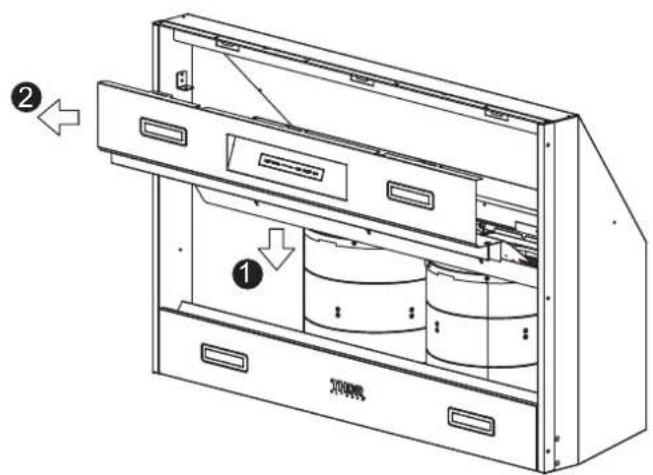
- Press the light panel and pull it forward to remove the lighting panel.
- Disconnect LED light quick connector.
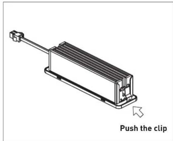
- Push the clips on each side of the LED light strips simultaneously and take off the light strip.
natural_image
Technical line drawing of a mechanical device with internal components and mounting brackets (no text or symbols)SURFACE MAINTENANCE
5.1 Surface Maintenance
- Please clean the range hood surface regularly with warm soapy water and wipe with a cotton cloth to prevent grease from accumulating.
- Please do not use harsh cleansers or coarse material to clean the surface because that will damage the surface.
- A non-invasive stainless steel polish is recommended to polish the surface after cleaning.
- Please use soft material for polishing because it will make your range hood surface shinier.
- Please do not use cleaning solutions that have bleach as an ingredient.
5.2 Surface Cleaning and Maintenance
- Always disconnect from power supply before cleaning.
- Clean both exterior and interior of the hood for long lasting. Do not use abrasive cleanser.
- Make a habit of turning on the hood first before turning on the stove to avoid high temperature in the kitchen.
CAUTIONS
6.1 Special Attention when Using the Range Hood
● The range hood must be turned on every time before cooking to ensure maximum ventilation effect.
- If there is damage to the power cord, removing and changing the power cord must be handled by the manufacturer, installer or a qualified electrician.
- When the range hood, gas stove, or other fuel appliances are being used simultaneously, there must be good ventilation in the kitchen.
- If cleaning the range hood is conducted without following the instructions in the manual, you may risk causing a fire.
- Do not light a fire directly under the range hood.
- The exhaust gas from the range hood can't be fed into the exhaust channel of the gas stove or any other appliances.
- The minimum distance required between the top of the stove and the bottom of the range hood is 24 inches. If the range installation manual states that more distance are required, it must be taken into consideration. Adjust range hood to appropriate height for complete emission of exhaust.
● To avoid danger, parts in the range hood must be disassembled with tools, and not using bare hands.
TROUBLESHOOTING
| Problem Possible cause Solution | ||
| Motor stops running 1. | No power (burned wire) or burned fuse. | 1. Replace the PC board. |
| 2. Check power meter (replace power cord). | ||
| 2. Motor temperature regulator is off and can't be recovered. | 2. Replace motor. | |
| 3. Motor copper wire is burned. 3. | Replace motor. | |
| 4. Capacitor defected. 4. Replace capacitor. | ||
| Motor speed slows down automatically | 1. Distorted capacitor or low power. | 1. Replace capacitor. |
| 2. Motor defected. 2. Replace motor. | ||
| Inverted fan blades 1. | Short circuit on the motor. 1. Replace motor. | |
| 2. Air comes out of the air outlet instead of sucks up. | 2. Air outlet or exhaust pipe is blocked and needs cleaning. | |
| Motor doesn't regulate speed | 1. Capacitor defected. 1. Replace capacitor. | |
| 2. Electrical wiring is off. 2. Fix the electrical wires. | ||
| Motor runs on and off | 1. Motor stops running when it reaches unusual high temperature, and starts again when it cools down to normal cooking temperature. This is cause by temperature running too high during cooking. | 1. Recommend changing your cooking routine slightly. |
| 2. Replace motor. | ||
| Two sections of the LED light not working | 1. LED light failed. 1. Replace LED light. | |
THOR KITCHEN®
Warranty&Service
This product has been manufactured by Thor International, 4651 E Airport Drive, California 91761
For Customer Service, please call (877) 288 - 8099
For the most up to date warranty and service policy, please refer to our website WWW.THORKITCHEN.COM/WARRANTY-REGISTRATION
For in-warranty service requests, please visit our website at WWW.THORKITCHEN.COM/SERVICE
Please Note: You must provide proof of purchase or installation date for any in-warranty service requests
TABLE DES MATIÈRES
REMARQUE IMPORTANTE CONCERNANT LA SÉCURITÉ....23
natural_image
Interior view of a modern kitchen with built-in cabinets, a potted pot, and overhead air ducts (no text or symbols)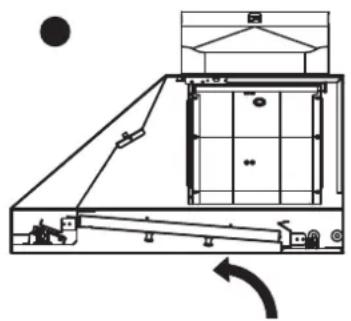
natural_image
Technical line drawing of a mechanical assembly with no visible text or symbols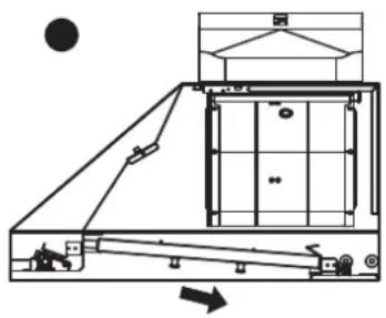
natural_image
Technical line drawing of a mechanical assembly with no visible text or symbolsINSTALLATION, RETRAIT ET ENTRETIEN DES FILTRES À CHICANES
natural_image
Technical line drawing of a thoracic chamber with ventilation ducts and control buttons (no text or symbols)natural_image
Technical line drawing of a mechanical enclosure or enclosure with labeled components (no text or symbols beyond 'THOR' label)REMPLACEMENT DE LA BANDE LUMINEUSE
natural_image
Technical line drawing of a mechanical device with internal components and mounting brackets (no text or symbols)ENTRETIEN DE LA SURFACE
5.1 Entretien de la surface
natural_image
Interior view of a modern kitchen with built-in cabinets, a potted pot, and overhead air ducts (no text or symbols)4.2 Ducto de escape
natural_image
Technical line drawing of a mechanical assembly with no visible text or symbols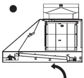
natural_image
Technical line drawing of a mechanical assembly with no visible text or symbols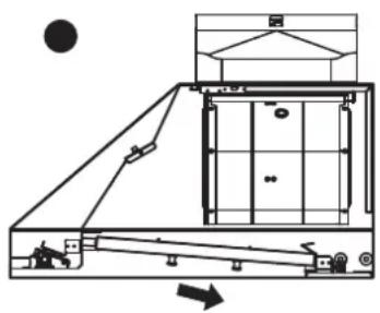
natural_image
Technical line drawing of a mechanical assembly with no visible text or symbolsnatural_image
Technical line drawing of a Thermostor appliance cabinet with ventilation ducts and control buttons (no text labels or symbols)natural_image
Technical line drawing of a mechanical or electrical enclosure with labeled components (no readable text or symbols)REEMPLAZO DE LA CINTA DE LUCES
natural_image
Technical line drawing of a mechanical device with internal components and mounting brackets (no text or symbols)MANTENIMIENTO DE LA SUPERFICIE
You chose THOR Kitchen to enhance your culinary journey and we're stoked to have you in the club. Think of it as a secret society of really savvy people, such as yourself, choosing professional power and performance at an affordable price.

Register your product by following the steps below.
WARRANTY REGISTRATION

Scan the QR code or visit thorkitchen.com/warranty
Input your product info and select register

You're done. Let's get cookin'.
WARRANTY NEED PARTS?


- IMPORTANT SAFETY NOTICE....5
- PRODUCT FEATURES / SPECIFICATION CHART....7
- EXPLODED DIAGRAM 10
- LIST OF MATERIALS 11
- INSTALLATION GUIDELINES....11
- OPERATING INSTRUCTIONS 13
- BAFFLE FILTER INSTALLATION, REMOVAL AND MAINTENANCE 15
- REPLACING LIGHT STRIP 16
- SURFACE MAINTENANCE 19
- CAUTIONS....19
- TROUBLESHOOTING 20
- WARRANTY 21
- Read and save these instructions
- WARNING
- CAUTION
- IMPORTANT SAFETY NOTICE
- OPERATION
- Electrical requirements
- PRODUCT FEATURES / SPECIFICATION CHART
- Product Features
- Circuit Diagram
- Hood Specifications
- EXPLODED DIAGRAM
- Parts Supplied
- INSTALLATION GUIDELINES
- Location
- Exhaust duct
- Position
- Gesture Function
- While the fan is off
- While the fan is on
- NOTICE
- Heat Sensor
- On/Off
- OPERATING INSTRUCTIONS
- Control Panel Lock Function
- Speed Selection Button
- Fan Down
- Fan Up
- Delay Off
- Lights
- Filter Clean Reminder
- BAFFLE FILTER INSTALLATION, REMOVAL AND MAINTENANCE
- Installing the Baffle Filters
- Removing the Baffle Filters
- Cleaning the Baffle Filters
- REPLACING LIGHT STRIP
- LED Light:
- SURFACE MAINTENANCE
- Surface Maintenance
- Surface Cleaning and Maintenance
- CAUTIONS
- Special Attention when Using the Range Hood
- TROUBLESHOOTING
- THOR KITCHEN®
- Warranty&Service
- TABLE DES MATIÈRES
- REMARQUE IMPORTANTE CONCERNANT LA SÉCURITÉ....23
- INSTALLATION, RETRAIT ET ENTRETIEN DES FILTRES À CHICANES
- REMPLACEMENT DE LA BANDE LUMINEUSE
- ENTRETIEN DE LA SURFACE
- Entretien de la surface
- Ducto de escape
- REEMPLAZO DE LA CINTA DE LUCES
- MANTENIMIENTO DE LA SUPERFICIE
- WARRANTY REGISTRATION
Brand : Thor
Model : XLH48
Category : Basket