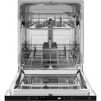
DW60S2IEPDV - Dishwasher BERTAZZONI - Free user manual and instructions
Find the device manual for free DW60S2IEPDV BERTAZZONI in PDF.


| Product type | Built-in dishwasher |
| Brand | Bertazzoni |
| Model | DW60S2IEPDV |
| Dimensions (W x H x D) | 600 mm x 820 mm x 580 mm |
| Power supply | 220-240 V, 50 Hz, 10 A |
| Total power | 1760-2100 W |
| Heating power | 1800 W |
| Water pressure admissible | 0.04-1 MPa (0.4-10 bar) |
| Capacity | 12 place settings |
| Number of programs | 6 (Intensive, Universal, Eco, Glass, Rapid 90 min, Rapid 30 min) |
| Options | Half load, Delayed start (1-24 h) |
| Water consumption (Eco) | 11.0 L/cycle |
| Energy consumption (Eco) | 0.92 kWh/cycle |
| Eco cycle duration | 3 h 50 min |
| Noise level | Not specified |
| Installation type | Built-in (custom panel possible) |
| Water softener | Yes, adjustable (H1 to H6) |
| Detergent dispenser | Yes, with tablet compartment |
| Rinse aid dispenser | Yes, adjustable dosage (D1 to D5) |
| Salt dispenser | Yes, for water softener |
| Tub material | Stainless steel |
| Safety | Automatic stop on door opening, steam protection, grounding |
| Maintenance | Removable filters, detachable spray arms, monthly cleaning recommended |
| Repairability | Spare parts available via Bertazzoni after-sales service |
Frequently Asked Questions - DW60S2IEPDV BERTAZZONI
User questions about DW60S2IEPDV BERTAZZONI
0 question about this device. Answer the ones you know or ask your own.
Ask a new question about this device
Download the instructions for your Dishwasher in PDF format for free! Find your manual DW60S2IEPDV - BERTAZZONI and take your electronic device back in hand. On this page are published all the documents necessary for the use of your device. DW60S2IEPDV by BERTAZZONI.
USER MANUAL DW60S2IEPDV BERTAZZONI
| EN | INSTALLATION MANUALUSER AND MAINTENANCE MANUALDW60S2IEPDV | 3 |
| IT | MANUALE D'INSTALLAZIONEMANUALE D'USO E MANUTENZIONEDW60S2IEPDV | 55 |
| FR | MANUEL D'INSTALLATIONMANUEL D'UTILISATION ET D'ENTRETIENDW60S2IEPDV | 109 |
| SV | INSTALLATIONSHANDBOKBRUKS- OCH UNDERHÅLLSHANDBOKDW60S2IEPDV | 163 |
| NL | INSTALLATIEHANDLEIDINGGEBRUIKS- EN ONDERHOUDSHANDLEIDINGDW60S2IEPDV | 215 |
| DA | INSTALLATIONSVEJLEDNINGBRUGS- OG VEDLIGEHOLDELSESVEJLEDNINGDW60S2IEPDV | 269 |
FROM THE DESK OF OUR PRESIDENT
Dear new owner of a Bertazzoni appliance,
I want to thank you for choosing one of our beautiful products for your home.
My family started manufacturing kitchen appliances in Italy in 1882, building a reputation for quality of engineering and passion for good food.
Today, our products stand out because of their unique blend of authentic Italian design and superior appliance technology. It is our mission to make products that function perfectly and bring joy to their owners.
By making beautiful products we respond to our customers' flair for good design. By making them versatile and easy-to-use, cooking with Bertazzoni becomes a real pleasure.
This manual will help you learn to use and care for your Bertazzoni appliance in the safest and most effective way, so that it can give you the highest satisfaction for years to come.
Enjoy!
Paolo Bertazzoni
President
USER MANUAL VALIDITY
The following manual is valid only for DW60S2IEPDV product code.
GENERAL INFORMATION 7
SAFETY INFORMATION 8
RECYCLING 9
CE DECLARATION OF CONFORMITY 9
DISPOSAL OF YOUR OLD MACHINE 9
INSTALLATION MANUAL 10
SPECIFICATIONS 10
GENERAL APPEARANCE 10
TECHNICAL SPECIFICATIONS 10
INSTALLATION 11
CUTOUT DIMENSIONS 11
CUSTOM DOOR PANEL (FOR PANEL-READY MODELS) 11
POSITIONING THE DISHWASHER 12
ELECTRICAL REQUIREMENTS 13
PLUMBING REQUIREMENTS 14
INSTALLATION 16
USER AND MAINTENANCE MANUAL 24
USE 24
GETTING STARTED 24
PLATE ARRANGEMENT 26
RACKS 31
CONTROL PANEL 37
OPERATION 38
DETERGENT & RINSE-AID DISPENSER 41
SALT DISPENSER (FOR MODELS WITH WATER SOFTENER) 44
CLEANING AND CARE 46
SPRAY ARMS 47
FILTER 48
DRAIN PUMP 48
TROUBLESHOOTING 49
AUTOMATIC FAULT WARNINGS 51
PRACTICAL INFORMATION 52
WARRANTY AND ASSISTANCE 53
WARRANTY AND SERVICE 53
These instructions are suitable for different types of appliances, so they may contain descriptions of functions which your appliance may not include or support.
The images and illustrations in this document refer to various models and may differ slightly from the product purchased.
The manufacturer does not accept any liability for personal injury or damage to property arising from incorrect installation or misuse of the appliance.
The manufacturer reserves the right to modify the various models as required to comply with the technical regulations in force.
In the event of complaints, please contact customer service. Read the instructions provided in this manual thoroughly before installing and/or using the appliance. This will help you get to know your new appliance. Keep this document at hand so that you can consult it at any moment, and pass it on to any subsequent owners.
Read the safety messages provided in the introduction to this manual and give due consideration to the safety notes, such as: "Attention", "Warning" and "Danger" which appear in the text.

DANGER
This symbol indicates a situation that is a danger to you and others. Read it carefully and make sure that you have perfectly understood the causes of potential dangerous or fatal accidents.

WARNING
This symbol indicates safety information. Read it carefully and make sure that you have perfectly understood the causes of potentially dangerous accidents.

CAUTION
This symbol indicates a procedure which could put the appliance's structure or components at risk. Take particular care over these procedures.

NOTE
This symbol highlights methods or procedures for correct use of the appliance.
The Model, Sales Code and Serial Number are printed on the nameplate. Refer to the Specifications section of this manual for nameplate location.

NOTE
You are advised to make a note of the appliance's data and serial numbers so they are immediately available if required.

NOTE
State the information provided on the nameplate to improve the efficiency of the after-sales and parts services. For warranty purposes, you will also need the date of installation and name of your authorized Bertazzoni dealer.
SAFETY INFORMATION

WARNING
When using your dishwasher, follow basic precautions. Read all instructions before using the dishwasher. Save these instructions and pass them on to any future user.
- Use the dishwasher only for its intended purpose.
• This appliance is intended for residential use only. - Use only detergents recommended for use in a dishwasher and keep them out of the reach of children.
-
When loading items to be washed:
-
place sharp items so they are not likely to damage the door seal, and
-
load sharp knives with the handles up to reduce the risk of injury.
-
Do not wash plastic items unless they are marked "dishwasher safe" or equivalent. For unmarked plastic items, check the manufacturer's recommendations.
- Do not touch the heating element during or immediately after use.
- Do not tamper with the controls.
- Do not operate your dishwasher unless all enclosure panels are properly in place.
- Do not remove the dishes from the appliance until the wash cycle is complete.
- To avoid risk of injury, always use caution when opening the door during or following a wash cycle as hot water steam may escape.
- Check that the detergent dispenser is empty after the completion of each wash cycle.
- Some dishwasher detergents are strongly alkaline. They can be extremely dangerous if swallowed. Avoid contact with the skin and eyes and keep children away from the dishwasher when the door is open.
- Do not misuse, sit on, or stand on the door or dish rack of the dishwasher. The appliance could tip forward.
- The cup racks are designed to hold cups, glasses, and kitchen utensils. Do not lean on or use the cup racks to support your body weight.
- To avoid a tripping hazard, do not leave the dishwasher door open.
- Do not allow children to play in or on a dishwasher (EN60335-1).
- When children become old enough to operate the appliance, it is your responsibility to ensure that they are properly instructed about the safety practices contained in this manual.
- This appliance is not intended for use by persons (including children) with reduced physical, sensory or mental capabilities, or lack of experience and knowledge, unless they have been given supervision or instruction concerning use of the appliance by a person responsible for their safety (IEC60335-1).
This appliance must be grounded. In the event of a malfunction or breakdown, grounding will reduce the risk of electric shock by providing a path of least resistance for electric current. This appliance is equipped with a cord having an equipment grounding conductor and a grounding plug. The plug must be plugged into an appropriate outlet that is installed and grounded in accordance with all local codes and ordinances.

WARNING
Improper connection of the equipment-grounding conductor can result in a risk of electric shock. Check with a qualified electrician or service representative if you are in doubt whether the appliance is properly grounded. Do not modify the plug provided with the appliance if it does not fit the outlet. Have a proper outlet installed by a qualified electrician.

WARNING
Before any maintenance operation, turn off the appliance and disconnect the mains plug from the socket.
Do not use high pressure water sprays and/or steam to clean the appliance.
^a Ensure there are no visible water leaks during and after first use of the appliance.
To avoid floor damage and possible mold growth, do not allow wet areas to remain around or under the dishwasher.
To avoid dishwasher damage, do not allow water to remain in your dishwasher system through extended freezing periods.
Do not store or use flammable liquids or vapors inside, near, or on the appliance.
Under certain conditions, hydrogen gas may be produced in a hot water system that has not been used for two or more weeks. HYDROGEN GAS IS EXPLOSIVE. If the hot water system has not been used for two or more weeks, before using the dishwasher, turn on all hot water faucets and let the water flow from each for several minutes. This releases any accumulated hydrogen gas. As the gas is flammable, do not smoke or use an open flame during this time.
Please check the water supply line periodically. It is susceptible to breakage. It becomes less flexible as time goes by. Replace it immediately when it is torn, cut, swollen, or there is water leakage.
- Please unplug the appliance before cleaning and maintenance.
- When loading your dishwasher, locate sharp items so that they are not likely to damage the door seal.

WARNING
Knives and other utensils with sharp points must be loaded in the basket with their points facing down or placed in a horizontal position.
RECYCLING
Packaging materials protect your machine from damage that may occur during transportation. The packaging materials are environmentally friendly as they are recyclable. The use of recycled material reduces raw material consumption and therefore decreases waste production.
Some machine components and packaging consist of recyclable materials:
- Plastics are marked with the international abbreviations: (>PE<, >PP<, etc.)
- The cardboard parts consist of recycled paper. They can be put into wastepaper containers for recycling.
- Material unsuitable for domestic waste must be disposed of at recycling centres.
- Contact a relevant recycling centre to obtain information about disposal of different materials.
CE DECLARATION OF CONFORMITY
We declare that our products meet the applicable European Directives, Decisions and Regulations and the requirements listed in the standards referenced.
DISPOSAL OF YOUR OLD MACHINE

The symbol on the product or on its packaging indicates that this product may not be treated as household waste. Instead, it shall be taken to the applicable collection point for the recycling of electrical and electronic equipment. By ensuring this product is disposed of correctly, you will help prevent potential negative consequences for the environment and human health, which could otherwise be caused by inappropriate waste handling of this product. For more detailed information about recycling this product, please contact your local city office, your household waste disposal service or the shop where the product was purchased.
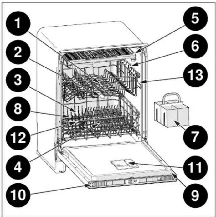
Fig. 1
GENERAL APPEARANCE
1) Upper basket
2) Upper spray arm
3) Lower basket
4) Lower spray arm
5) Third rack (depending on model)
6) Top nozzle (depending on model)
7) Silverware basket (depending on model)
8) Filters
9) Rating plate
10) Control panel
11) Detergent and rinse-aid dispenser
12) Salt dispenser
13) Upper basket track latch
TECHNICAL SPECIFICATIONS
| Permissible water pressure | 0,04 - 1 MPa (0,4 - 10 bars) |
| Electrical connection | 220-240 V (volts), 10 A (amps), 50 Hz (hertz) |
| Total power | 1760 - 2100 (W) |
| Heater power | 1800 (W) |

NOTE
Because we continually strive to improve our products, we may change our specifications and design without prior notice. This device corresponds to the following directives:
EU ecodesign legislation.
CUTOUT DIMENSIONS
Cabinet depth shown includes kitchen cabinet front panel. For a flush installation, a minimum inset depth of 580 mm (22 13/16") is required with a custom door panel thickness of 20 mm (3/4").
TOP VIEW

Fig. 2
• A 580 mm (22 13/16")
FRONT VIEW
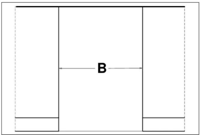
Fig. 3
• B 600 mm (23 5/8")
SIDE VIEW
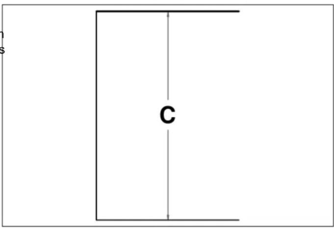
Fig. 4
• C 820 mm (32 1/4")
CUSTOM DOOR PANEL (FOR PANEL-READY MODELS)
The thickness of the custom panel may vary. A minimum 13 mm (1/2") thick panel is required, but the thickness can be increased provided the panel does not exceed 7 kg (15 lb). Minimum panel weight is 5 kg (11 lb). The custom door panel template provided accommodates panels with the dimensions specified below.
FRONT VIEW
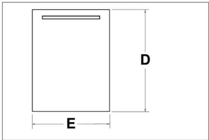
Fig. 5
• D 665 mm - 720 mm (26 3/16" - 28 3/8")
E 595 mm - 597 mm (23 7/16" - 23 1/2")
POSITIONING THE DISHWASHER
When positioning the machine, place it in an area where dishes can be easily loaded and unloaded. Do not put the machine in an area where the ambient temperature falls below 0^ C.
Read all warnings located on the packaging before removing the packaging and positioning the machine. Place the machine close to a water tap and drain. Take into consideration that the connections will not be altered once the machine is in position.
The dishwasher is equipped with water supply and drain hoses that can be positioned either to the right or the left sides to facilitate proper installation.
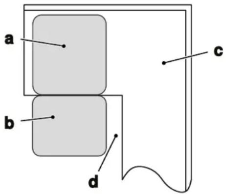
Fig. 6
Leave an adequate distance around the machine to allow a. Dishwasher. ease of movement when cleaning.

CAUTION
Do not hold the machine by its door or panel.
b. Door of dishwasher.
c. Cabinet.
d. Minimum space of 50 mm.

CAUTION
Ensure the water inlet and outlet hoses are not squeezed or trapped and that the machine does not stand on the electrical cable while positioning.

NOTE
Depending on where your electrical outlet is, you may need to cut a hole in the opposite cabinet side.
Adjust the feet so the machine is level and balanced. The machine should be placed on flat ground otherwise it will be unstable and the door of the machine will not close properly.

CAUTION
Please install the decorative panel as indicated on the assembly sheet. Otherwise, the door may not open properly and steam leakage problem may occur.
If the dishwasher is placed at the corner of the cabinet, there should be some space when the door is opened.
If the dishwasher is placed next to a corner cabinet, additional space should be left so that the door can be opened.
ELECTRICAL REQUIREMENTS
Please check the electrical standards and local codes before installing the appliance.
Connect to a properly rated, protected, and sized power supply circuit to avoid electrical overload. The dishwasher is designed for an electrical supply of 220-240 V (volt), 50 Hz (hertz), connected to a separate, properly-grounded electrical circuit servicing only this appliance, with a fuse or breakers rated for 10 amperes. Connect the product to a grounded outlet protected by a fuse. The earthed plug of the machine must be connected to an earthed outlet supplied by suitable voltage and current.
If the mains voltage supply to your machine is 110 V, connect a transformer of 110/220 V and 3000 W between the electrical connection.
Never connect the ground wire to gas lines, or hot water pipes, plumbing lines.
Do not use any extension cord or portable outlet device to connect the dishwasher to a power supply.
These requirements must be met to prevent injury and damage to the machine. Consult a qualified electrician if doubt.
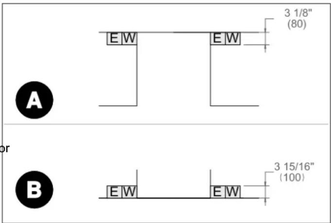
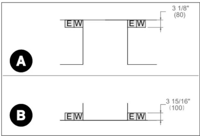
A properly-grounded, horizontally-mounted electrical receptacle should be installed according to this drawing.
in Connections placement must be located on either side of the cutout.

NOTE
The plug on this appliance may incorporate 13 A fuse depending on the target country (e.g. UK, Saudi Arabia)
PLUMBING REQUIREMENTS
Installation must comply with all applicable plumbing codes.
Place the water supply and drain in an adjacent cabinet.

NOTE
The dishwasher must be connected to a cold water inlet hose.

WARNING
A hose that attaches to a tap can burst if installed on the same water line as the dishwasher. If your sink has one, it is recommended to disconnect the hose and plug the hole.
We recommend fitting a filter to your water inlet supply in order to prevent damage to your machine due to contamination (sand, rust, etc.) from indoor plumbing. This will also help prevent yellowing and deposit formation after washing.
The edges of the opening must be smooth and round.
The water supply may be connected to the dishwasher with either:
• A metal braided hose
- Copper tubing
Use the new water inlet hose supplied with your machine, do not use an old machine's hose.
Run water through the new hose before connecting. This precaution is needed to avoid the risk of the water inlet to be blocked and damage the appliance.
Connect the cold water supply hose to a threaded 3/4" connector and make sure that it is fastened tightly in place.
The pressure supplied by the tap should be a minimum of A. max 100 cm
0.04 MPa and a maximum of 1 MPa. If the pressure
exceeds 1 MPa, a pressure relief valve must be fitted between the connection. B. min 50 cm C. min 4 cm
After the connections are made, turn the tap on fully and check for water leaks.
A safety supply hose is available with some models. The system ensures its intervention by blocking the flow of water in the event of a break in the supply hose and wh
the air space between the supply hose itself and the outer
corrugated hose is full of water.
2) Tighten the screws of the safety supply hose to the faucet with thread 3/4".
^S3 Turn the water fully on before starting the dishwasher.
To disconnect a safety supply hose:
1) Turn off the water.
2) Unscrew the safety supply hose from the faucet.
Connect the water drain hose directly to water drain pipe or to the sink outlet spigot. This connection should be minimum 50 cm and maximum 100 cm from floor that dishwasher is placed.
The free end of the hose must not be immersed in water to avoid the back flow of it.

WARNING
If the connection to the drain pipe is positioned higher than 1000 mm, excess water may remain in the drain hose. It will be necessary to drain excess water from the hose into a bowl or suitable container that is held outside and lower than the sink.
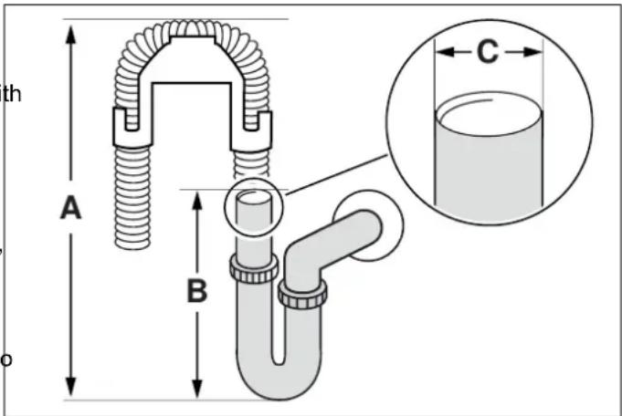
Fig. 8
A. max 100 cm
B. min 50 cm
C. min 4 cm
Purge the water supply prior to final connection to the unit.
This will remove any debris that may be present in the tubing when installing the new water supply. Connect the braided tubing from the unit to the household water supply with the fitting provided.
Check all water supply fittings for leaks.
To connect a safety supply hose:
1) Pull the safety supply hoses out from storage compartment located at rear of dishwasher.

NOTE
Items will not wash properly if an extension drain hose longer than 4 m is used.
These requirements must be met to prevent injury and damage to the machine. Consult a qualified plumber if in doubt.
To connect the water mains to the water inlet valve thread, use a 3/4" threaded connector (not supplied).
INSTALLATION
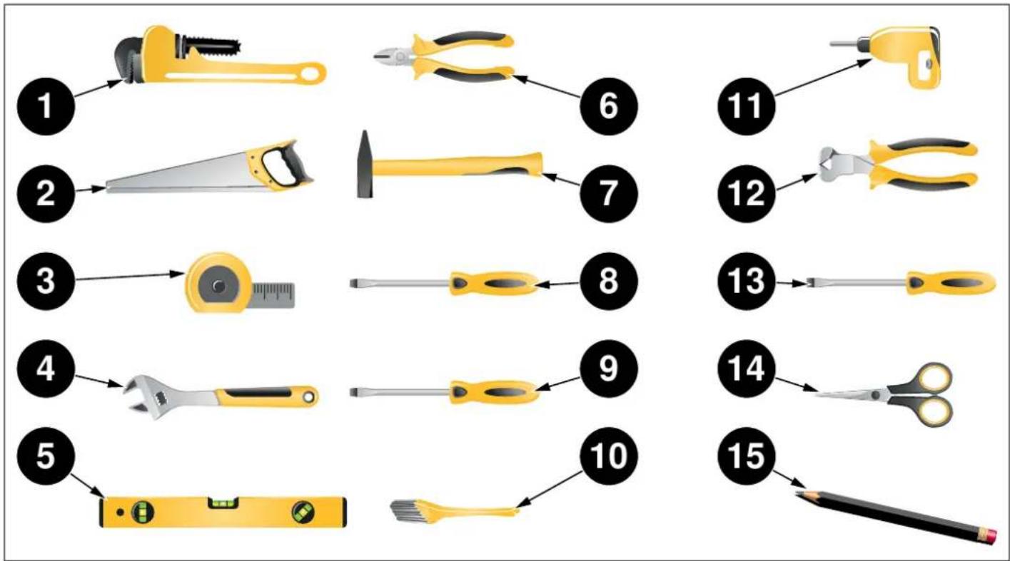
TOOLS THAT MAY BE REQUIRED
flowchart
graph TD
    A["1: Top Tool"] --> B["2: Top Gear"]
    B --> C["3: Top Clip"]
    C --> D["4: Top Towel"]
    D --> E["5: Top Scale"]

    F["6: Slipped Pin"] --> G["7: Top Handle"]
    G --> H["8: Screwdriver"]
    H --> I["9: Top Towel"]
    I --> J["10: Top Scale"]

    K["11: Top Screw"] --> L["12: Top Clip"]
    L --> M["13: Screwdriver"]
    M --> N["14: Top Scissors"]
    N --> O["15: Top Scale"]
Fig. 10
1 Pipe Wrench
2 Hole Saw
3 Tape Measure
4 Adjustable Wrench
5 Level
6 Wire Cutter
7 Hammer
8 Torx Screwdriver (T20)
9 Slot Screwdriver
10 Brush
11 Drill
12 Wire Stripper
13 Phillips Screwdriver
14 Scissors
15 Pencil
MATERIALS THAT MAY BE REQUIRED
(Additional materials may be required to comply with local In addition to these instructions, the dishwasher shall be installed in accordance with all local codes.
Hot Water Supply Line - Minimum 3/4" O.D. copper tubing or metal braided dishwasher supply line.
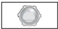
UL listed conduit connector or strain relief.
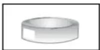
Teflon tape or other pipe thread compound to seal plumbing connections.

Shut-off valve and fittings appropriate for hot water supply line (copper tubing/compression fitting, or braided hose).
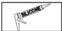
Silicone
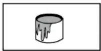
Glue
MATERIALS SUPPLIED
The parts required for positioning the dishwasher are in plastic bags. Check that all of the following parts are contained in plastic bags.
IMPORTANT SAFETY INSTRUCTIONS
In addition to these instructions, the dishwasher shall be installed in accordance with all local codes.
When installing the dishwasher, follow basic precautions, including the following:
- Installation and repair should be performed by a qualified installer. Work by unqualified persons could be dangerous and may void the warranty.

NOTE
The dishwasher should be installed by an insured licensed plumber, contractor, or trained installer. Installation performed by persons other than these could result in improper installation and damage to property.
- Do not operate the appliance if damaged, malfunctioning, partially disassembled or if it has missing or broken parts.
- Before installation or service, disconnect the power supply to the work area by unplugging the unit, “tripping” the circuit breaker or removing the fuse.
- Only connect the dishwasher to the power supply when all installation and plumbing work is complete.
- Never connect the ground wire to gas lines, or hot water pipes, plumbing lines.
- If the dishwasher is installed in a location that is subjected to freezing temperatures (e.g., vacation home, cabin, etc.), you must drain all water from the dishwasher's interior. Water system breakdowns that occur due to freezing water are not covered under warranty.
- The dishwasher must be secured to adjacent cabinetry using the brackets provided. Failure to do so may cause damage to property or bodily injury.
- The dishwasher is intended for residential use only and should not be used in commercial establishments.

NOTE
Do not use any extension cord or portable outlet device to connect the dishwasher to a power supply.

WARNING
Danger of suffocation! Ensure that any plastic wrappings, bags, small pieces, etc., are disposed of safely and kept out of the reach of children.
STEAM PROTECTION FOIL
Steam will be released when the dishwasher door is opened during operation of the dishwasher and after completion of the working cycle. In order to prevent the resulting steam from collecting and damaging the underside of the countertop, use a steam protection foil included in the plastic bag.
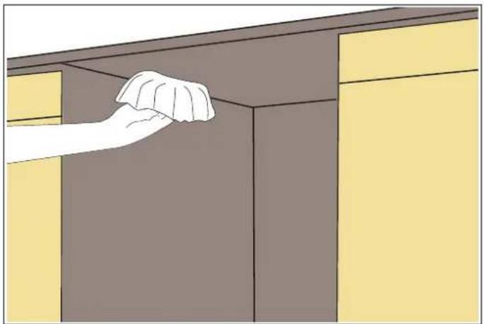
Clean the surface with a damp cloth before applying steam protection to the underside of the countertop.
natural_image
Illustration of a hand cleaning a cabinet interior (no text or symbols)Fig. 11
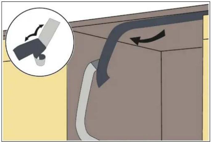
Apply the condensation strip under the countertop of the cabinet. Ensure that the condensation strip is flush with the edge of the countertop.
natural_image
Diagram showing a device interacting with a curved panel, with an inset magnified view of the device's motion (no text or symbols present)Fig. 12

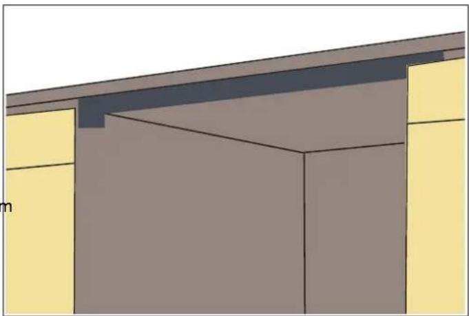
CAUTION
Steam protection foil must be applied where the steam escapes when the door is first opened. Failure to install the steam protection foil during installation can lead to damage to the cabinets and countertop.
natural_image
Architectural diagram of a modern building corner with yellow walls and gray walls (no text or symbols)Fig. 13
PLACEMENT OF DISHWASHER INTO THE OPENING
Now place the dishwasher into the opening and get ready to connect all hoses and electrical connections.
1) Connect the inlet hose to the cold water supply.
2) Connect the drain hose.
3) Connect the power cord.
4) Place the dishwasher into the cabinet.

CAUTION
Make sure that all hoses are pulled through the side opening of the cabinet, that no hoses are kinked and that all slack is taken out as shown in the figure.
ADJUSTING THE HEIGHT
1) Keep the front feet at the minimum height before and while positioning the dishwasher into the cabinet cutout.
2) Adjust the front foot level with a slot screwdriver to stabilize the dishwasher and raise it to the enclosure height.
3) Adjust the rear foot level with a Phillips screwdriver to balance and raise the dishwasher to the enclosure height.
The rear foot is located in the centre front at the base of the appliance.
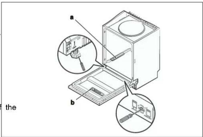
Fig. 15

NOTE
Make sure the dishwasher is plumb and note that the dishwasher can be placed with a small clearance under the countertop.
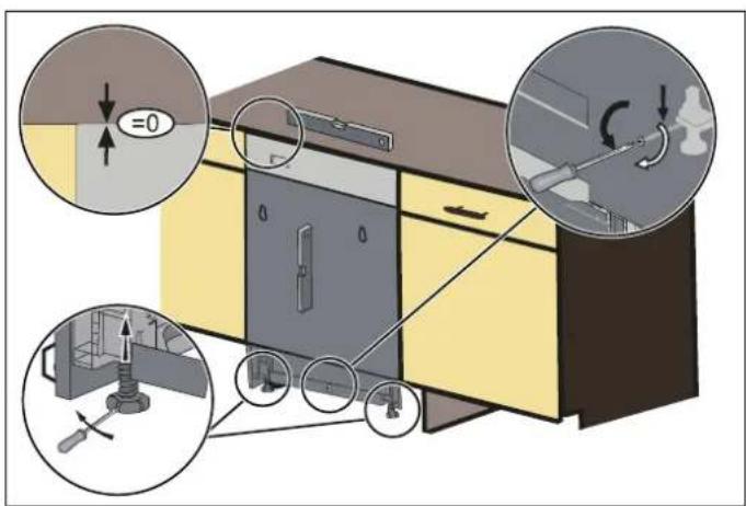
a. Check level front to back.
b. Check level side to side.

CAUTION
When levelling the dishwasher, take care not to tip it over.

NOTE
The maximum adjustment height of the feet is 50 mm.
Fig. 14
The dishwasher must be level to ensure proper dish rack operation and washing performance.
Place a spirit level on door and basket rail inside the tub, as illustrated, to check that the dishwasher is level.
Level the dishwasher by adjusting the three levelling points individually.
INSTALLING THE OUTER DOOR PANEL (DEPENDING ON MODEL)
Before starting the installation of the custom door panel, make sure that the measurements are within the ranges specified in the CUSTOM DOOR PANEL (FOR PANEL-READY MODELS) section of this manual.
1) The installation plan is in the plastic bag secured to the inside of the dishwasher door. Position the installation plan on the custom door panel aligning it with the top and drill holes at the points indicated on the installation plan.
2) Fasten the hook on the custom door panel and insert it into the slot on the outer door of the dishwasher (Fig. 16).
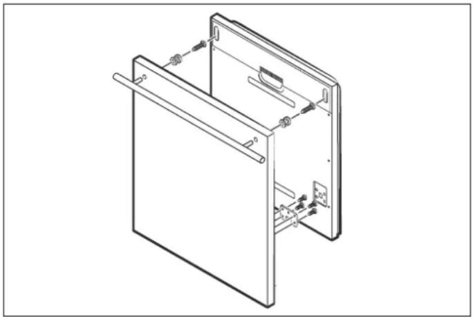
natural_image
Technical line drawing of a door frame with internal components and mounting brackets (no text or symbols)Fig. 16
3) After positioning the panel in place, fix the custom door to the outer door of the dishwasher with the screws and bolts provided (Fig. 17).
3.1) Take away the four short screws (a).
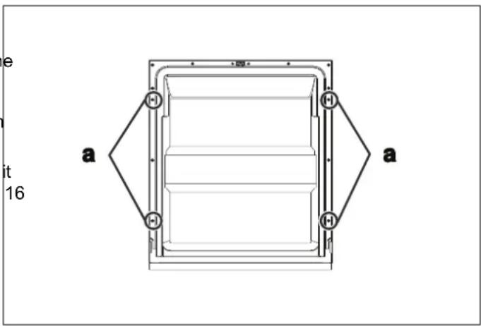
Fig. 17
3.2) Pin up the four long screws (b).
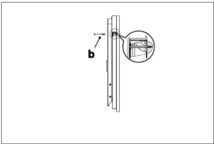
Fig. 18

NOTE
Before mounting the wooden door on the dishwasher, mount the handle on the wooden door as in Fig. 19.
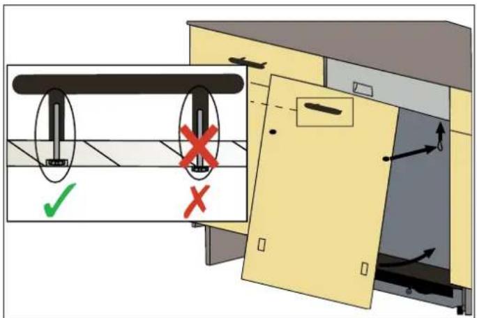
Fig. 19

Fig. 21
The door springs are set at the factory to the proper tens of FIXING THE DISHWASHER INTO THE CABINET
for the outer door of the dishwasher.
The dishwasher must be secured in place into the cabinet.
The door spring tension must be adjusted according to the weight of the custom door panel installed.
Fix the sides with the screws.
1) Turn the adjusting screw with a Philips screwdriver in a clockwise motion to tighten the left and right door springs.
2) Turn the adjusting screw with a Philips screwdriver in a clockwise motion to loosen the left and right door springs.
The door spring tension is correct when the door remains horizontal in the fully open position, but lifts up to a close with the slight lift of a finger.
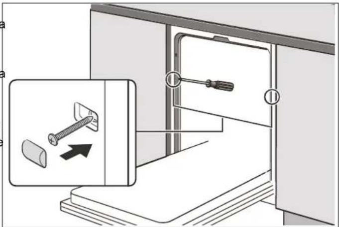
Fig. 22
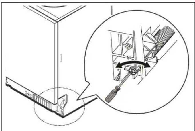
natural_image
Technical diagram showing a mechanical assembly with an inset close-up of a screwdriver inserted into a component (no text or symbols present)Fig. 20
Check whether the bottom of the door hits the toe kick of the kitchen cabinet.
- If the door hits the toe kick, cut the required section out of the toe kick.
- Apply silicone or sealant to the cut edge of the kitchen cabinet toe kick or paint it so that it does not absorb moisture.
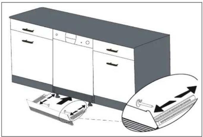
ATTACHING THE KICKPLATE
The following options are available. Follow the supplied instructions.
- Option 1: Attach the furniture kickplate.
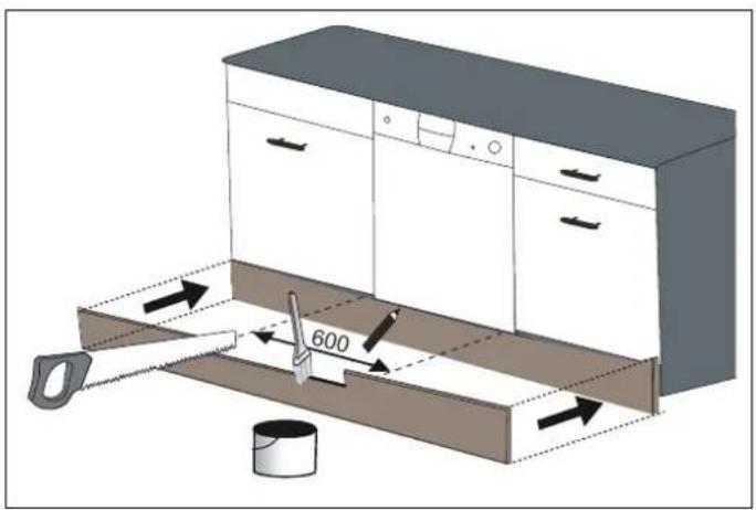
Fig. 23
- Option 2: Attach the adjustable plinth group. Follow the instructions supplied with the adjustable plinth group.
natural_image
Illustration of a kitchen appliance with a magnified view showing internal components (no text or symbols)Fig. 24
INSTALLER CHECKLIST
Your installer must have completed and checked the following:
The dishwasher is square and level.
☐ The dishwasher is fastened securely to the cabinetry.
☐ The dishwasher door opens and closes freely. The dishwasher door must close without hitting any cabinetry or countertop.
☐ The inlet water supply is turned on and checked for leaks.
☐ The drain hose has been connected and checked for leaks. There must be no kinks or obstructions in the drain hose.
☐ The drain hose must be installed with a 30" (762 mm) high drain loop for drain hook-ups without any air removed.
If you connect the water drain hose to a trap spigot under the sink, remove the plastic membrane. If you do not remove the entire membrane, leftover food could cause a blockage in the drain hose spigot. Ensure a hose clamp is used to secure the hose to the spigot.
The spray arms are free and rotate freely.
The rinse cycle has been run.
☐ The water level will be below the filter screen after the end of the wash program. It is normal to find some water in the drain filter area.
FINAL INSTRUCTIONS
1) Press the On/Off button to turn the dishwasher on.
2) Power indicator light comes on.
3) Use the Program Select button to choose a washing program.
4) Start the program with the Start/Pause button.
5) Run the dishwasher through one complete cycle. When the wash cycle is completed, use the On/Off button to turn the dishwasher off.

NOTE
If the dishwasher does not operate properly, see the Self Help Tips.
SELF-HELP TIPS
The screen does not come on:
- Check to make sure the breaker to the dishwasher is in the ON position.
- Check to make sure that the supply cord is plugged.
No water is coming into the dishwasher:
- Check to make sure the water shutoff is in the ON position.
Water does not drain:
- Make sure the drain hose is not kinked or sticking out of the air gap next to the sink.
- Remove the drain hose from the garbage disposal making sure the plug is removed.

NOTE
If your dishwasher is not operating properly after following these steps: Contact your dealer to schedule an authorized service agent to inspect your new dishwasher for any function-related failure.
The manufacturer warranty does not cover installation, conversion or customer training service visits.
You will find the model and serial number information on the label located on the right-hand side of the inner door of your dishwasher.

NOTE
Please make a copy of your invoice and keep it with this manual and register your dishwasher on-line.
GETTING STARTED
PREPARING YOUR DISHWASHER FOR FIRST USE
- Make sure the electricity and supply water specifications match the values indicated in the installation instructions for the machine.
- Remove all packaging material inside the machine.
- Set the water softener level according to the instructions in this manual (depending on model).
- Set the rinse-aid dosage according to the instructions in this manual.
SETTING THE WATER SOFTENER
The dishwasher needs soft water for good cleaning results. Hard water results in a build-up of limescale deposits on
dishware and in the dishwasher. Your dishwasher has a special water softening system to remove tap water hardness. Setting this system correctly will increase washing effectiveness.
^S Water supplies with a hardness level higher than 9^ F need to be softened.
If the hardness level of the water that you use is above 90 or if you are using well water, then we recommend using filter and water purification devices.
The dishwasher is preset at level H3 water hardness. If this setting matches the hardness of your water, you do not need to do anything else. The dishwasher must be programmed for the water hardness of your area.
To find out the water hardness level of your area, contact your local Water Board, or determine the water hardness level using a test strip.

WARNING
If you move to a different location, the water hardness level could be different. It is essential to reset the water hardness in order to obtain optimum washing efficiency.

NOTE
The level is set to H3 as default. If the water is well water or has a hardness level above 90 dF, we recommend using filter and refinement devices.
Follow the steps in the image when using the test strip.
RUN WATER
THROUGH THE
TAP (1MIN.)
KEEP THE STRIP IN THE WATER (1SEC)
SHAKE THE STRIP
WAIT (1MIN.)
SET THE
HARDNESS
LEVEL OF YOUR
MACHINE
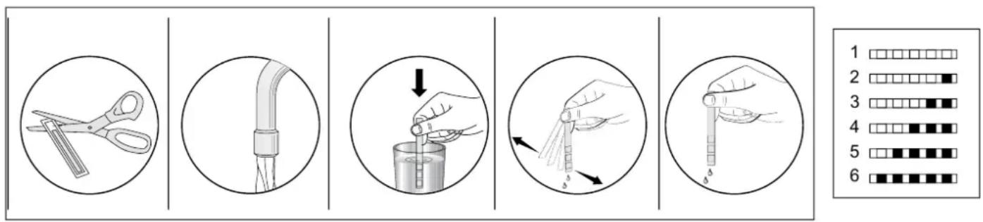
WATER HARDNESS
Adjust the water hardness setting of your machine according to the level specified on the test strip (if available).
In order to change the water hardness level, follow the steps below:
1) Turn on the machine and press the Program button for 5 seconds to enter water softener settings.
2) Press the Program button again to select the water hardness level (e.g. H3)
3) Change the water hardness level by pressing the Delay buttons, the setting will change in the following sequence: H1->H2->H3->H4->H5->H6
4) Press the Power button to save desired level: the newly selected level will stop flashing

WARNING
In order for the water softening system to work properly, the dishwasher must be filled with dishwasher salt before the first wash. See instructions in the salt dispenser chapter.
| LEVEL GERMAN °DH FRENCH °FH | BRITISH °CLARKE | REGENERATION OCCURS EVERY X PROGRAM SEQUENCE* | SALT CONSUMPTION (GRAM/ CYCLE) | ||
| H1 | 0–5 | 0–9 | 0–6 | No regeneration | 0 |
| H2 | 6–11 | 10–20 | 7–14 | 10 | 9 |
| H3 | 12–17 | 21–30 | 15–21 | 5 | 12 |
| H4 | 18–22 | 31–40 | 22–28 | 3 | 20 |
| H5 | 23–34 | 41–60 | 29–42 | 2 | 30 |
| H6 | 35–55 | 61–98 | 43–69 | 1 | 60 |
*Every cycle with a regeneration operation consumes additional 2.0 litres of water, the energy consumption increases by 0.02 kWh and the program extents by 4 minutes.
PLATE ARRANGEMENT
If you place your dishes into the machine properly, you will be using it in the best way in terms of energy consumption, washing and drying performance.
Into the lower basket, you can load round and deep items such as pots with long handles, pot lids, plates, salad plates, cutlery sets. The upper basket has been designed for dessert plates, salad bowls, cups and glasses. When placing long stem glasses and goblets, lean them against the basket edge, rack or glass supporter wire and not against other items. Do not lean long glasses against one another or they will lose their balance and may be damaged. It is more appropriate to place thin narrow parts into the middle sections of baskets. You can place spoons among other cutlery sets in order to prevent them from sticking to one another.

NOTE
Do not overload your dishwasher and pay attention to manufacturer instructions regarding dishes which are appropriate for use in a dishwasher. Only with suitable dishes (mentioned in section 5) will you obtain optimal washing results with a sensible use of energy.
High temperature water and dishwasher detergent may form a chemical synthesis that can damage certain items.

WARNING
Be careful when loading and unloading sharp items. Load sharp knives with the handles up to reduce the risk of personal injury.
We recommend that you use the cutlery grid for best results. To avoid possible injury, always place long-handled and sharp-pointed utensils such as serving forks, bread knives, etc., with their sharp points facing downwards or horizontally on the baskets.

WARNING
Place your dishes into your machine so that ^3) they will not prevent the upper and lower spray arms from spinning.
Follow the steps below before loading dishwasher.
1) Open the door.
2) Remove leftover food remains from tableware. It is not necessary to rinse the dishes under running water.
3) Load the dishwasher.

WARNING
Do not put into the appliance items that can absorb water (sponges, dishcloths).

NOTE
If you open the door while the appliance is running, all functions are automatically interrupted. Once the door is closed, functions will resume operation.

NOTE
Place all containers such as cups, glasses and pots into the dishwasher with the opening facing downwards (so that they cannot collect water).
When unloading the dishwasher, to prevent water dripping from the upper basket into the lower basket, it is recommended to empty the lower basket first, followed by the upper basket.

NOTE
Dishes and cutlery should not be placed above one another.

WARNING
Items will be hot! To prevent damage, do not take glass and cutlery out of the dishwasher for around 15 minutes after the program has ended.

NOTE
Very small items should not be washed in the dishwasher as they could easily fall out of the basket.
UPPER RACK
Load the upper rack with dessert plates, cups, glasses,
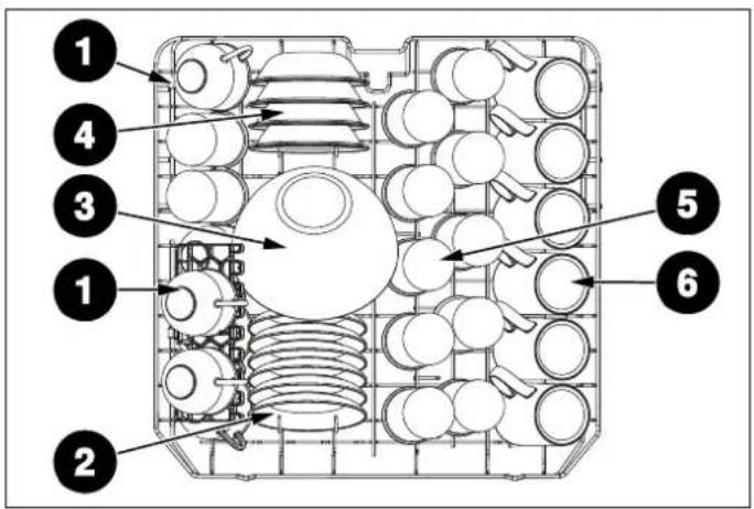
Fig. 25
| NUMBER ITEM | |
| 1 | Cups |
| 2 | Saucers |
| 3 | Glass bowl |
| 4 | Dessert bowls |
| 5 | Glasses |
| 6 | Mugs |
LOWER RACK
et into the lower basket, you can load round and deep items such as pots with long handles, pot lids, plates, salad plates, cutlery sets. The lower rack should not be used for small items such as cups, wine glasses.
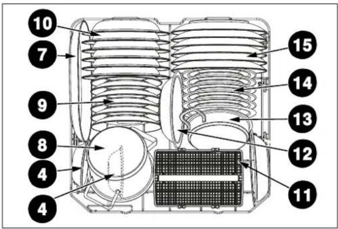
Fig. 26
| NUMBER ITEM | |
| 7 | Oval platter |
| 8 | Small pot |
| 9 | Dessert plates |
| 10 | Soup plates |
| 11 | Cutlery basket |
| 12 | Melamine bowls |
| 13 | Oven pot |
| 14 | Melamine dessert plates |
| 15 | Dinner plates |

NOTE
Place all large and very dirty items in the lower rack.

WARNING
Large knives and other utensils with sharp tips and edges must be placed horizontally on the upper rack due to the risk of injury. Other smaller knives and sharp utensils should be placed sharp side down in the cutlery basket.

NOTE
Make sure that large items do not interfere with the rotation of the spray arms, and do not prevent the detergent dispenser from opening.

NOTE
Important Note for Test Laboratories
For detailed information required for tests according to EN normatives and a soft copy of the manual, please send the model name and serial number to the following address: dishwasher@standardtest.info
SILVERWARE BASKET (DEPENDING ON MODEL)
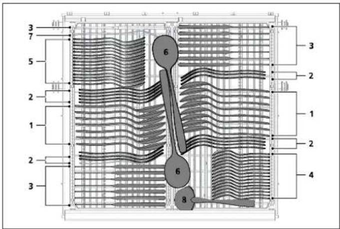
THIRD RACK (DEPENDING ON MODEL)
Fig. 28
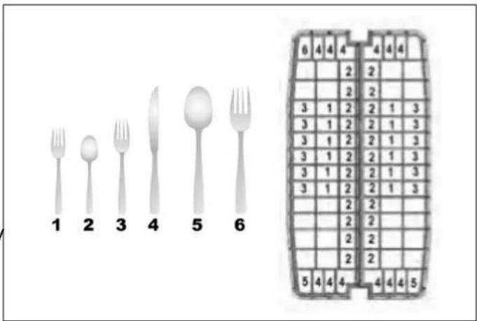
Cutlery should be placed in the cutlery rack separately from 1) Salad forks each other in the appropriate positions, and make sure 2) Teaspoons utensils do not nest into each other, as this may cause poor performance. For top quality cleaning, place the silverware 3) Dinner forks in the basket making sure that: 4) Knives
• They do not nest into each other.
- Load silverware with pointed and sharp sides downwards.
- Long utensils are in the middle.
Cutlery Basket load pattern for 12 place settings.

WARNING
Sharp cutlery may shift position during the wash cycle, and may be also wet and slippery. Take care when removing them to prevent injury.

NOTE
Small items should therefore be placed in the cutlery tray or cutlery basket (depending on model), as small items can fall from the baskets through the holders.
Fig. 27
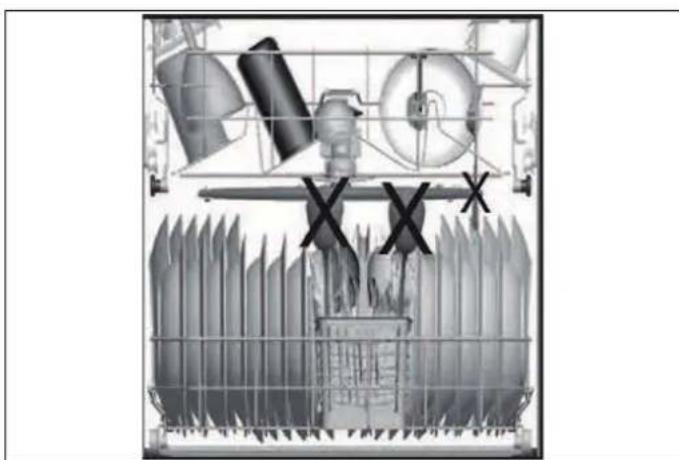
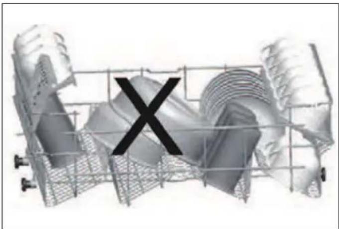
- Incorrect loading can cause poor washing and drying performance. Please follow the manufacturer recommendations for good results.
natural_image
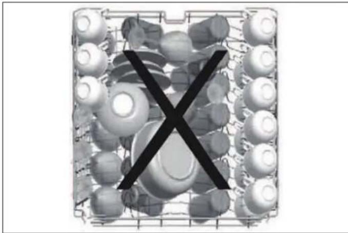
Black X symbol on a grid of circular objects, no text or symbols presentFig. 29
- Please do not overload your dishwasher. This is important for good results and for reasonable consumption of energy.
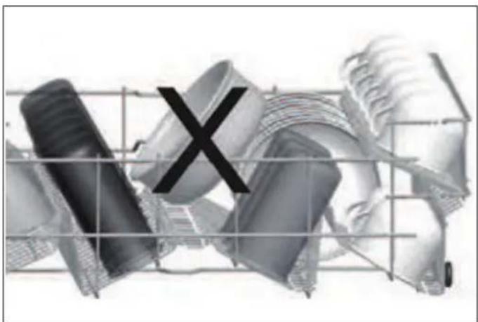
natural_image
Abstract 3D rendering of mechanical parts with a large 'X' symbol overlay (no text or symbols present)Fig. 31
natural_image
Cross-sectional diagram of a kitchen appliance showing internal components and fan base (no text or labels)Fig. 30
natural_image
3D rendered mechanical component with a central 'X' mark, no visible text or symbolsFig. 32
WHAT SHOULD NOT BE WASHED IN YOUR DISHWASHER?
- All items to be placed in the dishwasher should be dishwasher-safe.
- Only plastics with "dishwasher safe" or equivalent label may be placed in dishwashers. Plastics may lose their shape or color. Check with the manufacturer for recommendations.
- Any dishes made out of wood, or that include wooden parts, are not suitable for washing in dishwashers. High temperatures can cause the wood to swell or crack.
- Silver items without a "dishwasher safe" label should not be washed in the dishwasher as high temperatures and detergent can damage the silver. Check with the manufacturer for recommendations.
- "Dishwasher safe" silver items and stainless steel items should not come into contact, as the silver can become discolored.
- Porcelain and glassware with decorations and hand-painted utensils may lose their color and patterns due to the high temperatures. Non-decorated items are dishwasher-proof. Check with the manufacturer for recommendations.
- Aluminum can turn dark in the dishwasher due to the heat, the detergent used or even just certain minerals in your water.
- Do not wash sponges or dishcloths in the dishwasher.
- Do not wash any materials such as acrylic, copper, brass, pewter, iron, bronze or tin.
- Pots without a non-stick coating are safe to be cleaned by your dishwasher but some non-stick pots and pans can lose their coating and also sticking ability.
- Glued dishes or cutlery are not suitable for machine washing since adhesives that join materials such as plastic, wood, bone, steel, copper, tin, etc., may loosen.
• Crystal glass should not be washed in the dishwasher.
Remember, if you have any questions or concerns regarding items to be washed in the dishwasher, follow the instructions of the items' manufacturers, or wash the items by hand.

WARNING
If in doubt, wash by hand, or follow the instructions from the manufacturer of the utensils, dishes, glasses or pots and pans. Do not wash items soiled with cigarette ash, candle wax, varnish, paints or chemicals since they can damage your dishwasher.

WARNING
Empty the lower rack first and then the upper rack. This will avoid water dripping from the upper rack onto dishes in the lower rack.

WARNING
In general, it is not advisable to open the door while the dishwasher is in operation. If the door is opened, a safety device stops the dishwasher. Care should be taken when opening the door immediately following the cycle, as steam may escape.
RACKS
UPPER BASKET FOLDING TINES AND ÉTAGÈRES
The étagères are designed to increase the capacity of the top basket. You can place cups and glasses on these. Thanks to the adjustable nature of the étagères, you can place glasses of different sizes under them.
Height-adjustable étagères mounted on the basket allow mug and glass shelves to be in 2 different positions.
You can also place long knives, forks and spoons on the étagères horizontally so they do not to block the movement of the spray arms.

natural_image
3D wireframe diagram of a grid structure with directional arrows indicating flow or movement (no text or symbols)Fig. 33

natural_image
3D wire mesh structure with a cylindrical component inserted, showing internal structure and an arrow indicating rotation (no text or symbols)Fig. 34
The horizontal wire located on the top basket allows you to place your plates and bowls where required. You can also wash kitchenware such as pots or pans by closing the folding tines.

NOTE
Bringing the wires to the horizontal position by holding them from the ends may cause them to bend. It is therefore a good idea to bring the wires in the middle to the horizontal or vertical position by holding them from their stems and pushing.

NOTE
Make sure that both levers catch in the same height position.
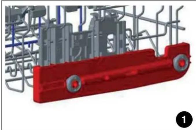
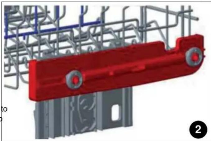
1) Height adjustment with load (depending on model)
The upper basket includes a mechanism that allows the height of the basket to be adjusted to the upper (1), lower (2) or middle (3) position without having to remove the basket. Grasp the basket on both sides and pull it up or down, ensuring that both sides of the upper basket are in the same position.
natural_image
3D rendered mechanical component with red and gray parts, no visible text or symbolsFig. 35
natural_image
3D rendering of a red mechanical component mounted on a metal frame structure (no text or symbols visible)Fig. 36
natural_image
3D rendering of a red mechanical component with circular ports, surrounded by steel framework and gray components (no text or symbols visible)Fig. 37
• Pull out the rack completely, B.
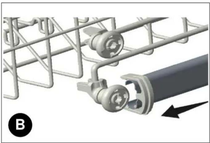
natural_image
Mechanical assembly diagram showing a coiled wire mesh and a cylindrical component with a black arrow indicating direction (no text or symbols)Fig. 39
2) Height adjustment without load (depending on model)
In certain models, the height setting of the upper rack may be changed using the wheels which are present at two height levels.

CAUTION
Make sure that the rack is empty. Changing the height setting while the rack contains tableware could cause the contents to dislodge, causing personal injury or damage to the tableware.
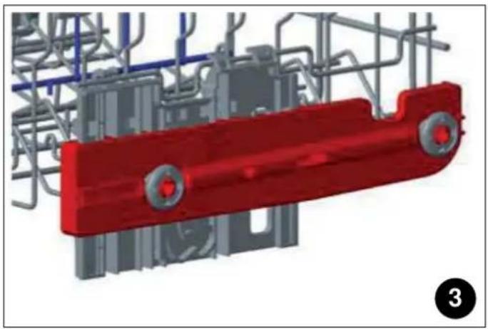
- Release the latches on both the right and left tracks of the upper rack by turning them outwards, A.
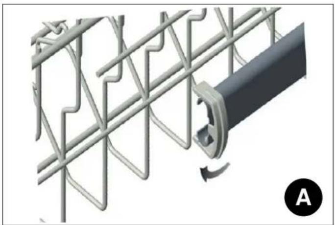
natural_image
Mechanical assembly diagram showing a meshed metal frame connected to a cylindrical component with a curved arrow indicating rotation (no text or symbols)Place the rack into the tracks again at the desired height, C.
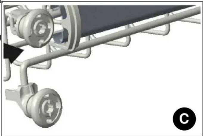
natural_image
Mechanical assembly diagram showing a shaft and wheel assembly with no visible text or symbolsFig. 40
- Push the latches back into the correct position.
Fig. 38
LOWER BASKET FOLDING TINES
SILVERWARE TRAY (DEPENDING ON MODEL)
Folding tines consist of four parts located on the lower basket of your machine, and are designed to make it eas
to place big items such as pots, pans, etc. If necessary, each part can be folded separately, or all of them can be folded and larger spaces can be obtained. You can use folding tines by raising them upwards, or by folding them.
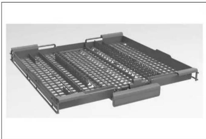
The silverware tray is designed for you to place forks, soons and knives, long dippers and small items.
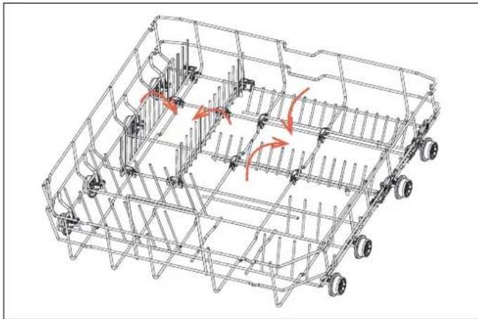
natural_image
3D wireframe model of a multi-wheeled vehicle chassis with no visible text or symbolsFig. 41
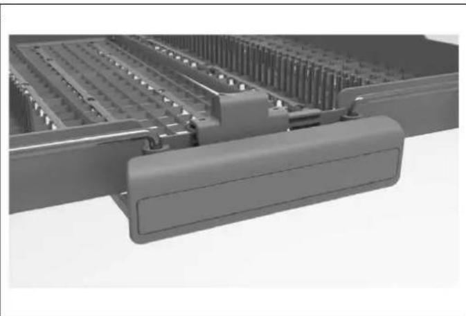
natural_image
3D rendering of a mechanical assembly with no visible text or symbolsFig. 43
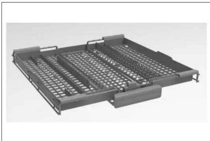
The silverware tray is composed of three pieces; if you need to space for the dishes in the upper basket, you can slide the left or right part of the upper cutlery basket in order to obtain more space.
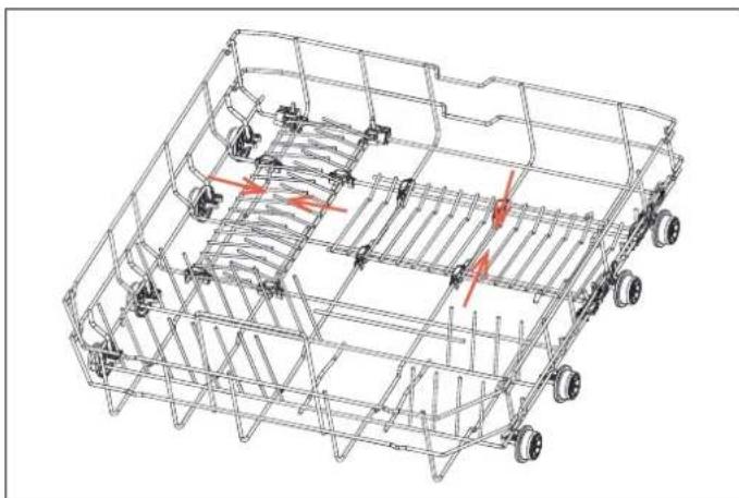
natural_image
Technical line drawing of a multi-wheeled vehicle chassis with visible structural components and red directional arrows indicating motion (no text or symbols)Fig. 42
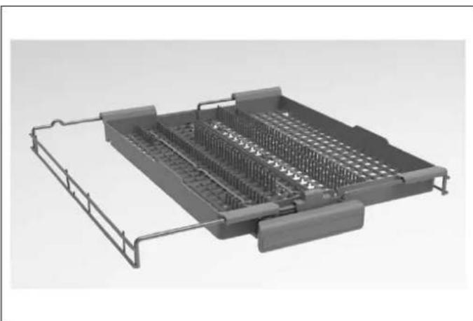
natural_image
3D rendering of a mechanical tray with internal grid structure (no text or symbols)Fig. 44
The middle part of the tray can be movable down and upSBVERWARE BASKET (DEPENDING ON MODEL) obtain more space
natural_image
3D rendering of a mechanical tray with internal grid structure (no text or symbols)Fig. 45
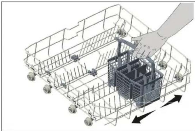
- The silverware basket is designed to wash knives, forks, spoons, etc. - According to the model purchased, you may have a sliding basket, or a standard one.
natural_image
3D wireframe illustration of a shopping cart with a hand adjusting its basket (no text or symbols)Fig. 47

WARNING
Knives and other sharp objects must be placed horizontally in the cutlery basket.
natural_image
3D rendering of a mechanical tray with grid-like internal structure (no text or symbols visible)Fig. 46
BOTTLE HOLDER (DEPENDING ON MODEL)
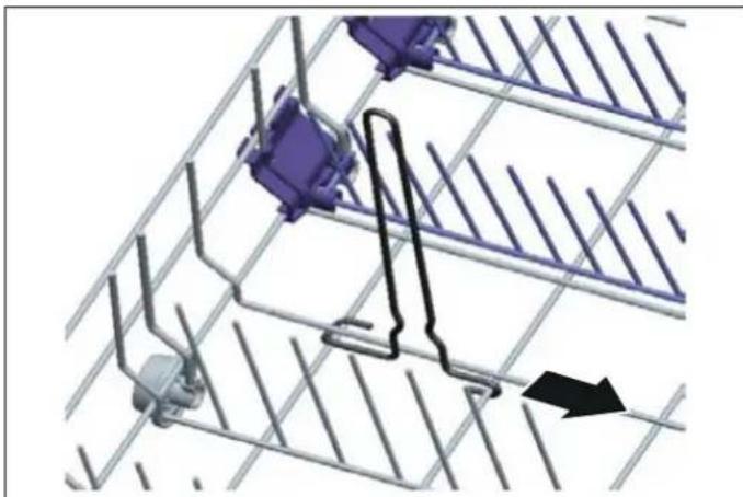
The bottle rack lets you wash large open containers, such as bowls, pans, or Tupperware, as well as tall items, such as jugs. The bottle rack can be pulled out in the direction of the arrow, as shown below.
natural_image
3D diagram of a mechanical assembly with purple components and metal grid lines, no visible text or symbolsFig. 48
TRAY HOLDER (DEPENDING ON MODEL)
The tray holder lets you easily place trays and pots of various sizes in the lower basket and provide the best washing performance.
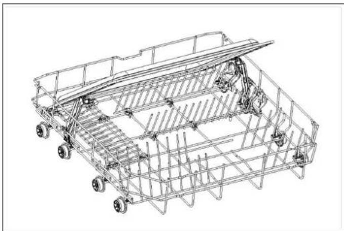
natural_image
Line drawing of a wireframe agricultural machine with multiple wheels and structural supports (no text or symbols)Fig. 49
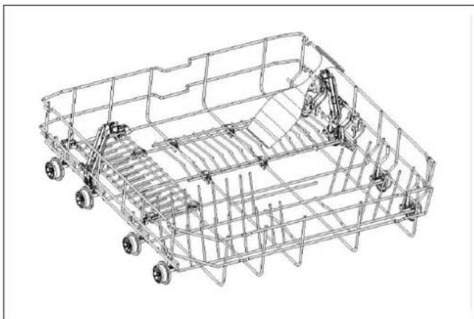
natural_image
Technical line drawing of a wheeled vehicle chassis frame with structural ribs and wheels (no text or symbols)Fig. 50
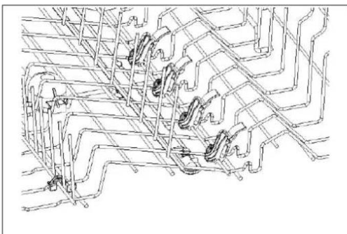
DIRECT WASH ZONE (DEPENDING ON MODEL)
This function is used to wash glasses, bottles and the like by directing the water upwards when the apparatus in the upper basket shown in the figure is in the vertical position. When the apparatus is in the horizontal position, the water goes down, which allows the lower basket to be washed.
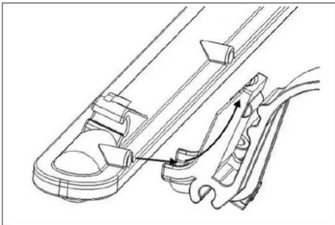
natural_image
Technical line drawing of a mechanical assembly with no visible text or symbolsFig. 51
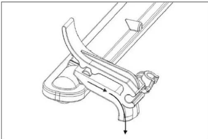
natural_image
Technical line drawing of a mechanical clamp or bracket assembly (no text or symbols)Fig. 52
natural_image
Pure technical line drawing of mechanical components without any text, numbers, or symbolsFig. 53
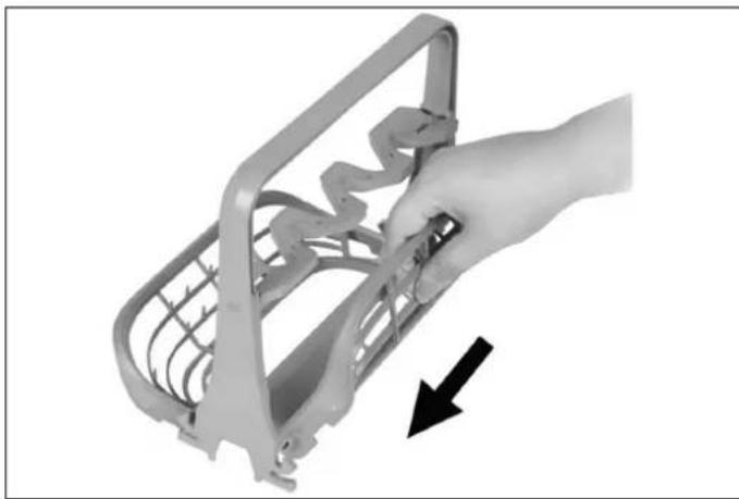
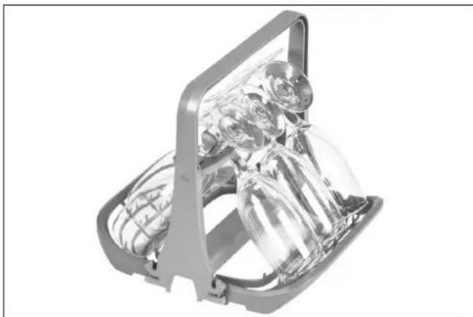
STEMWARE HOLDER (DEPENDING ON MODEL)
natural_image
Hand holding a metal bracket with internal wiring, pointing to a black arrow (no text or symbols visible)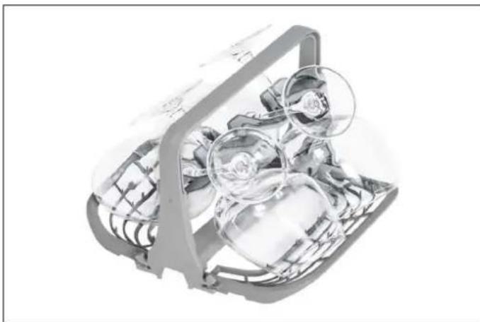
natural_image
Cross-sectional illustration of a mechanical device with internal components (no visible text or symbols)Fig. 56
Fig. 54 Unfold the stemware holder before placing it on the dishwasher's lower rack.
The sides of the stemware holder can be folded up so as to make the accessory more compact for storage when not needed.
natural_image
3D rendered illustration of a transparent plastic device with internal components (no text or symbols visible)Fig. 55
CONTROL PANEL
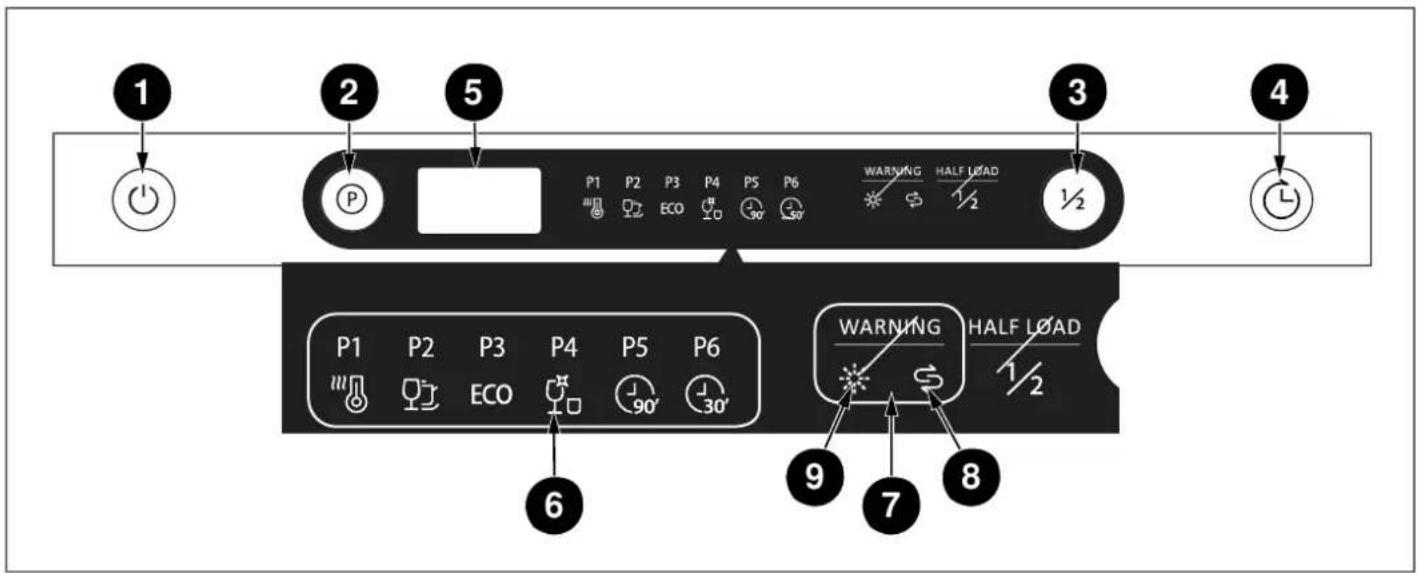
Fig. 57
1) On/Off Button
2) Program Buttons
3) Half Load
4) Delay Start
5) Display
6) Program Indicators
7) Warning Indicators
8) Salt Indicator
9) Rinse Aid Indicator
OPERATION
Setting a wash cycle
1) Press the button for the desired wash cycle. Cycle number will appear on the display.
2) Press Start/Pause and close the door. The cycle will start right after.
3) The display shows total time of the selected cycle and the remaining time during operation.
Changing a cycle
To change the wash cycle while the dishwasher is running, open the door and press the Program button for 3 seconds to select a new cycle, then press the Start/Pause button. After closing the door, the newly selected cycle will resume the course of the old one.

NOTE
A program can only be changed if it has been running only for a short period of time, otherwise the detergent may have already been released or the wash water with detergent has already been drained. If this is the case, the dishwasher needs to be reset and the detergent dispenser must be refilled
Pausing a cycle
A forgotten dish can be added any time before the detergent dispenser opens. If this is the case, follow the instructions below:
1) Open the door a little to stop the washing cycle
2) After the spray arms stop spinning, open the door completely
3) Add forgotten dishes
4) Close the door and dishwasher will resume its operation after 10 seconds

WARNING
It is dangerous to open the door mid-cycle, as hot steam may escape from the dishwasher. Always be cautious and open the door ever so slightly first, then fully only after a few minutes.
Switching the dishwasher off
When the selected program is completed, the buzzer will also sound 5 times. You can then switch your machine off using the Power On/Off button. Disconnect the plug and turn off the water tap.

NOTE
If the power is cut off during the drying process, the program will terminate. Your machine will be ready for a new program selection.
WASH CYCLES
| CYCLE PROGRAM # DESCRIPTION CYCLE TIME | WATER USAGE | POWER CONSUMPTION | ||
| Intensive | P1 | For heavily soiled items including pots and pans, even 3:25 with dried food residues. | 17,8 l/cycle 1,62 kWh/cycle | |
| Universal | P2 | For normally soiled loads, such as pots, plates, glasses 2:55 and lightly soiled pans. | 14,2 l/cycle 1,30 kWh/cycle | |
| Eco | P3 | For normally soiled dishes in typical everyday use. Lowest energy and water consumption. | 11,0 l/cycle 0,92 kWh/cycle | |
| Glass | P4 | For lightly soiled crockery and glass. | 14,2 l/cycle 1,10 kWh/cycle | |
| Rapid 90 min | P5 | For a quick wash of normally soiled daily dishes. | 11,5 l/cycle 1,35 kWh/cycle | |
| Rapid 30 min | P6 | For a quick wash of lightly soiled dishes. | 11,2 l/cycle 0,75 kWh/cycle | |

NOTE
The program duration may change according to the amount of dishes, the water temperature, the ambient temperature and selected additional functions.

NOTE
The Eco program is the most efficient program in terms of its combined energy and water consumption, and it is used to assess compliance with the EU eco design legislation (EN60436).
- Values given for wash cycles, other than the Eco cycle, are indicative.
- Only use powder detergent for short cycles.
- Short cycles do not include drying.
- To assist drying, we recommend slightly opening the door after a cycle is complete.
- You can access the product database where the model information is stored by reading the QR code on the energy label.
WASH CYCLES FLOW CHART
| INTENSIVE | UNIVERSAL | ECO | GLASS | RAPID 90 MIN | RAPID 30 MIN |
| Prewash (50°C) | Prewash (45°C) | Prewash | Prewash | - | - |
| Wash (65°C) | Wash (55°C) | Wash (45°C) | Wash (50°C) | Wash (60°C) | Wash (50°C) |
| Rinse | - | - | - | - | - |
| Rinse | Rinse | - | Rinse | Rinse | Rinse |
| Rinse (65°C) | Rinse (65°C) | Rinse (60°C) | Rinse (65°C) | Rinse (65°C) | Rinse (55°C) |
| Drying | Drying | Drying | Drying | Drying | - |
WASH OPTIONS
| OPTION DESCRIPTION ACTIVATION | ||
| Half Load Directs wash functions to both the upper and lower rack. Shortens the selected cycle wash time and reduces energy and water consumption. | Press the Half Load button to activate the Half Load option on both upper and lower racks. The corresponding indicator will also appear on the display. Press the Start/Pause button and close the door to activate the option. The option cannot be used with Rapid 30 min program. | |
| Delay Delays the start of the selected wash by 1-24 hours at 1-hour increments. | Press the Delay button to delay the cycle start time by 1 hour. The display will show cycle duration and programmed delay time alternately for 2 seconds. Continue to press Delay until you reach the desired delay time. The corresponding indicator will also appear on the display. Press the Start/Pause button and close the door to activate the option. | |
DETERGENT & RINSE-AID DISPENSER

WARNING
Only use detergents specifically designed for household dishwashers.
You can find powder, gel, and tablet detergents in the market that have been designed for household dishwashers. Add the proper detergent for the selected program to ensure the best performance. Use less detergent if the dishes are only lightly soiled. Using excess detergent can leave a film on dishes and in the dishwasher resulting in poor wash performance.

NOTE
The amount of detergent needed depends on the cycle, load size, and soil level of dishes. Too much detergent in soft water may cause glass corrosion and does not dissolve in water.

WARNING
Do not use too much detergent if your water supply is soft.

WARNING
Keep your detergents in a cool, dry place out of the reach of children. See the detergent manufacturer's instructions for further information.

WARNING
Detergent tablets do not fully dissolve with short programs. To prevent detergent residue on tableware, we recommend using tablets with long programs.

WARNING
Do not use detergent in the Rinse cycle (depending on model). If you do not know the hardness of your water supply, use 15 ml / 3 tsp detergent. Increase the amount of detergent if you see white watermarks, especially on the surface of glassware.
Should you need more information concerning the detergent you intend to use, contact the detergent manufacturers directly. is empty after the completion of each wash program.
FILLING THE DETERGENT

NOTE
The dispenser should be refilled just before the start of each program.
1) Push or slide to the right the latch to open the detergent container as shown in the image (Fig. A)
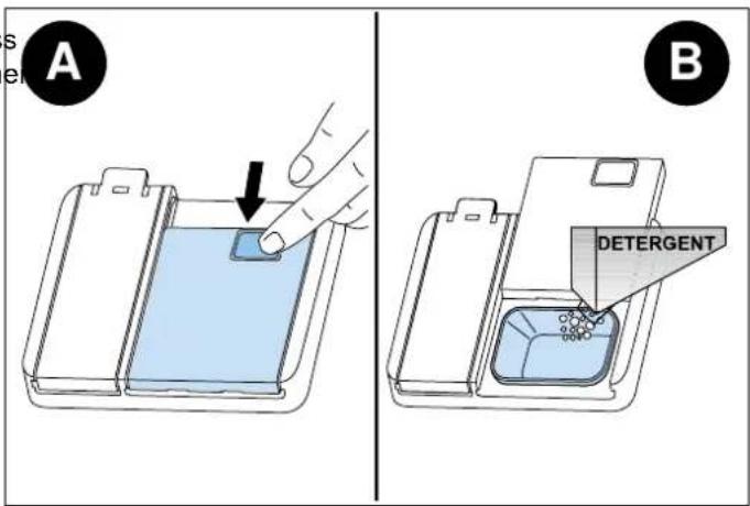
Fig. 58
2) Pour/put the detergent into the dispenser (Fig. B)
3) Close the lid and press it until it locks in place.

NOTE
If the dishes are heavily soiled, increase the dose of detergent. Alternatively, in addition to the detergent in the dispenser, pour a small amount of detergent on the inside of the door. The additional detergent will be activated during the pre-wash phase.

NOTE
The flap is always open at the end of a program.

WARNING
Follow the instructions on the detergent package when using liquid dishwasher detergent, concentrated powder detergent, or tablet detergent.

WARNING
Amounts may vary if you use liquid or concentrated powder detergent. Tablet detergents should be placed in the detergent container.
USING COMBINED DETERGENTS
Combined detergents must be used according to manufacturers' instructions.
Never put combined detergents inside the dishwasher's tubphase. or the cutlery basket.
Always put tablets in the detergent dispenser.
Combined detergents contain not only the detergent, but also rinse-aid, salt replacement substances and additional components depending on the combination.
If you stop using combined detergents, make sure that water hardness and rinse-aid settings are set to the correct level.
If you want to obtain better results while using combined detergents, add salt and rinse-aid into your machine and adjust the water hardness setting and the rinse-aid setting to the lowest position.

CAUTION
The solubility of the tablet detergents produced by different companies may vary depending on the temperature and time. Therefore, it is not recommended to use such detergents in short programs. Please use powder detergents in such programs.

WARNING
Should any problem, which you have not encountered before, arise with the use of this type of detergents, contact the detergent manufacturers directly.
RINSE-AID USAGE
Rinse-aid helps dry the dishes without streaks or stains. Rinse-aid is required for stain-free utensils and clear glasses and is automatically released during the hot rinse
If rinse-aid dosage is set too low, white stains will remain o glasses and dishes. If rinse-aid dosage is set too high, light blue stains will remain on glasses and dishes.

CAUTION
Only use rinse-aid intended for residential dishwashers.
Filling the rinse-aid dispenser with detergent will damage the dispenser.

NOTE
Your dishwasher is designed to use liquid rinse-aid.

NOTE
When the rinse-aid indicator lights up, the rinse-aid dispenser contains enough rinse-aid for 2 - 3 programs only. When using "Tab" detergents, rinse-aid is not needed.
Do not overfill the rinse-aid dispenser.
FILLING THE RINSE-AID AND SETTING
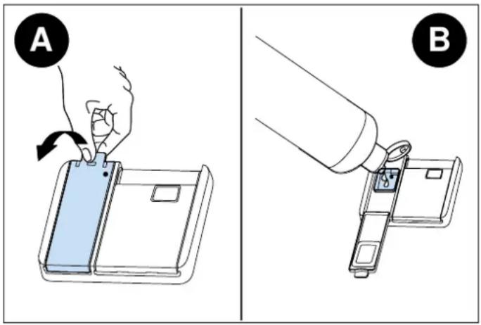
Fig. 59
1) To fill the rinse-aid compartment, open the rinse-aid compartment cap (Fig.A)
2) Fill the compartment with rinse-aid to the MAX level and then close the cap. Be careful not to overfill the rinse-aid compartment and wipe any spills.
3) Close the cap until it clicks.
In order to change the rinse-aid level, follow the steps below:
1) Turn on the machine and press the Program button for 5 seconds, then press the Delay button to enter Menu 3) settings: the Rinse Aid indicator will start flashing with a frequency of 1 Hz.
2) Change the rinse-aid level by pressing the Program button, the setting will change in the following sequence: D1->D2->D3->D4->D5->D1.
The factory setting is "4".

NOTE
If the dishes are not drying properly or are spotted, increase the level. If blue stains form on your dishes, decrease the level.
| LEVEL | BRIGHTENER DOSE | INDICATOR |
| 1 | Rinse-aid not dispensed | D1 is shown on the display. |
| 2 | 1 dose is dispensed | D2 is shown on the display. |
| 3 | 2 doses are dispensed | D3 is shown on the display. |
| 4 | 3 doses are dispensed | D4 is shown on the display. |
| 5 | 4 doses are dispensed | D5 is shown on the display. |
Exit Menu settings by waiting 5 seconds or turn the machine off.
SALT DISPENSER (FOR MODELS WITH WATER SOFTENER)
Please check the salt indicator on the control panel to see whether there is enough softening salt in the dishwasher. The salt dispenser must be refilled with salt whenever the salt warning indicator appears on the control panel of your machine.
FILLING THE DISHWASHER SALT DISPENSER

WARNING
Cooking and table salts do not dissolve in water easily, using these kinds of salts will damage the water softener system of your machine.
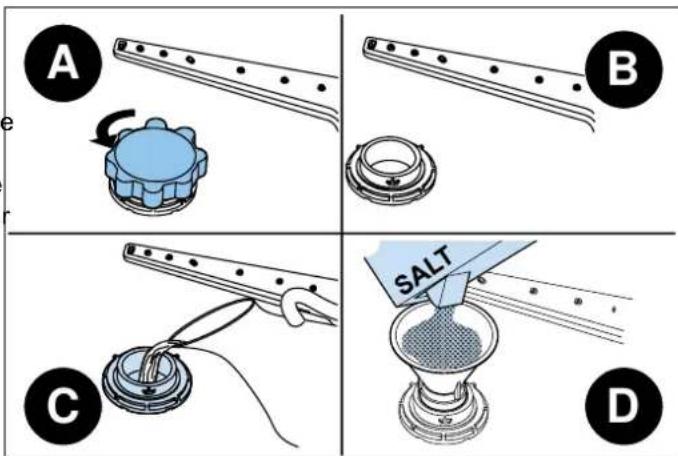
Fig. 60

NOTE
The machine can only use special dishwasher salt to soften the water. Do not 2) use any small-grained or powder-type salts which are easily soluble. Using any other type of salt can damage your machine. The manufacturer is not liable for damages resulting from using the wrong type of salt.
1) To fill the dishwasher with salt, first remove the lower basket and then open the salt compartment cap by turning it counterclockwise. (Fig. A-B)

WARNING
If the softener salt has overflowed and you do not start the machine immediately, run a short washing program to protect your machine against corrosion. These types of damages are out of warranty.

WARNING
Dishwasher detergent will damage the softener assembly. Do not fill the salt container with dishwasher detergent.

WARNING
If the water in your area is very soft and consistently lower than 9 °F you do not have to add dishwasher salt.

NOTE
Fill the salt compartment with water only the first time you fill the salt compartment.

NOTE
If the salt warning lamp on the control panel lights up, fill the salt compartment with salt again.

WARNING
Use softener salt specifically made for use in dishwashers.
SALT REFILL INDICATOR

WARNING
If the salt indicator light comes on during a program, wait until the end of the program to fill the salt dispenser with dishwasher salt. After the salt dispenser has been filled, the refill indicator may still be lit up if the salt concentration has not yet reached the correct level. It will go out when the correct concentration is reached.

NOTE
The salt refill indicator will turn off if you have programmed the dishwasher for a water hardness below 9 °F.
The salt dispenser should be refilled after every 20-30 cycles (approx. 1,5 kg).

WARNING
Before cleaning or carrying out maintenance, switch off the appliance, disconnect the mains plug and turn off the water tap. Your dishwasher can only be repaired by an authorized service agent.

WARNING
All surfaces are susceptible to scratching. Contact with unsuitable cleaning agents can alter or discolor all surfaces.

WARNING
Keep the floor around your dishwasher clean and dry to prevent any possible injury. We recommend keeping your dishwasher clean, empty and with door cracked open to allow air to circulate in case of any extended unused time.
The dishwasher door can be damaged by abrasive cleaners, scouring pads, abrasive cloths. Cleaning the machine at regular intervals prolongs the machine's service life.
Oil and limescale may accumulate in the machine's washing section. In case of such accumulation, fill the detergent compartment without loading any dishes into the appliance, select a program that runs at a high temperature, and start the dishwasher. If not enough, use special cleansing agents available on the market.
To clean any residue that has accumulated in the door seals, wipe the seals regularly using a damp cloth.
Clean the appliance, filter, and spray arms at least once a month. Unplug your machine and turn off its tap before cleaning. Do not use hard materials when cleaning your machine. Wipe with a soft cleaning material and a damp cloth.

WARNING
To avoid water infiltration in the door lock and electrical components, do not use a spray cleaner of any kind directly on the dishwasher.
| MATERIAL | PROCEDURE |
| Stainless steel | Use a non-abrasive steel detergent and apply with a soft lint-free cloth. To bring out the natural luster, lightly wipe surface with a water-dampened microfiber cloth followed by a dry polishing chamois. Always follow the grain of the stainless steel. |
| Control panel | Wipe with a damp cloth. |
| Dishwasher racks | Wipe with a damp cloth. |
| Interior | Wipe interior, door edge, and rubber seal with a damp cloth. If necessary, spray household cleaner on the cloth. Do not spray directly on the door. Use a dishwasher cleaner (follow the instructions on the package) or place 1 cup of vinegar and 2 tbsp of baking soda in a container on the middle rack and run a Heavy Wash cycle. |
| Spray arms | Place under running water and use a paper clip or similar to remove debris from holes. |
| Filter | Clean with soap and water. For hard-to-remove soils or calcium deposits, use a soft brush. Do not use a wire brush or scouring pad. |
| Gasket | Wipe with a damp cloth. Use warm soapy water and a toothbrush. If mold or mildew are present, spray with 3% hydrogen peroxide. |
After every wash, it is recommended to close the water supply of the appliance and leave the door slightly open for a while so that moisture and odours do not get trapped inside.
When you plan to not use the dishwasher for a long period of time, it is recommend to run a wash cycle with the dishwasher empty and then remove the plug from the socket, turn off the water supply and leave the door of the appliance slightly open. This will help the door seals to last longer and prevent odours from forming within the appliance.
If the appliance must be moved, try to keep it in a vertical position. If absolutely necessary, it can be positioned on its back.
SPRAY ARMS
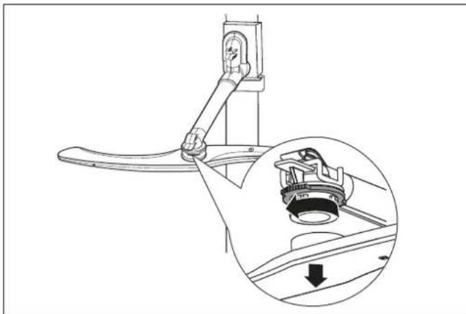
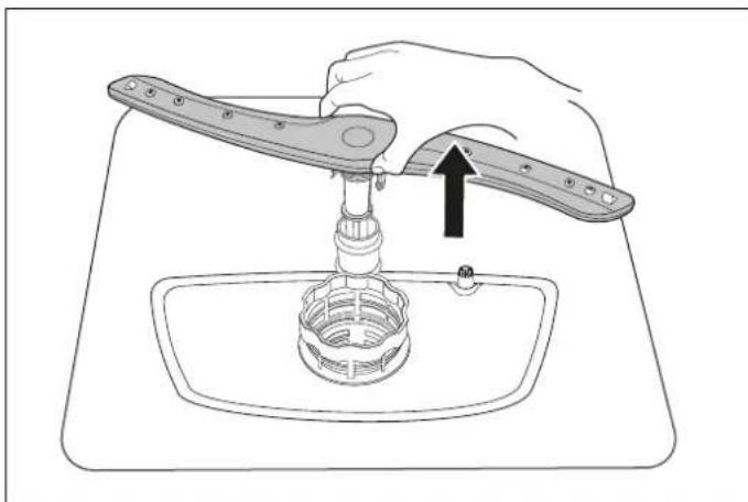
The upper and lower spray arms can be removed for cleaning.
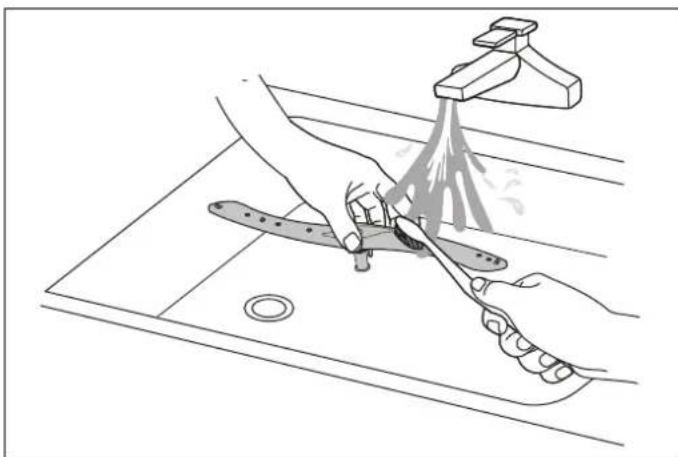
Periodically check whether the holes for the upper and lower spray arms are clogged. If you see any clogging, remove the spray arms and clean them under running water.
The impellers should be cleaned once a week for the appliance to operate efficiently.
To remove the lower spray arm:
1) Hold the nut, rotate the arm clockwise to remove it.
natural_image
Technical line drawing of a mechanical lever assembly with an inset showing a close-up of the component (no text or symbols)Fig. 61
To remove the upper spray arm:
1) Pull out the spray arm upward.
natural_image
Line drawing of a hand using a tool to lift a sink into a basin, with an arrow indicating the process (no text or symbols present)Fig. 62
2) Wash the arms in soapy and warm water and use a sof brush to clean the jets. Replace them after rinsing them thoroughly.
natural_image
Line drawing of a kitchen sink with hand cleaning the surface and a tool on the drain (no text or symbols)Fig. 63
FILTER
The filter should be cleaned often. Heavy use may require large food residues or foreign objects which were not more frequent cleaning. captured by the filters may block the waste water pump. The rinsing water will then be above the filter.
Periodically check whether there is any food waste left on the coarse and fine filters. If there is any food waste left, remove the filters, and clean them thoroughly under running water.
To take out the filter from the dishwasher, first remove the lower rack and lower spray arm.
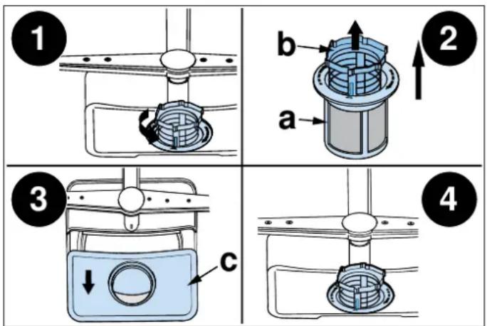
Fig. 64
a. Micro Filter
b. Coarse Filter
c. Metal/Plastic Main Filter
1) Hold the coarse filter and rotate it anticlockwise to unlock the filter. Lift the filter upwards and out of the dishwasher.
2) The micro filter can be pulled off the bottom of the filter assembly. The coarse filter can be detached from the main filter by gently squeezing the tabs at the top and pulling it away.
3) Larger food residues can be cleaned by rinsing the filter under running water. For a more thorough clean, use a soft cleaning brush.
4) Reassemble the filters in the reverse order of the disassembly, replace the filter insert, and rotate clockwise to the close arrow.

WARNING
Do not over tighten the filters. Put the filters back in sequence securely, otherwise coarse debris could get into the system and cause a blockage.

WARNING
Never use the dishwasher without filters in place. Improper replacement of the filter may reduce the performance level of the appliance and damage dishes and utensils.
DRAIN PUMP
Large food residues or foreign objects which were not captured by the filters may block the waste water pump. The rinsing water will then be above the filter.

WARNING
Warning Risk of cuts
When cleaning the waste water pump, ensure that you do not injure yourself on pieces of broken glass or pointed implements.
In this case:
1) First always disconnect the appliance from the power supply.
2) Take out baskets.
3) Remove the filters.
4) Scoop out water, use a sponge if required.
5) Check the area and remove any foreign objects.
6) Install filters.
7) Re-insert baskets.
FAULT POSSIBLE CAUSE TROUBLESHOOTING
| The program does not start. | Your dishwasher is not plugged in. Plug your dishwasher in. | |
| Your dishwasher is not switched on. | Switch your dishwasher on by pressing the On/Off key. | |
| Fuse blown. | Check your indoor fuses. | |
| Water inlet tap is closed. Turn on the water inlet tap. | ||
| Your dishwasher door is open. | Close the dishwasher door. | |
| Water inlet hose and machine filters are clogged. | Check the water inlet hose and machine filters and make sure they are not clogged. | |
| Water pressure is low. | Check that the water supply is connected properly and the water is turned on. | |
| Water remains inside the machine. | Water drain hose is clogged or twisted. | Check the drain hose, then either clean or untwist it. |
| The filters are clogged. | Clean the filters. | |
| The program is not finished yet. Wait until the program is finished. | ||
| The kitchen sink is clogged. | Check the kitchen sink to make sure it is draining well. If the problem is the kitchen sink that is not draining, you may need a plumber rather than a serviceman for dishwashers. | |
| Machine stops during washing. | Power failure. | Check mains power. |
| Water inlet failure. | Check water tap. | |
| There is foam in the tub. | Wrong detergent. | Only use dishwasher detergent. |
| Open the dishwasher and let suds evaporate. | ||
| Add 1L of cold water to the bottom of the dishwasher. Close the dishwasher door, then select any cycle. Initially, the dishwasher will drain out the water. Open the door after draining stage is complete. | ||
| Spilled rinse-aid. | Always wipe up spills immediately. | |
| Rattling noise during a wash cycle. | Items of crockery are loose in the dishwasher. | Interrupt the program and rearrange the items of crockery. |
| Shaking and bumping noises are heard during a wash cycle. | The spray arm is hitting the dishes in move or remove items blocking the lower basket. | Move or remove items blocking the spray arm. |
FAULT POSSIBLE CAUSE TROUBLESHOOTING
| Dishes are not clean. | Dishes placed incorrectly, sprayed water not reaching affected dishes. | Do not overload baskets. |
| Dishes leaning against each another. | Place dishes as instructed in the section on loading your dishwasher. | |
| Not enough detergent used. | Use the correct amount of detergent, as instructed in the program table. | |
| Wrong wash program selected. | Use the information in the program table to select the most appropriate program. | |
| Spray arms clogged with food waste. | Clean the holes in the spray arms with thin objects. | |
| Filters or water drain pump clogged filter misplaced. | Check that the drain hose and filters are correctly fitted. | |
| There are whitish stains left on the dishes. | Not enough detergent used. | Use the correct amount of detergent, as instructed in the program table. |
| Rinse-aid dosage and/or water softener setting set too low. | Increase rinse-aid and/or water softener level. | |
| High water hardness level. | Increase water softener level and add salt. | |
| Salt compartment cap not closed properly. | Check that the salt compartment cap is closed properly. | |
| Dishes do not dry. | Drying option is not selected. Select a program with a drying option. | |
| Improper loading of dishwasher. | Use gloves if detergent residue can be found on dishes to avoid skin irritations. Make sure to place cups and glasses at an angle against the wire cup tray in the upper basket. | |
| Rinse-aid dosage set too low. Increase rinse-aid dosage setting. | ||
| Dishes are removed too soon. | Do not empty your dishwasher immediately after washing. Open the door slightly so that the steam can come out. Take out the dishes until the inside temperature is safe to touch. Unload the lower basket first to prevent the dropping water from the upper basket. | |
| Black or grey marks on dishes. | Aluminium utensils have rubbed against dishes. | Use a mild abrasive cleaner to eliminate those marks. |
| Rust stains have formed on the dishes. | Stainless-steel quality of the dishes is insufficient. | Use only dishwasher-proof sets. |
| High level of salt in wash water. | Adjust the water hardness level using the water hardness table. | |
| Salt compartment cap not closed properly. | Check that the salt compartment cap is closed properly. | |
| Too much salt spilled in the dishwasher while filling it with salt. | Use funnel while filling compartment with salt to avoid spillage. | |
| Poor mains grounding. | Consult a qualified electrician immediately. | |
FAULT POSSIBLE CAUSE TROUBLESHOOTING
| Detergent remains in the detergent compartment. | Detergent was added when the detergent compartment was wet. | Make sure detergent compartment is dry before use. |
| Improper loading of dishwasher. | Use gloves if detergent residue can be found on dishes to avoid skin irritations. Make sure to place cups and glasses at an angle against the wire cup tray in the upper basket. | |
| Dishes are removed too soon. | Do not empty your dishwasher immediately after washing. Open the door slightly so that the steam can come out. Take out the dishes until the inside temperature is safe to touch. Unload the lower basket first to prevent the dropping water from the upper basket. | |
| Cloudiness on glassware. | Combination of soft water and too much detergent. | Use less detergent if you and select a shorter cycle to wash the glassware and to get them clean. |
AUTOMATIC FAULT WARNINGS
FAULT CODE POSSIBLE FAULT WHAT TO DO
| E1 | Longer water inlet time | Make sure the water inlet tap is open and water is flowing. |
| Separate the inlet hose from the tap and clean the hose filter. | ||
| Contact service if the error continues. | ||
| Make sure the water pressure is not too low for the appliance. | ||
| E3 | Water not reaching required temperature | Contact service. |
| E4 | Overflow | Unplug the machine and close the tap. |
| Contact service. | ||
| Ed | Failure of communication between main circuit board and display circuit board | Contact service. |
PRACTICAL INFORMATION
1) When the machine is not in operation:
- Disconnect the plug and close the tap.
- Leave the door slightly open to prevent the formation of odors.
2) Select the dry option to remove water droplets.
3) Place dishes in the machine properly to achieve the best energy consumption, washing and drying performance. Please see the program and consumption table for more information.
4) Rinse dirty dishes before placing them in the dishwasher.
5) Only use the Rinse program when necessary.
6) Do not place the machine near a refrigerator as it will reach high temperatures.
7) If the machine is located in an area at risk of freezing, close the tap, disconnect the inlet hose from the tap, and drain the water inside the hose and the machine completely.

Bertazzoni is committed to providing the highest quality service to our customers. In the unlikely event that your product should have a manufacturing defect, please contact our service team at:
https://uk.bertazzoni.com/more/care-service
You will be requested to provide product information, proof of purchase, a photo of the silver data label and a description of the issue. Please have this information ready.
DALLA SCRIVANIA DEL PRESIDENTE
Gentile Cliente,
natural_image
Illustration of a hand cleaning a cabinet (no text or symbols)Fig. 11
natural_image
Illustration of a cabinet interior with a curved duct and a magnified inset showing a mechanical component (no text or symbols)Fig. 12

ATTENZIONE
natural_image
Architectural diagram of a building corner with yellow walls and gray walls (no text or symbols)Fig. 13
Fig. 15

NOTA
Fig. 14
natural_image
Technical line drawing of a door frame with mounting brackets and internal components (no text or symbols)Fig. 16
natural_image
Technical line drawing of a rectangular mechanical or architectural component with labeled sides (a and no), no readable text or symbols.Fig. 17
Fig. 19
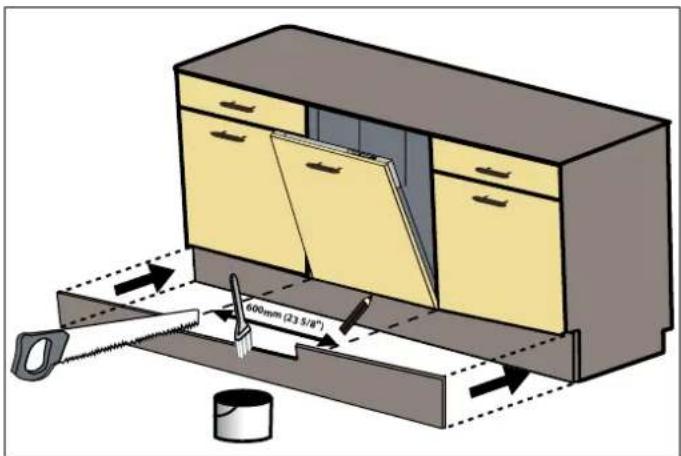
Fig. 21
natural_image
Technical diagram showing a mechanical assembly with an inset close-up of a screwdriver inserted into a gear mechanism (no text or labels present)Fig. 20
natural_image
Illustration of a kitchen appliance with a close-up view showing airflow direction (no text or symbols)Fig. 24
LISTA DI CONTROLLO PER L'INSTALLATORE
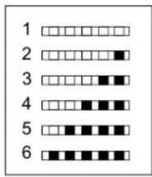
DUREZZA DELL'ACQUA
Fig. 26
natural_image
Diagram of a battery pack with a black 'X' symbol overlay (no text or labels)Fig. 29
natural_image
Abstract grayscale illustration of mechanical components with a 'X' symbol overlay (no text or symbols present)Fig. 31
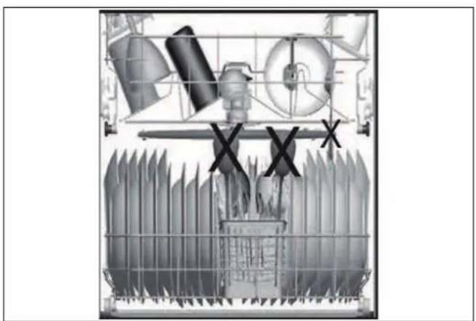
natural_image
Cross-sectional diagram of a washing machine showing internal components and fan blades (no text or labels)Fig. 30
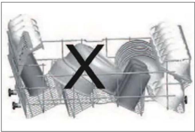
natural_image
3D rendered mechanical components with a black 'X' symbol overlay (no text or labels)Fig. 32
COSA NON SI DEVE LAVARE IN LAVASTOVIGLIE?
natural_image
3D wireframe diagram of a structural grid with rebar and anchor bolts, showing directional arrows (no text or symbols)Fig. 33
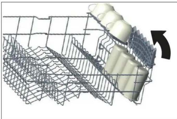
natural_image
3D wire mesh diagram of a mechanical component with internal structure and directional arrow (no text or symbols)Fig. 34
natural_image
3D rendered mechanical component with red and gray parts, no visible text or symbolsFig. 35
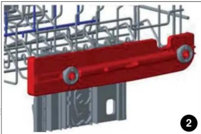
natural_image
3D rendering of a red mechanical component with gray structural elements and blue wiring (no text or symbols visible)Fig. 36
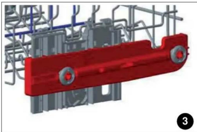
natural_image
3D rendering of a red mechanical component with gray structural elements and blue pipes (no text or symbols visible)Fig. 37
natural_image
Mechanical assembly diagram showing a metal frame with two circular components and a cylindrical shaft, no text or symbols present.natural_image
Mechanical assembly diagram showing a meshed metal frame connected to a cylindrical component with a rotating arrow (no text or symbols)Fig. 38
Fig. 39
natural_image
Mechanical assembly diagram showing a shaft with wheels and a valve mechanism (no text or symbols)Fig. 40
natural_image
Technical line drawing of a multi-wheeled vehicle chassis with structural ribs and wheels (no text or symbols)Fig. 41
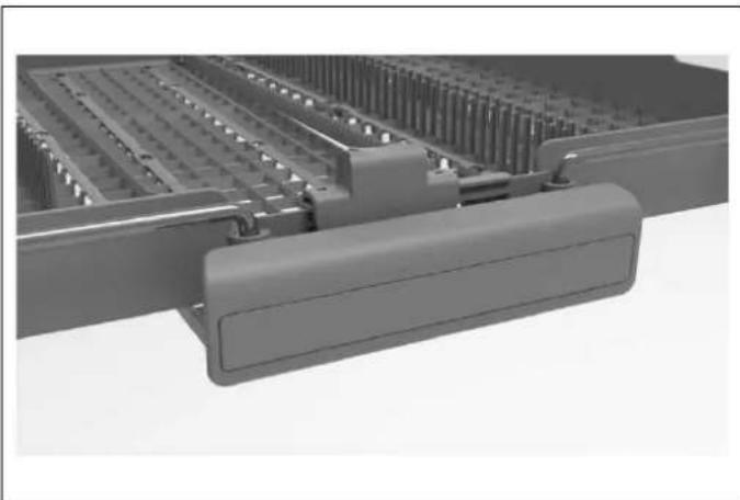
natural_image
3D rendering of a mechanical assembly with no visible text or symbolsFig. 43
natural_image
Technical line drawing of a vehicle chassis frame with no visible text or symbolsFig. 42

natural_image
3D rendering of a mechanical tray with internal grid structure (no text or symbols)Fig. 44
natural_image
3D rendering of a mechanical tray with grid-like internal structure (no text or symbols visible)Fig. 45

AVVERTENZA
natural_image
3D rendering of a mechanical tray or enclosure with grid-like internal components (no text or symbols visible)Fig. 46
iCESTELLO PORTAPOSATE (IN BASE AL MODELLO)
natural_image
3D wireframe diagram of a shopping cart with a hand operating it, showing internal components and directional arrows (no text or symbols)Fig. 47
PORTABOTTIGLIE (A SECONDA DEL MODELLO)
natural_image
3D diagram of a mechanical assembly with purple components and a black arrow indicating direction (no text or symbols)Fig. 48
PORTA VASSOI (A SECONDA DEL MODELLO)
natural_image
Technical line drawing of a wheeled agricultural machine with no visible text or symbolsFig. 49
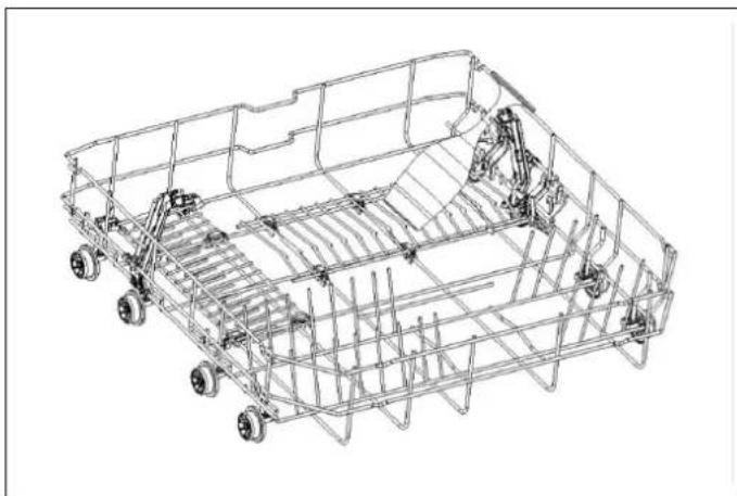
natural_image
Technical line drawing of a wheeled vehicle chassis frame with structural components (no text or symbols)Fig. 50
ZONA DI LAVAGGIO DIRETTO (A SECONDA DEL MODELLO)
natural_image
Technical line drawing of a mechanical component with no visible text or symbolsFig. 51
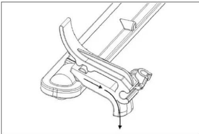
natural_image
Technical line drawing of a mechanical clamp or bracket assembly (no text or symbols)Fig. 52
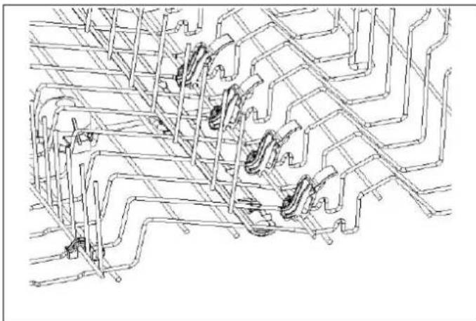
natural_image
Pure technical line drawing of a mechanical assembly without any text, numbers, or symbolsFig. 53
PORTABICCHIERI A STELO (A SECONDA DEL MODELLO)
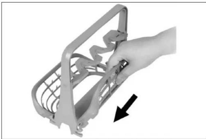
natural_image
Hand holding a metal bracket with a black arrow pointing to it, no text or symbols visibleFig. 54
natural_image
Cross-sectional view of a transparent plastic device with internal components (no visible text or symbols)Fig. 55
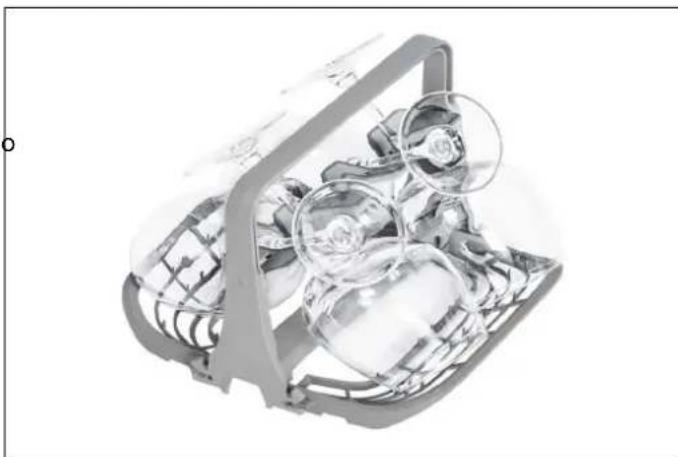
natural_image
Cross-sectional diagram of a mechanical device with internal components (no visible text or symbols)Fig. 56
When the selected program is completed, the buzzer will also sound 5 times. You can then switch your machine off Sul using the Power On/Off button. Disconnect the plug and turn off the water tap.

NOTA
Fig. 58

AVVERTENZA
natural_image
Technical line drawing of a mechanical lever assembly with an inset close-up showing a component detail (no text or symbols)Fig. 61
natural_image
Illustration of a hand using a tool to lift a sink into a basin, with an arrow indicating the process (no text or symbols present)Fig. 62
natural_image
Line drawing of hands using a tool to clean or wash a surface, no text or symbols presentFig. 63
FILTRO
Fig. 64
a. Micro filtro
b. Filtro grosso
c. Filtro principale in metallo/plastica
DÉCLARATION CE DE CONFORMITÉ 115
MISE AU REBUT DE VOTRE ANCIENNE MACHINE 115
MANUEL D'INSTALLATION 116
SPÉCIFICATIONS 116
ASPECT GÉNÉRAL 116
CARACTÉRISTIQUES TECHNIQUES 116
INSTALLATION 117
DIMENSIONS DE L'OUVERTURE 117
PANNEAU DE PORTE PERSONNALISÉ (POUR LES MODÈLES AVEC PANNEAU PERSONNALISÉ) . 117
CHARGEMENT DU LAVE-VAISSELLE 118
EXIGENCES ÉLECTRIQUES 119
EXIGENCES EN MATIÈRE DE PLOMBERIE 120
INSTALLATION 122
MANUEL D'UTILISATION ET D'ENTRETIEN 130
UTILISATION 130
DÉCLARATION CE DE CONFORMITÉ
natural_image
Illustration of a hand cleaning a cabinet (no text or symbols)Fig. 11
natural_image
Diagram showing a cabinet interior with a curved duct and a magnified inset of a device (no text or symbols)Fig. 12

ATTENTION !
natural_image
Architectural diagram of a roof structure with yellow walls and gray walls (no text or symbols)Fig. 13
MISE EN PLACE DU LAVE-VAISSELLE DANS LE MEUBLE D'ENCASTREMENT
Fig. 14
Fig. 15
natural_image
Technical line drawing of a door frame with internal components and mounting brackets (no text or symbols)Fig. 16
natural_image
Technical line drawing of a rectangular frame with two labeled points 'a' and internal features (no text or symbols beyond labels)Fig. 17
3.2) Fixez les quatre vis longues (b).
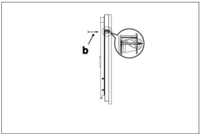
Fig. 18

NOTE
Fig. 19
Fig. 20
natural_image
Diagram showing a door lock mechanism with screwdrivers and a magnified inset of the lock component (no text or symbols)Fig. 22
ATTACHEMENT DE LA PLAQUE DE PROTECTION
natural_image
Diagram of a kitchen appliance with a 600-degree angle measurement and a diagonal saw (no text or symbols)Fig. 23
natural_image
Illustration of a kitchen appliance with a fan and ventilation system, showing airflow direction (no text or symbols)Fig. 24
LISTE DE CONTRÔLE DE L'INSTALLATEUR
CONSEILS D'AUTO-ASSISTANCE
natural_image
Simple line drawing of scissors and ruler inside a circle (no text or symbols)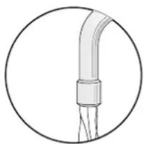
natural_image
Simple line drawing of a pipe fitting with a bulbous base, enclosed in a circle (no text or symbols)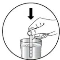
natural_image
Illustration of a hand pouring liquid into a beaker with a dropper (no text or symbols)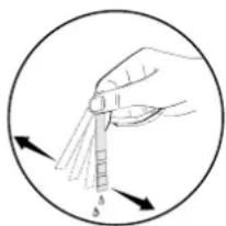
natural_image
Illustration of a hand holding a pipette with liquid droplets, enclosed in a circle (no text or symbols)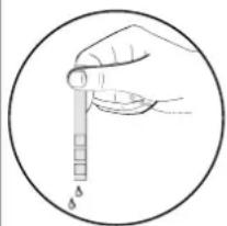
natural_image
Hand holding a pipette with a scale, enclosed in a circle (no text or symbols)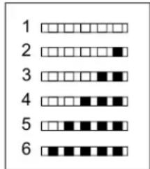
DURETÉ DE L'EAU
Fig. 25
NOMBRE ARTICLE
natural_image
Diagram of a battery pack with a black 'X' symbol overlay (no text or labels)Fig. 29
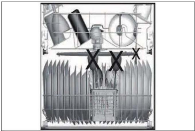
natural_image
Cross-sectional view of a mechanical or electrical component with no visible text or symbolsFig. 30
natural_image
Abstract grayscale illustration of mechanical components with a large 'X' symbol overlay (no text or symbols present)Fig. 31
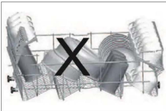
natural_image
3D rendered mechanical components with a central 'X' symbol, no text or labels presentFig. 32
QU'EST-CE QUI NE DOIT PAS ÊTRE LAVÉ DANS VOTRE LAVE-VAISSELLE ?
natural_image
3D wireframe model of a mechanical or structural assembly with internal components and directional arrows (no text or symbols)Fig. 33
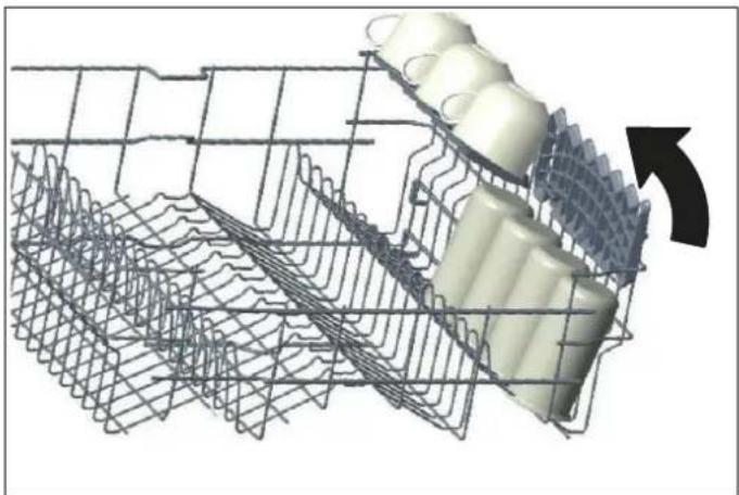
natural_image
3D wire mesh structure with a highlighted cylindrical component and an arrow indicating rotation (no text or symbols)Fig. 34
natural_image
3D rendered mechanical component with red base and gray structural framework (no text or symbols)Fig. 35
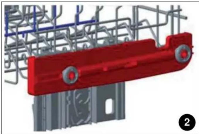
natural_image
3D rendering of a red industrial mechanical component with gray structural elements and blue piping (no text or symbols visible)Fig. 36
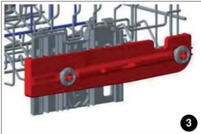
natural_image
3D rendering of a red industrial component with gray structural framework and blue pipes (no text or symbols visible)Fig. 37
natural_image
Mechanical assembly diagram showing a meshed metal frame with a rotating component and directional arrow (no text or symbols)Fig. 38
natural_image
Mechanical assembly diagram showing a coiled wire cage with two components and a shaft, no text or symbols present.Fig. 39
natural_image
Mechanical assembly diagram showing a conveyor belt system with rollers and shafts (no text or symbols)Fig. 40
natural_image
Technical line drawing of a multi-wheeled vehicle chassis frame with no visible text or symbolsFig. 41
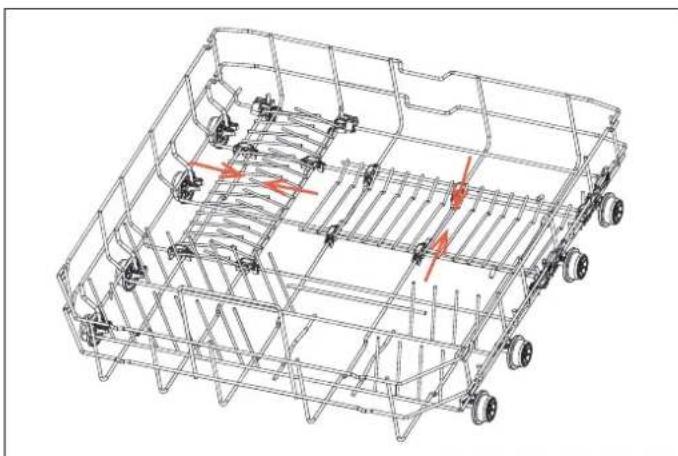
natural_image
Technical line drawing of a vehicle chassis frame with visible structural components and red directional arrows indicating motion or force (no text or symbols)Fig. 42
PLATEAU À COUVERTS (SELON LE MODÈLE)
natural_image
3D rendering of a mechanical component with multiple slots and a handle (no visible text or symbols)Fig. 43
natural_image
3D rendering of a mechanical tray with internal grid structure (no text or symbols)Fig. 44
natural_image
3D rendering of a mechanical tray with grid-like internal components (no text or symbols visible)Fig. 45

MISE EN GARDE
natural_image
3D rendering of a mechanical tray with grid-like internal structure (no text or symbols visible)Fig. 46
PANIER À COUVERTS (SELON LE MODÈLE)
natural_image
3D wireframe diagram of a shopping cart with wheels and a hand operating it, showing directional arrows (no text or symbols)Fig. 47
SUPPORT À PLATEAUX (SELON MODÈLE)
natural_image
Technical line drawing of a mechanical agricultural machine (no text or symbols visible)Fig. 49
SUPPORT À BOUTEILLES (SELON LE MODÈLE)
natural_image
3D diagram of a mechanical assembly with purple components and metal grid lines, no visible text or symbolsFig. 48
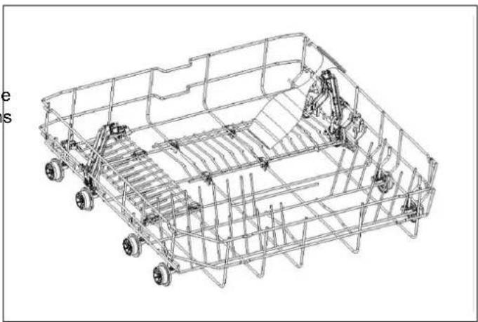
natural_image
Technical line drawing of a wheeled vehicle chassis frame with visible structural components (no text or symbols)Fig. 50
ZONE DE LAVAGE DIRECT (SELON LE MODÈLE)
natural_image
Technical line drawing of a mechanical assembly with no visible text or symbolsFig. 51
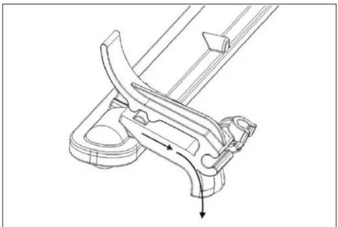
natural_image
Technical line drawing of a mechanical clamp or bracket assembly (no text or symbols)Fig. 52
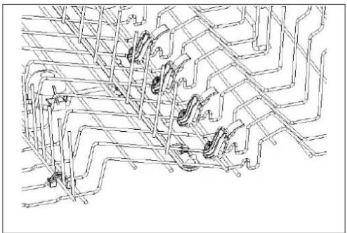
natural_image
Technical line drawing of a mechanical assembly with multiple brackets and mounting holes (no text or symbols)SUPPORT DE PORTE-VERRES À PIED (SELON MODÈLE)
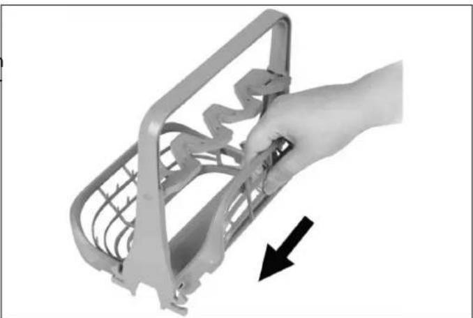
natural_image
Hand holding a metal cage with a black arrow pointing to the side (no text or symbols visible)Fig. 54
natural_image
3D rendered image of a transparent plastic device with internal components, no visible text or symbolsFig. 55
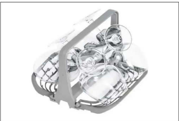
natural_image
Cross-sectional diagram of a mechanical device with internal components and no visible text or symbolsFig. 58
natural_image
Diagram of a mechanical device with an inset showing a close-up of the component (no text or symbols present)Fig. 61
natural_image
Illustration of a hand using a tool to lift a sink into a basin, with an arrow indicating the process (no text or symbols present)Fig. 62
natural_image
Line drawing of a kitchen sink with hand cleaning the surface using a tool (no text or symbols)Fig. 63
FILTRE
Fig. 64
INFORMATIONS PRATIQUES
MATERIAL SOM KAN KOMMA ATT BEHÖVAS
natural_image
Illustration of a hand cleaning a cabinet (no text or symbols)Fig. 11
natural_image
Illustration of a cabinet interior with a magnified inset showing a hand holding a tool, indicating airflow or movement (no text or symbols present)Fig. 12

OBSERVERA
natural_image
Architectural diagram showing a window frame with yellow walls and gray panels (no text or symbols)Fig. 13
ATT PLACERA DISKMASKINEN I ÖPPNINGEN
Fig. 14
Fig. 15
natural_image
Technical line drawing of a door frame with mounting brackets and internal components (no text or symbols)Fig. 16
natural_image
Technical line drawing of a rectangular mechanical or architectural component with two labeled corners (a), no text or symbols present.Fig. 17
Fig. 19
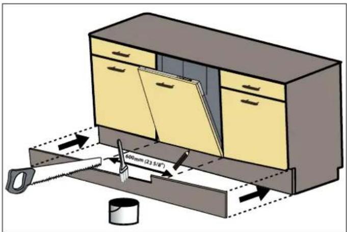
Fig. 21
natural_image
Technical diagram showing a mechanical assembly with an inset close-up of a tool interacting with a component (no text or symbols present)Fig. 20
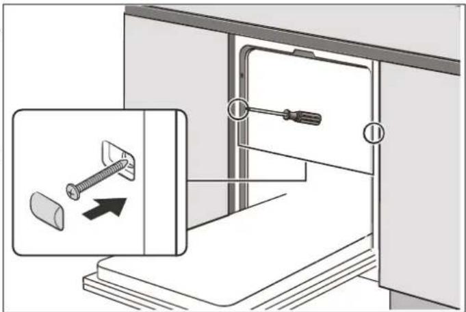
Fig. 22
Fig. 24
INSTALLATÖRENS CHECKLISTA
Fig. 26
| ANTAL | FÖREMÅL |
| 7 Ovalt fat | |
| 8 Litet kokkärl | |
| 9 Desserttallrikar | |
| 10 | Sopptallrikar |
| 11 | Bestickskorg |
| 12 Melaminskålar | |
| 13 | Ugnsgryta |
| 14 Melamindesserttallrikar | |
| 15 | Middagstallrikar |

ANMÄRKNING
natural_image
Black X symbol on a grid of white circular objects, no text or symbols presentFig. 29
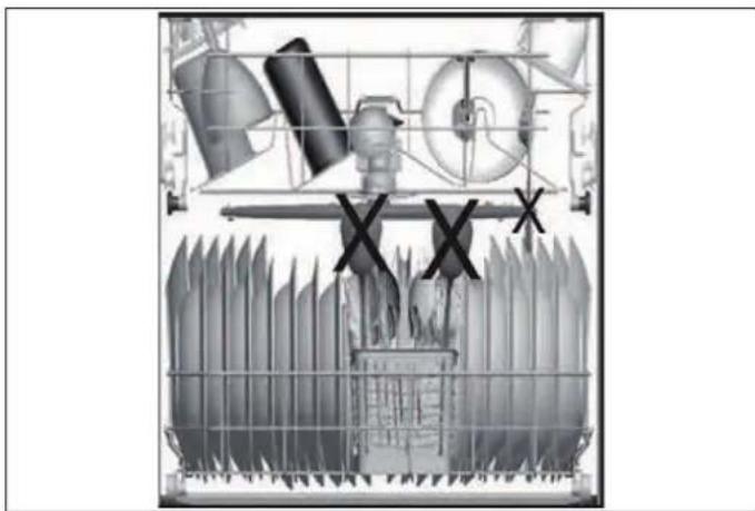
natural_image
Cross-sectional diagram of a mechanical or industrial system with no visible text, numbers, or symbols.Fig. 30
natural_image
Abstract grayscale illustration of mechanical components with a 'X' symbol overlay (no text or symbols present)Fig. 31
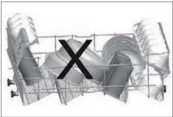
natural_image
3D rendered mechanical component with a black 'X' mark overlay, no visible text or symbolsFig. 32
VAD SKA INTE DISKAS I DIN DISKMASKIN?
ÖVERKORGENS VIKBARA PINNAR OCH HYLLOR
natural_image
3D wireframe model of a structural grid with directional arrows indicating flow or movement (no text or symbols)Fig. 33
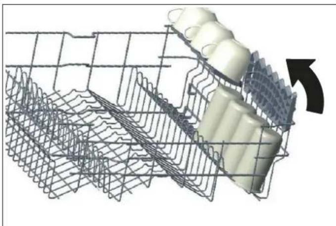
natural_image
3D wire mesh structure with a white cylindrical component inserted, showing internal layered structure (no text or symbols)Fig. 34
natural_image
3D rendering of a red mechanical component with gray structural elements and blue pipes (no text or symbols visible)Fig. 35
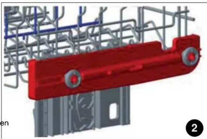
natural_image
3D rendering of a red mechanical component with gray steel framework and blue structural lines (no text or symbols)Fig. 36
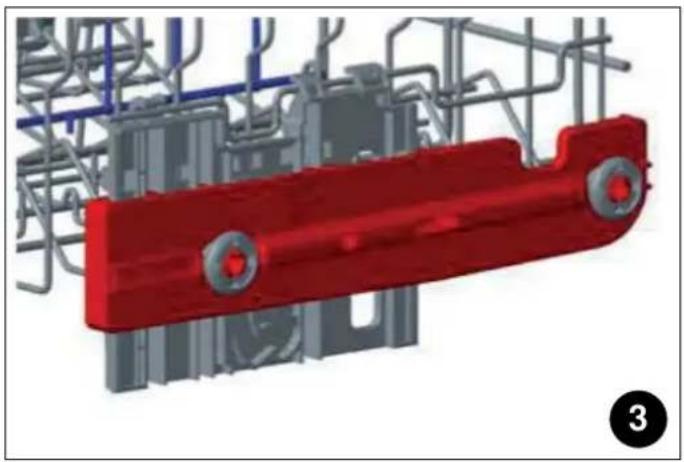
natural_image
3D rendering of a red mechanical component with gray structural elements and blue pipes (no text or symbols visible)Fig. 37
- Dra ut hyllan helt, B.
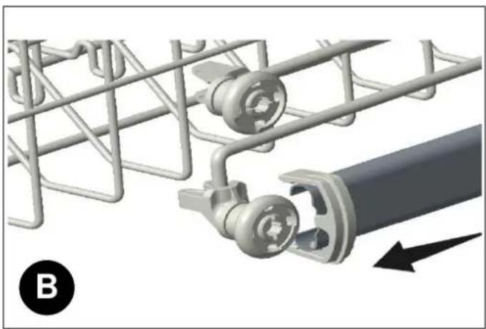
natural_image
Mechanical assembly diagram showing a wire mesh structure and a cylindrical component with a black arrow indicating direction (no text or symbols)Fig. 39
natural_image
Mechanical assembly diagram showing a meshed metal frame with a rotating shaft and directional arrow (no text or symbols)natural_image
Mechanical assembly diagram showing a conveyor belt with rollers and a shaft, no text or symbols presentFig. 40
natural_image
Technical line drawing of a multi-wheeled vehicle chassis with structural supports and wheels (no text or symbols)Fig. 41
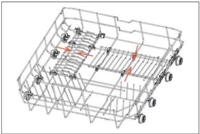
natural_image
Technical line drawing of a multi-wheeled vehicle chassis frame with no visible text or symbolsFig. 42
BESTICKGALLER (BEROENDE PÅ MODELL)
natural_image
3D rendering of a mechanical assembly with no visible text or symbolsFig. 43
natural_image
3D rendering of a mechanical tray with internal grid structure (no text or symbols)Fig. 44
natural_image
3D rendering of a mechanical tray with grid-like internal structure (no text or symbols visible)Fig. 45
natural_image
3D wireframe illustration of a shopping cart with a hand adjusting its interior space, showing no text or symbols.Fig. 47

WARNING
natural_image
3D rendering of a mechanical tray with grid-like internal structure (no text or symbols visible)Fig. 46
FLASKHÅLLARE (BEROENDE PÅ MODELL)
natural_image
3D diagram of a grid-based mechanical or electrical component with purple components and a black arrow indicating direction (no text or symbols)Fig. 48
BRICKHÅLLARE (BEROENDE PÅ MODELL)
natural_image
Technical line drawing of a wheeled agricultural machine (no text or symbols visible)Fig. 49
DIREKTDISKOMRÅDE (BEROENDE PÅ MODELL)
natural_image
Technical line drawing of mechanical components with no visible text or symbolsFig. 51
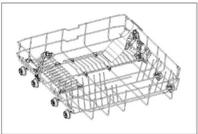
natural_image
Technical line drawing of a wheeled vehicle chassis frame with visible structural components (no text or symbols)Fig. 50
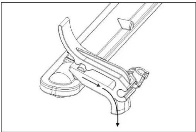
natural_image
Technical line drawing of a mechanical clamp or bracket assembly (no text or symbols)Fig. 52
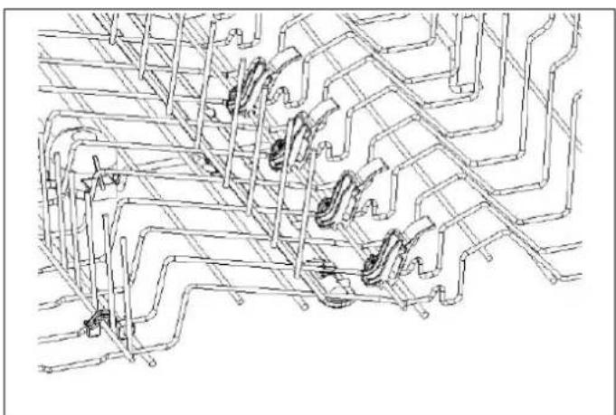
natural_image
Pure technical line drawing of mechanical components without any text, numbers, or symbolsFig. 53
HÅLLARE FÖR GLAS MED FOT (BEROENDE PÅ MODELL)
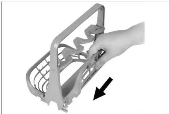
natural_image
Hand holding a metal bracket with a black arrow pointing to it, no visible text or symbols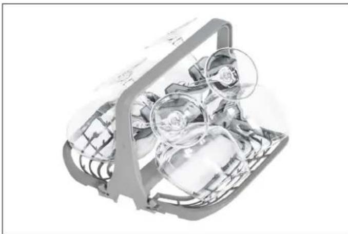
natural_image
Cross-sectional diagram of a mechanical device with internal components and a magnified inset showing internal structure (no text or symbols)Fig. 56
Fig. 54
natural_image
3D rendered image of a transparent plastic device with internal components (no visible text or symbols)Fig. 55
KONTROLLPANEL
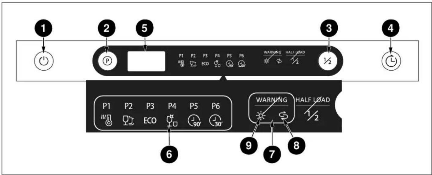
Fig. 57
1) On/Off ("På/Av")-knapp
2) Programknappar
3) Halv diskmängd
4) Delay("Fördröjd") start
5) Display
6) Programindikatorer
7) Varningindikatorer
8) Saltindikator
9) Rinse Aid("Spolglans")-indikator
DRIFT
Fig. 58
ATT FYLLA PÅ SPOLGLANS OCH STÄLLA IN DEN
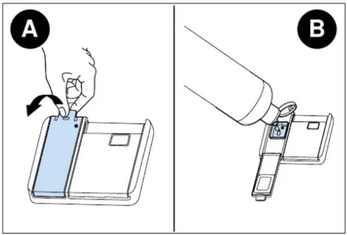
Fig. 59
natural_image
Diagram of a mechanical lever mechanism with an inset showing a close-up of the component (no text or symbols present)Fig. 61
natural_image
Line drawing of a hand using a tool to lift a sink into a basin, with an arrow indicating the process (no text or symbols present)Fig. 62
natural_image
Illustration of hands cleaning a kitchen sink with a tool, no text or symbols presentFig. 63
FILTER
Fig. 64
https://SE.bertazzoni.com/more/care-service
EU ecodesign-wetgeving.
AFMETINGEN UITSPARING
natural_image
Illustration of a hand cleaning a cabinet (no text or symbols)Afb. 11
natural_image
Diagram showing a device being lifted by a curved cable inside a cabinet, with an inset magnified view of the device's motion (no text or symbols present)Afb. 12

OPGELET
natural_image
Architectural diagram showing a roof structure with yellow walls and gray walls (no text or symbols)Afb. 13
PLAATSING VAN DE VAATWASSER IN DE OPENING
Afb. 14
Afb. 15
natural_image
Technical line drawing of a cabinet or enclosure with mounting brackets and internal components (no text or symbols)Afb. 16
natural_image
Technical line drawing of a rectangular frame with two labeled points 'a' and a horizontal bar inside, no text or symbols present.Afb. 17
3.2) Pin de vier lange schroeven (b) vast.
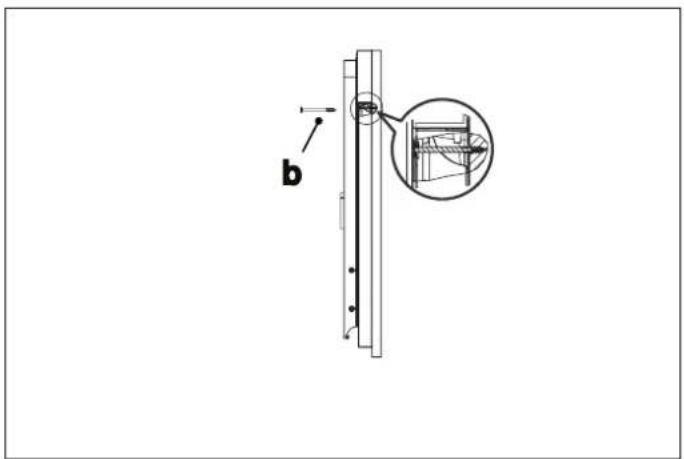
Afb. 18

OPMERKING
natural_image
Technical diagram showing a mechanical assembly with a magnified inset of a gear shift mechanism (no text or labels)Afb. 20
Afb. 21
DE VAATWASSER IN DE KAST BEVESTIGEN
natural_image
Diagram showing a door lock mechanism with screwdriver and plastic clip, no text or symbols presentAfb. 22
natural_image
Illustration of a kitchen appliance with a fan and door, showing airflow direction (no text or symbols)Afb. 24
CHECKLIST INSTALLATEUR
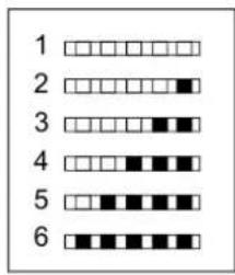
WATERHARDHEID
natural_image
Diagram of a grid with circular objects and a black 'X' symbol overlay (no text or labels)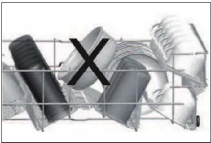
natural_image
Abstract grayscale illustration of mechanical components with a 'X' mark overlay (no text or symbols)Afb. 31
Afb. 29
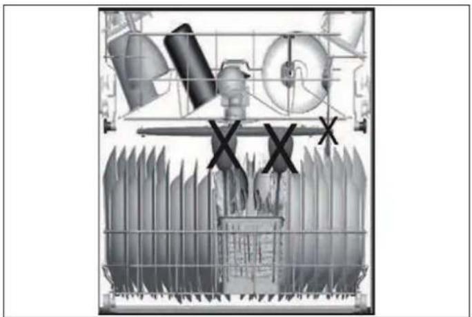
natural_image
Cross-sectional diagram of a mechanical or industrial system with no visible text, numbers, or symbols.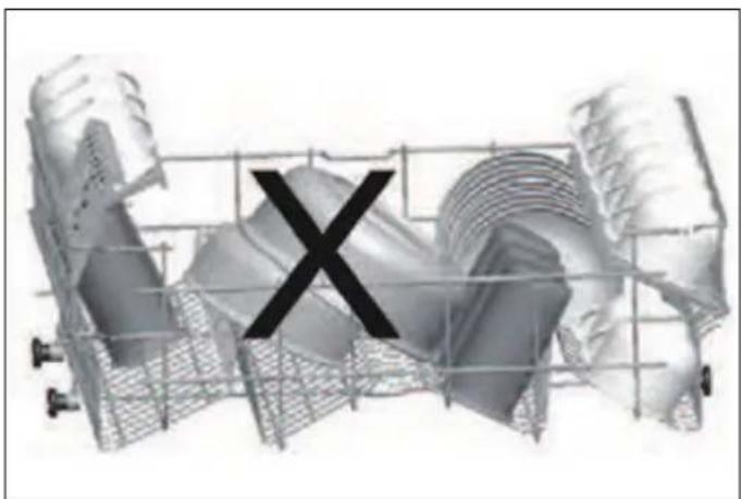
natural_image
3D rendered mechanical components with a black 'X' symbol overlay (no text or labels)Afb. 32
Afb. 30
WAT MAG ER NIET IN DE VAATWASSER WORDEN GEWASSEN?
natural_image
3D wireframe diagram of a structural grid with directional arrows indicating flow or movement (no text or symbols)Afb. 33
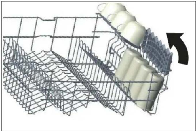
natural_image
3D wire mesh structure with a curved arrow indicating direction (no text or symbols)Afb. 34
natural_image
3D rendering of a red mechanical component with gray structural framework and blue pipes (no text or symbols visible)Afb. 35
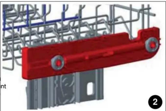
natural_image
3D rendering of a red mechanical component with gray structural elements and blue piping (no text or symbols visible)Afb. 36
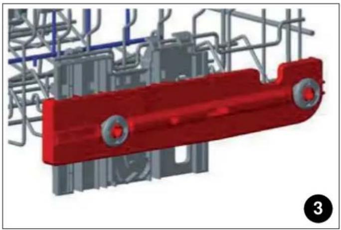
natural_image
3D rendering of a red mechanical component with circular ports, surrounded by steel framework and gray components (no text or symbols visible)Afb. 37
natural_image
Mechanical assembly diagram showing a chain with rollers and a shaft, no text or symbols presentAfb. 39
natural_image
Mechanical assembly diagram showing a meshed metal frame with a rotating shaft and directional arrow (no text or symbols)natural_image
Mechanical assembly diagram showing a shaft and wheel with pipe connections (no text or symbols)Afb. 40
- Druk de grendels terug in de juiste stand.
Afb. 38
OPKLAPBARE TANDEN ONDERSTE MAND
natural_image
Technical line drawing of a multi-wheeled vehicle chassis frame with no visible text or symbolsAfb. 41
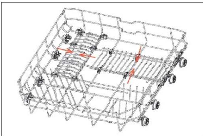
natural_image
Technical line drawing of a multi-wheeled vehicle chassis with visible structural components and red directional arrows indicating motion or movement (no text or symbols)Afb. 42
BESTEKBAK (AFHANKELIJK VAN HET MODEL)
natural_image
Close-up of a mechanical component with no visible text or symbolsAfb. 43
natural_image
3D rendering of a mechanical tray with internal grid structure (no text or symbols)Afb. 44
natural_image
3D rendering of a mechanical tray with internal grid structure (no text or symbols)Afb. 45

WAARSCHUWING
natural_image
3D rendering of a mechanical tray or rack with grid-like internal components (no text or symbols visible)Afb. 46
BESTEKMAND (AFHANKELIJK VAN HET MODEL)
natural_image
3D wireframe diagram of a shopping cart with wheels and a hand holding a tray, showing directional arrows (no text or symbols)Afb. 47
FLESSENHOUDER (AFHANKELIJK VAN HET MODEL)
natural_image
3D diagram of a mechanical assembly with purple components and metal grid lines, no visible text or symbolsAfb. 48
SCHAALHOUDER (AFHANKELIJK VAN HET MODEL)
natural_image
Technical line drawing of a wheeled agricultural machine with no visible text or symbolsAfb. 49
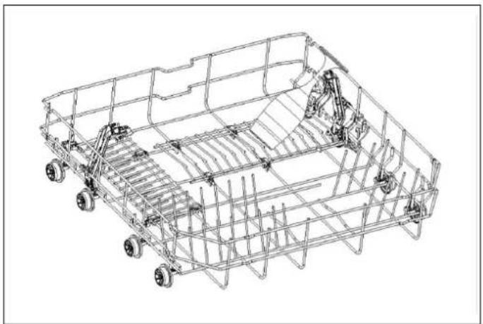
natural_image
Technical line drawing of a wireframe chassis frame with wheels and structural components (no text or symbols)Afb. 50
DIRECTE WASZONE (AFHANKELIJK VAN HET MODEL)
natural_image
Technical line drawing of a mechanical assembly with no visible text or symbolsAfb. 51
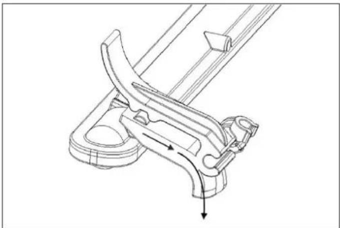
natural_image
Technical line drawing of a mechanical clamp or bracket assembly (no text or symbols)Afb. 52
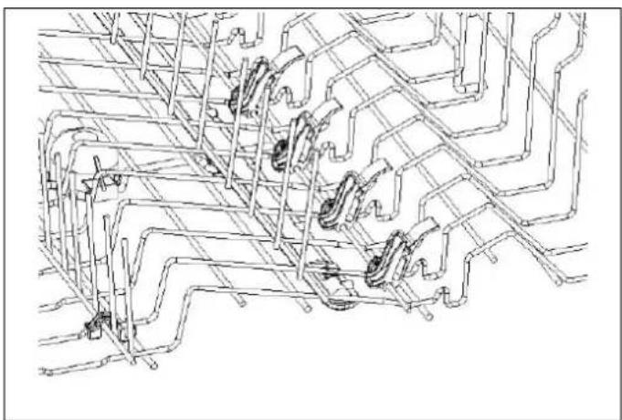
natural_image
Pure technical line drawing of a mechanical assembly without any text, numbers, or symbolsAfb. 53
HOUDER VOOR STEELGLAZEN (AFHANKELIJK VAN HET MODEL)
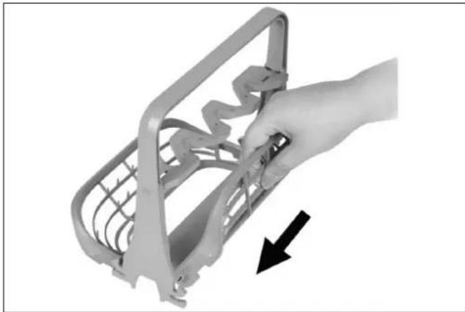
natural_image
Hand holding a metal bracket with a black arrow pointing to the handle (no text or symbols visible)Afb. 54
natural_image
3D rendered mechanical component with transparent casing and internal cavities (no visible text or symbols)Afb. 55
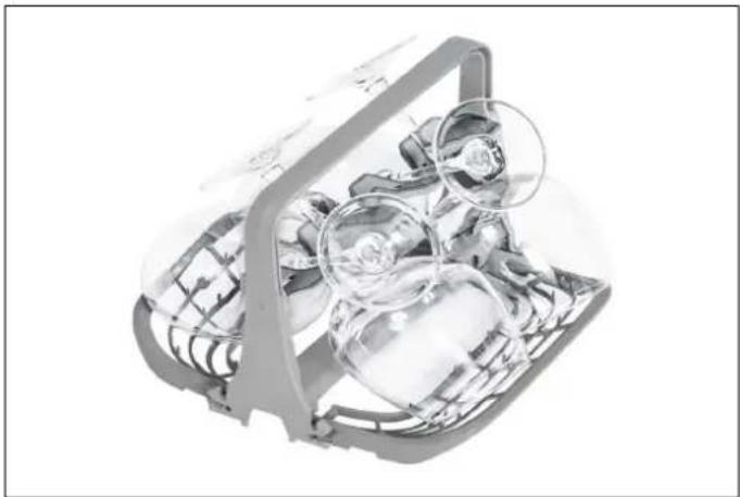
natural_image
Cross-sectional view of a mechanical device with internal components and a magnified inset showing a rose (no text or symbols visible)Afb. 56
OPTIE BESCHRIJVING ACTIVERING
Afb. 58
natural_image
Diagram of a mechanical device with an inset showing a close-up of the component (no text or symbols present)Afb. 61
natural_image
Illustration of a hand using a tool to lift a sink into a basin, with an arrow indicating the process (no text or symbols present)Afb. 62
natural_image
Line drawing of a kitchen sink with hand cleaning the surface and a tool applying powder (no text or symbols)Afb. 63
Afb. 64
INSTALLATIONSMANUAL 276
SPECIFICATIONER 276
GENERELT UDSEENDE 276
TEKNISKE SPECIFIKATIONER 276
INSTALLATION 277
UDSKÆRINGMÅL 277
BRUGERTILPASSET LÅGEPANEL (TIL PANELFORBEREDTE MODELLER) 277
PLACERING AF OPVASKEMASKINEN 278
ELEKTRISKE KRAV 279
VVS-KRAV 280
INSTALLATION 282
BRUGS- OG VEDLIGEHOLDELSESVEJLEDNING 290
BRUG 290
KOM GODT I GANG 290
PLACERING AF TALLERKNER 292
STATIVER 297
BETJENINGSPANEL 303
FUNKTION 304
OPVASKEMIDDEL OG AFSPÆNDINGSMIDDEL 307
SALTDISPENSER (TIL MODELLER MED VANDBL∅DG∅RER) 310
RENG∅RING OG PLEJE 312
SPR∅JTEARME 313
FILTER 314
UDL∅BSPUMPE 314
FEJLFINDING 315
AUTOMATISKE ADVARSLER OM FEJL 317
PRAKTISKE OPLYSNINGER 318
GARANTI OG SERVICE 319
GARANTI OG SERVICE 319
flowchart
graph TD
    A["1: Sawing Tool"] --> B["2: Sliding Tool"]
    B --> C["3: Cracker Clip"]
    C --> D["4: Workpiece"]
    D --> E["5: Scale Gauge"]

    F["6: Pliers"] --> G["7: Screwed Hand"]
    G --> H["8: Screwed Cut"]
    H --> I["9: Screwed Roll"]
    I --> J["10: Brushing Tool"]

    K["11: Glue Tool"] --> L["12: Screwed Clip"]
    L --> M["13: Screwed Cut"]
    M --> N["14: Scissors"]
    N --> O["15: Paintbrush"]
Fig. 10
natural_image
Illustration of a hand cleaning a cabinet (no text or symbols)Fig. 11
natural_image
Illustration of a cabinet interior with a magnified inset showing a device being lifted by a curved cable (no text or symbols)Fig. 12

PAS PÅ
natural_image
Architectural diagram of a modern building corner with yellow walls and gray walls (no text or symbols)Fig. 13
PLACERING AF OPVASKEMASKINEN I ÅBNINGEN
Fig. 14
Fig. 15
natural_image
Technical line drawing of a door frame with internal components and mounting brackets (no text or symbols)Fig. 16
natural_image
Technical line drawing of a rectangular mechanical or architectural component with labeled points 'a' and 'n' (no text or symbols beyond labels)Fig. 17
Fig. 19
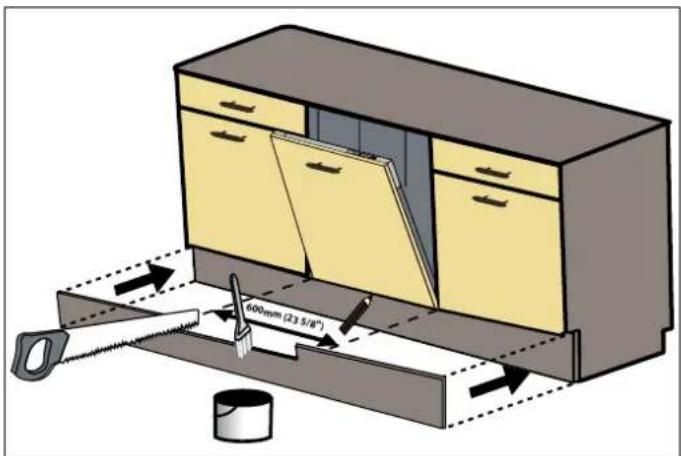
Fig. 21
natural_image
Technical diagram showing a mechanical assembly with an inset close-up of a screwdriver inserted into a component (no text or symbols present)Fig. 20
FASTG∅RELSE AF OPVASKEMASKINEN I SKABET
Fig. 24
TJEKLISTE TIL INSTALLAT∅REN
VANDETS HÅRDHED
natural_image
Diagram of a grid with circular objects and a black 'X' symbol overlay (no text or labels)Fig. 29
natural_image
Abstract grayscale illustration of fragmented 3D geometric shapes with a large 'X' symbol overlay (no text or symbols present)Fig. 31
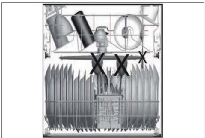
natural_image
Cross-sectional diagram of a mechanical or industrial device with no visible text, numbers, or symbols.Fig. 30
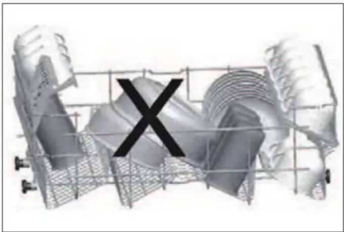
natural_image
3D rendered mechanical component with a black 'X' mark overlay, no visible text or symbolsFig. 32
HVAD B∅R IKKE VASKES I OPVASKEMASKINEN?
natural_image
3D wireframe diagram of a structural grid with directional arrows indicating movement or force (no text or symbols)Fig. 33
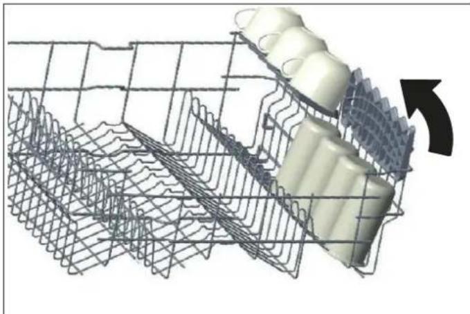
natural_image
3D wire mesh structure with a cylindrical component inserted into a grid, showing internal structure and an arrow indicating rotation (no text or symbols)Fig. 34
natural_image
3D rendered mechanical component with red base and gray internal structure (no visible text or symbols)Fig. 35
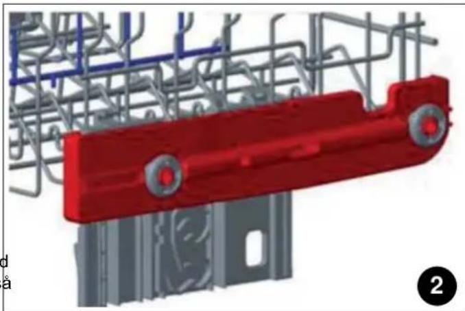
natural_image
3D rendering of a red industrial component with gray steel framework and blue structural lines (no text or symbols visible)Fig. 36
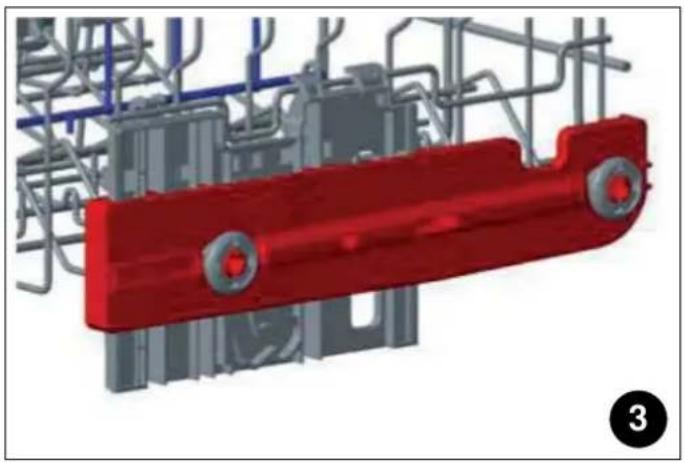
natural_image
3D rendering of a red industrial component with blue pipes and gray structural elements (no text or symbols visible)Fig. 37
natural_image
Mechanical assembly diagram showing a motor and conveyor system with no visible text or symbolsFig. 39
natural_image
Mechanical assembly diagram showing a meshed metal frame with a rotating shaft and directional arrow (no text or symbols)Fig. 38
natural_image
Mechanical assembly diagram showing a conveyor belt with rollers and a shaft, no text or symbols presentFig. 40
- Skub låsene tilbage i den korrekte position.
NEDERSTE KURVS FOLDETÆNDER
natural_image
Technical line drawing of a multi-wheeled vehicle chassis with no visible text or symbolsFig. 41
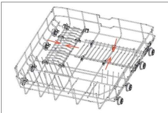
natural_image
Technical line drawing of a vehicle chassis frame with no visible text or symbolsFig. 42
BESTIKBAKKE (AFHÆNGIGT AF MODEL)
natural_image
3D rendering of a mechanical component with internal channels and mounting brackets (no text or symbols visible)Fig. 43
natural_image
3D rendering of a mechanical tray with internal grid structure (no text or symbols)Fig. 44
natural_image
3D rendering of a mechanical tray with grid-like internal structure (no text or symbols visible)Fig. 45
natural_image
3D wireframe diagram of a shopping cart with a hand operating it, showing internal components and directional arrows (no text or symbols)Fig. 47

ADVARSEL
Knive og andre skarpe genstande skal placeres vandret i bestikbakken.
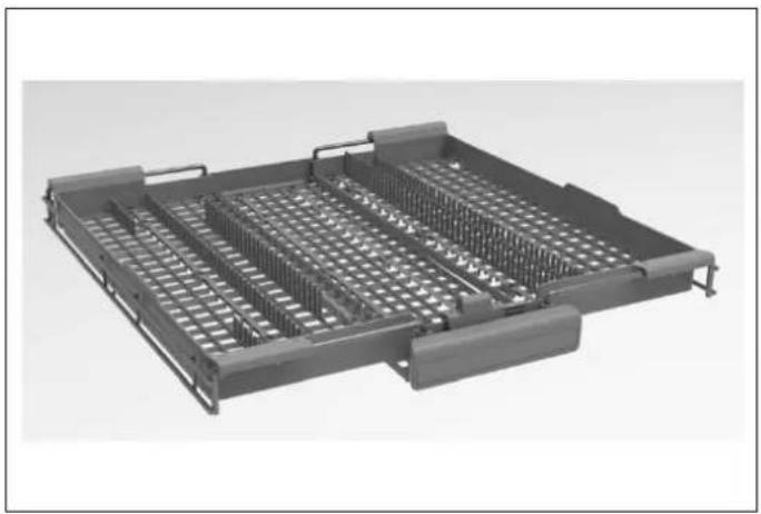
natural_image
Exterior view of a mechanical tray with grid-like internal structure (no text or symbols)Fig. 46
FLASKEHOLDER (AFHÆNGIGT AF MODEL)
natural_image
3D diagram of a grid structure with purple components and black arrows indicating direction (no text or symbols)Fig. 48
BAKKEHOLDER (AFHÆNGIGT AF MODEL)
natural_image
Technical line drawing of a wheeled agricultural machine (no text or symbols visible)Fig. 49
DIREKTE VASKEZONE (AFHÆNGIGT AF MODEL)
natural_image
Technical line drawing of a mechanical assembly with no visible text or symbolsFig. 51
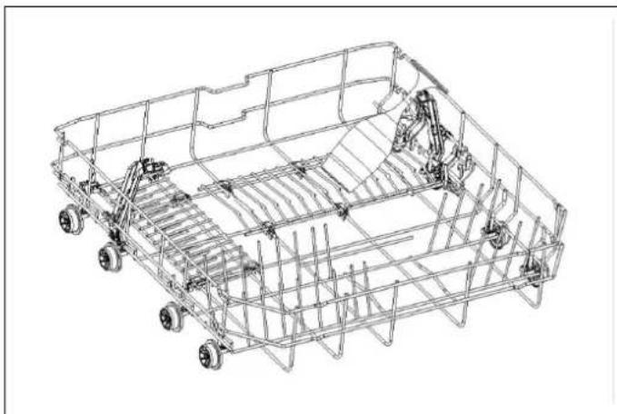
natural_image
Technical line drawing of a wheeled vehicle chassis frame with visible structural components (no text or symbols)Fig. 50
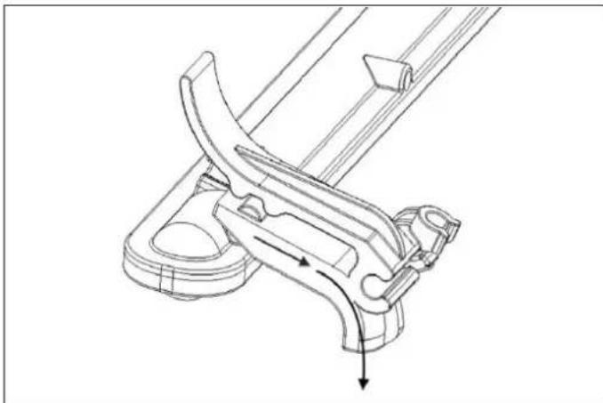
natural_image
Technical line drawing of a mechanical clamp or bracket assembly (no text or symbols)Fig. 52
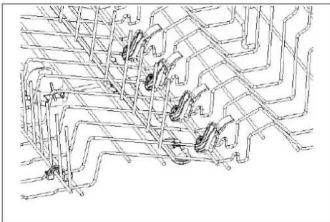
natural_image
Pure technical line drawing of a mechanical assembly without any text, numbers, or symbolsFig. 53
STILKGLASHOLDER (AFHÆNGIGT AF MODEL)
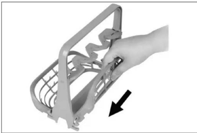
natural_image
Hand holding a metal bracket with a black arrow pointing to the side (no text or symbols visible)Fig. 54
natural_image
Cross-sectional illustration of a mechanical device with internal components (no text or symbols visible)Fig. 55
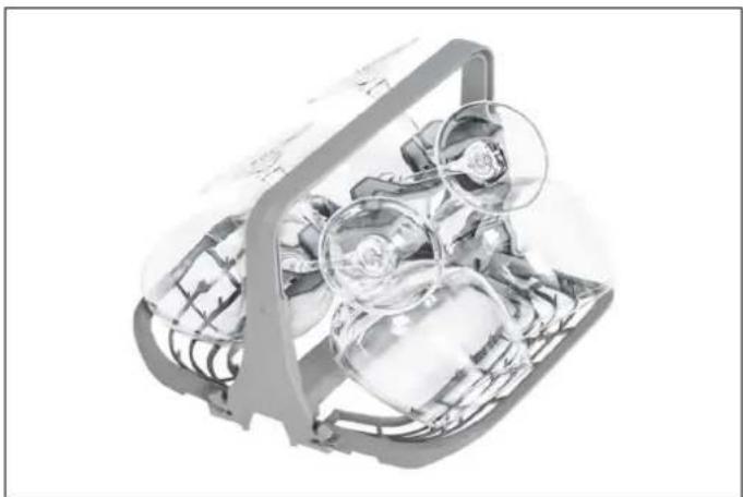
natural_image
Cross-sectional illustration of a mechanical device with internal components and a magnified inset showing a circular detail (no text or symbols)Fig. 56
Fig. 58
natural_image
Technical line drawing of a mechanical lever assembly with an inset showing a close-up of the component (no text or symbols)natural_image
Illustration of hands cleaning a kitchen sink with a tool, showing spray and cleaning process (no text or symbols)Fig. 63
Fig. 61
natural_image
Line drawing of a hand using a tool to lift a sink into a basin, with an arrow indicating the process (no text or symbols present)Fig. 62
FILTER
Fig. 64
a. Mikrofilter
b. Groft filter
c. Metal/plast hovedfilter
https://DK.bertazzoni.com/more/care-service

- FROM THE DESK OF OUR PRESIDENT
- USER MANUAL VALIDITY
- DANGER
- WARNING
- CAUTION
- NOTE
- SAFETY INFORMATION
- RECYCLING
- CE DECLARATION OF CONFORMITY
- DISPOSAL OF YOUR OLD MACHINE
- GENERAL APPEARANCE
- CUTOUT DIMENSIONS
- CUSTOM DOOR PANEL (FOR PANEL-READY MODELS)
- POSITIONING THE DISHWASHER
- ELECTRICAL REQUIREMENTS
- PLUMBING REQUIREMENTS
- INSTALLATION
- TOOLS THAT MAY BE REQUIRED
- MATERIALS THAT MAY BE REQUIRED
- MATERIALS SUPPLIED
- IMPORTANT SAFETY INSTRUCTIONS
- STEAM PROTECTION FOIL
- PLACEMENT OF DISHWASHER INTO THE OPENING
- ADJUSTING THE HEIGHT
- INSTALLING THE OUTER DOOR PANEL (DEPENDING ON MODEL)
- ATTACHING THE KICKPLATE
- INSTALLER CHECKLIST
- FINAL INSTRUCTIONS
- SELF-HELP TIPS
- GETTING STARTED
- PREPARING YOUR DISHWASHER FOR FIRST USE
- SETTING THE WATER SOFTENER
- WATER HARDNESS
- PLATE ARRANGEMENT
- UPPER RACK
- LOWER RACK
- Important Note for Test Laboratories
- THIRD RACK (DEPENDING ON MODEL)
- WHAT SHOULD NOT BE WASHED IN YOUR DISHWASHER?
- RACKS
- UPPER BASKET FOLDING TINES AND ÉTAGÈRES
- 1) Height adjustment with load (depending on model)
- 2) Height adjustment without load (depending on model)
- LOWER BASKET FOLDING TINES
- SILVERWARE TRAY (DEPENDING ON MODEL)
- BOTTLE HOLDER (DEPENDING ON MODEL)
- TRAY HOLDER (DEPENDING ON MODEL)
- DIRECT WASH ZONE (DEPENDING ON MODEL)
- OPERATION
- Setting a wash cycle
- Changing a cycle
- Pausing a cycle
- Switching the dishwasher off
- DETERGENT & RINSE-AID DISPENSER
- FILLING THE DETERGENT
- USING COMBINED DETERGENTS
- RINSE-AID USAGE
- In order to change the rinse-aid level, follow the steps below:
- SALT DISPENSER (FOR MODELS WITH WATER SOFTENER)
- FILLING THE DISHWASHER SALT DISPENSER
- SALT REFILL INDICATOR
- SPRAY ARMS
- FILTER
- DRAIN PUMP
- Warning Risk of cuts
- AUTOMATIC FAULT WARNINGS
- PRACTICAL INFORMATION
- DALLA SCRIVANIA DEL PRESIDENTE
- ATTENZIONE
- NOTA
- LISTA DI CONTROLLO PER L'INSTALLATORE
- DUREZZA DELL'ACQUA
- COSA NON SI DEVE LAVARE IN LAVASTOVIGLIE?
- AVVERTENZA
- iCESTELLO PORTAPOSATE (IN BASE AL MODELLO)
- PORTABOTTIGLIE (A SECONDA DEL MODELLO)
- PORTA VASSOI (A SECONDA DEL MODELLO)
- ZONA DI LAVAGGIO DIRETTO (A SECONDA DEL MODELLO)
- FILTRO
- DÉCLARATION CE DE CONFORMITÉ
- ATTENTION !
- MISE EN PLACE DU LAVE-VAISSELLE DANS LE MEUBLE D'ENCASTREMENT
- ATTACHEMENT DE LA PLAQUE DE PROTECTION
- LISTE DE CONTRÔLE DE L'INSTALLATEUR
- CONSEILS D'AUTO-ASSISTANCE
- DURETÉ DE L'EAU
- QU'EST-CE QUI NE DOIT PAS ÊTRE LAVÉ DANS VOTRE LAVE-VAISSELLE ?
- PLATEAU À COUVERTS (SELON LE MODÈLE)
- MISE EN GARDE
- PANIER À COUVERTS (SELON LE MODÈLE)
- SUPPORT À PLATEAUX (SELON MODÈLE)
- SUPPORT À BOUTEILLES (SELON LE MODÈLE)
- ZONE DE LAVAGE DIRECT (SELON LE MODÈLE)
- SUPPORT DE PORTE-VERRES À PIED (SELON MODÈLE)
- FILTRE
- INFORMATIONS PRATIQUES
- MATERIAL SOM KAN KOMMA ATT BEHÖVAS
- OBSERVERA
- ATT PLACERA DISKMASKINEN I ÖPPNINGEN
- INSTALLATÖRENS CHECKLISTA
- ANMÄRKNING
- VAD SKA INTE DISKAS I DIN DISKMASKIN?
- ÖVERKORGENS VIKBARA PINNAR OCH HYLLOR
- BESTICKGALLER (BEROENDE PÅ MODELL)
- FLASKHÅLLARE (BEROENDE PÅ MODELL)
- BRICKHÅLLARE (BEROENDE PÅ MODELL)
- DIREKTDISKOMRÅDE (BEROENDE PÅ MODELL)
- DRIFT
- AFMETINGEN UITSPARING
- OPGELET
- PLAATSING VAN DE VAATWASSER IN DE OPENING
- OPMERKING
- DE VAATWASSER IN DE KAST BEVESTIGEN
- CHECKLIST INSTALLATEUR
- WATERHARDHEID
- WAT MAG ER NIET IN DE VAATWASSER WORDEN GEWASSEN?
- OPKLAPBARE TANDEN ONDERSTE MAND
- BESTEKBAK (AFHANKELIJK VAN HET MODEL)
- WAARSCHUWING
- BESTEKMAND (AFHANKELIJK VAN HET MODEL)
- FLESSENHOUDER (AFHANKELIJK VAN HET MODEL)
- SCHAALHOUDER (AFHANKELIJK VAN HET MODEL)
- DIRECTE WASZONE (AFHANKELIJK VAN HET MODEL)
- PAS PÅ
- PLACERING AF OPVASKEMASKINEN I ÅBNINGEN
- FASTG∅RELSE AF OPVASKEMASKINEN I SKABET
- TJEKLISTE TIL INSTALLAT∅REN
- VANDETS HÅRDHED
- HVAD B∅R IKKE VASKES I OPVASKEMASKINEN?
- NEDERSTE KURVS FOLDETÆNDER
- BESTIKBAKKE (AFHÆNGIGT AF MODEL)
- ADVARSEL
- FLASKEHOLDER (AFHÆNGIGT AF MODEL)
- BAKKEHOLDER (AFHÆNGIGT AF MODEL)
- DIREKTE VASKEZONE (AFHÆNGIGT AF MODEL)
Brand : BERTAZZONI
Model : DW60S2IEPDV
Category : Dishwasher