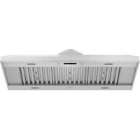
XLH60 - Range hood Thor - Free user manual and instructions
Find the device manual for free XLH60 Thor in PDF.


| Product Type | Kitchen Hood |
| Brand | Thor |
| Model | XLH60 |
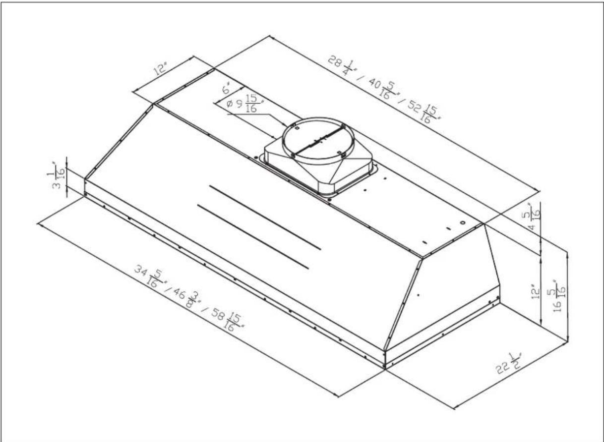
| Dimensions (W x D x H) | 58-15/16 x 22-1/2 x 12 inches |
| Net Weight | 72.1 lb |
| Power Supply | 120 V – 60 Hz, 15 or 20 A |
| Exhaust Duct Diameter | 10 inches (round) |
| Lighting | LED 6 W x 4, two levels (bright/dim/off) |
| Fan Speeds | 6 speeds |
| Gesture Control | Yes (turn on/off, adjust speed) |
| Heat Sensor | Yes (automatic detection, on/off) |
| Filter Type | Baffle Filters (3 for 60 inch model) |
| Filter Maintenance | Clean every 30 days (dishwasher or warm soapy water) |
| Minimum Installation Height | 24 inches above cooking surface |
| Maximum Installation Height | 30 inches for gas range |
| Certification | UL/CSA compliant |
| Warranty | Visit website for details (registration required) |
| Customer Service | (877) 288-8099 |
| Material | Stainless Steel |
Frequently Asked Questions - XLH60 Thor
User questions about XLH60 Thor
0 question about this device. Answer the ones you know or ask your own.
Ask a new question about this device
Download the instructions for your Range hood in PDF format for free! Find your manual XLH60 - Thor and take your electronic device back in hand. On this page are published all the documents necessary for the use of your device. XLH60 by Thor.
USER MANUAL XLH60 Thor
INSTALLATION INSTRUCTIONS
INSTALLATION INSTRUCTIONS
THOR KITCHEN XLH SERIES PROFESSIONATIONAL RANGE HOODS
XLH MODELS
XLH36 | XLH48 | XLH60
TABLE OF CONTENTS
IMPORTANT SAFETY NOTICE 4
1.1 Read and save these instructions .... 4
1.2 Electrical requirements 6
PRODUCT FEATURES / SPECIFICATION CHART....6
2.1 Product Features 6
2.2 Specification Chart....7
2.3 Circuit Diagram....7
2.4 Hood Specifications....8
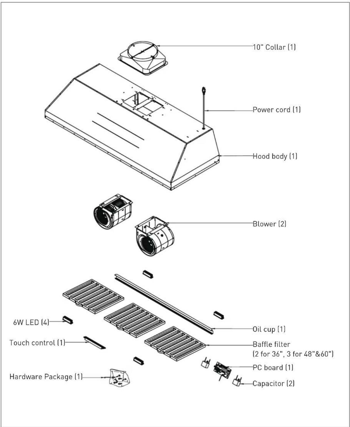
EXPLODED DIAGRAM 9
LIST OF MATERIALS 10
3.1 Parts Supplied....10
INSTALLATION GUIDELINES....10
4.1 Location 10
4.2 Exhaust duct 10
4.3 Position....11
INSTALLATION PROCEDURES 12
BAFFLE FILTER INSTALLATION, REMOVAL AND MAINTENANCE 15
REPLACING LIGHT STRIP 16
WARRANTY 18
1.1 Read and save these instructions
WARNING
To reduce the risk of fire or electric shock, do not use this fan with any solid-state control device.
CAUTION
For General Ventilating Use Only. Do Not Use To Exhaust Hazardous Or Explosive Materials And Vapors.
WARNING
To reduce the risk of fire, electric shock, or injury to persons, observe the following:
a. Use this unit only in the manner intended by the manufacturer. If you have questions, contact the manufacturer.
b. Before servicing or cleaning unit, switch power off at service panel and lock the service disconnecting means to prevent power from being switched on accidentally. When the service disconnecting means cannot be locked, securely fasten a prominent warning device, such as a tag, to the service panel.
WARNING
To reduce the risk of a range top grease fire:
a. Never leave surface units unattended at high settings. Boilovers cause smoking and greasy spillovers that may ignite. Heat oils slowly on low or medium settings.
b. Always turn hood ON when cooking at high heat or when flambeing food (i.e. Crepes Suzette, Cherries Jubilee, Peppercorn Beef Flambe').
c. Clean ventilating fans frequently. Grease should not be allowed to accumulate on fan or filter.
d. Use proper pan size. Always use cookware appropriate for the size of the surface element.
WARNING
To reduce the risk of injury to persons in the event of a range top grease fire, observe the following*:
a. SMOTHER FLAMES with a close-fitting lid, cookie sheet, or metal tray, then turn off the burner. BE CAREFUL TO PREVENT BURNS. If the flames do not go out immediately, EVACUATE AND CALL THE FIRE DEPARTMENT.
b. NEVER PICK UP A FLAMING PAN - You may be burned.
c. DO NOT USE WATER, including wet dishcloths or towels - a violent steam explosion will result.
d. Use an extinguisher ONLY if:
- You know you have a Class ABC extinguisher, and you already know how to operate it.
- The fire is small and contained in the area where it started.
- The fire department is being called.
- You can fight the fire with your back to an exit.
* Based on "Kitchen Firesafety Tips" published by NFPA.
WARNING
To reduce the risk of fire, electric shock, or injury to persons, observe the following:
a. Installation work and electrical wiring must be done by qualified person(s) in accordance with all applicable codes and standards, including fire-rated construction.
b. Sufficient air is needed for proper combustion and exhausting of gases through the flue (chimney) of fuel burning equipment to prevent back drafting. Follow the heating equipment manufacturer's guideline and safety standards such as those published by the National Fire Protection Association (NFPA), and the American Society for Heating, Refrigeration and Air Conditioning Engineers (ASHRAE), and the local code authorities.
c. When cutting or drilling into wall or ceiling, do not damage electrical wiring and other hidden utilities.
d. Ducted fans must always be vented to the outdoors.
e. NEVER place a switch where it can be reached from a tub or shower.
f. Make sure the power is off before installing, wiring or maintaining
WARNING
To reduce the risk of fire, use only metal ductwork.
CAUTION
To reduce risk of fire and to properly exhaust air outside - Do not vent exhaust air into spaces within walls, ceilings, attics, crawl spaces or garages
OPERATION
Always leave safety grilles and filters in place. Without these components, operating blowers could catch onto hair, fingers and loose clothing. The manufacturer declines all responsibility in the event of failure to observe the instructions given here for installation, maintenance and suitable use of the product. The manufacturer further declines all responsibility for injury due to negligence and the warranty of the unit automatically expires due to improper maintenance.
CALIFORNIA PROPOSITION 65 WARNING
WARNING
This appliance contains chemicals known to the State of California to cause cancer and/or reproductive harm, and birth defects or other reproductive harm. For more information go to www.P65Warnings.ca.gov.
IMPORTANT SAFETY NOTICE
1.2 Electrical requirements
Important: Observe all governing codes and ordinances.
It is the customer's responsibility:
- To contact a qualified electrical installer.
- To assure that the electrical installation is adequate and in conformance with National Electrical Code, ANSI/NFPA 70 latest edition* or CSA standards C22.1-94, Canadian Electrical Code, Part 1 and C22.2 No.0-M91 - latest edition** and all local codes and ordinances.
* National Fire Protection Association Batterymarch Park, Quincy, Massachusetts 02269
** CSA International 8501 East Pleasant Valley Road, Cleveland, Ohio 44131-5575
If codes permit and a separate ground wire is used, it is recommended that a qualified electrician determine that the ground path is adequate.
Do not ground to a gas pipe.
Check with a qualified electrician if you are not sure the range hood is properly grounded.
Do not have a fuse in the neutral or ground circuit.
This appliance requires a 120V 60Hz electrical supply and connected to an individual properly grounded branch circuit protected by a 15 or 20 ampere circuit breaker or time delay fuse. Wiring must be 2 wire with ground. Please also refer to Electrical Diagram on product.
A cable locking connector (not supplied) might also be required by local codes.
Check with local requirements, purchase and install appropriate connector if necessary.
PRODUCT FEATURES / SPECIFICATION CHART
2.1 Product Features
- 6-speed options.
- Dual level lighting: Bright, Dim and Off.
- Gesture control function: Turn On and Off, adjust the fan speed.
- Heat sensor: Automatically detect temperature and turn on and off the hood.
PRODUCT FEATURES / SPECIFICATION CHART
2.2 Specification Chart
| Models XLH36 / XLH48 / XLH60 | |
| Net Weight (lbs) 54.5 / 63.6 / 72.1 | |
| Measurement (inches) | (W)34-5/16 × (D)22-1/2 × (H)12 (W)46-3/8 × (D)22-1/2 × (H)12 (W)58-15/16 × (D)22-1/2 × (H)12 |
| Maximum Voltage 120V - 60Hz | |
| Exhaust Pipe Diameter Round 10 inches | |
| Light 6W LED × 4 | |
| Certification |  |
2.3 Circuit Diagram
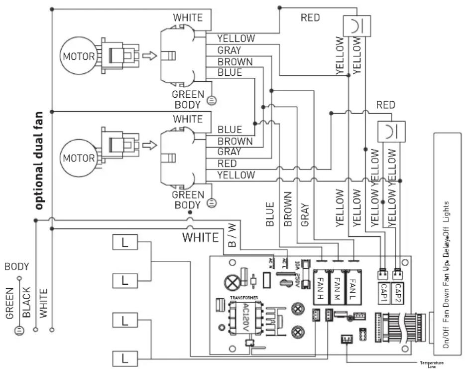
flowchart
graph TD
    subgraph "optional dual fan"
        A["MOTOR"] --> B["WHITE"]
        B --> C["GREEN BODY"]
        C --> D["WHITE"]
        D --> E["BLE"]
        E --> F["BROWN"]
        F --> G["RED"]
        G --> H["YELLOW"]
        H --> I["RED"]
        I --> J["YELLOW YELLOW"]
        J --> K["GREEN BODY"]
        L["BODY"] --> M["L"]
        N["BLACK"] --> O["L"]
        P["WHITE"] --> Q["L"]
        R["BRIDGE"] --> S["TRANSFORMER"]
        T["AC20V"] --> U["TRANSFORMER"]
        V["FANL"] --> W["FANL H"]
        X["CAP1"] --> Y["CAP2"]
        Z["On/Off Fan Down"] --> AA["Temperature Line"]
    end
    style A fill:#f9f,stroke:#333
    style B fill:#ccf,stroke:#333
    style C fill:#cfc,stroke:#333
    style D fill:#fcc,stroke:#333
    style E fill:#cff,stroke:#333
    style F fill:#ffc,stroke:#333
    style G fill:#fcf,stroke:#333
    style H fill:#cff,stroke:#333
    style I fill:#ffc,stroke:#333
    style J fill:#cff,stroke:#333
    style K fill:#ffc,stroke:#333
    style L fill:#cfc,stroke:#333
    style M fill:#fcc,stroke:#333
    style N fill:#cfc,stroke:#333
    style O fill:#fcc,stroke:#333
    style P fill:#cfc,stroke:#333
    style Q fill:#fcc,stroke:#333
    style R fill:#cfc,stroke:#333
    style S fill:#fcc,stroke:#333
    style T fill:#cfc,stroke:#333
    style U fill:#fcc,stroke:#333
    style V fill:#cfc,stroke:#333
    style W fill:#fcc,stroke:#333
    style X fill:#cfc,stroke:#333
    style Y fill:#fcc,stroke:#333
    style Z fill:#cfc,stroke:#333
REMARKS:CONDENSER 11+11uF 250VAC 2PCS FIT AC120V 60Hz
PRODUCT FEATURES / SPECIFICATION CHART
2.4 Hood Specifications
LIST OF MATERIALS
3.1 Parts Supplied
| Standard configuration Hardware packet content | |||||
Hood 1 #8 × 1/2" Flat Head S 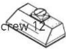 | |||||
Installation guide 1 M4 × 6mm  ping Screw 4 ping Screw 4 | |||||
10" round duct collar 1 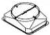 | |||||
Hardware Bracket 1  | |||||
INSTALLATION GUIDELINES
4.1 Location
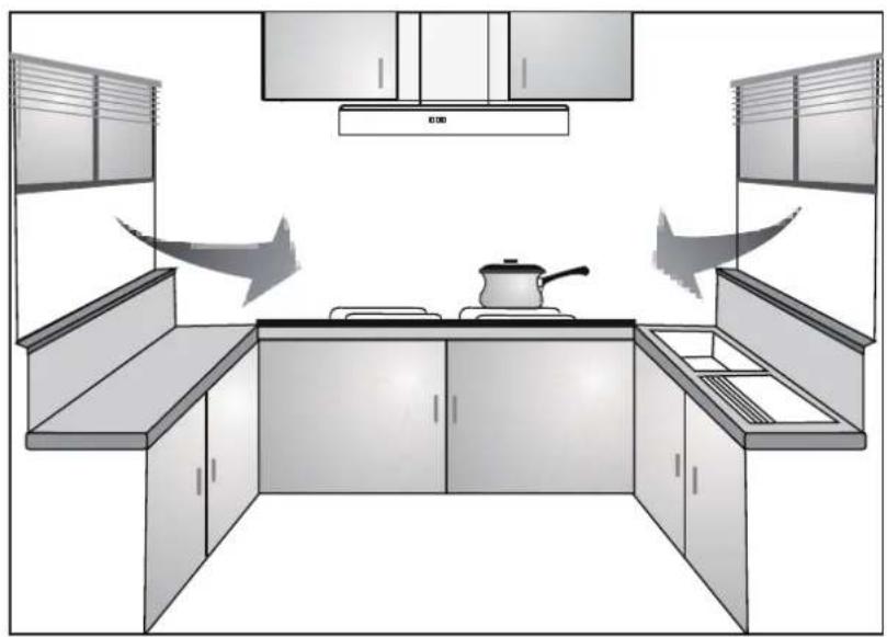
● Air turbulence from window/door may reduce the effectiveness of hood. Suggest to close window/door before using hood. (FIG. 1)
- The smoke has to rise up to 10 inches from cook top in order to reach hood's suction efficiency range.
1
natural_image
Interior view of a modern kitchen with built-in cabinets and a pan on the counter (no text or symbols)4.2 Exhaust duct
- 10" diameter exhaust duct is recommended to use in order to maximize suction efficiency.
- Before installing the hood, please apply fast drying glue to the collar and securely attach it to the top of cooker hood's vent lid. Install the cooker hood and exhaust duct to the plastic collar and seal with fast drying glue.
INSTALLATION GUIDELINES
4.3 Position
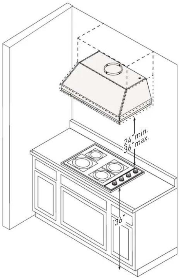
- The installation height is measured vertically from center of aluminum filter of hood to the top of the cook top.
● The min height is 24 inches and the max installation height is 36 inches for gas hob. (FIG. 2) - Avoid left-right or front-dropped inclination.
2
INSTALLATION PROCEDURES

CAUTION
At least two installers are required due to the weight and size of the hood.
-
Remove all packing materials and protective film prior to installation. Use caution during installation to prevent scratches or damage to the stainless steel.
-
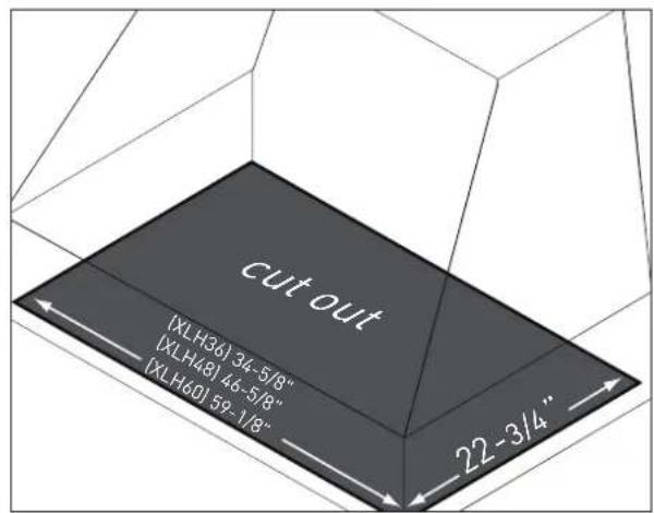
Cut out an opening in the bottom of the cabinet by following the dimensions in.
3
-
Remove baffle filters by following the steps on page 11.
-
Remove oil cup by: ① Pulling up on cup to release from bottom panel. ② Lifting cup out of liner body.
4

WARNING
Make sure the surface you are securing the liner to is capable of holding the weight of XLH. Failure to do so may cause personal injury or damage to cooking surface or counter.
- Remove left and right side panels by removing (2) screws from behind each panel.
5

natural_image
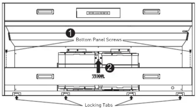
Architectural line drawing of a building facade with structural elements and doorways (no text or symbols)- Remove bottom panel by: ① Removing (2) screws from left and right sides of bottom panel. ② Pulling bottom panel toward front of liner to release from locking tabs.
6
INSTALLATION PROCEDURES
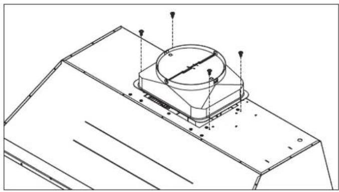
- Secure 10" round ducting collar to top of insert by (4) M4 × 6mm screws.
7
natural_image
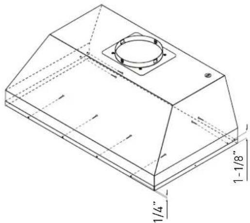
Technical line drawing of a mechanical component with mounting flanges and a central circular feature (no text or symbols)- Lift hood into bottom opening of cabinet and secure to interior of cabinet using #8 × 1/2" stainless steel screws; For 36" & 48": there are (4) screws in the front and (4) screws in the sides. For 60": there are (6) screws in the front and (4) screws in the sides.
8
natural_image
Technical line drawing of a 3D mechanical component with dimension annotations (1/4" and 1-1/8")- Finalize installation of electrical and duct work. Seal duct work with certified aluminum duct tape. Power on hood, check for leaks around duct tape and verify proper operation.
NOTICE If access to top of hood is not available after installation, electrical and duct work connection may need to be made prior to installing the liner.
- Re-install the previously removed bottom panel, side panels (if applicable), oil cup, and baffle filters.
BAFFLE FILTER INSTALLATION, REMOVAL AND MAINTENANCE
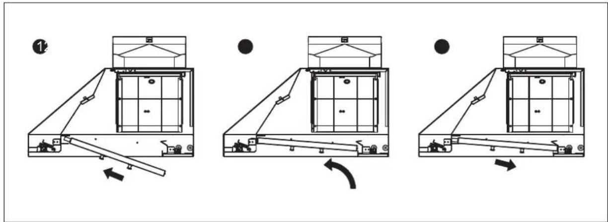
Installing the Baffle Filters
- Place filter into top groove of the liner as shown and pull towards front of liner using handles.
- Pivot back of filter upwards so it is angled in the liner.
- Push filter into channel on back of liner to lock into place.
Removing the Baffle Filters
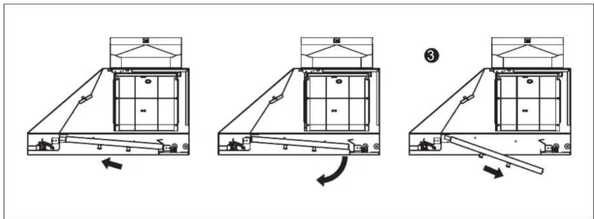
- Pulling filter toward front of liner.
- Pivoting rear of filter down.
- Pull filter out of the channel on front of liner to remove.
Cleaning the Baffle Filters
The filters are intended to trap residue and grease from cooking. Although the filters should never need replacing, they are required to be cleaned every 30 days or more often depending on cooking habits.
Filters may be placed in dishwasher at low heat or soaked in hot soapy water Dry filters and re-install before using hood.
REPLACING LIGHT STRIP
LED Light:
For LED light strip replacement or service, please contact Thor Kitchen customer service or parts department.
WARNING
Improper installation, service, or maintenance may cause injury or damage. Refer to this manual for detailed instructions. All other service should be performed by an authorized service provider.
Failure to follow these instructions can result in serious injury, fire, or electrical shock.
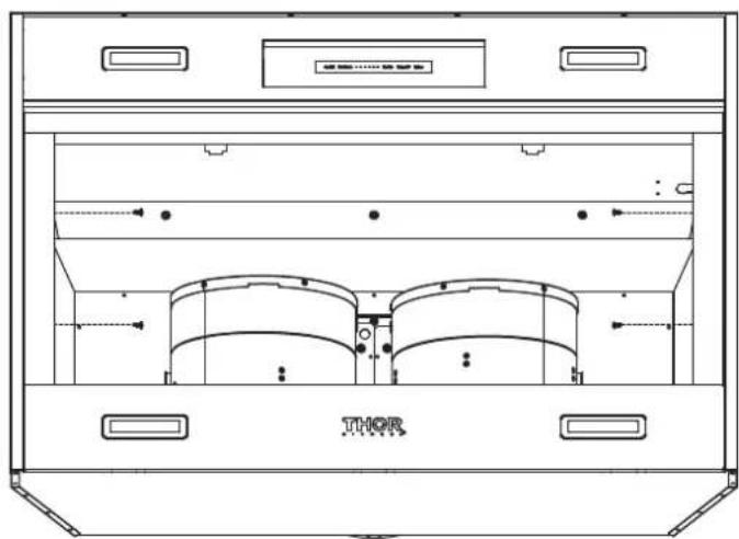
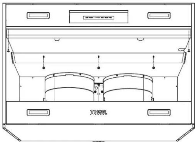
- After turning off the power, remove baffle filters.
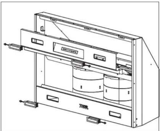
- Remove two screws on both sides and remove the side panel. (for 36" & 60")
natural_image
Technical line drawing of a Thermostor cabinet with ventilation ducts and control buttons (no text labels or symbols)- Remove light panel by five screws.
natural_image
Technical line drawing of a Therium (THOR) device casing with internal compartments and mounting brackets (no text or symbols)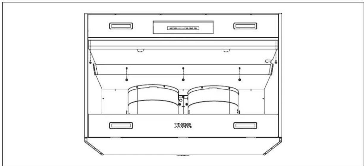
natural_image
Technical line drawing of a Thermostor device casing with internal compartments and mounting points (no text or symbols)REPLACING LIGHT STRIP
- Press the light panel and pull it forward to remove the lighting panel.
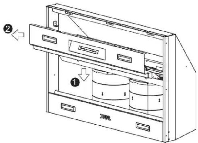
- Disconnect LED light quick connector.
- Push the clips on each side of the LED light strips simultaneously and take off the light strip.
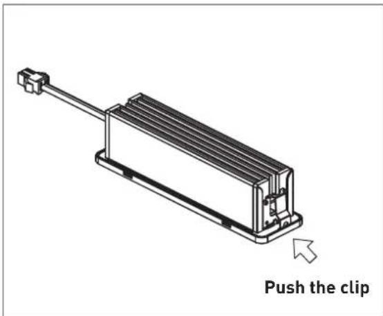
natural_image
Technical line drawing of a mechanical device with internal components and mounting brackets (no text or symbols)THOR K I T C H E N®
Warranty&Service
This product has been manufactured by Thor International, 4651 E Airport Drive, California 91761
For Customer Service, please call (877) 288 - 8099
For the most up to date warranty and service policy, please refer to our website WWW.THORKITCHEN.COM/WARRANTY-REGISTRATION
For in-warranty service requests, please visit our website at WWW.THORKITCHEN.COM/SERVICE
Please Note: You must provide proof of purchase or installation date for any in-warranty service requests
TABLE DES MATIÈRES
REMARQUE IMPORTANTE CONCERNANT LA SÉCURITÉ....20
natural_image
Interior view of a modern kitchen with built-in cabinets and a pot on the counter (no text or symbols)▲ AVERTISSEMENT
natural_image
Architectural line drawing showing structural components and elevation markers (no text or symbols)natural_image
Technical line drawing of a mechanical component with mounting flanges and a central circular feature (no text or symbols)natural_image
Technical line drawing of a 3D mechanical component with dimension annotations (no readable text or symbols)natural_image
Technical line drawing of a Theror device casing with ventilation ducts and control buttons (no text or symbols)natural_image
Technical line drawing of a Thermostat enclosure with ventilation ducts and doorways (no text or symbols)REPLACEMENT DE LA BANDE LUMINEUSE
natural_image
Technical line drawing of a mechanical device with internal components and mounting brackets (no text or symbols)THOR KITCHEN®
Garantie et service
natural_image
Interior view of a modern kitchen with built-in cabinets and a pan on the counter (no text or symbols)4.2 Ducto de escape
ADVERTENCIA
natural_image
Technical line drawing of a mechanical assembly with no visible text or symbolsnatural_image
Technical line drawing of a mechanical component with mounting flanges and a central circular feature (no text or symbols)natural_image
Technical line drawing of a 3D mechanical component with dimension annotations (no readable text or symbols)natural_image
Technical line drawing of a mechanical assembly with no visible text or symbols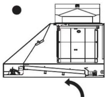
natural_image
Technical line drawing of a mechanical assembly with no visible text or symbols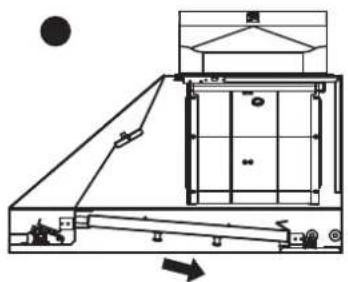
natural_image
Technical line drawing of a mechanical assembly with no visible text or symbolsnatural_image
Technical line drawing of a mechanical device with no visible text or symbols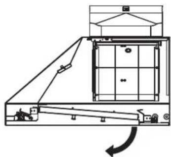
natural_image
Technical line drawing of a mechanical device with no visible text or symbols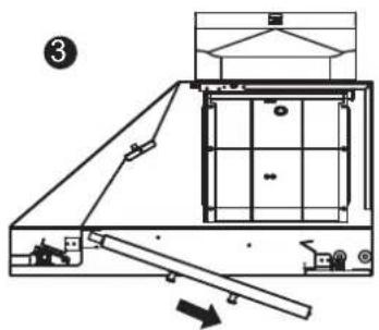
natural_image
Technical line drawing of a Thermostor cabinet with ventilation ducts and control buttons (no text or symbols)natural_image
Technical line drawing of a Thermostor device casing with internal compartments and mounting brackets (no text or symbols)REEMPLAZO DE LA CINTA DE LUCES
natural_image
Technical line drawing of a mechanical device with internal components and mounting brackets (no text or symbols)THOR KITCHEN®
Garantía y servicio
You chose THOR Kitchen to enhance your culinary journey and we're stoked to have you in the club. Think of it as a secret society of really savvy people, such as yourself, choosing professional power and performance at an affordable price.

Register your product by following the steps below.
WARRANTY REGISTRATION

Scan the QR code or visit thorkitchen.com/warranty
Input your product info and select register

You're done. Let's get cookin'.
WARRANTY NEED PARTS?


- INSTALLATION INSTRUCTIONS
- THOR KITCHEN XLH SERIES PROFESSIONATIONAL RANGE HOODS
- TABLE OF CONTENTS
- IMPORTANT SAFETY NOTICE 4
- PRODUCT FEATURES / SPECIFICATION CHART....6
- EXPLODED DIAGRAM 9
- LIST OF MATERIALS 10
- INSTALLATION GUIDELINES....10
- INSTALLATION PROCEDURES 12
- BAFFLE FILTER INSTALLATION, REMOVAL AND MAINTENANCE 15
- REPLACING LIGHT STRIP 16
- WARRANTY 18
- Read and save these instructions
- WARNING
- CAUTION
- OPERATION
- IMPORTANT SAFETY NOTICE
- Electrical requirements
- PRODUCT FEATURES / SPECIFICATION CHART
- Product Features
- Circuit Diagram
- Hood Specifications
- LIST OF MATERIALS
- Parts Supplied
- INSTALLATION GUIDELINES
- Location
- Exhaust duct
- Position
- INSTALLATION PROCEDURES
- At least two installers are required due to the weight and size of the hood.
- BAFFLE FILTER INSTALLATION, REMOVAL AND MAINTENANCE
- Installing the Baffle Filters
- Removing the Baffle Filters
- Cleaning the Baffle Filters
- REPLACING LIGHT STRIP
- LED Light:
- THOR K I T C H E N®
- Warranty&Service
- TABLE DES MATIÈRES
- REMARQUE IMPORTANTE CONCERNANT LA SÉCURITÉ....20
- ▲ AVERTISSEMENT
- REPLACEMENT DE LA BANDE LUMINEUSE
- THOR KITCHEN®
- Garantie et service
- Ducto de escape
- ADVERTENCIA
- REEMPLAZO DE LA CINTA DE LUCES
- Garantía y servicio
- WARRANTY REGISTRATION
Brand : Thor
Model : XLH60
Category : Range hood