LFG818W - Basket ELECTROLUX - Free user manual and instructions
Find the device manual for free LFG818W ELECTROLUX in PDF.

| Product type | Wall-mounted range hood |
| Brand | Electrolux |
| Model | LFG818W |
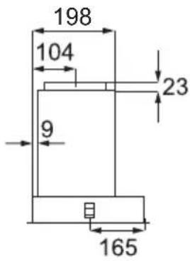
| Width | 80 cm |
| Depth | 50 cm |
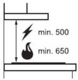
| Minimum height | 65 cm above the cooking surface |
| Weight | Approximately 15 kg |
| Power supply | 220-240 V, 50 Hz |
| Connection power | 200 W (estimated) |
| Extraction type | Recirculation or external extraction |
| Number of speeds | 3 speeds |
| Lighting | Integrated LED |
| Grease filters | Washable metal filters |
| Filter cleaning frequency | Every 2 months |
| Filter saturation indicator | No |
| Automatic shut-off function | Not specified |
| Remote control | No |
| Noise level | Approximately 55 dB (estimated) |
| Energy efficiency class | B (estimated) |
| Child safety | Not specified |
| Material | Stainless steel and glass |
| Color | White |
| Warranty | 2 years (standard) |
Frequently Asked Questions - LFG818W ELECTROLUX
User questions about LFG818W ELECTROLUX
0 question about this device. Answer the ones you know or ask your own.
Ask a new question about this device
Download the instructions for your Basket in PDF format for free! Find your manual LFG818W - ELECTROLUX and take your electronic device back in hand. On this page are published all the documents necessary for the use of your device. LFG818W by ELECTROLUX.
USER MANUAL LFG818W ELECTROLUX
EN Safety Information and Installation Instruction 29
BG
Before the installation and use of the appliance, carefully read the supplied instructions. The manufacturer is not responsible for any injuries or damage that are the result of incorrect installation or usage. Always keep the instructions in a safe and accessible location for future reference.
1.1 Children and vulnerable people safety
- This appliance can be used by children aged from 8 years and above and persons with reduced physical, sensory or mental capabilities or lack of experience and knowledge if they have been given supervision or instruction concerning the use of the appliance in a safe way and understand the hazards involved. Children of less than 8 years of age and persons with very extensive and complex disabilities shall be kept away from the appliance unless continuously supervised.
- Children should be supervised to ensure that they do not play with the appliance.
- Keep all packaging away from children and dispose of it appropriately.
- Keep children and pets away from the appliance when it operates.
- Children shall not carry out cleaning and user maintenance of the appliance without supervision.
1.2 General Safety
- This appliance is intended for domestic use above hobs, cookers and similar cooking devices.
- This appliance is designed for single household domestic use in an indoor environment.
-
This appliance may be used in offices, hotel guest rooms, bed & breakfast guest rooms, farm guest houses and other similar accommodation where such use does not exceed (average) domestic usage levels.
-
Before carrying out any maintenance, disconnect the appliance from the power supply.
- CAUTION: Accessible parts may become hot during use with cooking appliances.
- Use only the fixing screws supplied with the appliance if not supplied, use the screws recommended in the installation instructions. Install the appliance in a safe and suitable place that meets installation requirements.
- WARNING: Failure to install the screws or fixing device in accordance with these instructions may result in electrical hazards.
- Do not use adhesives to fix the appliance.
- The minimum distance between the hob surface on which the pans stand and the lower part of the appliance shall be at least 65 cm, unless otherwise specified in the installation instructions for the appliance or hob.
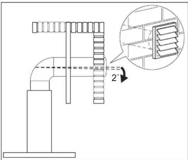
- The discharge of air must comply with local authorities regulations.
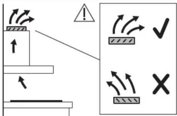
- Ensure good air ventilation in the room where the appliance is installed to avoid the backflow of gases into the room from appliances burning gas or other fuels, including open fires.
- Make sure that the ventilation openings are not blocked and the air collected by the appliance is not conveyed into a duct used to exhaust smoke and steam from other appliances (central heating systems, thermosiphons, water-heaters, etc.).
- When the appliance operates with other appliances the maximum vacuum generated in the room should not exceed 0.04 mbar.
- If the supply cord is damaged, it must be replaced by the manufacturer, its Authorised Service Centre or similarly qualified persons to avoid an electrical hazard.
-
If the cord set is damaged, it must be replaced by a special cord set available from the manufacturer or its Authorised Service Centre.
-
If the appliance is connected directly to the power supply, the electrical installation must be equipped with an isolating device that allows to disconnect the appliance from the mains at all poles. Complete disconnection must comply with conditions specified in the overvoltage category III. The means for disconnection must be incorporated in the fixed wiring in accordance with the wiring rules.
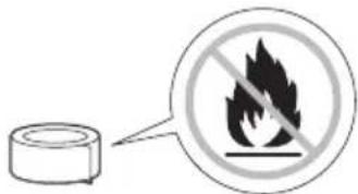
- Do not flambé under the appliance.
- Do not use to exhaust hazardous or explosive materials and vapours.
- Clean the appliance regularly with a soft cloth to prevent the deterioration of the surface material.
- Do not use a steam cleaner, water spray, harsh abrasive cleaners or sharp metal scrapers to clean the surface of the appliance. Use only neutral detergents.
- Clean grease filters regularly (at least every 2 months) and remove grease deposits from the appliance to prevent the risk of fire.
- Use a cloth to clean the interior of the appliance.
2. SAFETY INSTRUCTIONS
2.1 Installation

WARNING!
Risk of injury, electric shock, fire, burns or damage to the appliance.
- Only a qualified person must install this appliance.
- Do not install or use a damaged appliance.
- Follow the installation instructions supplied with the appliance.
• Always take care when moving the appliance as it is heavy. Always use safety gloves and enclosed footwear. - Before installing the appliance remove all the packaging, the labelling and the protective film.
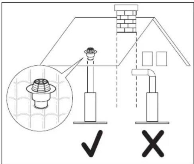
- Do not install the exhaust air into a wall cavity, unless the cavity is designed for that purpose.
2.2 Electrical connection

WARNING!
Risk of fire and electric shock.
- All electrical connections should be made by a qualified electrician.
- Make sure that the parameters on the rating plate are compatible with the electrical ratings of the mains power supply.
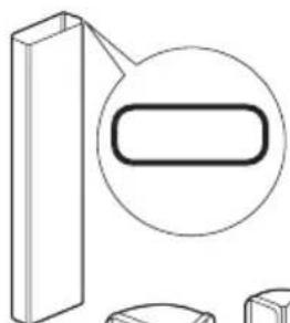
- If the symbol (☐) is not printed on the rating plate, the appliance must be earthed.
• Always use a correctly installed shockproof socket. - Do not let the electricity mains cable tangle.
- Do not use multi-plug adapters and extension cables.
-
If the mains socket is loose, do not connect the mains plug.
-
Do not pull the mains cable to disconnect the appliance. Always pull the mains plug.
- The shock protection of live and insulated parts must be fastened in such a way that it cannot be removed without tools.
- Make sure the appliance is installed correctly. Loose and incorrect electricity mains cable can make the terminal become too hot.
- Connect the appliance at the end of the installation. Make sure that there is access to the mains after the installation.
2.3 Use

WARNING!
Risk of injury, burns and electric shock.
- This appliance is for cooking purpose only. Do not use the appliance for any other purpose.
- Do not change the specification of this appliance.
- Do not operate the appliance with wet hands or when it has contact with water.
- Use only the accessories supplied with the appliance.
- Keep flames or heated objects away from fats and oils during cooking and frying.
- Do not use uncovered electric grills.
- Do not use the appliance as a storage surface.
- Do not pour liquids over the appliance.
- Do not use magnifying glasses, binoculars or similar optical devices to look directly at the lighting of the appliance.
- If the appliance works with other devices, the maximum developed pressure must not exceed 4 Pa (4x10⁻⁵ bar).
2.4 Service
• To repair the appliance contact the Authorised Service Centre. Use original spare parts only.
- Concerning the lamp(s) inside this product and spare part lamps sold separately: These lamps are intended to withstand extreme physical conditions in household appliances, such as temperature, vibration, humidity, or are intended to signal information about the operational status of the appliance. They are not intended to be used in other applications
and are not suitable for household room illumination.
2.5 Disposal

WARNING!
Risk of injury or suffocation.
- Contact your municipal authority for information on how to dispose of the appliance.
- Disconnect the appliance from the mains supply.
- Cut off the mains electrical cable close to the appliance and dispose of it.
ES
1. ⚠TURVALLISUUSTIEDOT
ELECTROLUX APPLIANCES AB
BUSINESS SECTOR EMA-EMEA (SEE)
ST GÖRANSGATAN 143
SE-105 45 STOCKHOLM
SWEDEN
TEL: +46 (8) 738 60 00
FAX: +46 (8) 738 63 35
www.electrolux.com


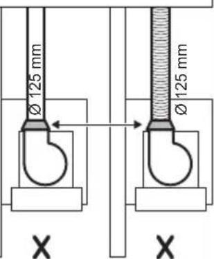


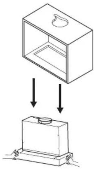
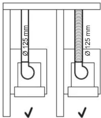
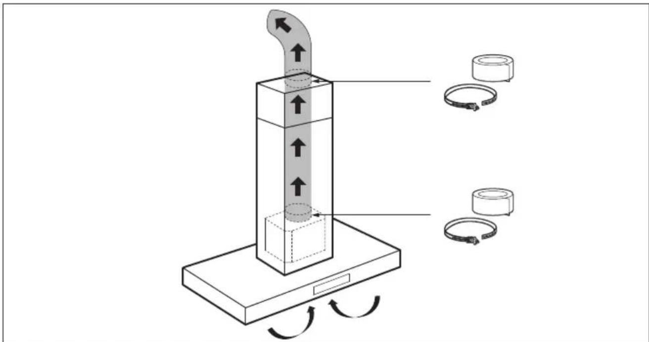
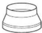
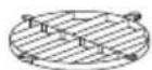
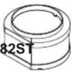
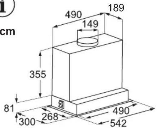
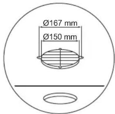
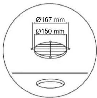
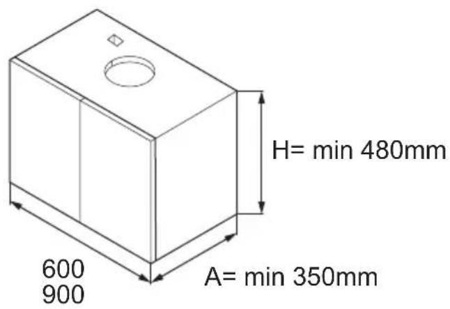
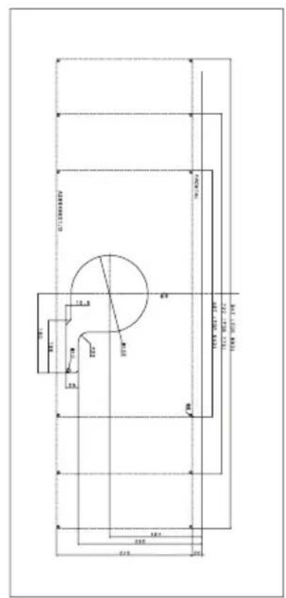
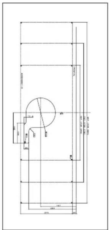
Motor outlet
diameter 120 mm


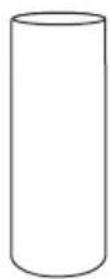
natural_image
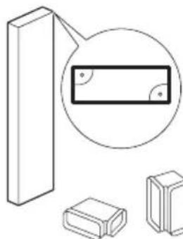
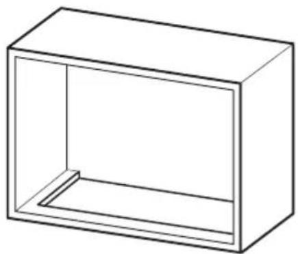
Pure technical diagram of a rectangular block with an oval highlight, no text or symbols present


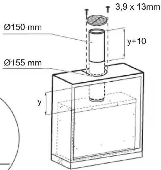
natural_image
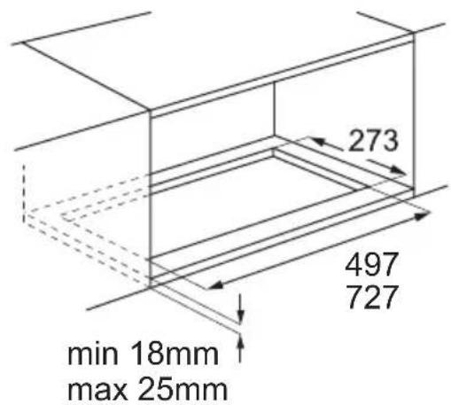
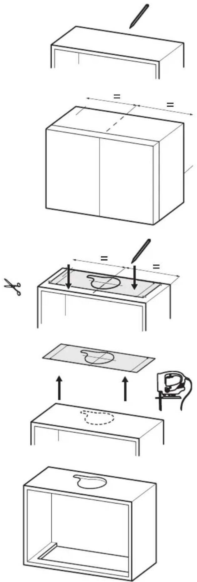
Technical illustration of a rectangular block with an inset close-up showing a rectangle and two smaller blocks (no text or symbols)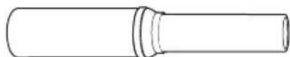
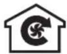
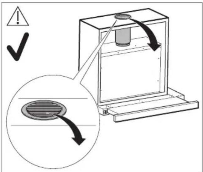
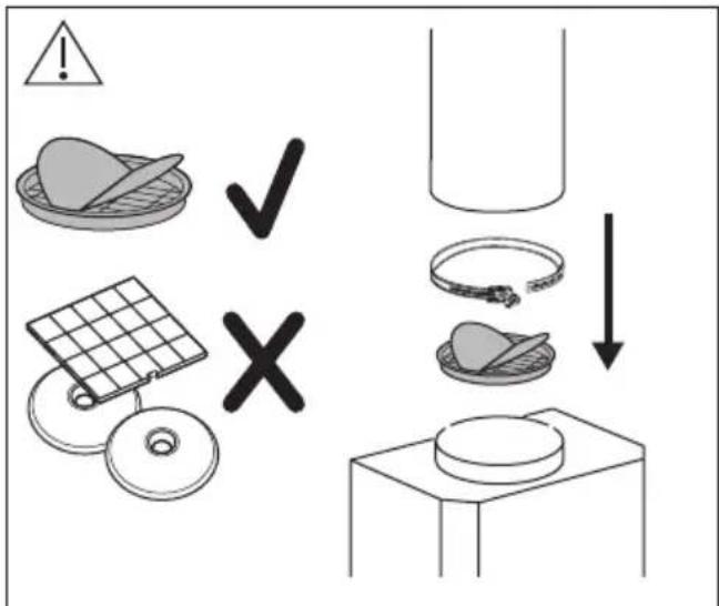
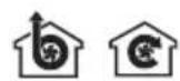
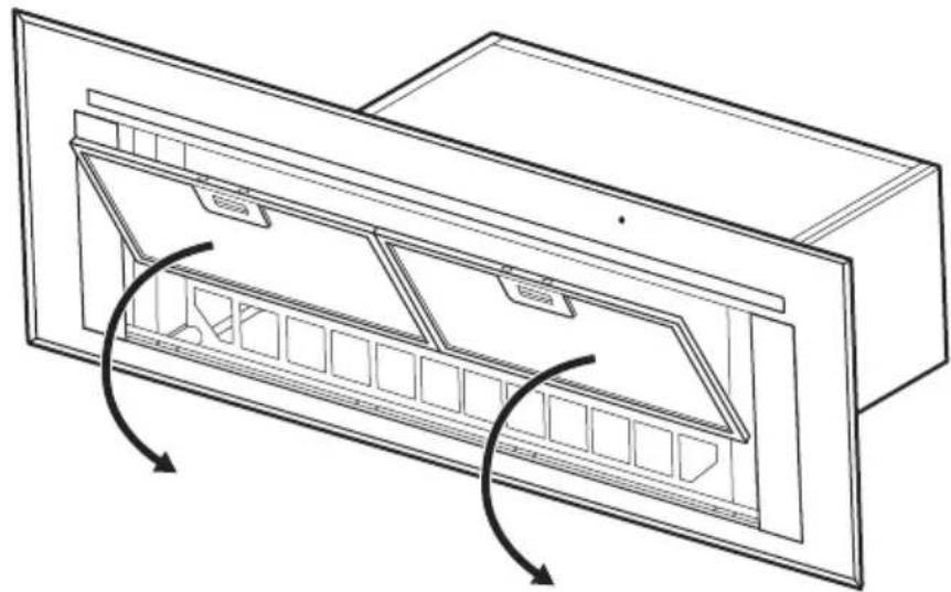
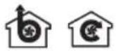
RECIRCULATION MODE
natural_image
Diagram of a mechanical device with rotating components and directional arrows indicating motion (no text or symbols)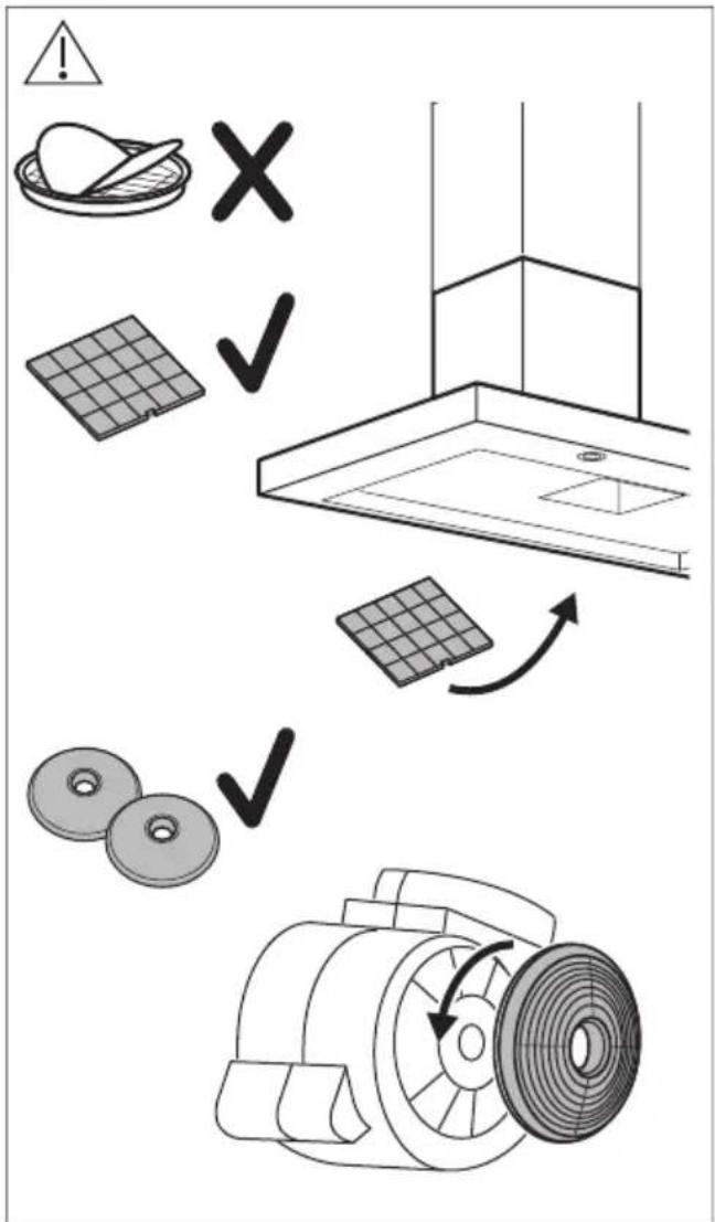
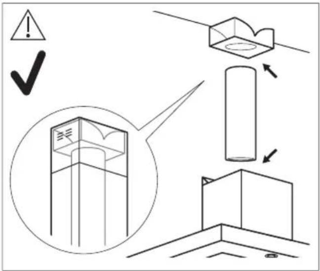
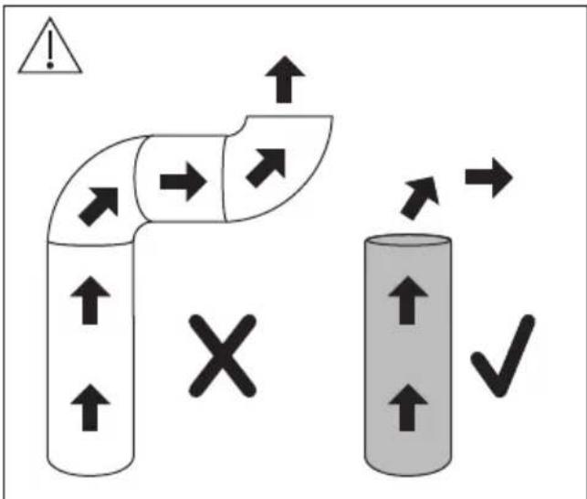
EXTRACTION MODE

natural_image
Silhouette of a human figure in black silhouette (no text or symbols)
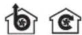
natural_image
Icon of two gloves inside a circle (no text or symbols)
natural_image
Simple line drawing of a boot inside a circle (no text or symbols)
YouTube
www.youtube.com/electrolux
www.youtube.com/aeg
How to install your Myron hood


natural_image
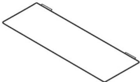
Simple line drawing of a rectangular frame with corner edges (no text or symbols)x1
x1
x1

x2
x1
140cm
x1
x1


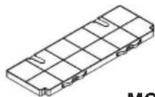
80cm54cm
MCFB83PL
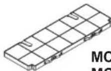
MCFB84STMCFB8
MCFB85PL
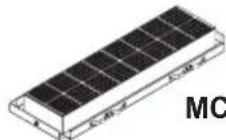
MCFB75PR
M8CKSL07
70 mm
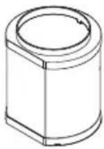
M8CKSL28
280 mm
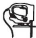
natural_image
Line drawing of a small electric iron with a handle and screw base (no text or symbols)
i
54cm
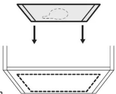
natural_image
Pure diagram of a mechanical or electrical component with arrows indicating direction, no text or symbols presentM8CKSL07
350 mm
M8CKSL28


B1

B2

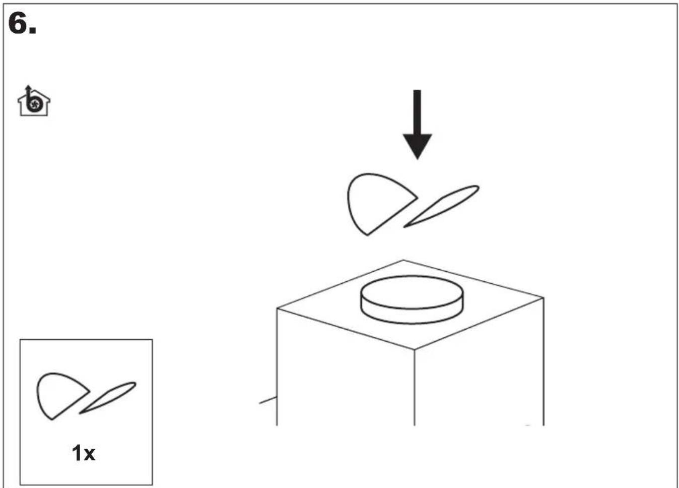
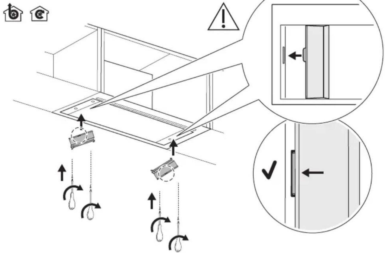
1.


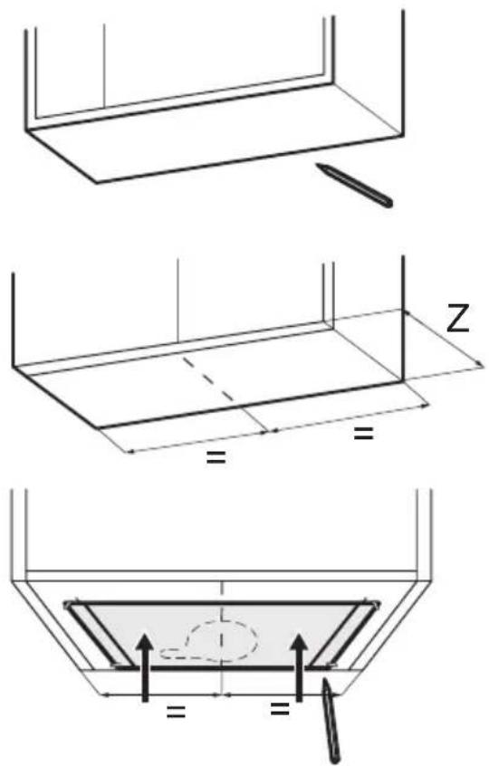
natural_image
Simple line drawing of a rectangular box with one corner and two horizontal lines inside (no text or symbols)
4.
natural_image
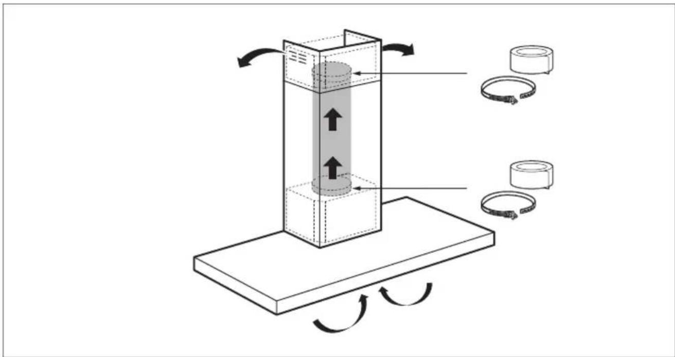
Technical line drawing of a mechanical component with internal channels and directional arrows indicating rotation (no text or symbols)5.
7.

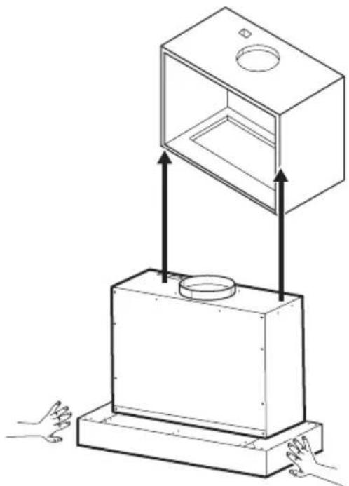
natural_image
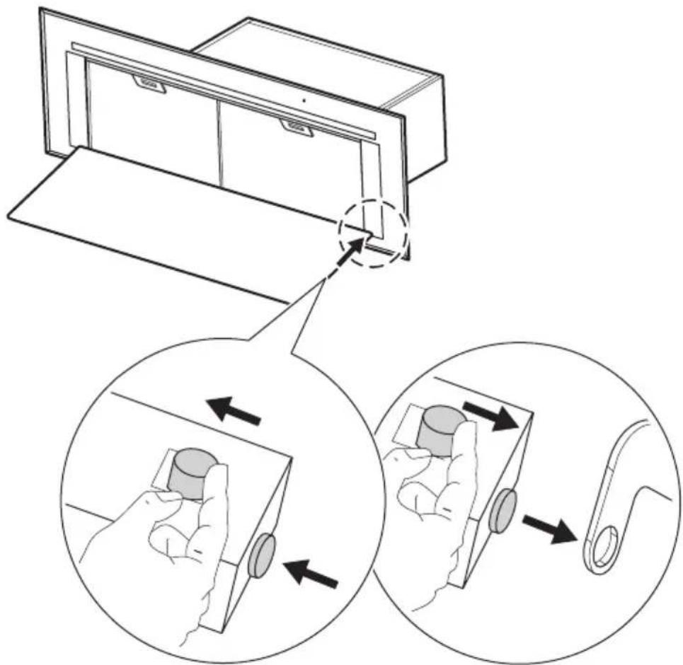
Diagram of a mechanical device with two boxes and a top box, showing hands interacting with the base (no text or symbols present)8.

11
natural_image
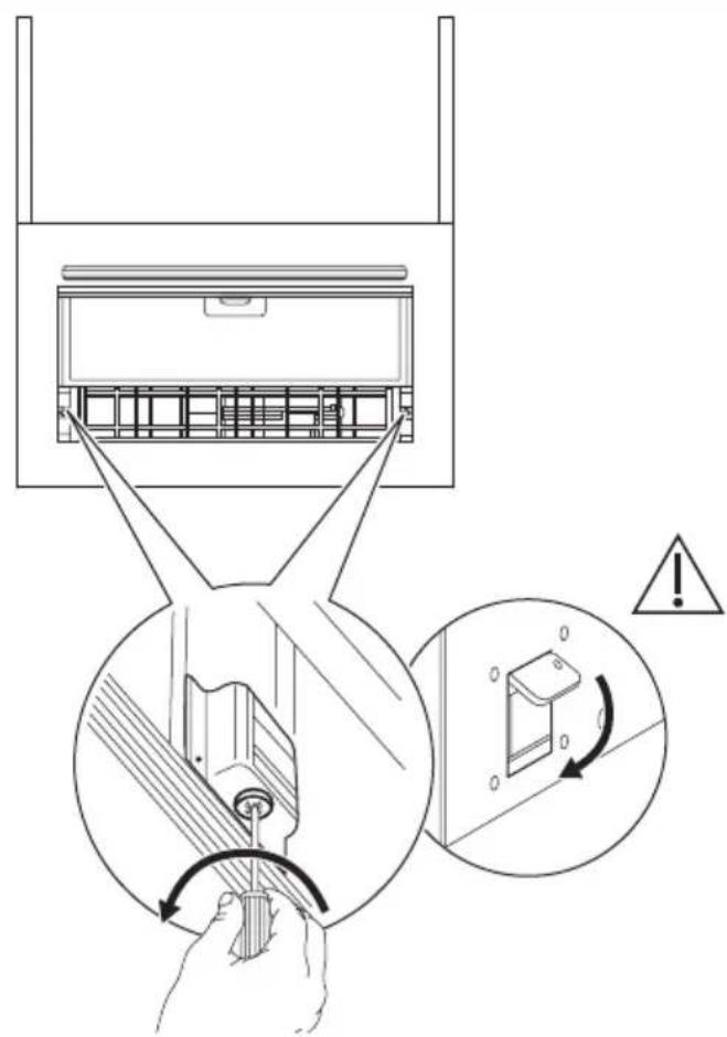
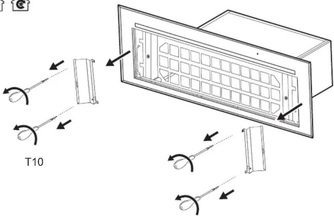
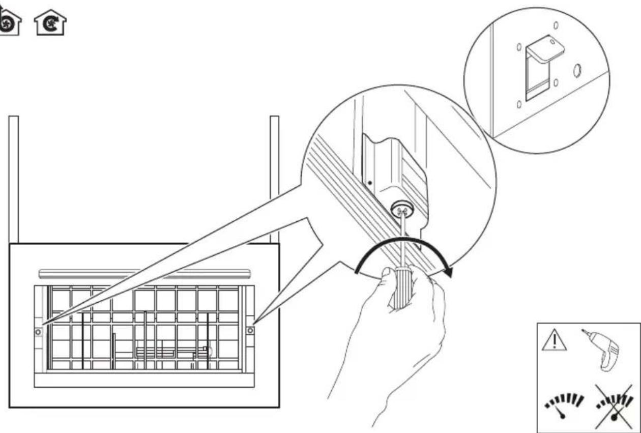
Technical line drawing of a mechanical component with internal channels and mounting holes (no text or symbols)12.1.
natural_image
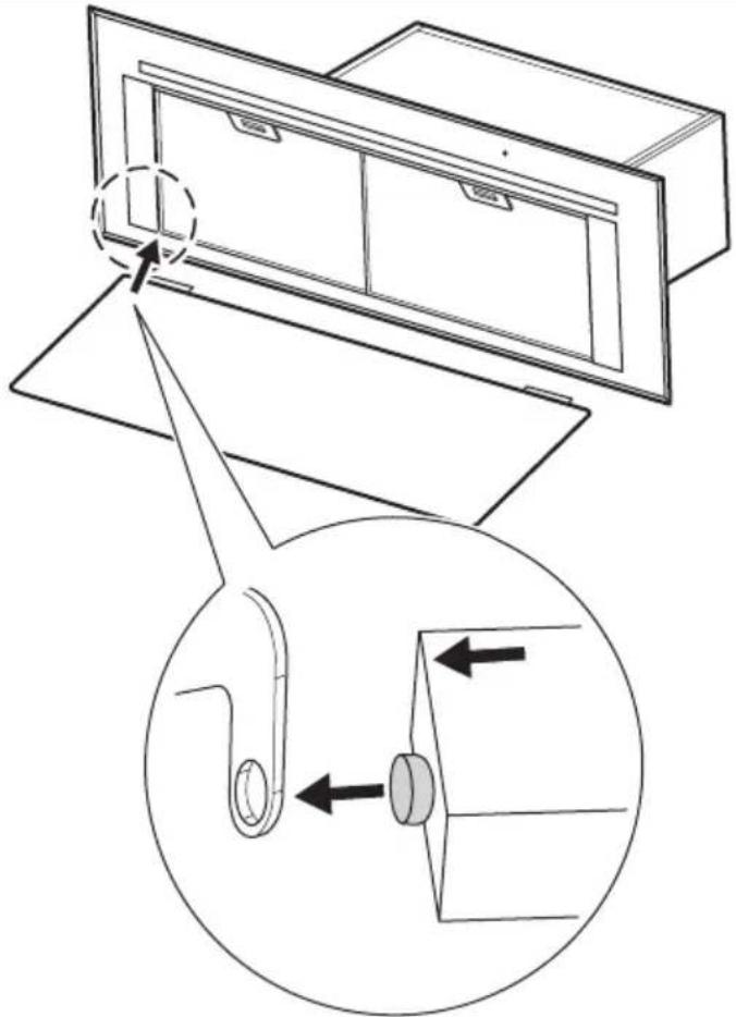
Technical line drawing of a door handle assembly with an inset showing a hook mechanism (no text or symbols)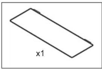
natural_image
Simple line drawing of a rectangular prism with label 'x1' (no other text or symbols)12.2.


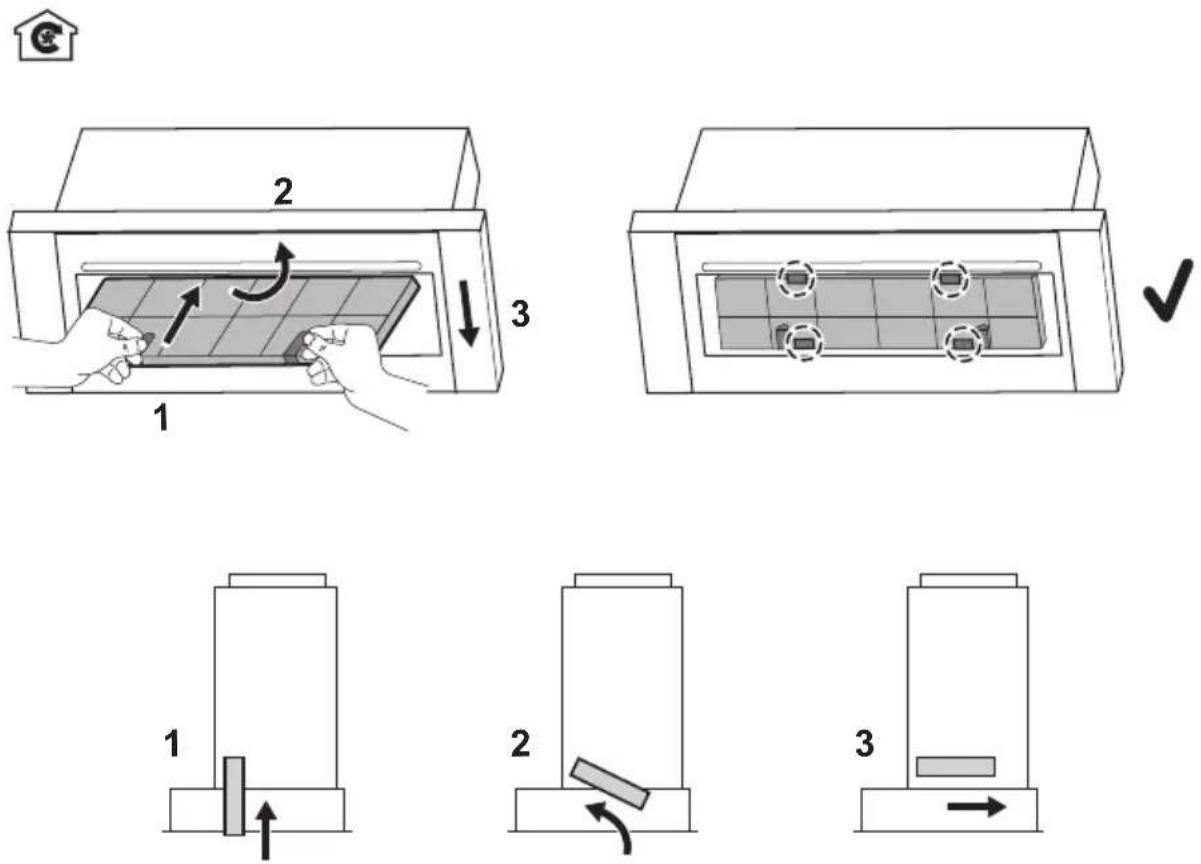
12.3.


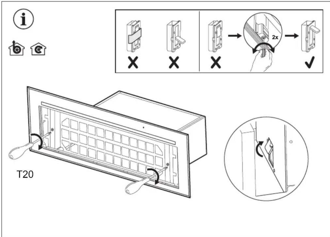
natural_image
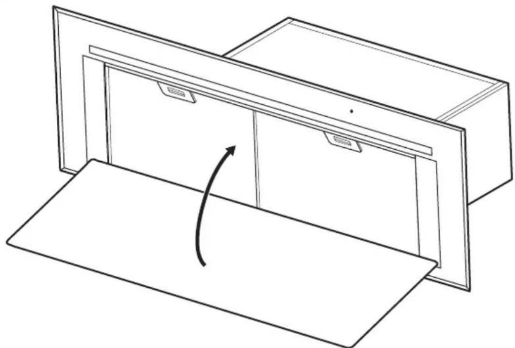
Line drawing of a cabinet with an arrow indicating rotation or movement (no text or symbols)13.


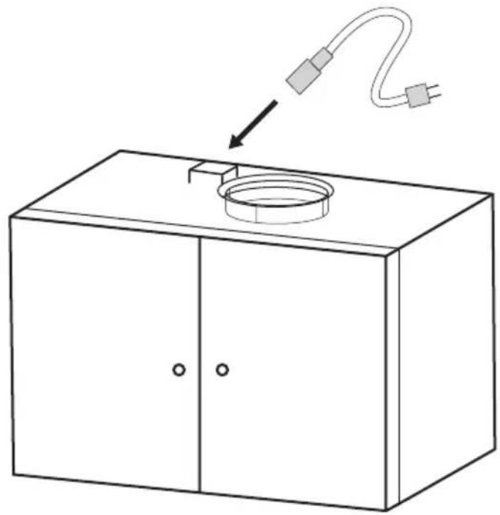
natural_image
Line drawing of a cabinet with a circular component and a cable, no text or symbols presenti