GWS18V-11PS Professional - Grinder BOSCH - Free user manual and instructions
Find the device manual for free GWS18V-11PS Professional BOSCH in PDF.

User questions about GWS18V-11PS Professional BOSCH
0 question about this device. Answer the ones you know or ask your own.
Ask a new question about this device
Download the instructions for your Grinder in PDF format for free! Find your manual GWS18V-11PS Professional - BOSCH and take your electronic device back in hand. On this page are published all the documents necessary for the use of your device. GWS18V-11PS Professional by BOSCH.
USER MANUAL GWS18V-11PS Professional BOSCH
natural_image
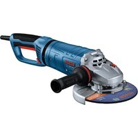
3D rendering of a gray and white electric grinder with a handle (no text or symbols visible)text_image
A ① (14) ② (12) ③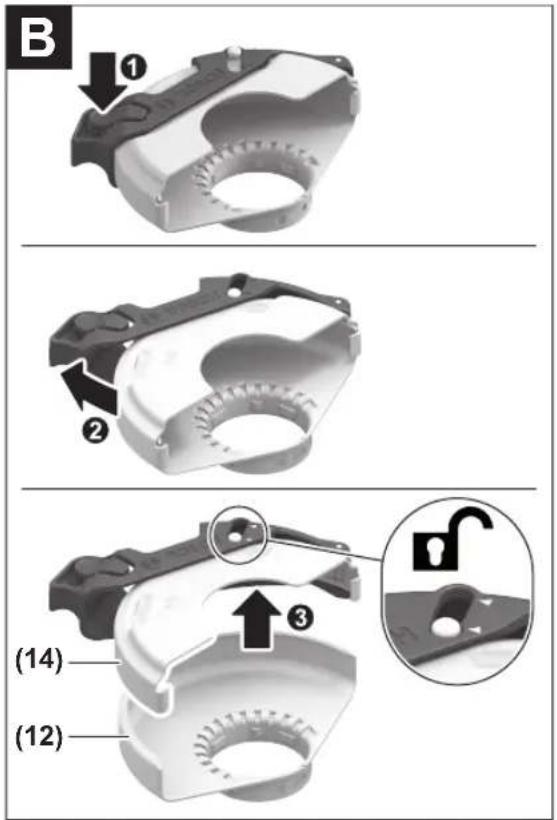
text_image
B ① ② ③ (14) (12)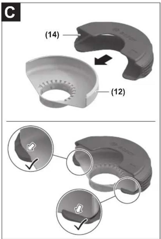
text_image
(14) (12)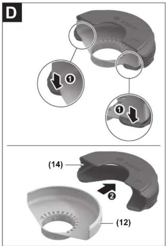
text_image
D ① ① (14) ② (12)4
text_image
Exploded view diagram of a cleaning or mechanical assembly with numbered parts and Chinese labels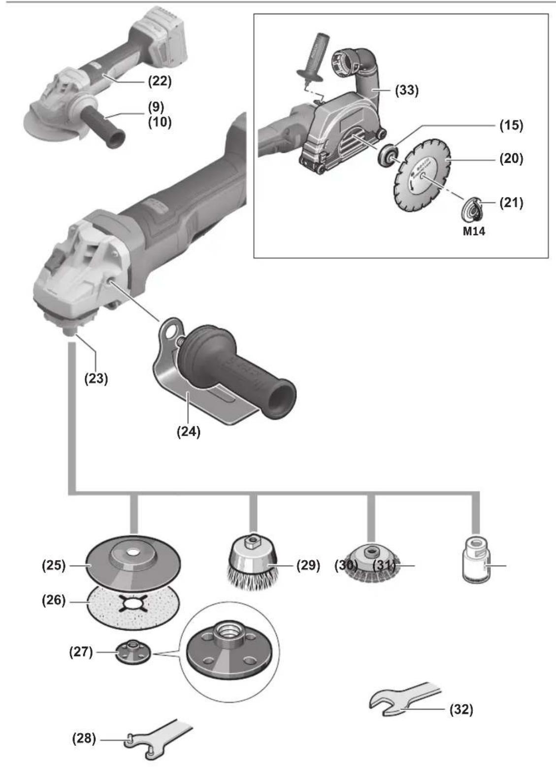
text_image
Diagram illustrating the step-by-step assembly of a power saw, showing tool positioning and angle adjustment.Deutsch
Sicherheitshinweise
natural_image
Mechanical diagram showing two rotating components with directional arrows indicating motion (no text or symbols)text_image
Technical diagram of a mechanical device with numbered components and directional arrow labeled ①text_image
Technical diagram of a mechanical component with numbered parts and directional arrow labeled '1'General Power Tool Safety Warnings
WARNING
Read all safety warnings, instructions, illustrations and specifica-
tions provided with this power tool. Failure to follow all instructions listed below may result in electric shock, fire and/or serious injury.
Save all warnings and instructions for future reference.
The term "power tool" in the warnings refers to your mains-operated (corded) power tool or battery-operated (cordless) power tool.
Work area safety
▶ Keep work area clean and well lit. Cluttered or dark areas invite accidents.
▶ Do not operate power tools in explosive atmospheres, such as in the presence of flammable liquids, gases or dust. Power tools create sparks which may ignite the dust or fumes.
▶ Keep children and bystanders away while operating a power tool. Distractions can cause you to lose control.
Electrical safety
▶ Do not expose power tools to rain or wet conditions. Water entering a power tool will increase the risk of electric shock.
Personal safety
▶ Stay alert, watch what you are doing and use common sense when operating a power tool. Do not use a power tool while you are tired or under the influence of drugs, alcohol or medication. A moment of inattention while operating power tools may result in serious personal injury.
▶ Use personal protective equipment. Always wear eye protection. Protective equipment such as a dust mask, non-skid safety shoes, hard hat or hearing protection used for appropriate conditions will reduce personal injuries.
▶ Prevent unintentional starting. Ensure the switch is in the off-position before connecting to power source and/or battery pack, picking up or carrying the tool. Carrying power tools with your finger on the switch or energising power tools that have the switch on invites accidents.
Remove any adjusting key or wrench before turning the power tool on. A wrench or a key left attached to a rotating part of the power tool may result in personal injury.
▶ Do not overreach. Keep proper footing and balance at all times. This enables better control of the power tool in unexpected situations.
▶ Dress properly. Do not wear loose clothing or jewellery. Keep your hair and clothing away from moving parts. Loose clothes, jewellery or long hair can be caught in moving parts.
If devices are provided for the connection of dust extraction and collection facilities, ensure these are connected and properly used. Use of dust collection can reduce dust-related hazards.
▶ Do not let familiarity gained from frequent use of tools allow you to become complacent and ignore tool safety principles. A careless action can cause severe injury within a fraction of a second.
Power tool use and care
▶ Do not force the power tool. Use the correct power tool for your application. The correct power tool will do the job better and safer at the rate for which it was designed.
▶ Do not use the power tool if the switch does not turn it on and off. Any power tool that cannot be controlled with the switch is dangerous and must be repaired.
▶ Disconnect the plug from the power source and/or remove the battery pack, if detachable, from the power tool before making any adjustments, changing accessories, or storing power tools. Such preventive safety measures reduce the risk of starting the power tool accidentally.
▶ Store idle power tools out of the reach of children and do not allow persons unfamiliar with the power tool or these instructions to operate the power tool. Power tools are dangerous in the hands of untrained users.
- Maintain power tools and accessories. Check for misalignment or binding of moving parts, breakage of parts and any other condition that may affect the power tool's operation. If damaged, have the power tool repaired before use. Many accidents are caused by poorly maintained power tools.
▶ Keep cutting tools sharp and clean. Properly maintained cutting tools with sharp cutting edges are less likely to bind and are easier to control.
▶ Use the power tool, accessories and tool bits etc. in accordance with these instructions, taking into account the working conditions and the work to be performed. Use of the power tool for operations different from those intended could result in a hazardous situation.
▶ Keep handles and grasping surfaces dry, clean and free from oil and grease. Slippery handles and grasping surfaces do not allow for safe handling and control of the tool in unexpected situations.
Battery tool use and care
▶ Recharge only with the charger specified by the manufacturer. A charger that is suitable for one type of battery pack may create a risk of fire when used with another battery pack.
▶ Use power tools only with specifically designated battery packs. Use of any other battery packs may create a risk of injury and fire.
When battery pack is not in use, keep it away from other metal objects, like paper clips, coins, keys, nails, screws or other small metal objects, that can make a connection from one terminal to another. Shorting the battery terminals together may cause burns or a fire.
▶ Under abusive conditions, liquid may be ejected from the battery; avoid contact. If contact accidentally occurs, flush with water. If liquid contacts eyes, additionally seek medical help. Liquid ejected from the battery may cause irritation or burns.
▶ Do not use a battery pack or tool that is damaged or modified. Damaged or modified batteries may exhibit unpredictable behaviour resulting in fire, explosion or risk of injury.
▶ Do not expose a battery pack or tool to fire or excessive temperature. Exposure to fire or temperature above 130^ C may cause explosion.
▶ Follow all charging instructions and do not charge the battery pack or tool outside the temperature range specified in the instructions. Charging improperly or at temperatures outside the specified range may damage the battery and increase the risk of fire.
Service
▶ Have your power tool serviced by a qualified repair person using only identical replacement parts. This will ensure that the safety of the power tool is maintained.
▶ Never service damaged battery packs. Service of battery packs should only be performed by the manufacturer or authorized service providers.
Safety warnings for angle grinder
Safety warnings common for grinding, sanding, wire brushing or cutting-off operations:
This power tool is intended to function as a grinder, sander, wire brush, hole cutter or cut-off tool. Read all safety warnings, instructions, illustrations and specifications provided with this power tool. Failure to follow all instructions listed below may result in electric shock, fire and/or serious injury.
▶ Operations such as polishing are not to be performed with this power tool. Operations for which the power tool was not designed may create a hazard and cause personal injury.
▶ Do not convert this power tool to operate in a way which is not specifically designed and specified by the tool manufacturer. Such a conversion may result in a loss of control and cause serious personal injury.
▶ Do not use accessories which are not specifically designed and specified by the tool manufacturer. Just because the accessory can be attached to your power tool, it does not assure safe operation.
The rated speed of the accessory must be at least equal to the maximum speed marked on the power tool. Accessories running faster than their rated speed can break and fly apart.
The outside diameter and the thickness of your accessory must be within the capacity rating of your power tool. Incorrectly sized accessories cannot be adequately guarded or controlled.
The dimensions of the accessory mounting must fit the dimensions of the mounting hardware of the power tool. Accessories that do not match the mounting hardware of the power tool will run out of balance, vibrate excessively and may cause loss of control.
Do not use a damaged accessory. Before each use inspect the accessory such as abrasive wheels for chips and cracks, backing pad for cracks, tear or excess wear, wire brush for loose or cracked wires. If power tool or accessory is dropped, inspect for damage or install an undamaged accessory. After inspecting and installing an accessory, position yourself and bystanders away from the plane of the rotating accessory and run the power tool at maximum no-load speed for one minute. Damaged accessories will normally break apart during this test time.
▶ Wear personal protective equipment. Depending on application, use face shield, safety goggles or safety glasses. As appropriate, wear dust mask, hearing protectors, gloves and workshop apron capable of stopping small abrasive or workpiece fragments. The eye protection must be capable of stopping flying debris generated by various applications. The dust mask or respirator must be capable of filtrating particles generated by the particular application. Prolonged exposure to high intensity noise may cause hearing loss.
▶ Keep bystanders a safe distance away from work area. Anyone entering the work area must wear personal protective equipment. Fragments of workpiece or of a broken accessory may fly away and cause injury beyond immediate area of operation.
▶ Hold the power tool by insulated gripping surfaces only, when performing an operation where the cutting tool may contact hidden wiring. Contact with a "live" wire will also make exposed metal parts of the power tool "live" and could give the operator an electric shock.
▶ Never lay the power tool down until the accessory has come to a complete stop. The spinning accessory may grab the surface and pull the power tool out of your control.
▶ Do not run the power tool while carrying it at your side. Accidental contact with the spinning accessory could snag your clothing, pulling the accessory into your body.
Regularly clean the power tool's air vents. The motor's fan will draw the dust inside the housing and excessive accumulation of powdered metal may cause electrical hazards.
22 | English
▶ Do not operate the power tool near flammable materials. Sparks could ignite these materials.
▶ Do not use accessories that require liquid coolants. Using water or other liquid coolants may result in electrocution or shock.
Kickback and related warnings:
Kickback is a sudden reaction to a pinched or snagged rotating wheel, backing pad, brush or any other accessory. Pinching or snagging causes rapid stalling of the rotating accessory which in turn causes the uncontrolled power tool to be forced in the direction opposite of the accessory's rotation at the point of the binding.
For example, if an abrasive wheel is snagged or pinched by the workpiece, the edge of the wheel that is entering into the pinch point can dig into the surface of the material causing the wheel to climb out or kick out. The wheel may either jump toward or away from the operator, depending on direction of the wheel's movement at the point of pinching. Abrasive wheels may also break under these conditions. Kickback is the result of power tool misuse and/or incorrect operating procedures or conditions and can be avoided by taking proper precautions as given below.
▶ Maintain a firm grip with both hands on the power tool and position your body and arms to allow you to resist kickback forces. Always use auxiliary handle, if provided, for maximum control over kickback or torque reaction during start-up. The operator can control torque reactions or kickback forces, if proper precautions are taken.
▶ Never place your hand near the rotating accessory. Accessory may kickback over your hand.
Do not position your body in the area where power tool will move if kickback occurs. Kickback will propel the tool in direction opposite to the wheel's movement at the point of snagging.
▶ Use special care when working corners, sharp edges, etc. Avoid bouncing and snagging the accessory. Corners, sharp edges or bouncing have a tendency to snag the rotating accessory and cause loss of control or kickback.
▶ Do not attach a saw chain woodcarving blade, segmented diamond wheel with a peripheral gap greater than 10 mm or toothed saw blade. Such blades create frequent kickback and loss of control.
Safety warnings specific for grinding and cutting-off operations:
▶ Use only wheel types that are specified for your power tool and the specific guard designed for the selected wheel. Wheels for which the power tool was not designed cannot be adequately guarded and are unsafe.
The grinding surface of centre depressed wheels must be mounted below the plane of the guard lip. An improperly mounted wheel that projects through the plane of the guard lip cannot be adequately protected.
The guard must be securely attached to the power tool and positioned for maximum safety, so the least
amount of wheel is exposed towards the operator. The guard helps to protect the operator from broken wheel fragments, accidental contact with wheel and sparks that could ignite clothing.
▶ Wheels must be used only for specified applications. For example: do not grind with the side of cut-off wheel. Abrasive cut-off wheels are intended for peripheral grinding, side forces applied to these wheels may cause them to shatter.
▶ Always use undamaged wheel flanges that are of correct size and shape for your selected wheel. Proper wheel flanges support the wheel thus reducing the possibility of wheel breakage. Flanges for cut-off wheels may be different from grinding wheel flanges.
▶ Do not use worn down wheels from larger power tools. A wheel intended for larger power tool is not suitable for the higher speed of a smaller tool and may burst.
When using dual purpose wheels always use the correct guard for the application being performed. Failure to use the correct guard may not provide the desired level of guarding, which could lead to serious injury.
Additional safety warnings specific for cutting-off operations:
Do not "jam" the cut-off wheel or apply excessive pressure. Do not attempt to make an excessive depth of cut. Overstressing the wheel increases the loading and susceptibility to twisting or binding of the wheel in the cut and the possibility of kickback or wheel breakage.
▶ Do not position your body in line with and behind the rotating wheel. When the wheel, at the point of operation, is moving away from your body, the possible kickback may propel the spinning wheel and the power tool directly at you.
When the wheel is binding or when interrupting a cut for any reason, switch off the power tool and hold it motionless until the wheel comes to a complete stop. Never attempt to remove the cut-off wheel from the cut while the wheel is in motion otherwise kickback may occur. Investigate and take corrective action to eliminate the cause of wheel binding.
▶ Do not restart the cutting operation in the workpiece. Let the wheel reach full speed and carefully re-enter the cut. The wheel may bind, walk up or kickback if the power tool is restarted in the workpiece.
▶ Support panels or any oversized workpiece to minimize the risk of wheel pinching and kickback. Large workpieces tend to sag under their own weight. Supports must be placed under the workpiece near the line of cut and near the edge of the workpiece on both sides of the wheel.
▶ Use extra caution when making a “pocket cut” into existing walls or other blind areas. The protruding wheel may cut gas or water pipes, electrical wiring or objects that can cause kickback.
▶ Do not attempt to do curved cutting. Overstressing the wheel increases the loading and susceptibility to twisting
or binding of the wheel in the cut and the possibility of kickback or wheel breakage, which can lead to serious injury.
Safety warnings specific for sanding operations:
▶ Use proper sized sanding disc paper. Follow manufacturers recommendations, when selecting sanding paper. Larger sanding paper extending too far beyond the sanding pad presents a laceration hazard and may cause snagging, tearing of the disc or kickback.
Safety warnings specific for wire brushing operations:
▶ Be aware that wire bristles are thrown by the brush even during ordinary operation. Do not overstress the wires by applying excessive load to the brush The wire bristles can easily penetrate light clothing and/or skin.
If the use of a guard is specified for wire brushing, do not allow any interference of the wire wheel or brush with the guard. Wire wheel or brush may expand in diameter due to work load and centrifugal forces.
Additional safety information

Wear safety goggles.

The protective guard must not be used for cutting. With a suitable adapter, the protective guard can also be used for cutting.

Hold the power tool firmly with both hands and make sure you have a stable footing. The power tool can be more securely guided with both hands.
For application tools with an internal thread, such as brushes and diamond annular cutters, attention must be paid to the max. thread length of the grinding spindle. The spindle end must not touch the base of the application tool.
▶ Use suitable detectors to determine if there are hidden supply lines or contact the local utility company for assistance. Contact with electric cables can cause fire and electric shock. Damaging gas lines can lead to explosion. Breaking water pipes causes property damage.
▶ Do not touch grinding and cutting discs until they have cooled down. The discs can become very hot while working.
▶ Release the On/Off switch and set it to the Off position when the power supply is interrupted, e.g. when the battery pack is removed. This prevents uncontrolled restarting.
▶ Secure the workpiece. A workpiece clamped with clamping devices or in a vice is held more secure than by hand.
▶ Store the application tools inside buildings, in a dry, frost-free room at a uniform temperature.
▶ Remove the application tools before transporting the power tool. This will allow you to avoid damage.
▶ Bonded cutting and grinding discs have an expiration date, after which the discs must no longer be used.
In case of damage and improper use of the battery, vapours may be emitted. The battery can set alight or explode. Ensure the area is well ventilated and seek medical attention should you experience any adverse effects. The vapours may irritate the respiratory system.
▶ Do not modify or open the battery. There is a risk of short-circuiting.
The battery can be damaged by pointed objects such as nails or screwdrivers or by force applied externally. An internal short circuit may occur, causing the battery to burn, smoke, explode or overheat.
▶ Only use the battery in the manufacturer's products. This is the only way in which you can protect the battery against dangerous overload.


Protect the rechargeable battery against heat, e.g. including prolonged sun exposure, fire, water, and moisture. There is a risk of explosion and short circuit.
Product Description and Specifications

Read all the safety and general instructions. Failure to observe the safety and general instructions may result in electric shock, fire and/or serious injury.
Please observe the illustrations at the beginning of this operating manual.
Intended use
The power tool is intended for cutting metal and stone materials, plastic and composite materials and for brushing metal and stone materials, roughing metal as well as making holes in stone materials using diamond annular cutters, without the use of water. Make sure that the correct protective guard is used (see "Operation", page 29).
Sufficient dust extraction must be provided when cutting stone.
With approved abrasive tools, the power tool can be used for sanding with sanding discs.
The power tool must not be used to grind stone materials with diamond grinding heads.
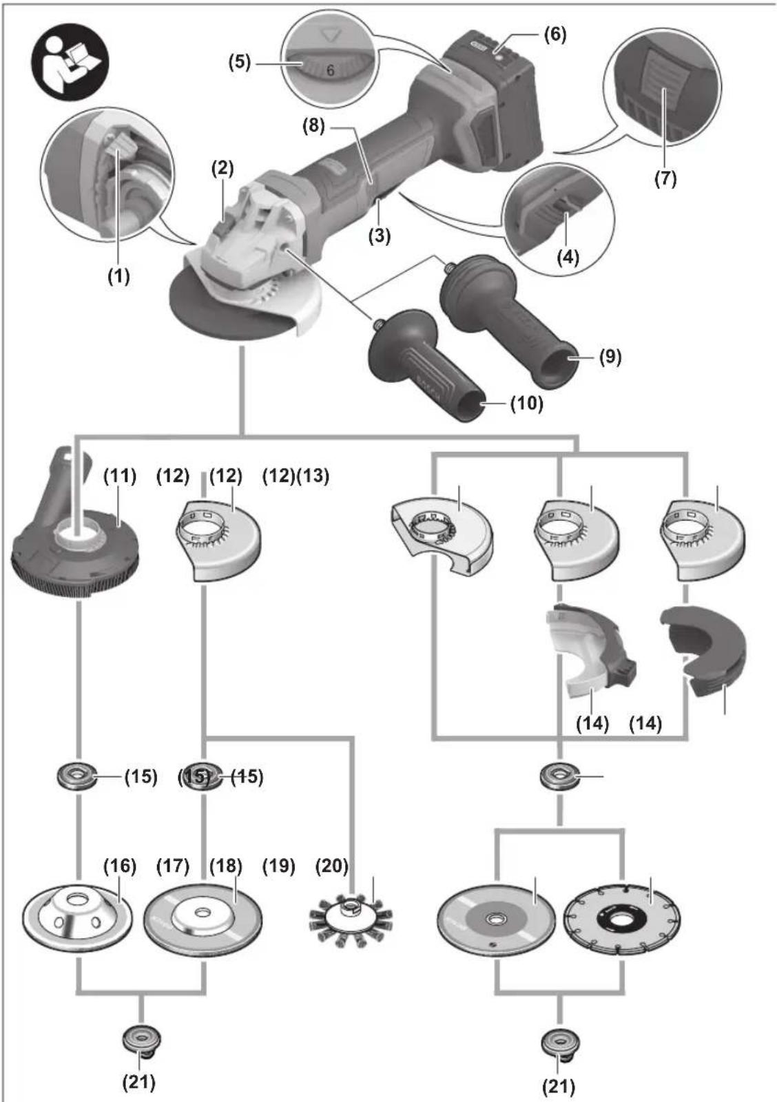
Product Features
The numbering of the product features refers to the diagram of the power tool on the graphics page.
(1) Unlocking lever for protective guard
(2) Spindle lock button
(3) On/off switch
(4) Unlocking lever for on/off switch
(5) Speed preselection thumbwheel
24 | English
(6) Rechargeable battery ^a
(7) Battery release button ^a)
(8) Button for rotating the gear head
(9) Vibration-damping auxiliary handle (insulated gripping surface)
(10) Standard auxiliary handle (insulated gripping surface) ^a)
(11) Extraction guard for grinding ^a)
(12) Protective guard for grinding
(13) Protective guard for cutting ^a)
(14) Cover for cutting
(15) Mounting flange with O-ring
(16) Carbide grinding head ^a)
(17) Grinding disc ^a)
(18) Disc brush (M14) ^a)
(19) Cutting disc ^a)
(20) Diamond cutting disc ^a)
(21) Quick-clamping nut with bar (M14)
(22) Handle (insulated gripping surface)
(23) Grinding spindle
(24) Hand guard ^a)
(25) Rubber sanding pad ^a)
(26) Sanding sheet ^3
(27) Round nut ^a)
(28) Two-pin spanner for clamping nut
(29) Cup brush ^a)
(30) Conical brush ^a)
(31) Diamond annular cutter ^a)
(32) Open-ended spanner ^a)
(33) Extraction guard for cutting with cutting guides ^a)
a) This accessory is not part of the standard scope of delivery.
Technical Data
Angle grinder GWS18V-11PS
| Article number | 3 601 JN4 3.. | |
| Rated voltage V= 18 | ||
| Rated no-load speed ^1) | min ^-1 | 9000 |
| Speed adjustment range min | ^-1 | 3000–9000 |
| Max. grinding disc diameter/rubber sanding pad diameter | mm 125 | |
| Grinding spindle thread M 14 | ||
| Max. thread length of grinding spindle | mm 22 | |
| KickBack Control ● | ||
| Restart protection ● | ||
| Run-out brake ● | ||
| Drop Control ● | ||
Angle grinder GWS18V-11PS
| Speed preselection ● | |
| Weight ^B) | kg 1.9 |
| Recommended ambient temperature during charging | °C 0 to +35 |
| Permitted ambient temperature during operation ^C) and during storage | °C -20 to +50 |
| Compatible rechargeable batteries | GBA18V...GBA 18V...ProCORE18V...EXPERT18V...EXBA18V...CORE18V... |
| Recommended rechargeable batteries for maximum performance | GBA 18V...≥4.0AhProCORE18V...≥4.0AhEXPERT18V... |
| Recommended battery chargers GAL18... | GAL 18...GAL 36...GAL12V/18...GAL 12V/18...GAX 18...EXAL18... |
A) Rated no-load speed for the selection of appropriate application tools in accordance with EN IEC 62841-2-3. The actual no-load speed is lower for safety reasons and according to production tolerances.
B) With auxiliary handle (10), protective guard for cutting (13), mounting flange (15), quick-clamping nut (21), without rechargeable battery (you can find the battery weight at www.bosch-professional.com)
C) Limited performance at temperatures < 0 °C
Values can vary depending on the product, scope of application and environmental conditions. To find out more, visit www.bosch-professional.com/wac.
Noise/Vibration Information
Noise emission values determined according to EN IEC 62841-2-3.
Typically, the A-weighted noise level of the power tool is: Sound pressure level 83 dB(A); sound power level 91 dB(A). Uncertainty K = 3 dB.
Wear hearing protection!
Vibration values a_h (continuous vibrations), p_F (repeated shock vibrations) and uncertainty K determined according to EN IEC 62841-2-3:
Surface grinding (roughing) and cut-off grinding:
$$ a _ {n, A G / C O} = 5. 2 \mathrm{m} / \mathrm{s} ^ {2} (K = 1. 5 \mathrm{m} / \mathrm{s} ^ {2}), $$
$$ p _ {F, A G / C O} = 1 3 6. 7 \mathrm{m} / \mathrm{s} ^ {2} (K = 4. 5 \mathrm{m} / \mathrm{s} ^ {2}) $$
Disc sanding:
$$ a _ {n, D S} = 2. 0 \mathrm{m} / \mathrm{s} ^ {2} (K = 1. 5 \mathrm{m} / \mathrm{s} ^ {2}), $$
$$ p _ {F, D S} = 6 0. 9 \mathrm{m} / \mathrm{s} ^ {2} (K = 4. 9 \mathrm{m} / \mathrm{s} ^ {2}) $$
Grinding thin metal sheets or other materials that tend to easily vibrate with a large surface area can cause the noise emission value to increase by up to 15 dB. Suitable, heavy damping mats can reduce
the increased noise emissions. Increased noise emissions must be taken into consideration, both for the risk assessment of the noise output and for selecting suitable hearing protection.
The vibration level and noise emission value given in these instructions have been measured in accordance with a standardised measuring procedure and may be used to compare power tools. They may also be used for a preliminary estimation of vibration and noise emissions.
The stated vibration level and noise emission value represent the main applications of the power tool. However, if the power tool is used for other applications, with different accessories or is poorly maintained, the vibration level and noise emission value may differ. This may significantly increase the vibration and noise emissions over the total working period.
To estimate vibration and noise emissions accurately, the times when the tool is switched off or when it is running but not actually being used should also be taken into account. This may significantly reduce vibration and noise emissions over the total working period.
Implement additional safety measures to protect the operator from the effects of vibration, such as servicing the power tool and accessories, keeping their hands warm, and organising workflows correctly.
Kickback control

If there is a sudden kickback in the power tool, e.g. jamming in a separating cut, the power supply to the motor will be interrupted electronically.
To restart the tool, set the On/Off switch (3) to the "off" position and then switch the power tool on again.
Restart protection

The restart protection feature prevents the power tool from uncontrolled starting after the power supply to it has been interrupted.
To restart the tool, set the on/off switch (3) to the off position and then switch the power tool
on again.
Run-out brake

The power tool is fitted with an electronic run-out brake. When the power tool is switched off or the power supply is interrupted, the abrasive tool is brought to a complete stop within a few seconds.
Drop control
The integrated drop control switches the power tool off as soon as it hits the floor. To restart the tool, set the On/Off switch (3) to the "off" position and then switch the power tool on again.
Data logging

Tool data logging is enabled in this tool.
Speed preselection
You can preselect the required speed using the speed preselection thumbwheel (5), even during operation. The information in the table below describes the recommended values.
Material Application Application tool Thumbwheel position
| Metal Removing paint Sanding sheet 2-3 | |
| Metal Brushing, removing rust Cup brush, abrasive disc 3 | |
| Stainless steel Grinding Grinding disc/fibre disc 4-6 | |
| Metal Rough grinding Grinding disc 6 | |
| Metal Cutting Cutting disc | 6 |
| Stone Cutting Diamond cutting disc | 6 |
The rated speed of the accessory must be at least equal to the maximum speed marked on the power tool. Accessories running faster than their rated speed can break and fly apart.
| Level | [min-1] |
| Speed preselection | |
| 1 | 3000 |
| 2 | 4500 |
| 3 | 5400 |
| 4 | 6200 |
| 5 | 7000 |
| Level | [min-1] |
| Speed preselection | |
| 6 | 9000 |
The values specified for speed levels are guide values.
Rechargeable battery
Bosch sells some cordless power tools without a rechargeable battery. You can tell whether a rechargeable battery is included with the power tool by looking at the packaging.
26 | English
Charging the battery
▶ Use only the chargers listed in the technical data. Only these chargers are matched to the lithium-ion battery of your power tool.
Note: Lithium-ion rechargeable batteries are supplied partially charged according to international transport regulations. To ensure full rechargeable battery capacity, fully charge the rechargeable battery before using your tool for the first time.
Inserting the Battery
Push the charged battery into the battery holder until it clicks into place.
Removing the Battery
To remove the rechargeable battery, press the battery release button and pull the battery out. Do not use force to do this.
The rechargeable battery has two locking levels to prevent the battery from falling out if the battery release button is pressed unintentionally. The rechargeable battery is held in place by a spring when fitted in the power tool.
Battery charge indicator
Note: Not all battery types have a battery charge indicator. The green LEDs on the battery charge indicator indicate the state of charge of the battery. For safety reasons, it is only possible to check the state of charge when the power tool is not in operation.
Press the button for the battery charge indicator or to show the state of charge. This is also possible when the battery is removed.
If no LED lights up after pressing the button for the battery charge indicator, then the battery is defective and must be replaced.
Rechargeable battery type GBA 18V... | GBA18V...


LED Capacity
| 3× continuous green light 60-100% |
| 2× continuous green light 30-60% |
| 1× continuous green light 5-30% |
| 1× flashing green light 0-5% |
Battery model ProCORE18V... | EXPERT18V... | EXBA18V... | CORE18V...


LED Capacity
| 5 × continuous green light 80–100 % |
| 4 × continuous green light 60–80 % |
| 3 × continuous green light 40–60 % |
LED Capacity
| 2 × continuous green light 20–40 % |
| 1 × continuous green light 5–20 % |
| 1 × flashing green light 0–5 % |
Battery defect risk detection
EXPERT18V... | EXBA18V...
In addition to the state of charge of the rechargeable battery, the LEDs on the battery charge indicator can also indicate the risk of a battery defect.
To activate the function, press and hold the button for the battery charge indicator for 3 seconds. The analysis of the battery is signalled by a moving light on the battery charge indicator. The result of is shown on the battery charge indicator.
1 LED: The rechargeable battery has a high defect risk. Performance and runtime may
already be reduced. Replacing the rechargeable battery is recommended.

5 LEDs: The rechargeable battery is in good condition and has a low defect risk.
Please note: The rechargeable battery defect risk assessment works in a binary manner and offers a simplified status assessment, indicating either that the rechargeable battery is in good condition or that the rechargeable battery has an increased defect risk. A percentage of the battery status is not shown.
Recommendations for Optimal Handling of the Battery
Protect the battery against moisture and water.
Only store the battery within a temperature range of -20 to 50 °C. Do not leave the battery in your car in the summer, for example.
Occasionally clean the ventilation slots on the battery using a soft brush that is clean and dry.
A significantly reduced operating time after charging indicates that the battery has deteriorated and must be replaced.
Follow the instructions on correct disposal.
Fitting
Fitting Protective Equipment
Before carrying out any work on the power tool (e.g. maintenance, tool change etc.), remove the battery from the power tool. There is risk of injury from unintentionally pressing the on/off switch.
Note: If the grinding disc breaks during operation or the holding fixtures on the protective guard/power tool become damaged, the power tool must be sent to the after-sales service immediately; see the "After-Sales Service and Application Service" section for addresses.
Protective guard for grinding
natural_image
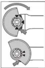
Mechanical diagram showing two cross-sectional views of a mechanical component with rotational arrows (no text or symbols)Place the protective guard (12) onto the holder on the power tool until the coding cams of the protective guard are aligned with the holder. When doing so, press and hold the unlocking lever (1).
Press the protective guard (12) onto the spindle collar until the shoulder of the protective guard is sitting on the flange of the power tool and rotate the protective guard until it audibly clicks
into place.
Adjust the position of the protective guard (12) to meet the requirements of the operation. To do this, push the unlocking lever (1) upward and rotate the protective guard (12) into the required position.
▶ Always position the protective guard (12) such that the two cams on the unlocking lever (1) engage in the corresponding openings on the protective guard (12).
▶ Adjust the protective guard (12) such that sparking in the direction of the operator is prevented.
The protective guard (12) must only be able to be rotated in the direction of the accessory while the unlocking lever (1) is actuated. Otherwise, the power tool must not be used any more under any circumstances and must be sent to the after-sales service.
Note: The coding cams on the protective guard (12) ensure that only a protective guard that is suitable for the power tool can be fitted.
Extraction guard for sanding
For low-dust grinding of paints, lacquers and plastics in conjunction with carbide grinding heads (16), you can use the extraction guard (11). The extraction guard (11) is not suitable for machining metal.
A suitable Bosch dust extractor can be connected to the extraction guard (11). To do so, insert the vacuum hose with dust extraction adapter into the provided receiving connection of the extraction guard.
Protective guard for cutting
For cutting, always use the protective guard for cutting (13) or the protective guard for grinding (12) together with the cover for cutting (14).
▶ Provide sufficient dust extraction when cutting stone.
The protective guard for cutting (13) is fitted in the same way as the protective guard for grinding (12).
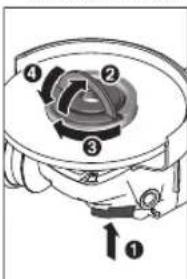
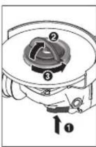
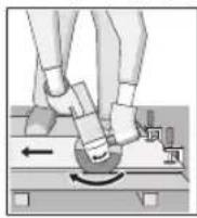
Metal cover for cutting
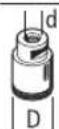
Fit the metal cover for cutting (14) on the protective guard for grinding (12) (see figure A): Swivel the tool retainer back (①). Attach the cover (14) to the protective guard for grinding (12) (②). Press the tool retainer firmly into place on the protective guard (12) (③).
To remove the cover (see figure B), press the button on the tool retainer (①) and swivel it back (②). Remove the cover (14) from the protective guard (12) (③).
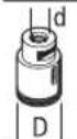
Plastic cover for cutting
Attach the plastic cover for cutting (14) to the protective guard for grinding (12) (see figure C). The cover (14) audibly and visually engages on the protective guard (12). To remove the cover (see figure D), unlock the cover (14) on the left- or right-hand side of the protective guard (12) (①) and remove the cover (②).
Extraction guard for cutting with a guide block
The extraction guard for cutting with a cutting guide (33) is fitted in the same way as the protective guard for grinding. By securing the auxiliary handle (10)/(9) with the clip through the extraction guard on the gearbox housing, the power tool is firmly attached to the extraction guard. A suitable Bosch dust extractor can be connected to the extraction guard with a cutting guide (33). To do so, insert the vacuum hose with dust extraction adapter into the provided receiving connection of the extraction guard.
Note: The friction generated by the dust in the vacuum hose and accessory during extraction causes an electrostatic charge that the user may experience as static discharge (depending on environmental factors and their physiological state). Bosch generally recommends using an anti-static vacuum hose (accessory) to vacuum up fine dust and dry materials.
Hand guard
▶ Always fit the hand guard (24) when working with the rubber sanding pad (25) or with the cup brush/conical brush/diamond annular cutter.
Attach the hand guard (24) to the auxiliary handle (10)/(9).
Standard auxiliary handle/low-vibration auxiliary handle Screw the auxiliary handle (10)/(9) on the right or left of the machine head depending on the working method.
▶ Do not operate your power tool without the auxiliary handle (10)/(9).
▶ Do not continue to use the power tool if the auxiliary handle (10)/(9) is damaged. Do not make any alterations to the auxiliary handle (10)/(9).

The low-vibration auxiliary handle (9) reduces vibration, enabling the tool to be used safely and more comfortably.
Fitting the Abrasive Tools
Before carrying out any work on the power tool (e.g. maintenance, tool change etc.), remove the battery from the power tool. There is risk of injury from unintentionally pressing the on/off switch.
▶ Do not touch grinding and cutting discs until they have cooled down. The discs can become very hot while working.
Clean the grinding spindle (23) and all the parts to be fitted. Lock the grinding spindle with the spindle lock button (2) before clamping and releasing the abrasive tools.
▶ Do not press the spindle lock button while the grinding spindle is moving. The power tool may become damaged if you do this.
28 | English
Grinding/Cutting Disc
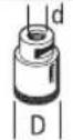
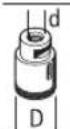
Pay attention to the dimensions of the abrasive tools. The diameter of the hole must match that of the mounting flange. Do not use an adapter or reducer.
When using diamond cutting discs, ensure that the arrow indicating the direction of rotation on the diamond cutting disc matches the direction of rotation of the power tool (see the direction of rotation arrow on the machine head).
See the graphics page for fitting instructions.
Use the quick-clamping nut (21) to secure the grinding/cutting disc without the need for additional tools.
Only use the quick-clamping nut (21) for grinding/cutting discs up to a maximum diameter of 125 mm.
▶ The quick-clamping nut (21) may be used only for grinding or cutting discs.
▶ Only use quick-clamping nuts (21) that are in good working order and not damaged.
When screwing on, make sure that the printed side of the quick-clamping nut (21) is not facing the grinding disc.
▶ Always secure a grinding/cutting disc using only the quick-clamping nut (21) supplied.
text_image
Technical diagram of a mechanical device with numbered components and directional arrow indicating rotation or movement.Press the spindle lock button (2) to lock the grinding spindle. To tighten the quick-clamping nut (21), fold up the bar and turn the quick-clamping nut firmly clockwise. Then fold down the bar to secure the quick-clamping nut. It is not sufficient to tighten the disc along the edge.
text_image
Technical diagram of a mechanical component with numbered parts and directional arrow labeled 'O'Quick-clamping nuts (21) that are properly secured and not damaged can be removed by hand. To do this, fold up the bar and turn the quick-clamping nut firmly anticlockwise. If the quick-clamping nut is stuck, do not attempt to loosen it with a tool – always use a two-pin spanner.
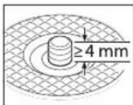
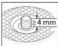
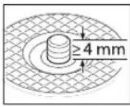
After fitting the hub flange and the grinding/cutting disc, the free thread length of the grinding spindle must be at least 4 mm.
Ensure that the abrasive tool is firmly seated, so that it does not twist away
from the spindle in the runout of the power tool.
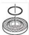
A plastic part (O-ring) is fitted around the cent-ring collar in the hub flange (15). If the O-ring is missing or damaged, the hub flange (15) must be replaced before operation can resume.
▶ After fitting the abrasive tool, check that the abrasive tool is fitted correctly and can turn freely before
switching on the power tool. Make sure that the abrasive tool does not brush against the protective guard or other parts.
Approved abrasive tools
You can use all the abrasive tools mentioned in these operating instructions.
The permissible speed [min^-1] or the circumferential speed [m/s] of the abrasive tools used must at least match the values given in the table.
It is therefore important to observe the permissible rotational/circumferential speed on the label of the abrasive tool.

text_image
max. [mm] [mm] [°] D b s d a [min -1] [m/s]
125 7.2 - 22.2 - 9000 80

125 4.2 - 22.2 - 9000 80

125----900080

75 30 - M 14 - 9000 80

125 24 - M14 - 9000 80 125 19 - 22.2 - 9000 80

125--M 14-900080
83--M 14-9000 80

125 6 10 22.2 > 0 9000 80
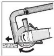
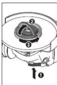
Rotating the Gear Head (see figure E)
Before carrying out any work on the power tool (e.g. maintenance, tool change etc.), remove the battery from the power tool. There is risk of injury from unintentionally pressing the on/off switch.
You can rotate the gearing 90° to the left or right relative to the handle. In this way, the on/off switch (3) can be brought into a more favourable handling position for particular applications, e.g. for cutting operations or for left-handed tool users.
Set the on/off switch (3) to the "Off" position.
Press the (8) button and turn the gearing to the required position.
The on/off switch (3) can only be activated if the gearing is in the correct position.
Dust Reduction
Do not perform work without taking dust-reducing measures. Depending on the intended application, the power tool can be combined with a dust-reducing accessory together with a dust extractor, (see "Extraction guard for sanding", page 27), (see "Extraction guard for cutting with a guide block", page 27).
Always use suitable breathing protection. The regulations on the materials being machined that apply in the country of use must be observed.
- Avoid dust accumulation at the workplace. Dust can easily ignite.
Requirements for the Dust Extractor
| Recommended hose nominal diameter | mm | 35 |
| Required vacuum pressure ^A) | mbar | ≥230 |
| hPa | ≥230 | |
| Required flow rate ^A) | l/s | ≥36 |
| m ^3 /h | ≥129.6 |
Recommended filter efficiency Dust class M B)
A) Power value at the power tool's dust extractor connection
B) According to IEC/EN 60335-2-69
Refer to the dust extractor's instructions. If there is reduced suction power, stop working and eliminate the cause.
Operation
▶ Do not load the power tool so heavily that it comes to a stop.
Before carrying out any work on the power tool (e.g. maintenance, tool change etc.), remove the battery from the power tool. There is risk of injury from unintentionally pressing the on/off switch.
▶ Exercise caution when cutting slots in structural walls; see the "Information on structural design" section.
▶ Clamp the workpiece if it is not secure under its own weight.
▶ If the power tool has been subjected to a heavy load, continue to run it at no-load for several minutes to cool down the accessory.
▶ Do not use the power tool with a cut-off stand.
▶ Do not touch grinding and cutting discs until they have cooled down. The discs can become very hot while working.
Working Advice
Rough grinding
▶ Always use the protective guard for grinding (12) when rough grinding with bonded abrasives.
▶ Never use cutting discs for rough grinding.
When rough grinding, the protective guard for cutting (13) or the protective guard for grinding (12) with a fitted cover for cutting (14) can impact the workpiece and lead to a loss of control.
The best rough grinding results are achieved with a set angle of 30^ to 40^ . Move the power tool back and forth with moderate pressure. This will ensure that the workpiece does not become too hot or discolour and that grooves are not formed.
The protective guard for cutting (13) or the protective guard for grinding (12) with a fitted cover for cutting (14) must be used when using bonded discs which are approved for cutting and grinding.
Surface grinding with flap disc
▶ Always use the protective guard for grinding (12) when grinding with the flap disc.
The flap disc (accessory) enables you to machine curved surfaces and profiles. Flap discs have a considerably longer service life, lower noise levels and lower grinding temperatures than conventional grinding discs.
Surface grinding with sanding disc
▶ Always fit the hand guard (24) when working with the rubber sanding pad (25).
Grinding with a sanding disc can be done without a protective guard.
See the graphics page for fitting instructions.
Screw on the round nut (27) and tighten it with the two-pin spanner.
Cup brush/disc brush/conical brush
▶ Always use the protective guard for grinding (12) when brushing with disc brushes. Brushing with cup brushes/conical brushes can be performed without the protective guard.
▶ Always fit the hand guard (24) when working with the cup brush or conical brush.
The wires of the disc brush can get caught on the protective guard and break, if the maximum permitted dimensions of the disc brushes are exceeded.
See the graphics page for fitting instructions.
The cup brush/conical brush/disc brush with M14 thread must be screwed onto the grinding spindle until it rests firmly against the grinding spindle flange at the end of the grinding spindle thread. Tighten the cup brush/conical brush/disc brush with an open-ended spanner.
Cutting Metal
For cutting metal with bonded cutting discs or diamond cutting discs, always use the protective guard for cutting (13) or the protective guard for grinding (12) with a fitted cover for cutting (14).
When using the protective guard for grinding (12) for cutting work with bonded cutting discs, there is an increased risk of being exposed to sparks, particles and disc fragments if the disc breaks.
When carrying out abrasive cutting, use a moderate feed that is suited to the material being machined. Do not exert pressure on the cutting disc and do not tilt or swing the power tool.
30 | English
Do not attempt to reduce the speed of a cutting disc coming to a stop by applying pressure from the side.
The power tool must always work in an up-grinding motion. Otherwise there is a risk that it will be pushed uncontrolled out of the cut. For best results when cutting profiles and rectangular tubing, start at the smallest cross section.
Cutting stone
For cutting stone with bonded cutting discs or diamond cutting discs for concrete/stone, always use the extraction guard for cutting with a cutting guide (33) or the protective guard for cutting (13) or the protective guard for grinding (12) with a fitted cover for cutting (14).
▶ Provide sufficient dust extraction when cutting stone.
▶ Wear a dust mask.
▶ The power tool may be used only for dry cutting/grinding.
When using the protective guard for cutting (13), the protective guard for grinding (12) or the protective guard for grinding (12) with a fitted cover for cutting (14) for cutting and grinding applications in concrete or masonry, there is an increased dust load and an increased risk of losing control of the power tool, which can lead to kickback.
For cutting stone, it is best to use a diamond cutting disc. When using the extraction guard for cutting with a cutting guide (33), the dust extractor must be approved for extracting stone dust. Suitable dust extractors are available from Bosch.
Switch on the power tool and position it with the front part of the cutting guide on the workpiece. Move the power tool with a moderate feed motion that is suited to the material being machined.
When cutting especially hard materials such as concrete with a high pebble content, the diamond cutting disc can overheat and become damaged as a result. This is clearly indicated by circular sparking, rotating with the diamond cutting disc.
If this happens, stop cutting and allow the diamond cutting disc to cool down by running the power tool for a short time at maximum speed with no load.
If work is noticeably slower and with circular sparking, this indicates that the diamond cutting disc has become blunt. You can resharpen the disc by briefly cutting into abrasive material (e.g. lime-sand brick).
Cutting other materials
For cutting materials such as plastic, composite materials, etc. with bonded cutting discs or Carbide Multi Wheel cutting discs, always use the protective guard
for cutting (13) or the protective guard for grinding (12) with a fitted cover for cutting (14). You can achieve improved dust extraction by using the extraction guard with a cutting guide (33).
Working with Diamond Annular Cutters
▶ Only use dry diamond annular cutters.
▶ Always fit the hand guard (24) when working with diamond annular cutters.
Do not place the diamond annular cutter parallel to the workpiece. Plunge it into the workpiece at an angle and in a circular motion. This will allow you to achieve optimal cooling and ensure a longer tool life for the diamond annular cutter.
Information on structural design
Recesses in load-bearing walls are subject to country-specific regulations. These regulations must be observed under all circumstances. Seek advice from the responsible structural engineer, architect or construction supervisor before starting work.
Start-Up
Switching On/Off
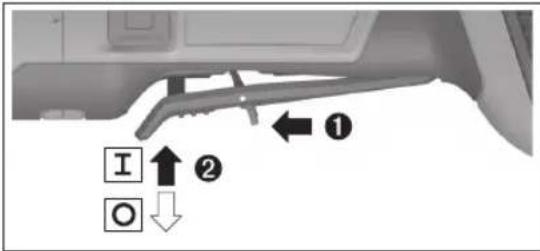
text_image
I O ① ②To start the power tool, push the unlocking lever (4) forwards and then push the on/off switch (3) up.
To switch off the power tool, release the on/off switch (3).
▶ Always check abrasive tools before using them. The abrasive tool must be fitted properly and be able to move freely. Carry out a test run for at least one minute with no load. Do not use abrasive tools that are damaged, run untrue or vibrate during use. Damaged abrasive tools can burst apart and cause injuries.
Maintenance and Service
Maintenance and Cleaning
▶ Before carrying out any work on the power tool (e.g. maintenance, tool change etc.), remove the battery from the power tool. There is risk of injury from unintentionally pressing the on/off switch.
▶ To ensure safe and efficient operation, always keep the power tool and the ventilation slots clean.
Store and handle the accessories carefully.
After-Sales Service and Application Service
Great Britain
Tel. Service: (0344) 7360109
You can find the link to our service addresses and warranty conditions on the last page.
In all correspondence and spare parts orders, please always include the 10-digit article number given on the nameplate of the product.
Disposal
Power tools, rechargeable batteries, accessories and packaging should be sorted for environmental-friendly recycling.
Do not dispose of power tools and batteries/re-chargeable batteries into household waste!
Only for EU countries and United Kingdom:
Electrical and electronic equipment or used batteries that are no longer suitable for use must be collected separately and disposed of in an environmentally friendly manner. Use the designated collection systems. Incorrect disposal may cause harmful effects on the environment and human health, due to the potential presence of hazardous substances.
Français
natural_image
Mechanical diagram showing two cross-sectional views of a mechanical component with rotational arrows (no text or symbols)text_image
Technical diagram of a mechanical device with numbered components and directional arrow labeled 'o'text_image
Technical diagram of a mechanical device with numbered components and directional arrow labeled 'O'a_n,DS = 2,0 m/s^2 (K = 1,5 m/s^2)
p_F,DS = 60,9m / s^2 (K = 4,9m / s^2)
natural_image
Mechanical diagram showing two cross-sectional views of a gear or cam mechanism with rotational arrows (no text or labels)text_image
Technical diagram of a mechanical component with numbered parts and directional arrow labeled 'o'text_image
Technical diagram of a mechanical device with numbered components and directional arrow labeled '0'Calle Robert Bosch No. 405
C.P. 50071 Zona Industrial,
Toluca - México, RFC: RBO910102QJ9
Tel.: (52) 55 528430-62
Tel.: 800 6271286
España
natural_image
Mechanical diagram showing two cross-sectional views of a mechanical component with directional arrows (no text or labels)Montar as ferramentas de lixar
text_image
Technical diagram of a mechanical device with numbered components and directional arrow indicating rotation or movement.natural_image
Mechanical component diagram showing a circular housing with numbered parts and an arrow indicating direction (no text or symbols)text_image
máx. [mm] [mm] [°] D b s d a [r.p.m. [m/s]natural_image
Mechanical diagram showing two cross-sectional views of a mechanical component with rotational arrows (no text or symbols)text_image
Technical diagram of a mechanical device with numbered components and directional arrows indicating motion or assembly.text_image
Technical diagram of a mechanical device with numbered components and directional arrow labeled '1'Risicoherkenning accudefect
EXPERT18V... | EXBA18V...
natural_image
Mechanical diagram showing two cross-sectional views of a gear or cam mechanism with rotational arrows (no text or labels)text_image
Technical diagram of a mechanical device with numbered components and directional arrow labeled '0'text_image
Technical diagram of a mechanical device with numbered components and directional arrow labeled '0'natural_image
Diagram of two mechanical components with rotating arrows, no text or symbols presenttext_image
Technical diagram of a mechanical device with numbered components and directional arrow labeled ①text_image
Technical diagram of a mechanical device with numbered components and directional arrow labeled ①text_image
maks. [mm] [mm] [°] D b s d a [o/ min] [m/s]
83--M14-900080

125 6 10 22,2 > 0 9000 80
Tlf. Service Center: 44898855
natural_image
Mechanical diagram showing two cross-sectional views of a mechanical component with rotational arrows (no text or symbols)text_image
Technical diagram of a mechanical device with numbered components and directional arrow labeled '0'text_image
Technical diagram of a mechanical device with numbered components and directional arrow labeled ①text_image
max. [mm] [mm] [°] D b s d a [v/ min] [m/s]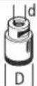
83--M14-900080

125 6 10 22,2 > 0 9000 80
Vernedeksel for slipping

natural_image
Mechanical diagram showing two cross-sectional views of a mechanical component with rotational arrows (no text or symbols)text_image
Technical diagram of a mechanical device with numbered components and directional arrow labeled ①text_image
Technical diagram of a mechanical device with numbered components and directional arrow labeled '↑0'Du kan løsne en uskadet hurtigspennmutter (21) som er riktig festet, for hånd. Da feller du opp bøylen til hurtigspennmutteren og dreier hurtigspennmutteren hardt mot urviseren. En hurtigspennmutter som sitter fast, må aldri løsnes med et verktøy. Bruk en tohullsnøkkel.
natural_image
Mechanical diagram showing two cross-sectional views of a mechanical component with rotational arrows (no text or symbols)text_image
Technical diagram of a mechanical device with numbered components and directional arrow indicating rotation or movement.text_image
Technical diagram of a mechanical device with numbered components and directional arrow labeled '1'natural_image
Diagram of two mechanical components with directional arrows indicating motion or force (no text or symbols)text_image
Technical diagram of a mechanical device with numbered components and directional arrow labeled ①text_image
Technical diagram of a mechanical device with numbered components and directional arrow labeled '↑0'natural_image
Diagram of two mechanical components with rotating arrows indicating motion (no text or symbols)text_image
Technical diagram of a mechanical device with numbered components and directional arrow indicating rotation or movement.text_image
Technical diagram of a mechanical device with numbered components and directional arrow labeled '1'text_image
maks. [mm] [mm] [°] D b s d σ [dev/ dak] [m/ sn]
text_image
maks. [mm] [mm] [°] D b s d a [dev/ [dk] [m/sn]
75 30 - M 14 - 9000 80

| 125 | 24 | - | M 14 | - | 9000 | 80 |
| 125 | 19 | - | 22,2 | - | 9000 | 80 |

125--M 14-900080
83--M 14-9000 80

125 6 10 22,2 > 0 9000 80
natural_image
Diagram of two mechanical components with rotating parts and directional arrows, no text or symbols presenttext_image
Technical diagram of a mechanical device with numbered components and directional arrow labeled '0'text_image
Technical diagram of a mechanical device with numbered components and directional arrow labeled 'o'natural_image
Mechanical diagram showing two cross-sectional views of a mechanical component with directional arrows (no text or symbols)text_image
Technical diagram of a mechanical device with numbered components and directional arrow indicating rotation or movement.text_image
Technical diagram of a mechanical device with numbered components and directional arrow labeled '0'text_image
max. [mm] [mm] [°] D b s d a [ot/ min] [m/s]
125 7,2 - 22,2 - 9 000 80

125 4,2 - 22,2 - 9 000 80
| max. [mm] [mm] [°] | ||||||
| D b s d a [ot/ | min) | [m/s] | ||||
 | 125 - - - - 9 000 80 | |||||
 | 75 30 - M 14 - 9 000 80 | |||||
 | 125 | 24 | - | M 14 | - | 9 000 80 |
| 125 | 19 | - | 22,2 | - | 9 000 80 | |
 | 125 - - M 14 - 9 000 80 | |||||
 | 83 - - M 14 - 9 000 80 | |||||
 | 125 6 10 22,2 > 0 9 000 80 | |||||
natural_image
Mechanical diagram showing two cross-sectional views of a mechanical component with rotational arrows (no text or symbols)text_image
Technical diagram of a mechanical device with numbered components and directional arrow indicating rotation or movement.text_image
Technical diagram of a mechanical device with numbered components and directional arrow indicating motion or assembly.text_image
max. [mm] [mm] [°] D b s d a [ot/ min] [m/s]
125 7,2 - 22,2 - 9 000 80

125 4,2 - 22,2 - 9 000 80

125 - - - - 9 000 80

75 30 - M14 - 9 000 80

125 24 - M14 - 9000 80 125 19 - 22,2 - 9000 80

125--M14-900080
83--M14-900080

125 6 10 22,2 > 0 9 000 80
natural_image
Diagram of two mechanical components with rotating arrows indicating motion (no text or symbols)text_image
Technical diagram of a mechanical device with numbered components and directional arrow labeled 'O'text_image
Technical diagram of a mechanical device with numbered components and directional arrow labeled 'O'natural_image
Diagram of two mechanical components with directional arrows indicating motion or force (no text or symbols)text_image
Technical diagram of a mechanical device with numbered components and directional arrow indicating rotation or movement.text_image
Technical diagram of a mechanical device with numbered components and directional arrow labeled ①natural_image
Diagram of two mechanical components with directional arrows indicating motion or force (no text or symbols)text_image
Technical diagram of a mechanical device with numbered components and directional arrow indicating rotation or movement.text_image
Technical diagram of a mechanical device with numbered components and directional arrow labeled '1'natural_image
Mechanical diagram showing two cross-sectional views of a gear or cam mechanism with rotational arrows (no text or labels)text_image
Technical diagram of a mechanical device with numbered components and directional arrows indicating motion or assembly.text_image
Technical diagram of a mechanical device with numbered components and directional arrow labeled '↑0'natural_image
Mechanical diagram showing two cross-sectional views of a mechanical component with directional arrows (no text or symbols)text_image
Technical diagram of a mechanical device with numbered components and directional arrow labeled '0'text_image
Technical diagram of a mechanical device with numbered components and directional arrow labeled 'o'natural_image
Diagram of two mechanical components with directional arrows indicating motion or force (no text or symbols)text_image
Technical diagram of a mechanical device with numbered components and directional arrow labeled '0'text_image
Technical diagram of a mechanical device with numbered components and directional arrow labeled 'O'natural_image
Diagram of two mechanical components with rotating arrows, no text or symbols presenttext_image
Technical diagram of a mechanical device with numbered components and directional arrow labeled 'O'text_image
Technical diagram of a mechanical device with numbered components and directional arrow labeled 'O'natural_image
Diagram of two mechanical components with rotating arrows indicating motion (no text or symbols)text_image
Technical diagram of a mechanical device with numbered components and directional arrow labeled '0'text_image
Technical diagram of a mechanical device with numbered components and directional arrow labeled 'O'Ugaona brusilica GWS18V-11PS
GAL 12V/18...
GAX 18...
EXAL18...
A) Nominalni broj obrtaja u praznom hodu u skladu sa EN IEC 62841-2-3 za izbor odgovarajućeg namenskog alata. Stvarni broj obrtaja u praznom hodu je iz sigurnosnih razloga i usled tolerancije tokom proizvodnje manji.
B) Sa dodatnom drškom (10), zaštitnim poklopcem za sečenje (13), prihvatnom prirubnicom (15), brzosteznom navrtkom (21), bez akumulatora (težinu akumulatora možete pogledati na www.bosch-professional.com)
C) ograničeni učinak na temperaturama < 0 °C
natural_image
Mechanical diagram showing two cross-sectional views of a mechanical component with rotational arrows (no text or symbols)Postavite zaštitnu haubu (12) na prihvatnik na električnom alatu, sve dok se grebeni za kodiranje zaštitne haube ne poklope sa prihvatnim delom. Pri tom pritisnite i držite tako ručicu za deblokiranje (1).
Pritiskajte zaštitnu haubu (12) na vrat vretena sve dok traka zaštitne haube ne nalegne na prirubnicu električnog alata i okreće zaštitnu haubu dok čujno ne ulegne u ležište.
Prilagodite poziciju zaštitne haube (12) zahtevima radnog koraka. Pritisnite ručicu za deblokiranje (1) nagore i okrenite zaštitnu haubu (12) u željeni položaj.
▶ Podesite zaštitnu haubu (12) tako da sva grebena poluge za deblokadu (1) upadnu u odgovarajuće otvore zaštitne haube (12).
▶ Podesite zaštitnu haubu (12) tako, da se sprečava letenje varnica u pravcu radnika.
▶ U smeru okretanja pribora zaštitna hauba (12) sme se okretati samo uz aktiviranje poluge za deblokadu (1)! U suprotnom, električni alat ne sme nikako da se dalje koristi i mora se predati servisu.
Napomena: Kodni ispust na zaštitnoj haubi (12) osiguravaju da se može montirati samo zaštitna hauba koja odgovara električnom alatu.
Usisna hauba za brušenje
Za brušenje boja, lakova i plastike sa što manje prašine, zajedno sa lončastim diskom od tvrdog metala (16) možete da koristite zaštitnu haubu (11). Usisna hauba (11) nije prikladna za obradu metala.
Na usisnu haubu (11) možete da priključite kompatibilan usisivač kompanije Bosch. Postavite usisno crevo sa usisnim adapterom u predviđeni prihvatni deo usisne haube.
Zaštitna hauba za presecanje
▶ Za rezanje uvek koristite zaštitnu haubu za rezanje (13) ili zaštitnu haubu za brušenje (12) zajedno sa prekrivkom za rezanje (14).
Prilikom presecanja u kamenu morate se pobrinuti za dovoljno usisavanja prašine.
text_image
Technical diagram of a mechanical device with numbered components and directional arrows indicating motion or assembly.text_image
Technical diagram of a mechanical device with numbered components and directional arrow labeled ①a_h,AG/CO = 5,2 m/s^2 (K = 1,5 m/s^2)
p_F,AG/CO = 136,7 ~m / s^2 (K = 4,5 ~m / s^2)
Brušenje z brusnim listom:
a_n,DS = 2,0m / s^2 (K = 1,5m / s^2)
p_F,DS = 60,9 ~m / s^2 (K = 4,9 ~m / s^2)
natural_image
Mechanical diagram showing two cross-sectional views of a mechanical component with rotational arrows (no text or labels)text_image
Technical diagram of a mechanical device with numbered components and directional arrow labeled ①text_image
Technical diagram of a mechanical device with numbered components and directional arrow labeled '1'natural_image
Diagram of two mechanical components with directional arrows indicating motion or flow (no text or symbols)Stavite štitnik (12) na prihvat na električnom alatu tako da se kodirni izdanci na štitniku podudaraju s prihvatom. Pritisnite i pritom držite polugu za deblokiranje (1). Pritišćite štitnik (12) na grlo vretena sve dok naslon štitnika ne sjedne na prirubnicu električnog alata i okrećite štitnik sve dok se čujno ne uglavi. Prilagodite položaj štitnika (12) zahtjevima faze rada. U tu svrhu pritisnite polugu za deblokiranje (1) prema gore i okrenite štitnik (12) u željeni položaj.
- Namjestite štitnik (12) uvijek tako da se oba utora na poluzi za deblokiranje (1) uglave u odgovarajuće otvore na štitniku (12).
▶ Štitnik (12) namjestite tako da se spriječi iskrenje u smjeru osobe koja radi s kutnom brusilicom.
text_image
Technical diagram of a mechanical device with numbered components and directional arrow indicating rotation or movement.Pritisnite tipku za blokadu vretena (2) kako biste fiksirali brusno vreteno. Za stezanje brzostezne matice (21) otklopite držač brzostezne matice i okrenite brzosteznu maticu snažno u smjeru kazaljke na satu. Zatim preklopite držač za fiksiranje brzostezne matice prema dolje. Pritezanje na rubu ploče nije dovoljno.
text_image
Technical diagram of a mechanical device with numbered components and directional arrow labeled 'O'Pravilno pričvršćenu, neoštećenu brzosteznu maticu (21) možete ručno otpustiti. U tu svrhu otklopite držač brzostezne matice i okrenite brzosteznu maticu snažno u smjeru suprotnom od kazaljke na satu. Brzosteznu maticu s čvrstim dosjedom nikada ne otpuštajte alatom, nego upotrijebite dvostruki okasti ključ.
340 | Hrvatski
Nakon montiranja prihvatne prirubnice i brusne/rezne ploče slobodna dužina navoja brusnog vretena mora iznositi najmanje 4 mm. Pazite na čvrst dosjed brusnog alata kako se ne bi odvrnuo od vretena
natural_image
Diagram of two mechanical components with directional arrows indicating motion or force (no text or symbols)text_image
Technical diagram of a mechanical device with numbered components and directional arrow indicating rotation or movement.text_image
Technical diagram of a mechanical device with numbered components and directional arrow labeled '1'natural_image
Mechanical diagram showing two cross-sectional views of a mechanical component with rotational arrows (no text or symbols)text_image
Technical diagram of a mechanical device with numbered components and directional arrow labeled ①text_image
Technical diagram of a mechanical device with numbered components and directional arrow labeled '1'natural_image
Mechanical diagram showing two cross-sectional views of a gear or cam mechanism with rotational arrows (no text or labels)text_image
Technical diagram of a mechanical device with numbered components and directional arrows indicating motion or assembly.text_image
Diagram of a mechanical device with numbered components and directional arrow labeled '0'natural_image
Mechanical diagram showing two cross-sectional views of a mechanical component with rotational arrows (no text or symbols)بوProduct.
text_image
Technical diagram of a mechanical device with numbered components and directional arrow indicating rotation or movement.natural_image
Diagram of two mechanical components with rotating parts and directional arrows, no text or symbols present| LED | |
| 3% 100-60 | |
| 2% 60-30 | |
| 30-5 | |
| 5-0 | |
| 5% 100-80 | |
| 4% 80-60 | |
| 3% 60-40 | |
| 2% 40-20 | |
| 1% 20-5 | |
| 1% 5-0 |
text_image
Technical diagram of a mechanical component with numbered parts and directional arrow labeled ①text_image
Technical diagram of a mechanical device with numbered components and directional arrows indicating motion or assembly.natural_image
3D rendered mechanical component with gear and shaft assembly (no text or symbols)2 608 000 882
∅ 115/125 mm
2 608 000 883
natural_image
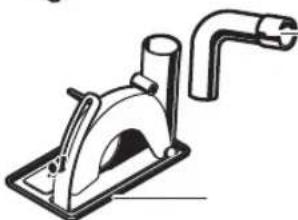
Technical line drawing of a mechanical device with a pipe and base plate (no text or symbols)2 605 510 264∅ 115/125 mm
406
natural_image
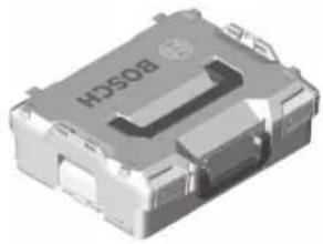
3D rendering of a metallic electronic component with visible internal structure and mounting holes (no text or symbols)L-BOXX 136
1 600 A01 2G0
natural_image
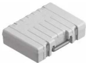
White plastic electronic component with metallic contacts and ridged top surface (no visible text or symbols)6 082 762 1KG
Legal Information and Licenses
Copyright © 2015, Infineon Technologies AG
All rights reserved.
Redistribution and use in source and binary forms, with or without modification, are permitted provided that the following conditions are met:
- Redistributions of source code must retain the above copyright notice, this list of conditions and the following disclaimer.
- Redistributions in binary form must reproduce the above copyright notice, this list of conditions and the following disclaimer in the documentation and/or other materials provided with the distribution.
- Neither the name of the copyright holders nor the names of its contributors may be used to endorse or promote products derived from this software without specific prior written permission.
THIS SOFTWARE IS PROVIDED BY THE COPYRIGHT HOLDERS AND CONTRIBUTORS "AS IS" AND ANY EXPRESS OR IMPLIED WARRANTIES, INCLUDING, BUT NOT LIMITED TO, THE IMPLIED WARRANTIES OF MERCHANTABILITY AND FITNESS FOR A PARTICULAR PURPOSE ARE DISCLAIMED. IN NO EVENT SHALL THE COPYRIGHT OWNER OR CONTRIBUTORS BE LIABLE FOR ANY DIRECT, INDIRECT, INCIDENTAL, SPECIAL, EXEMPLARY, OR CONSEQUENTIAL DAMAGES (INCLUDING, BUT NOT LIMITED TO, PROCUREMENT OF SUBSTITUTE GOODS OR SERVICES; LOSS OF USE, DATA, OR PROFITS; OR BUSINESS INTERRUPTION) HOWEVER CAUSED AND ON ANY THEORY OF LIABILITY, WHETHER IN CONTRACT, STRICT LIABILITY, OR TORT (INCLUDING NEGLIGENCE OR OTHERWISE) ARISING IN ANY WAY OUT OF THE USE OF THIS SOFTWARE, EVEN IF ADVISED OF THE POSSIBILITY OF SUCH DAMAGE.
Warranty Disclaimer
This product contains Open Source Software components which underly Open Source Software Licenses. Please note that Open Source Licenses contain disclaimer clauses. The text of the Open Source Licenses that apply are included in this manual under "Legal Information and Licenses".
408 | Legal Information and Licenses
Servicekontakte
Service Contacts
Contacts de Service
https://www.bosch-pt.com/serviceaddresses
Garantiebedingungen Guarantee Conditions Conditions de Garantie Condiciones de Garantía

text_image
QR code image containing encoded data, no visible human-readable texthttps://www.bosch-pt.com/guarantee/202507