
HG02730 - Scaffolding POWERFIX - Free user manual and instructions
Find the device manual for free HG02730 POWERFIX in PDF.

| Product type | Height-adjustable trestle |
| Brand | Powerfix |
| Model | HG02730 |
| Category | Workshop trestle |
| Maximum load capacity | 200 kg |
| Working height | 800 to 1300 mm |
| Weight | 6.26 kg |
| Main material | Steel |
| Intended use | Domestic, support for workpieces |
| Number of trestles needed | 2 (for a workbench) |
| Included parts | Round head screws (8x), hexagon socket screws (6x), washers, nuts, side parts (2), spacers (lower, support, central), hole rows (2), safety pins (2), anti-spreading guards (2), safety supports (2) |
| Safety | Safety pins, anti-spreading guards, safety supports |
| Height adjustment | By safety pin on hole row |
| Assembly | Assembly required, progressive tightening |
| Cleaning | Dry lint-free cloth, without aggressive products |
| Storage | Dry and closed room, legs folded |
| Disposal | Packaging recyclable, product via waste disposal center |
| Warranty | Not specified, contact manufacturer |
Frequently Asked Questions - HG02730 POWERFIX
User questions about HG02730 POWERFIX
0 question about this device. Answer the ones you know or ask your own.
Ask a new question about this device
Download the instructions for your Scaffolding in PDF format for free! Find your manual HG02730 - POWERFIX and take your electronic device back in hand. On this page are published all the documents necessary for the use of your device. HG02730 by POWERFIX.
USER MANUAL HG02730 POWERFIX
TELESCOPIC TRESTLE
GB IE NI
TELESCOPICTRESTLE
Assembly, operating and safety instructions
DK
H∅JDEJUSTERBARARBEJDSBUK
natural_image
Three-step mechanical assembly diagram showing bracket assembly with bolts, hooks, and chains (no text or symbols)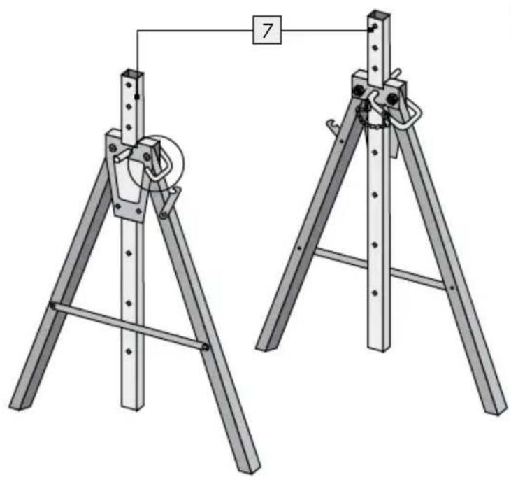
natural_image
Technical illustration of two mechanical lifting devices with a numbered connection point (7), no text or symbols present.Introduction......Page 6
Intended use....Page 6
Parts description an scope of delivery....Page 6
Technical data....Page 6
Safety instructions......Page 7
Installation Page 8
Use Page 8
Height adjustment Page 9
We congratulate you on the purchase of your new product. You have chosen a high quality product. Familiarise yourself with the product before using it for the first time. In addition, please carefully refer to the operating instructions and the safety advice below. Only use the product as instructed and only for the indicated field of application. Keep these instructions in a safe place. If you pass the product on to anyone else, please ensure that you also pass on all the documentation with it.
Intendeduse
The product is intended for use as a working bench trestle for home use. Other uses or changes to the product are considered to be contrary to the intended use and may harbour risks of injury and damage. The manufacturer does not accept any liability for injury or damage resulting from use of this product contrary to its intended use. The product is not intended to be used for commercial purposes.
● Parts description an scope of delivery
1 2 x Flat head bolt, incl. 2 washers, nut, ∅ 5 x 12 mm
2 x Hex head bolt, incl. washer, nut ∅ 5 x 12 mm
3 8 x Round head bolt, incl. 2 washers, nut ∅ 6 x 35 mm
4 4 x Hex head bolt, incl. washer, nut ∅ 8 x 45 mm
5 2 x Side frame
6 2 x Bottom plate
7 2 x Hole bar
8 1 x Top support bar
9 1 x Middle support bar
10 2 x Locking pin
11 Locking hook, short
12 Locking hook, long
13 Safety bracket
Operating instructions
- Technical data
Load Capacity: max. 200 kg
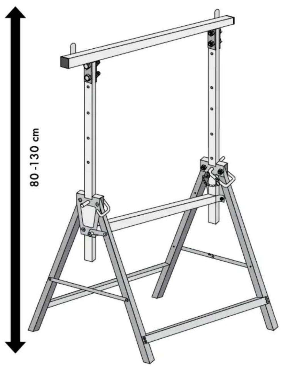
Working height: approx. 800-1300 mm
Net weight: approx. 6.26 kg

Safety instructions
KEEP ALL SAFETY NOTICES AND INSTRUCTIONS IN A SAFE LOCATION!
DANGYORLOSS OF LIFE AND ACCI-

DENT TO INFANTS AND CHILDREN! Never leave children unsupervised with the packaging materials. The packaging material presents a suffocation risk. Children frequently underestimate danger. Keep out of reach of children. This product is not a toy.
On delivery and prior to first use, inspect the product in order to check the condition and function of all parts. Do not use the product if it has been damaged. You risk injury if you do otherwise.
■ Do not use a damaged product.
CAUTION! Do not leave children unattended. The product is not a climbing frame or toy. Make sure that nobody climbs or leans on the product, particularly children. The product could become imbalanced and tip up. This may result in injury and/or damage.

CAUTION! RISK OF INJURY! Never use the product as a ladder or as anything else.

CAUTION! RISK OF INJURY! Never climb on the product or work surface.

Make sure that you never exceed the maximum permissible load (see "Technical data").

Make sure that the product is stable and cannot tip. Injuries or damage to the product can result.
CAUTION! CRUSHING HAZARD! Watch your fingers when opening and closing the product.
Only use the product on firm, level surfaces. If used on unstable or uneven surfaces- e.g. gravel surfaces- the load can slip.
■CAUTION! RISK OF INJURY! Absolutely do not use the prod-

uct on subsurfaces that have slopes. The product, along with any workpieces on it, can tip over.

sure the legs are folded apart all the way and the locking hooks 11 12 are secured in place when using the product. This will ensure stability.

continue using the product if the leg lock, adjustment or the weld are damaged.

CAUTION! RISK OF INJURY! Make sure that the subsurface is not damp or oily. The product can slip and fall over.
Verify the work pieces/sheet will not move on the top support bar 8. If necessary, secure in place.
■ Make sure that you do not load workpieces unevenly. Otherwise, the workpiece can become unbalanced and fall down.
■ Remove any excess materials on the product, e.g. wet paint, dirt, oil or snow.
- Installation
Note: To begin the assembly, please be reminded to only tighten all screw connection slightly, and only tighten fully the screw connection when the product is assembled completely.
First spread the leg of side frame. Pull down the locking pin 10 on the leg and lock the locking hook 12 on the other leg. Insert the hole bar 7 through the middle part of side frame 5. Use the locking pin 10 and insert through the hole on the side frame 5 in order to lock the hole bar 7 in place. Please be reminded to leave at least 3 holes to be protrude on top of the frame. Repeat the above steps to have 2 side frames with support bar (Fig. A).
Make sure both hole bars are on the same height.
Connect the middle support bar and use screw sets 1 and 2 to connect with both side frames 5 (Fig. B).
Use screw set on the side where is the locking hook 11 on the leg. After you finish connect screw set 2, pull down the locking hook 11 and lock the hooks on the screw. Use the screw sets 1 on the other side. Repeat the above steps to fix the middle support bar 9 in place (Fig. C).
Connect the bottom plate to the leg with screw set 3. Repeat the above to fix both bottom plates in place (Fig. D).
Place the top support bar onto the hole bar 7. Use screw sets 4 to fix the top support bar 8 in place (Fig. E).
□ Align the product and tighten all the screw connections
☐ Raise the two safety bracket 13 on the top support bar 8 (Fig. F).
- Use
CAUTION! RISK OF INJURY! Be sure locking hooks ^11 und ^12 are secured in place. The two trestles must be set to the same working height. This will ensure stability.
☐ Verify the work pieces/sheet will not move on the top. If necessary, secure in place.
Make sure that you do not load workpieces unevenly. Otherwise, the workpiece can become unbalanced and fall down.
□ Always use two trestles and a board or boards together for working.
☐ Fold the legs all the way apart.
☐ Verify the safety devices and adjustments are positioned correctly.
Place the work piece you will be working on on the top support bar.
● Height adjustment
The locking pins 10 are used to adjust the product height.
Remove all workpieces/the working board from the product.
Take out the locking p10. Adjust the hole bar 7 on both side to the desired working height.
☐ Insert the locking pin to lock the hole bar 7 in place.
- Cleaning und care
□ Clean the product with a dry, fluff-free cloth.
☐ Never use aggressive or corrosive cleaning agents, as they may damage the product.
●Storage
☐ Having finished the work, unhook the two locking hock and fold the legs together.
Store the product in a dry place if you are not going to use it for a protracted period.
●Disposal

The packaging is made entirely of recyclable materials, which you may dispose of at local recycling facilities.
Contact your local refuse disposal authority for more details of how to dispose of your worn-out product.
Indledning ......Side 11
natural_image
Technical line drawing of a mechanical ladder assembly with a pulley and numbered component (no text or symbols)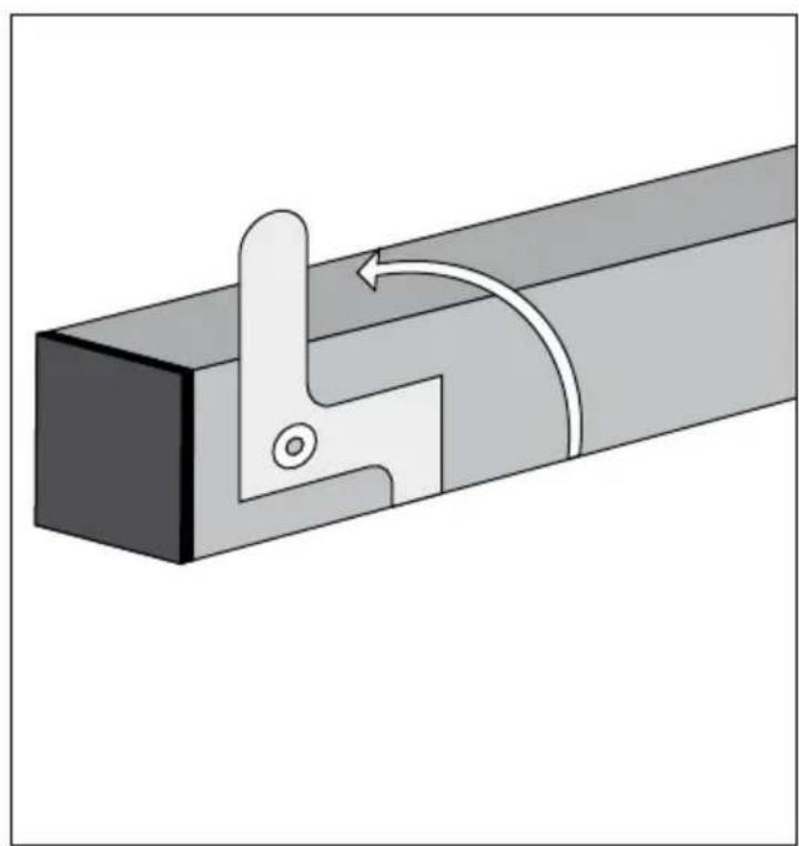
natural_image
Mechanical assembly diagram showing a lever mechanism with a curved arrow indicating rotation (no text or symbols present)
natural_image
Technical line drawing of a metal frame structure with a 80-130 cm height dimension label (no text or symbols on the diagram itself)OWIM GmbH & Co. KG
Stiftsbergstraße 1
DE-74167 Neckarsulm
GERMANY
Model-No.: HG02730
Version: 07/2017
Last Information Update · Tilstand af
- TELESCOPIC TRESTLE
- TELESCOPICTRESTLE
- H∅JDEJUSTERBARARBEJDSBUK
- Introduction......Page 6
- Safety instructions......Page 7
- Installation Page 8
- Intendeduse
- ● Parts description an scope of delivery
- - Technical data
- Safety instructions
- KEEP ALL SAFETY NOTICES AND INSTRUCTIONS IN A SAFE LOCATION!
- DANGYORLOSS OF LIFE AND ACCI-
- - Installation
- - Use
- ● Height adjustment
- - Cleaning und care
- ●Storage
- ●Disposal
- Indledning ......Side 11
Brand : POWERFIX
Model : HG02730
Category : Scaffolding