
SRC065 - Ice Maker Scotsman - Free user manual and instructions
Find the device manual for free SRC065 Scotsman in PDF.


| Product Type | Domestic Ice Machine |
| Brand | Scotsman |
| Model | SRC065 |
| Refrigerant | R290 (flammable) |
| Supply Voltage | 115 V, 15 A (dedicated circuit) |
| Dimensions (W x D x H) | 38 cm x 58 cm x 85-87 cm (handle +4.1 cm) |
| Production Capacity | 24 ice cubes per cycle |
| Ambient Temperature | Min 10 °C, max 38 °C |
| Water Temperature | Min 4.5 °C, max 38 °C |
| Water Pressure | Min 1.4 bar, max 5.5 bar |
| Available Types | Pump (SRCP065A) or Gravity (SRCG065A) |
| Front Panel Material | Stainless steel |
| Control Panel | Indicators: MAKING ICE, CHECK WATER, TIME TO CLEAN, RESET CLEAN |
| Maintenance | Condenser cleaning, descaling, disinfection |
| Safety | Automatic stop when bin full, backflow protection, flammable refrigerant |
| Warranty | Coverage of material and workmanship defects (excluding installation errors) |
| Reversible Door Swing | Yes, left or right side |
| Ice Cube Type | Tapered cylindrical |
| Dedicated Electrical Circuit | Required, no extension cord |
Frequently Asked Questions - SRC065 Scotsman
User questions about SRC065 Scotsman
0 question about this device. Answer the ones you know or ask your own.
Ask a new question about this device
Download the instructions for your Ice Maker in PDF format for free! Find your manual SRC065 - Scotsman and take your electronic device back in hand. On this page are published all the documents necessary for the use of your device. SRC065 by Scotsman.
USER MANUAL SRC065 Scotsman
Installation and User's Manual for Residential Ice Machine
Model SRC065
natural_image
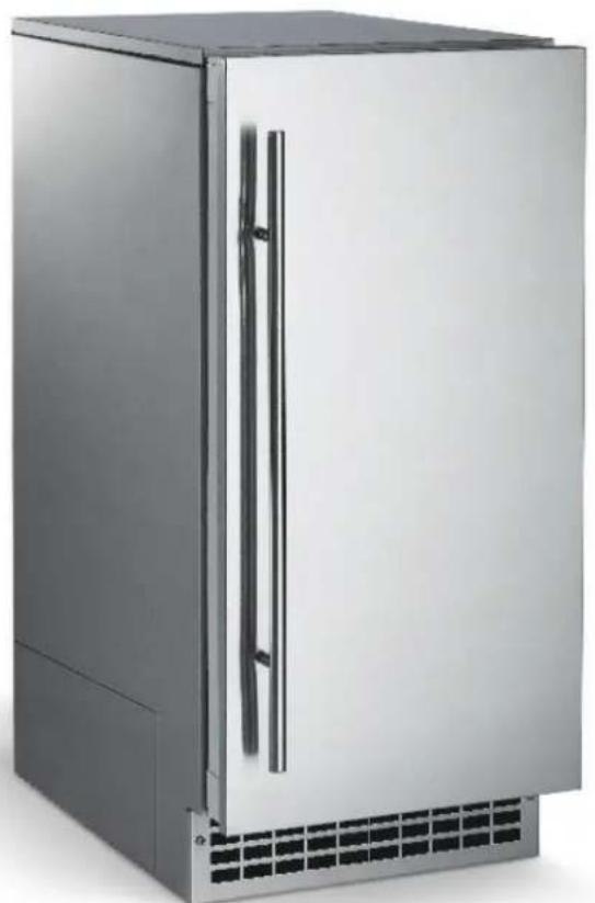
Exterior view of a stainless steel refrigerator with ventilation grilles and cooling fins (no text or symbols visible)Brilliance™
Safety Information
Important Safety Information. Make sure to read through fully to avoid severe injury or death.

WARNING
R290 Refrigerant is
Flammable.
Flame can cause burns or property damage
Keep away from sources of fire
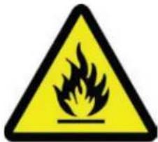

This ice machine contains FLAMMABLE refrigerant and improper use can result in fire or explosion. Do not use cigarettes, vapes, or cellphones near pipes or cables, as it can be a source of ignition or spark.

This ice machine must not be installed next to equipment with an open ignition source (ie. open flames, an operating gas appliance, or electric heater). Do not store explosive substances such as aerosol cans with a flammable propellant in this appliance.

WARNING: Do not use electrical appliances inside the food/ice storage compartments unless they are of the type recommended by the manufacturer.

WARNING: In order to reduce flammability hazards the installation of this appliance must only be carried out by a suitably qualified person.

This appliance must be installed according to the safety standard for refrigeration systems presented in ANSI/ASHRAE 15.

Do not install next to anything that continuously vibrates, avoiding excessive vibrations or pulsations.

Install in a well ventilated environment and ensure ventilation and outlets are not obstructed.

Properly secure electrical wiring and cabling for the machine to minimize wear and vibrations.

Keep fire extinguisher nearby in case of emergencies.

WARNING: Do not damage the refrigerating circuit

Use a Scotsman recommended technician certified to repair R290 equipment.

Install ONLY Scotsman factory service parts. Use of non-OEM parts can be dangerous due to the design changes needed to safely use R290 refrigerant.

WARNING: Cancer and Reproductive Harm. Visit www.P65Warnings.ca.gov for details.

This appliance is not intended for use by persons (including children) with reduced physical, sensory or mental capabilities, or lack of experience and knowledge, unless they have been given supervision or instruction concerning the use of the appliance by a person responsible for their safety.

Children should be supervised to ensure that they do not play with the appliance.
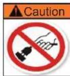
Do not unplug or disconnect power to the ice machine with out shutting off the water supply.
Note: This ice machine should be on its own dedicated circuit with out any other appliances or devices.
SRC065
Installation and User's Manual
Introduction:
This ice machine is the result of Scotsman's decades of experience as an industry leader in the design and manufacture of both commercial and residential ice machines.
This manual includes the information needed to install, start up and maintain the ice machine. Note any Caution or Warning indicators, as they provide notice of potential hazards. Keep this manual for future reference.
Table of Contents
Specifications 2
Air flow....3
Cabinet Drawing....4
Water Quality 5
Door Swing Change 6
Installation: Water & Drain....7
Installation: Gravity Drain 8
Installation: Electrical....9
Use....10
Maintenance....11
Cleaning the Condenser and Winterizing....12
Removing Scale from the Ice Making System 13
What to do before calling for service....14
Decommissioning 15
Outdoor Use Notice:
Keep from Freezing: Severe damage will occur to the unit if left in or operated in temperatures beyond the limits listed in this manual. That damage is NOT covered by warranty.
Keep Dry: Do not locate in low lying areas where puddles will accumulate.
Provide Shade: Heat gain from the sun will reduce the unit's ability to make and store ice, and ultraviolet radiation from the sun can potentially damage the unit's plastic components.
Water Supply: Avoid a long run of hose or tubing exposed to the sun. Plastic water supply tubing should be rated for potable water and include UV protection. Copper tubing is recommended.
Back Flow Prevention: The unit includes back flow prevention. No additional check valve is required.
Drainage: Do not drain into swimming pool or onto grounds.
Operation: It is normal for the ice level in the storage bin to be low when unit is used in temperatures below 65^ F.
Specifications
This ice machine is designed to be used indoors in a controlled environment, or outdoors within certain limits. It can be used in a wide variety of environmental conditions, but there are limits. Use outside of the listed limitations is misuse and will void the warranty.
Air temperature limits:
The ice machine will operate adequately within the limits, but functions best in temperatures between 70 - 80°F.
• Minimum: 50°F (10°C)
• Maximum: 100°F (38°C)
Water temperature limits:
• Minimum: 40^ F ( 4.5^ C)
• Maximum: 100°F (38°C)
Water pressure limits:
• Minimum: 20 psi (1.4 bar)
• Maximum: 80 psi (5.5 bar)
Because the ice machine is making a food product, the water supply to the ice machine must be potable, or fit for human consumption.
Electrical voltage limits:
• Minimum: 104 volts
• Maximum: 126 volts
Models:
There are four air cooled models:
- SRCP065A-1SS: Pump model, stainless front
- SRCP065A-1SU: Pump model, unfinished front
- SRCG065A-1SS: Gravity drain model, stainless front
- SRCG065A-1SU: Gravity drain model, unfinished front
Dimensions
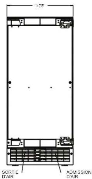
| Width Depth, handle | adds 1 5/8" Height | |
| 14 7/8" 22 3/4" 33 3/8" to 34 3/8" | ||

SRC065
Installation and User's Manual
Air flow
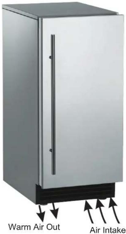
The machine takes in room temperature air at the lower right front and forces warm air out the lower left front. Restricting the airflow or operating the machine in a hot or cold environment will adversely affect the ability of the ice machine to make ice.
When the door is opened, the control panel, ice making area and ice storage bin are visible. The scoop is located in a holder along the right side wall.
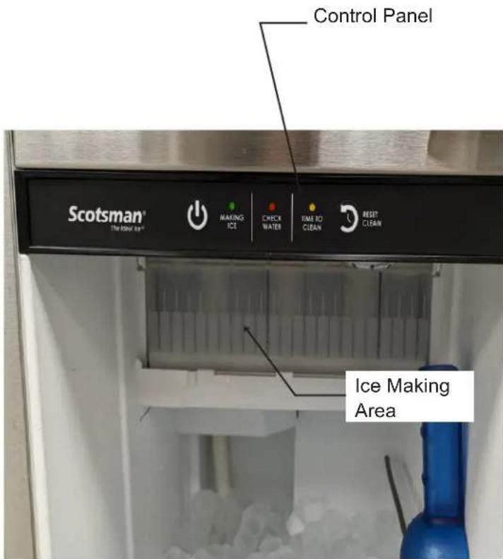
Scotsman Ice Systems are designed and manufactured with the highest regard for safety and performance. They meet or exceed the standards of UL60335-2-24.
Scotsman assumes no liability or responsibility of any kind for products manufactured by Scotsman that have been altered in any way, including the use of any parts and/or other components not specifically approved by Scotsman.
Scotsman reserves the right to make design changes and/or improvements at any time.
Specifications and designs are subject to change without notice.
Cabinet Drawing
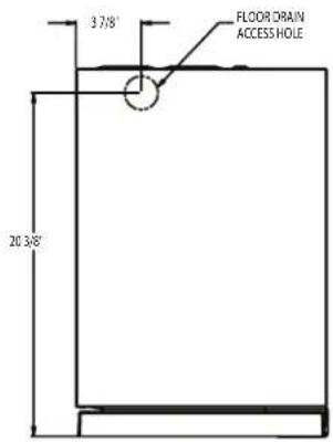
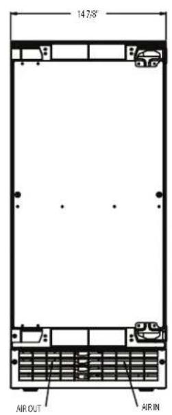
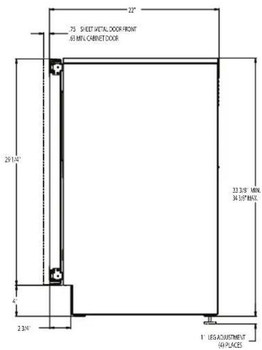
Installation Notes
Built in Situations: If a finished floor is to be installed in the area after the ice machine has been built in, shims the expected thickness of the floor should be installed under the unit to keep the machine level with the planned floor level.
Installations on a Slab: Use a pump model and pump the water to the point of drainage. Pump models will pump 1 story (10 feet) high.
Installations Over a Crawl Space or Basement: Either gravity drain or pump model units may be used. If there is not enough room behind the machine for a drain/waste receptacle, the drain will have to be below the floor.
Note: When installed in a corner, the door swing may be limited due to handle contact with the wall or cabinet face.
Water Quality
All water, including potable water supplied by municipalities, contains some impurities or minerals. Water absorbs impurities from the air as rain and/or as it flows through the ground. Some of the impurities are solid particles. These are known as suspended solids, and a fine particle filter will remove them. Other impurities are chemically bonded to the water molecules, and cannot be filtered out. These are called dissolved solids.
Ice made by this machine will have a lower mineral content than the water it was made from. This is due to the method of making ice. Purer water will freeze first in the ice making molds. The reason for this is that anything dissolved in water lowers the water's freezing temperature. This concentrates most of the impurities in the ice machine water reservoir where they may form hard deposits known as scale. The machine dilutes the concentration of minerals by over-filling the reservoir during the harvest cycle (with the excess water flowing down the drain). Between 2 and 4 pints of water flow into the unit each cycle. Between 1 and 3.5 pints of that rinses the reservoir and goes down the drain.
Some impurities will inevitably remain, will stick to the parts in the machine, and will cause malformed ice cubes. Eventually, built up mineral scale can shorten machine life.
To keep the machine operating properly, these impurities or minerals will have to be regularly dissolved by an acid cleaning, using Scotsman Ice Machine Scale Remover. Directions for this can be found in the section under cleaning.
Filters and Treatment
In general, it is always a good idea to filter the water. A water filter, if it is of the proper type, can remove taste and odors as well as particles. Some methods of water treatment for dissolved solids include reverse osmosis and polyphosphate feeders.
RO Water
This machine can be supplied with Reverse Osmosis water, but the water conductivity must be no less than 10 microsiemens/cm. A reverse osmosis system should include post treatment to satisfy the RO water's potential aggressiveness. Deionized water is not recommended.
Because water softeners exchange one mineral for another, softened water may not improve water conditions when used with ice machines. Where water is very hard, softened water could result in white, mushy cubes that stick together.
If in doubt about your water quality or filtration needs, contact a local water specialist for recommendations on water treatment.
Installation Overview
The ice machine must:
- be connected to cold, potable water
- be connected to a drain
- be connected to the proper power supply
- be able circulate air through the vents at the front.
Note: Do not build in so that the door is recessed.
Door Swing Change
Note: Prior models had separate hinge brackets and different directions to change swing.
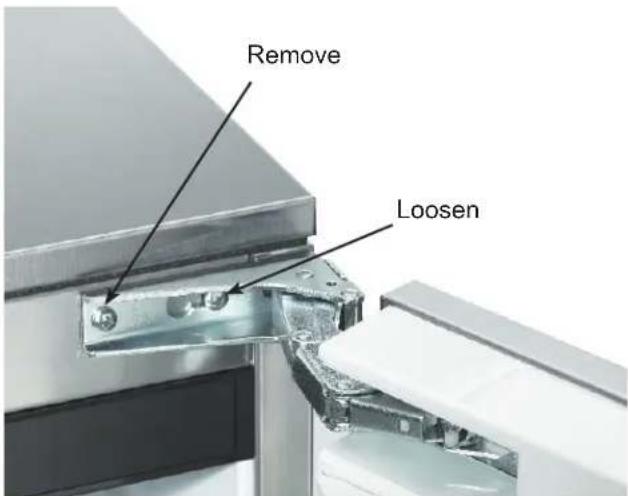
Moving the hinges allows the door to open from either the left or right side. Change swing before attaching door panel. To change:
- Remove innermost screw holding each hinge to cabinet, then loosen the outer screw.
- Slide door to the side and remove from cabinet.
-
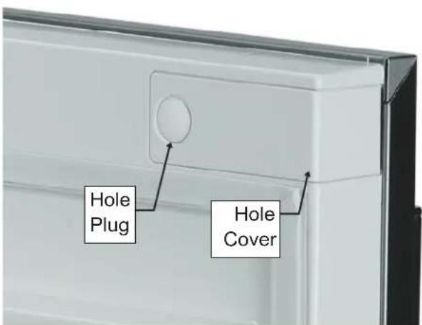
Remove plug and hinge pocket covers from door.
-
Remove hole plugs or screws from unit's new hinge locations, set aside.
- Move screws loosened in step 1 to opposite location.
- Install screws or plugs removed in step 4 to the unit's original hinge location to fill the holes.
- Remove the upper hinge from the door and move it to the door's opposite side, bottom location. Secure using the original screws.
Note: If door panel is attached, it must be removed to access hinge screws and to reverse handle position.
- Remove the original lower hinge and move it to the door's opposite side, upper location. Secure using the original screws.
- Install pocket covers and hole plugs onto door.
- Attach the door to the cabinet using the original screws.
Installation Notes
Built In Situations: If a finished floor is to be installed in the area after the ice machine has been built in, shims the expected thickness of the floor should be installed under the unit to keep the machine level with the planned floor level.
Installations On a Slab: Use a pump model and pump the water to the point of drainage. Pump models will pump 1 story (10 feet) high.
Installations Over a Crawl Space or Basement: Either gravity drain or pump model units may be used, if there is not enough room behind the machine for a drain/waste receptacle, the drain will have to be below the floor.
Note: When installed in a corner, the door swing may be limited due to handle contact with the wall or cabinet face.
Installation: Water & Drain
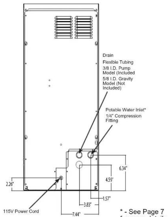
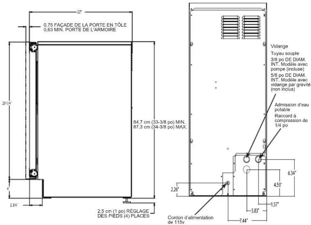
This model includes factory-installed water and drain lines. The installer must connect these lines to the building's water supply and drain system. All horizontal runs of drain lines must have a 14 " per foot fall. An air gap will likely be required between the ice machine drain tube and the drain/waste receptacle. Install an easily accessible shut-off valve between the supply and the unit. This shut-off valve should not be installed behind the unit.
Note: Do not use self-piercing type valves.
- Place ice machine in front of installation location. Adjust leg levelers to approximately correct position.
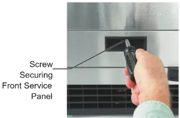
- Remove the front service panel.
- Locate the factory-installed water line at the rear of the cabinet. The line terminates with a compression fitting. Connect this fitting to the
building's cold water supply and tighten the compression nut to seal.
- Check all connections for leaks and water drips and ensure hoses are secure.
Drains
There are two types of ice machine models. One drains by gravity while the other uses an internal drain pump.
Drain Pump Model Drain Installation
-
- Locate the coil of factory-installed 3/8" ID plastic drain tubing secured to the back of the cabinet.
- Route the drain tubing from the back of the unit to the drain connection point.
- Pour water into ice bin to check for leaks.
IMPORTANT NOTE: Often an air gap is required by local codes between the ice maker drain tube and the drain receptacle.
CAUTION
Keep unit from Freezing
Note: It is recommended to purge the water supply lines prior to connecting to the ice machine. This will flush sediment from the line and prevent water flow restrictions.
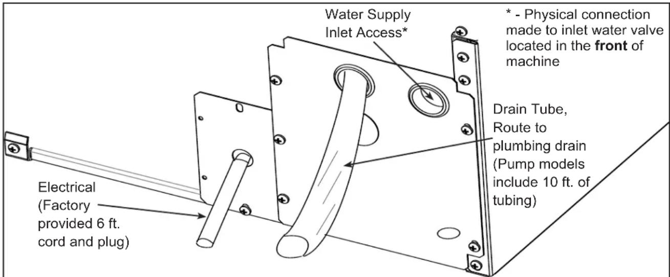
Back View, Drain Pump Model
September 2025
Installation: Gravity Drain
Caution: Restrictions in the drain system to the machine will cause water to back up into the ice storage bin and melt the ice. Gravity drain tubing must be vented, have no kinks and slope to the building drain. Air gaps are typically required by local code.
- Place the ice machine in front of the installation opening. Adjust leveling legs to the approximate height.
- Remove the front service access panel and the upper back panel.
Note: If you are connecting a gravity drain model and the drain opening has been located in the floor under the base pan according to the pre install specifications, follow steps 3 through 6 to drain the unit through the base. If not, proceed to step 6b.
- Remove the clamp and barbed elbow from the installed drain line and take off the plastic cover in the base pan below the drain hose.
- Connect a straight 5/8" barbed connector to the drain hose, securing with the supplied clamp removed in step 3.
- Cut an 8" piece from the drain line tubing. Slide one end of the tube onto the outlet of the barbed connector and secure with a clamp. Leave the other end of the tube lying on the
floor of the base pan until the unit is positioned over the floor drain.
- Route the drain tube. Either:
a) Insert the drain tube through the base pan into the floor drain.
or
b) Route the drain tube through the left hole in the lower back panel and connect to barbed elbow and secure with a clamp.
- Pour water into ice bin to check for leaks.
- Reinstall the upper back panel.
- Reinstall the service access panel. Level the unit.
Note: It is recommended to purge the water supply lines prior to connecting to the ice machine. This will flush sediment from the line and prevent water flow restrictions.
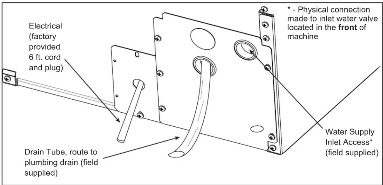
Back View, Gravity Drain Model
Installation: Electrical
The ice machine is supplied with a power cord. Do not remove the grounding pin from the cord's plug. Do not use extension cords. Follow all codes. Connect the machine to a dedicated 115 volt, 15 amp circuit.
- If the electrical outlet for the ice maker is behind the unit, plug in the unit.
- Position the unit in the installation opening.
- After the water supply has been purged, turn on the water supply. Make sure that the ice maker is plugged in and the power is on. Verify water leaks are not present.
- Slide unit into installation opening, paying careful attention to water supply and drain connections. Do not kink!
- Pour a couple of quarts of water into the ice storage bin. On drain pump equipped machines, the drain pump should start and water should pump out. Check for leak drips and ensure hoses are secure.
-
Replace the service access panel.
-
Level the unit as needed.
Note: The unit is equipped with an electrical power cord, but should only be plugged into a circuit dedicated to the ice machine. The unit must be the only device on the circuit and powered directly from the breaker panel.
Confirm the outlet is properly grounded and is in good condition. Worn outlets should be replaced as they can cause erratic operation of equipment. Do not use an extension cord.
Installation Checklist:
- Has the unit been connected to the proper water supply?
- Has the water supply been purged?
- Has the water supply be checked for leaks?
- Has the unit been connected to a drain?
- Has the drain been tested for flow and leaks?
- Has the unit been connected to the proper electrical supply?
- Has the unit been leveled?
- Have all packing materials been removed from the machine?
- Has the unit been plugged into a dedicated circuit?
Initial Start Up
- Turn on the water supply.
- Switch on the electrical power.
- Push and release the Power button to start the machine. The Ice Making light next to the Power button will glow green.
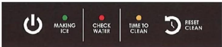
- Water will begin to flow into the unit. When the reservoir is full, water will start to drain from the machine. After a few minutes the compressor, water pump and fan motor will begin to operate and the first ice making cycle will begin.
No adjustments are needed.
After about a half hour, ice will fall into the ice storage bin. The machine makes 24 cubes per batch. It is normal for the first batches of ice to melt. That will continue until the bin has cooled. It will take 8 to 10 hours of continuous run time to fill the ice bin. When the bin is full of ice, the ice machine will shut off. It will automatically restart when the ice level falls, either from use or normal meltage.
Use
No special instructions are needed for use. Just take as much ice as you need and the machine will replace it. A scoop is provided and can be stored in the machine using the loop of tubing on the right side as a holder.
The machine can be shut off at anytime by pushing and releasing the Power button. The machine will shut off at the end of the next cycle. To shut off immediately, push and hold the Power button in until the machine stops.
What shouldn't be done?
Never keep anything in the ice storage bin that is not ice. Objects like wine or beer bottles are not only unsanitary, but the labels can slip off and plug up the drain.
Never allow the machine to operate without regular cleaning. The machine will last longer if it is kept clean. Regular cleaning should happen at least once per year, and preferably twice. Some water conditions will dictate even more frequent cleaning of the ice making section, and some carpets or pets will dictate more frequent cleaning of the condenser.
Note: The Time to Clean light will turn on after 6 months of power. It will remain on until the ice making system is cleaned using the process on page 13.
Noise:
The ice machine is designed for quiet operation, but will make some noise during the ice making cycle. During a freezing cycle, it is normal to hear the fan moving air and the water pump circulating water. Ice hitting the bin or ice in the bin can be heard during harvest.
natural_image
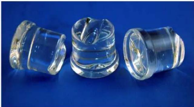
Three transparent glass cylindrical objects with internal cavities, displayed on a blue background (no text or symbols visible)Normal cubes are tapered cylinders. If the cubes are ragged and mis-shaped, mineral scale must be removed from the ice making system.
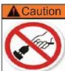
Do not unplug or disconnect power to the ice machine with out shutting off the water supply.
Note: This ice machine should be on its own dedicated circuit with out any other appliances or devices.
Maintenance
It is the User's responsibility to keep the ice machine and ice storage bin in a sanitary condition. Without human intervention, sanitation will not be maintained. Ice machines also require occasional cleaning of their water systems with a specifically designed chemical. This chemical dissolves mineral build up that forms during the ice making process.
6 Ice Machine Components to Keep Clean:
- The outside cabinet & door.
- The ice storage bin.
- The condenser.
- The ice making system.
- The ice scoop.
- The drain pump.
Cleaning the Ice Storage Bin.
The ice storage bin should be sanitized occasionally. It is usually convenient to sanitize the bin after the ice making system has been cleaned, and the storage bin is empty. A sanitizing solution can be made of 1 ounce of household bleach and two gallons of hot (95°F – 115°F) water. Use a clean cloth and wipe the interior of the ice storage bin with the sanitizing solution, pour some of the solution down the drain.
Allow to air dry.
Cleaning the Cabinet:
Wipe off any spills on the surface of the door and handle as they occur. If anything spilled on the door or gasket dries onto the surface, wash with soap and warm water to remove.
Over time biofilm can grow inside the drain system which can affect the ability for the drain system to evacuate the drain water. On the pump models this will result in the pump getting stuck on; and running dry. This leads to pump failure. Biofilm and pump cycling issues will eventually lead to low production and standing water in the bin. To ensure that this does not become an issue frequent bin sanitizing may be required.
Cleaning the Condenser and Winterizing
Condenser cleaning
The condenser is like the radiator on a car, it has fins and tubes that can become clogged with dirt and lint.
Note: Outdoor operation can lead to rapid build up of debris, such as leaves and other vegetation. The condenser will need to be frequently checked for debris. Clean it whenever the fins are obstructed.
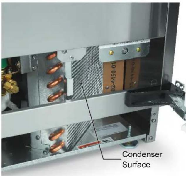
To clean:
- Remove the kickplate and front service panel.
- Locate the condenser surface.
- Vacuum the surface, removing all dust, dirt and lint.
CAUTION: DO NOT DENT THE FINS.
- Return the kickplate and front service panel to their original positions. Fasten them to the cabinet using the original screws.
Winterizing
- Clean the ice making system.
- Open the door, then push and release the Power button to turn the machine off.
- Turn off the water supply.
- Drain the water reservoir by removing the rubber plug under the reservoir. The plug is located near the back wall of the ice storage bin.
- Disconnect the incoming water line at the inlet water valve.
- Open the door, then push and release the Power button to turn the machine on.
- Blow air through the inlet water valve. A tire pump could do the job.
- Drain pump models should have about 1/2 gallon of RV antifreeze (propylene glycol) poured into the ice storage bin drain.
CAUTION: AUTOMOTIVE ANTIFREEZE MUST NOT BE USED.
- Power off and unplug the machine.
Caution
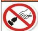
Do not unplug or disconnect power to the ice machine with out shutting off the water supply.
Note: This ice machine should be on its own dedicated circuit with out any other appliances or devices.
Removing Scale from the Ice Making System
- Scoop out all of the ice. Either discard the ice or save it in an ice chest or cooler.
- Press and HOLD the Power button in for 3 seconds until the Green light goes out.
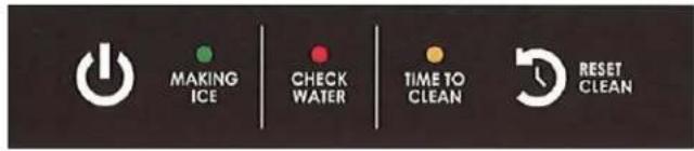
-
Press and HOLD both the Reset / Clean and Power buttons for 5 seconds. The Time to Clean light will blink on and off.
-
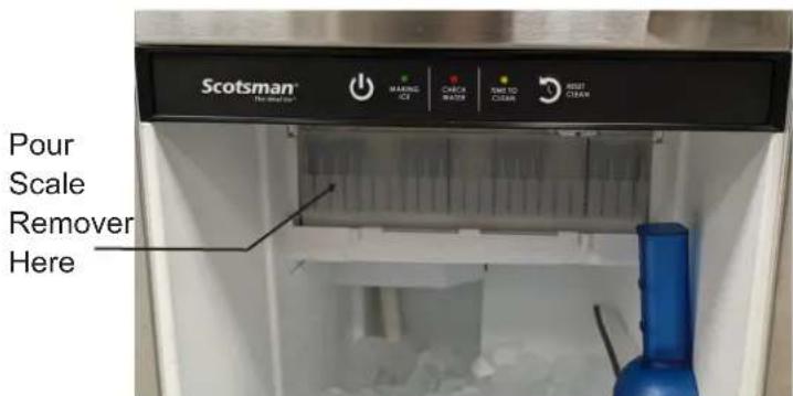
Pour 8 ounces of Scotsman Ice Machine Scale Remover (available from a local Scotsman Distributor or Dealer) into the ice machine reservoir.
-
Operate the machine for about 1/2 hour.
-
Push and release the Power button. The machine will begin to flush out the cleaning solution.
-
Operate the machine for another 1/2 hour.
-
Push and release the Power button. The machine will stop the cleaning process.
*For Pump Only models.
- Clean the bin liner of mineral scale by mixing a solution of 2.5 ounces of Clear 1 Scale Remover and 1 quart of water. Scrub the scale off of the liner.
*9a. Slowly pour 1 quart of water down the bin drain until the pump turns on. Once pump turns on IMMEDIATELY stop.
*9b. Once pump shuts off, add a mixture of 10 ounces of water and 4 ounces of Scotsman's Clear 1 scale remover to bin drain. If the pump cycles during this process, then repeat step 9a; making sure to stop pouring as soon as the pump turns on. Then repeat step 9b. Let machine sit in off state for 12 an hour.
- Rinse the liner with hot water.
Sanitize the bin interior.
\*For Pump Only models.
- Create a solution of sanitizer by mixing 1 gallon (4 liters) of clean, warm potable water (105-115°F) with 1.6 ounces of locally approved sanitizer to sanitize the bin interior and flush the drain.
*11a. Pour 1 quart of water down the bin drain until the pump turns on. Once pump turns on IMMEDIATELY stop.
*11b. Once the pump shuts off, mix 13 ounces of clean, warm potable water (105-115°F) with 1 ounce of locally approved sanitizer to sanitize the bin interior. If the pump cycles during this process, then repeat step 11a; making sure to stop pouring as soon as the pump turns on. Then repeat step 11b. Let machine sit in off state for 10 minutes.
-
Remove the top panel.
-
Pour 2 quarts of sanitizer solution onto the top of the ice making platen. Be sure all surfaces inside the platen are contacted by the sanitizer.
-
Return the top panel to its original position.
-
Remove the curtain and wash it with the sanitizing solution. Return the curtain to its original position.
What to do before calling for service
Sanitizing Continued:
- Press and HOLD the both the Clean-Reset and On/Off buttons for 5 seconds. The Time to Clean light will blink on and off.
- Thoroughly wash all surfaces of the reservoir, bin liner, scoop, scoop holder and door liner with the sanitizer solution. Pour excess solution into bin to sanitize the drain. Wait 10 minutes, push and release the On/Off switch. The machine will begin to flush out the sanitizing solution.
- Operate the machine for another 12 hour.
- Push and release the On/Off switch. The machine will stop the cleaning process.
- Rinse the liner with hot water.
- Push and release the On/Off switch again to restart ice making.
The ice scoop should be washed regularly, wash it just like any other food container.
What To Do Before Calling For Service
Ice cubes are incompletely formed
- Clean the ice making system
Low capacity
- Check for restricted drain or standing water in the bin
- Clean the air cooled condenser fins
No ice
- Check on-off switch
- Check electrical breaker
- If the Check Water light is flashing Red, check water supply. The control system checks for water every 20 minutes. When the water supply is restored, the machine will automatically restart ice making.
Time to Clean light is on
- Clean the ice making system.
Bin Thermostat
When the ice machine shuts off the ice level in the bin should be even with the metal tube inside the bin. If the ice in the bin is too high or low, turn the ice machine control to adjust the bin thermostat.
- To lower the ice level, turn the control counterclockwise. Usually a 1/8 turn will be enough.
- To increase the ice level, turn the control clockwise. Usually a 1/8 turn will be enough.
Decommissioning
Only qualified technicians familiar with R290 refrigerant should decommission a machine, as special tools and containers are required for the removal, transportation, and disposal of this highly flammable substance.
• Before attempting the procedure:
* Ensure that all protective gear is present and used throughout the procedure.
* Make sure recovery equipment and containers are available and ready for use. All containers used for recovery must be rated for R290 refrigerant and must be labeled as such.
* Weigh any refrigerant prior to reclaiming.
- Maintain safety through standard operating procedures as outlined on page 20 of this document. Be sure to follow local, state, and federal guidelines for proper disposal.
- Do not fill containers more than 80% and do not exceed the pressure limits of the container. Make sure the machine to be decommissioned is in satisfactory working order and that the electrical components of the machine are properly sealed to prevent ignition.
- Recovered refrigerant should not be charged into another refrigerating system or mixed in another container.
- Make sure to safely transport the refrigerant in line with standard operating procedures.
- All recovered refrigerant must be returned to refrigerant supplier for proper disposal.
- If compressor or compressor oils are removed ensure it has been removed to an acceptable level so the flammable refrigerant does not remain in the lubricant.
Scotsman®
The Ideal Ice®
natural_image
Exterior view of a stainless steel refrigerator with ventilation grilles and cooling fins (no text or symbols visible)Brilliance™

natural_image
Three transparent plastic cylindrical objects with reflective surfaces, displayed against a solid blue background (no text or symbols visible)Attention
natural_image
Exterior view of a stainless steel refrigerator with ventilation grilles and cooling fins (no text or symbols visible)Brilliance™

natural_image
Three transparent glass cylindrical objects with internal cavities, displayed against a solid blue background (no text or symbols visible)101 Corporate Woods Parkway
Vernon Hills, IL 60061
800-726-8762
www.scotsman-ice.com.
- Installation and User's Manual for Residential Ice Machine
- Model SRC065
- Safety Information
- WARNING
- SRC065
- Installation and User's Manual
- Introduction:
- Table of Contents
- Outdoor Use Notice:
- Specifications
- Air temperature limits:
- Water temperature limits:
- Water pressure limits:
- Electrical voltage limits:
- Models:
- Dimensions
- Air flow
- Cabinet Drawing
- Installation Notes
- Water Quality
- Filters and Treatment
- RO Water
- Installation Overview
- Door Swing Change
- Installation: Water & Drain
- Drains
- Drain Pump Model Drain Installation
- CAUTION
- Keep unit from Freezing
- Installation: Gravity Drain
- Installation: Electrical
- Installation Checklist:
- Initial Start Up
- Use
- What shouldn't be done?
- Noise:
- Maintenance
- Ice Machine Components to Keep Clean:
- Cleaning the Ice Storage Bin.
- Cleaning the Cabinet:
- Cleaning the Condenser and Winterizing
- Condenser cleaning
- To clean:
- CAUTION: DO NOT DENT THE FINS.
- Winterizing
- CAUTION: AUTOMOTIVE ANTIFREEZE MUST NOT BE USED.
- Removing Scale from the Ice Making System
- Sanitize the bin interior.
- \*For Pump Only models.
- What to do before calling for service
- Sanitizing Continued:
- Low capacity
- No ice
- Bin Thermostat
- Decommissioning
- Scotsman®
- The Ideal Ice®
Brand : Scotsman
Model : SRC065
Category : Ice Maker