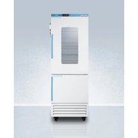
ARFG15PVLHD - Fridge Accucold - Free user manual and instructions
Find the device manual for free ARFG15PVLHD Accucold in PDF.


User questions about ARFG15PVLHD Accucold
0 question about this device. Answer the ones you know or ask your own.
Ask a new question about this device
Download the instructions for your Fridge in PDF format for free! Find your manual ARFG15PVLHD - Accucold and take your electronic device back in hand. On this page are published all the documents necessary for the use of your device. ARFG15PVLHD by Accucold.
USER MANUAL ARFG15PVLHD Accucold
Combined Refrigerator & Freezer
User Manual
Models
ARFS18PV ARFS18PVMC MLRFS18 HCRFS181
ARFG18PV ARFG18PVMC MLRFG18 HCRFG182
ARFS15PV ARFS15PVMC MLRFS15 HCRFS151
ARFG15PV ARFG15PVMC MLRFG15 HCRFG152
BEFORE USE, PLEASE READ AND FOLLOW ALL SAFETY RULES AND OPERATING INSTRUCTIONS
Write Model and Serial Numbers here:
Model:
Serial No:
Accucold Division of Felix Storch, Inc.
An ISO 9001:2015 registered company
770 Garrison Avenue
Bronx, NY 10474
www.accucold.com
TABLE OF CONTENT
EQUIPMENT SAFETY 2
INSTALLATION INSTRUCTIONS 5
LOCATION OF PARTS 8
SPECIFICATION 9
OPERATION-QUICKSETUPGUIDE 10
DETAILED TEMPERATURE CONTROLLER GUIDE 13
CIRCUIT DIAGRAM 20
DEFROSTING 21
CLEANING AND MAINTENANCE 21
TROUBLESHOOTING 22
LIMITED WARRANTY 23
EQUIPMENT SAFETY
Your safety and the safety of others are very important.
This manual and your appliance include important safety instructions. Always read and follow all safety warnings and instructions carefully.

This is the Safety Alert Symbol. The symbol alerts you to potential hazards that can injure you and others. All safety messages will follow Safety Alert Symbol and either the words "DANGER" or "WARNING".

DANGER

DANGER means that failure to heed this safety statement may result in severe personal injury or death.

WARNING

WARNING means that failure to heed this safety statement may result in extensive product damage, serious personal injury, or death.

WARNING: Low temperature/freezing conditions, frostbite hazard.

WARNING: Flammable Material
All safety messages are designed to alert you to potential hazards, explain how to reduce the risk of injury, and describe the possible consequences of not following the instructions.

Before the equipment is used, it must be properly positioned and installed as described in this manual, so read the manual carefully. To reduce the risk of fire, electrical shock or injury when using this equipment, follow basic precautions, including the following:

DANGER

- Plug into a grounded 3-prong outlet, do not remove grounding prong, do not use an adapter, and donot use an extension cord.
- Replace all panels before operating.
It is recommended that a separate circuit serving only your unit be provided. Use receptacles that cannot be turned off by a switch or pull chain. - Never clean the equipment parts with flammable fluids. These fumes can create a fire hazard or
explosion. And do not store or use gasoline or other flammable vapors and liquids in the vicinity of this or any other pieces of equipment. The fumes can create a fire hazard or explosion.
- Before proceeding with cleaning and maintenance operations, make sure the power line of the unit is disconnected.
- Do not connect or disconnect the electric plug when your hands are wet.
- Unplug the unit or disconnect power before cleaning or servicing. Failure to do so can result in electrical shock or death.
- Do not attempt to repair or replace any part of the appliance unless specifically instructed to do so in this manual. All other services should be performed by a qualified technician.
-
These units are CFC- and HFC-free and contain a small quantity of propane (R290) and isobutane (R600a). They are environmentally friendly, but flammable. They do not damage the ozone layer, nor do they increase the greenhouse effect. Care must be taken during transportation and setting up of a unit so that no parts of the cooling system are damaged. Leaking coolant can ignite and may damage the eyes.
In the event of any damage: -
Avoid open flames and anything that creates a spark
- Disconnect from the electrical power line
Air the room in which the unit isolated for several minutes -
Contact our Technical Service Department for assistance
-
The more coolant there is in a unit, the larger the room it should be installed in. In the event of a leakage, if the unit is in a small room, there is the danger of combustible gases building up. For every ounce of coolant, at least 325 cubic feet of room space is required. The amount of coolant in the unit is stated on the data plate inside the unit. It is hazardous for anyone other than an Authorized Service Technician to carry out servicing or repairs to this piece of equipment.
Take serious care when handling, moving, and using the unit to avoid either damaging the refrigerant tubing or increasing the risk of a leak. - Replacing component parts and servicing must be done by factory authorized service technician to minimize the risk of possible ignition due to incorrect parts or improper service.

WARNING

FOLLOW WARNING CALLOUTS BELOW ONLY WHEN APPLICABLE TO YOUR MODEL
Use two or more people to move and install unit. Failure to do so can result in back or other injury.
To ensure proper ventilation for your unit, the front of the must be completely unobstructed. Choose a well-ventilated area with temperatures above 60^ (16°C) and below 90^ (32°C). [For optimal performance, install the unit where the ambient temperature is between 72° and 78°F (23°-26°C).] This unit must be installed in an area protected from the elements, such as wind, rain, waterspray or drips.
The unit should not be located next to ovens, grills or other sources of high heat.
- The unit must be installed with all electrical, water and drain connections in accordance with state and local codes. A standard electrical supply (110 V AC only, 60 Hz), properly grounded in accordance with the National Electrical Code and local codes and ordinances, is required.
- Do not kink or pinch the power supply cord of the unit.
The size of the fuse (or circuit breaker) should be 15 amperes.
It is important that the equipment be leveled to work properly. You may need to make several adjustments to level it.
- All installations must be in accordance with local plumbing code requirements.
- Make certain that the pipes are not pinched, kinked or damaged during installation.
- Check for leaks after connection.
- Never allow children to operate, play with, or crawl inside the unit. This is a medical device and should only be handled by trained professionals.
- Do not use solvent-based cleaning agents or abrasives on the interior. These cleaners may damage or discolor the interior.
- Use this equipment only for its intended purpose as described in this Instruction Manual.
- Keep fingers out of the "pinch point" areas. Clearances between the door and cabinet are necessarily small. Be careful closing the door when children are in the area.
- Ensure all ventilation openings are not obstructed.
- Do not use mechanical devices or other to accelerate the defrosting process, other than those recommended by the manufacturer.
- Do not damage the refrigerant circuit.

DANGER
Risk of child entrapment!
- Child entrapment and suffocation are not problems of the past. Junked or abandoned appliances are still dangerous, even if they will "just sit in the garage a few days".
Before discarding your old unit:
Take off the doors
- Leave the shelves in place so that children may not easily climb inside.
-SAVE THESE INSTRUCTIONS-
CALIFORNIA CARB/SNAP DISCLOSURE
This product uses eco-friendly hydrocarbon refrigerant and fully complies with California CARB regulations.
However, we are required by California Law to provide the following disclosure statement in every product sold in California.in C
"This equipment is prohibited from use in California with any refrigerants on the 'List of Prohibited Substances' for that specific end-use, in accordance with California Code of Regulations, title 17, section 95374. This disclosure statement has been reviewed and approved by Felix Storch, Inc. and Felix Storch, Inc. attests, under penalty of perjury, that these statements are true and accurate."
This product does not use any refrigerants on the "List of Prohibited Substances"
INSTALLATION INSTRUCTIONS
Before Using your Equipment
- Remove the exterior and interior packing.
CAUTION: After unpacking you MUST allow this unit to stand upright for at least 2 hours to allow the lubricant and refrigerant to drain back into the compressor and stabilize. Failure to do so may adversely affect the performance and the lifetime of this unit.
Clean the interior surface with lukewarm water using a soft cloth.
Installation of your Equipment
Note: All models are designed for freestanding and indoor use only.
CAUTION: This equipment is designed for the storage of medicine or other medical products. Do not store beverages or perishable food in this unit.
- Place the unit on a floor that is strong enough to support it when it is fully loaded. To level the unit, adjust the front leveling legs.
- For free-standing installation, allow at least 5 inches (127 mm) of clearance at the back, top, and sides to ensure proper air circulation for cooling the compressor and condenser, which helps save energy.
NOTE: It is recommended that you do not install the unit near an oven, radiator or other heating source. Direct sunlight may affect the acrylic coating and heat sources may increase electrical consumption. Don't install in a location where the temperature will fall below 60^ ( 16^ ). For best performance, do not install the unit behind a cabinet door or block the base grille.
- Avoid locating the unit in moist areas.
- Plug the unit into an exclusive, properly grounded wall outlet. Do not under any circumstances cut or remove the third (ground) prong from the power cord. Any questions concerning power and/or grounding should be directed toward a certified electrician or an authorized service center.
Electrical Connection
WARNING
Improper use of the grounded plug can result in the risk of electrical shock. If the power cord is damaged, have it replaced by a qualified electrician or an authorized service center.
This unit should be properly grounded for your safety. The power cord of this unit is equipped with a three-prong plug which matches the standard three-prong wall outlets to minimize the possibility of electrical shock.
Do not under any circumstances cut or remove the third (ground) prong from the power cord supplied. For personal safety, this equipment must be properly grounded.
This unit requires a standard 110 Volt AC ~ 60Hz three-prong grounded electrical outlet. Have the wall outlet and circuit checked by a qualified electrician to make sure the outlet is properly grounded. When a standard 2-prong wall outlet is encountered, it is your responsibility and obligation to have it replaced with a properly grounded 3-prong wall outlet.
To prevent accidental injury, the cord should be secured behind the unit and not left exposed or dangling.
The unit should always be plugged into its own individual electrical outlet which has a voltage rating that matches the rating label on the unit. This provides the best performance and prevents overloading house wiring circuits that could cause a fire hazard from overheating. Never unplug the unit by pulling on the power cord. Always grip the plug firmly and pull straight out from the receptacle. Repair or replace immediately all power cords that have become frayed or otherwise damaged. Do not use a cord that shows cracks or abrasion damage along its length or at either end. When moving the equipment, be careful not to damage the power cord.
Because of potential safety hazards under certain conditions, it is strongly recommended that you do not use an extension cord with this equipment. However, if you must use an extension cord it is absolutely necessary that it be a UL/CUL-Listed, 3-wire grounding type equipment extension cord having a grounding type plug and outlet and that the electrical rating of the cord be 115 volts and at least 10 amperes.
Reversing the Door
Unless the unit was ordered with the 'LHD' (left-hand door) option, it has been shipped with a right-hand, self-closing door swing. If you wish to reverse the door to open from the opposite direction, please follow the steps outlined below.
Note: The door reversal option is not available on all models.
NOTE: Doors on units with 'DL2B' data logger suffix are not reversible.
- Carefully lay the unit on its back and remove the two front leveling legs
- Remove the two hex head screws that connect the door hinges to the body on the bottom of the unit
- Remove the two flathead screws that connect the hinge assembly to the bottom of the door
- Remove the white hinge from the square rod
- Unscrew the top hinge pin from the unit and reinstall on the left side
- Flip the door so the handle is now on the right side
- Push the door onto the top hinge piece.
- Reinstall the hinge assembly on the left side bottom of the door using the flathead screws
- Push the white hinge onto the square rod at a position of 9 o'clock
- Turn the white hinge clockwise until the holes line up with screws located on the bottom of the unit
- Replace the hex head screws and front leveling legs
NOTE: Once the door has been reversed, the Pharma-Vac sticker will be upside down.
You can remove and reapply to the preferred position. If you would like a replacement sticker, contact our parts department at parts@summitappliance.com.
CAUTION: After setting the unit upright you MUST allow this unit to stand upright for at least 2 hours to allow the lubricant and refrigerant to drain back into the compressor and stabilize.
Failure to do so may adversely affect the performance and the lifetime of this unit.
LOCATION OF PARTS
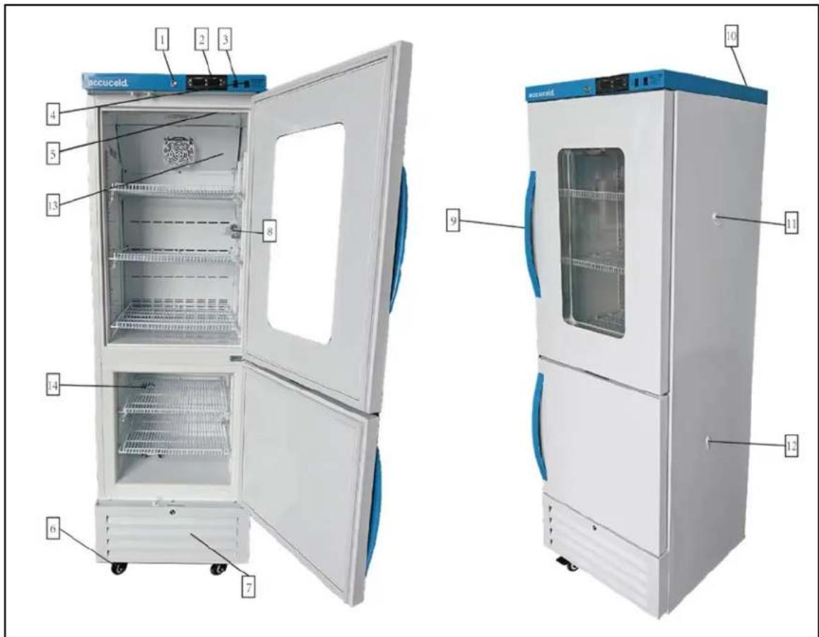
- Keyed Lock
- Microprocessor Control Panel
- Reset Switch
- Light Switch
- Internal Light
- Leveling Legs/Castors
-
Kickplate
-
Temperature Sensor (in glycol bottle)
- Handle
- Dry Contacts (located in rear)
11 & 12. Access Port (for added monitoring devices of the useable area inside the unit) - Refrigerator
- Freezer
Common Places of Use:
Medical laboratories, pharmacies, pharmaceutical factories, and hospitals.
Typical Applications:
Designed for use in medical institutions to store human test samples, vaccines, biological products, reagents, and medications.
SPECIFICATION
| Model | ARFG6PV | ARFS6PV | ARFG15PV | ARFS15PV | ARFG18PV | ARFS18PV |
| Operating Temperature | 0°C-32°C/ 32°F-90°F / 0-85%RH | |||||
| Altitude Up to 2000M | ||||||
| Transport temperature | 0°C to 50°C / 0-85%RH | |||||
| Storage Temperature | -25°C to -10°C/ -13°F to 14°F2°C~8°C/35.6°F~46.4°F | |||||
| Capacity 70L/2.47ft | 3 70L/2.47ft | 3 304L/10.74ft | 3 304L/10.74ft | 3 440L/15.54ft | 3 440L/15.54ft | 3 440L/15.54ft |
| Rated Voltage 110Vac/60Hz | ||||||
| Mains fluctuations | ±10% | |||||
| Frequency 60Hz | ||||||
| Power | 180W | 180W | 210W | 210W | 275W | 275W |
| Shelf load | 20kg each | |||||
| Pollution degree | 2 | |||||
| Refrigerant | R600a/0.92 ozR290/0.84oz | R600a/0.92 ozR290/0.84oz | R600a/1.30 ozR290/1.20 oz | R600a/1.30 ozR290/1.20 oz | R600a/1.44 ozR290/1.27oz | R600a/1.44 ozR290/1.27oz |
| Product dimensionsmm (W*D*H) | 595*649*910 | 595*649*910 | 595*649*1890 | 595*649*1890 | 700*654*2028 | 700*654*2028 |
| Net Weight | 110.2 LBS | 110.2 LBS | 221.12LBS | 221.12LBS | 264.5 LBS | 264.5LBS |
| Foaming material | Cyclopentane | |||||
This section explains how to operate your unit. For more detailed instructions on changing the parameters of the control panel, see page 13.
Once plugged in, the display will show the product temperature inside the freezer and the compressor will start to run (an indicator light on the control panel will turn on at the same time).
NOTE: This unit includes four sensors:
| Compartment | Display Sensor | Control Sensor |
| Refrigerator | Product Sensor | Air Sensor |
| Freezer | Product Sensor | Air Sensor |
For maximum performance, the refrigerator and freezer controls use a separate air sensor to control cooling. This sensor allows it to respond quickly to product loading and door opening. You may need to set the controller to a lower temperature, as the air temperature must be colder than the product to effectively bring it down.
The display shows the product temperature, recorded by a sensor in a glycol-filled vial inside the refrigerator and freezer compartments. As the refrigerator and freezer cool to their set point, the temperature on the display will decrease slowly, since the vial cools more slowly than the air.
IMPORTANT: If power is lost, wait for at least 5 minutes before plugging the unit back in to avoid damaging the compressor.
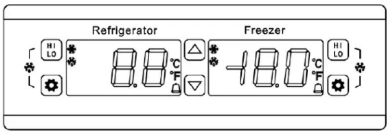
Adjusting the Operating Temperature
To change the set point:
- Press the SET button. The current set point temperature will appear on the display.
- Within 10 seconds, press the up or down arrows until the desired temperature is shown.
- Press the SET button again to confirm and save the new set point.
All models are preset to 4^ (39.2^) and -25^ (-13^) . Adjust the temperature up or down to achieve your desired product temperature the displayed temperature.
High/Low Temperature Alarm
Your refrigerator and freezer have built-in alarms for temperature issues:
- LO: If the temperature drops below the low alarm set point, an alarm will sound and the display will flash [LO] with the current temperature.
- HI: If the air temperature goes above the high alarm set point, an alarm will sound and the display will flash [HI].
H2: If the product temperature goes above the high product alarm set point, an alarm will sound and the display will flash [H2].
There could be several reasons for these alarms, which should be investigated immediately.
Continue monitoring the freezer to ensure it returns to the correct temperature. Alarm thresholds can be adjusted in the parameter setup menu to suit your specific requirements.
Power Failure Alarm
After plugging in the unit, move the Reset Switch (located at the front) to the down position. If power is lost, a battery-powered alarm will sound and stop once power is restored.
Note: The alarm will only sound for a limited time, as it runs on battery power.
Min/Max Temperature Recording
- Once connected to the power supply, your unit records the maximum high and minimum low temperatures reached inside the cabinet. The display will show the last HI and LO temperatures recorded until it is reset.
- To view the HI temperature, press and release the HI/LO button once.
To view the LO temperature, press and release the HI/LO button again.
Resetting the Min/Max Temperature Recording
- Press and hold the HI/LO button for 6 seconds.
- The display will blink, and the buzzer will sound to confirm the reset.
After 5 seconds, the display will return to normal.
Changing the Temperature Display
This unit displays temperature in Celsius by default. To switch to Fahrenheit:
- Press and hold the SET button until [PAS] appears.
- Use the up/down arrows to enter the password (default is 15).
- Press SET repeatedly (about 25 times) until you see [CF] on the screen.
- Press the down arrow to switch to ^
- Press SET once to confirm.
- Wait 6 seconds, the setting will save automatically, and the unit will return to normal operation.
Interior Light
Your unit includes an LED light that automatically turns on when the door is opened.
To keep the light on even when the door is closed, move the switch to the "On" position.
Door Alarm
If the refrigerator or freezer door remains open for more than 3 minutes, an audible alarm will sound. The alarm will stop automatically once the door is closed
Remote Alarm
The electronic controller is equipped with dry contacts for alarm forwarding to an external remote alarm system (terminal block on the back of the unit).
NOTE: The remote contacts are normally "closed" and "open" upon alarm. To change the output to normally "open" and "closed" on alarm see item C12 of the Table of Parameters and Factory Settings. Change the C12 setting to 00 in lieu of 01.
Summary of Alarm Types
| ALARM TYPE | DISPLAY FLASH |
| Air temperature high alarm | HI delay alarm |
| Air temperature low alarm | LO delay alarm |
| Air temperature sensor short circuited | 1H in time alarm |
| Air temperature sensor open circuited | 1L in time alarm |
| Product temperature sensor short circuited | 2H in time alarm |
| Air temperature sensor open circuited | 2L in time alarm |
| Product temperature high temp alarm | H2 delay alarm |
| Product temperature low temp alarm | L2 delay alarm |
| Electric supply off alarm | No display – alarm in time |
| Door open delay alarm | Dr flash and delay alarm |
Storage of Articles
- At maximum loading level, the content should not touch the inner wall of unit.
- Leave space around the contents to prevent freezing, be sure the articles do not touch the back of the interior cabinet.
- Store articles away from the wall.
Shelves can be adjusted to allow proper airflow around the products being stored.
DETAILED TEMPERATURE CONTROLLER GUIDE
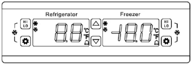
Front Panel Operation
Set Temperature Adjustment (compressor's top temperature):
- Press the SET button, the set temperature is displayed
- Press the UP or DOWN arrow to store and memorize.
- Press the SET button to exit the adjustment status and display the product temperature.
If no more buttons are pressed within 6 seconds, the temperature of the products stored in the unit will display. (Set temperature adjustment range: Parameter E1~E2)
Defrost Indicator LED:
During the active defrosting, the defrost LED will be on. The LED flashes after defrost during the delay period.
Refrigeration LED:
During active cooling, the snowflake LED will be on.
When the set temperature is reached and cooling stops, the LED will turn off.
Display the Sensor Temperature (C13):
Press the DOWN arrow, the product temperature (or cabinet temperature) will flash display for 6 seconds then return to the regular display.
Parameter Set-Up and Settings (for all settings other than temperature setpoint):
- Press and hold the SET button for 6 seconds to enter the parameter setting (flash and display PAS).
- Enter the password (factory default is 15)
- Press SET and the display will show E1, E2, ...do3 PAS in sequence.
- Press the UP or DOWN arrow and the value of the parameter will be displayed and can be modified and stored.
If no buttons are pressed for 6 seconds, the system will automatically exit and save the new value.
NOTE: Only when in the inner parameter menu (display PAS) and the correct password is entered can the parameter value be adjusted. If the wrong password is entered, the parameter modification will be exited, although the set temperature adjustment is still active. If you forget the password, you will need to resume the factory default settings.
The following are examples of how to change common settings:
A. Enter Password
- Press and hold SET for 6 seconds until [PAS] appears.
- Use the UP/DOWN arrows to enter the password (default password 15).
- Press SET to enter the parameter settings.
B. Change ^ C to ^ F
- Enter the password and press SET about 25 times until [CF] appears.
Use the UP/DOWN arrows to select ^ - Press SET and wait 6 seconds for the settings to apply.
C. Set High Air Alarm
- Enter the password and press SET until [C1] appears.
Use the UP/DOWN arrows to choose your desired setting. - Press SET and wait 6 seconds for the settings to apply.
D. Set Low Air Alarm
- E nter the password and press SET until [C2] appears.
Use the UP/DOWN arrows to choose your desired setting. - Press SET and wait 6 seconds for the settings to apply.
E. Set High Product Alarm
- Enter the password and press SET until [C3H] appears.
Use the UP/DOWN arrows to choose your desired setting. - Press SET and wait 6 seconds for the settings to apply.
F. Set Low Pr oduct Alarm
- Enter the password and press SET until [C3L] appears.
Use the UP/DOWN arrows to choose your desired setting. - Press SET and wait 6 seconds for the settings to apply.
G. Adjust Other Parameters
- Enter the password and press SET until the desired parameter code appears.
Use the UP/DOWN arrow to adjust the settings. - Press SET and wait 6 seconds for the settings to apply.
Recording the Highest and Lowest Temperature
Once the unit is turned on and the C5 delay ends, it will automatically begin recording the highest and lowest temperatures. These records are continuously updated and saved, even if the power is turned off.
- Press HI/LO once to see the highest recorded temperature.
- Press it again to see the lowest recorded temperature.
- To clear the temperature readings, press and hold HI/LO for 6 seconds. The display to flash and the unit will sound. A new record will start.
Temperature Recording Conditions
- When F4 = 0 , the temperatures are recorded at all times.
- When F4 = 1,2, or 3, temperatures are not recorded during defrost and the 20-minute delay afterward.
- Temperatures are not recorded during an air sensor failure.
- When C13 = 00, the unit records the product temperature (from the liquid-filled bottle sensor).
- When C13 = 01, the air temperature of the cabinet is recorded.
Factory Default Resumption
To reset all parameters to factory default settings:
- Press and hold the UP and DOWN arrows simultaneously for 6 seconds.
- The display will show [888].
- After 6 seconds, the unit will return to normal operation with default settings restored.
Check or Change the Password
- Press and hold SET for 6 seconds until [PAS] appears.
- Enter the password then press SET
- Use the UP/DOWN arrows to display and change the password
- Press HI/LO to confirm and save the new password.
Refrigerator Parameters and Factory Default Settings
| Parameter | Function | Set Range | Default | Parameter | Function | Set Range | Default |
| Set | Setpoint | 4°C | C3H | Product Temp. High Temp. Alarm | 0~20.0°C / -32~68.0°F | 8°C / 46.4°F | |
| PAS | Password | 00~99 | 15 | C3L | Product Temp. Low Temp. Alarm | 0~20.0°C / -32~68.0°F | 2.0°C / 35.6°F |
| E1 | Lowest set point limit | 2.0°C / 35.6°F | 2.0°C / 3.6°F | C4 | Hysteresis Alarm | 0.1~20.0°C / 0.2~36.0°F | 0.1°C / 0.2°F |
| E2 | Higher setpoint limit | 10.0°C / 50.0°F | 10°C / 50°F | C5 | Start-up Temp. Alarm Delay | 00~99 min | 99 min |
| E3 | Temp. Hysteresis | 0.1~20.0°C / 0.2~36.0°F | 2°C / 3.6°F | C6 | Temp. Alarm Delay | 00~99 min | 0 min |
| E40 | Turning on delay time | 00 ~10 min. | 2 min. | C7 | Power Off Relay Alarm | 00=do not alarm / 01=alarm | 01 |
| E41 | Comp. start delay time | 00 ~10 min. | 2 min. | C8 | Alarm Relay Close After, Muffle Alarm Relay Switch | 00=open / 01=close | 00 |
| E5 | Offset on Air Temperature | -10.0~10.0°C / -18.0~18.0°F | ARFG15PV 3.5°C / 6.3°F ARFG18PV 2.5°C / 4.5°F | C9 | Restart Time After Buzzer Mute | 00=do not start / 01~30 min=restart time | 10 min |
| E6 | Offset on Product Temp. | -10.0~10.0°C / -18.0~18.0°F | 0.0°C / 0.0°F | C10 | Comp. Force Stop Time | 01~99 min | 99 min |
| F0 | Defrost Type | 00=defrost by turning off comp. | 00 | C11 | Comp. Force Running Time | 00=comp. Stop / 01-99min=starting time | 0 min |
| F1 | Max defrost duration | 01~60 min. | 20 min. | C12 | Alarm Output Type | 00=contact actuation when alarm / 01=contact disconnect when alarm | 01 |
| F2 | Defrost Interval (XXhr/time) | 00~24 hr. | 00hr | C13 | Normal State temp. display type | 00=liquid bottle temp / 01=cabinet air temp. | 00 |
| F4 | Temp. displaying on screen when defrost | 00=normal Temp 01=latest Temp 02=Fixed Temp 03=showing "dEF" on screen | 00 | CF | Temperature Unit | °C=Celsius / °F=Fahrenheit | °C |
| C1 | High Temp Air Alarm | 0~20.0°C / -32~68.0°F | 9°C / 48.2°F | do1 00=do not alarm / | 01=99 min=delayed alarm | 02 min | |
| C2 | Low Temp Air Alarm | 0~20.0°C / -32~68.0°F | 1.0°C / 33.8°F | do2 | Comp. status when door open | 0=stop / 01=original status | 01 |
| do3 | Light status when door open | 00=start / 01=original status | 01 |
Freezer Parameters and Factory Default Settings
| Parameter | Function | Set Range | Default | Parameter | Function | Set Range | Default |
| Set | Setpoint | -25°C | C3H | Product Temp. High Temp. Alarm | -10~ -30°C / 14°F- -22°F | -15°C / 5°F | |
| PAS | Password | 00~99 | 15 | C3L | Product Temp. Low Temp. Alarm | -10~ -30°C / 14°F- -22°F | -30°C / -22°F |
| E1 | Lowest Set Point Limit | -30°C / -22°F ~ set temp. | -30°C / -22°F | C4 | Hysteresis Alarm | 0.1~20.0°C / 0.2~36.0°F | 0.1°C / 0.2°F |
| E2 | Higher Set Point Limit | Set temp.~ 10.0°C / 14°F | 10.0°C / 50°F | C5 | Start-Up Temp. Alarm Delay | 00~99 min | 99 min |
| E3 | Temp. Hysteresis | 0.1 ~20.0°C / 0.2 ~36.0°F | 2.0°C / 3.6°F | C6 | Temp. Alarm Delay | 00~99 min | 0 min |
| E40 | Turning On Delay Time | 00~10 min. | 3 min. | C7 | Power Off Relay Alarm | 00=do not alarm / 01=alarm | 01 |
| E41 | Comp. Start Delay Time | 00~10 min. | 3 min. | C8 | Alarm Relay Close After, Muffle Alarm Relay Switch | 00=open / 01=close | 00 |
| E5 | Offset On Air Temperature | -10.0~10.0°C / -18.0~18.0°F | ARFG15PV 1.0°C / 1.8°F ARFG18PV 2.5°C / 4.5°F | C9 | Restart Time After Buzzer Mute | 00=do not start / 01~30 min=restart time | 10 min |
| E6 | Offset On Product Temp. | -10.0~10.0°C / -18.0~18.0°F | 0.0°C / 0.0°F | C10 | Comp. Force Stop Time | 01~99 min | 99 min |
| F0 | Defrost Type | 00=defrost by turning off comp. | 00 | C11 | Comp. Force Running Time | 00=comp. Stop / 01~99min=starting time | 0 min |
| F1 Max | Defrost Duration | 01~60 min. | 0 min. | C12 | Alarm Output Type | 00=contact actuation when alarm / 01=contact disconnect when alarm | 01 |
| F2 | Defrost Interval (Xhr/Time) | 00~24 hr. | 00 | C13 | Normal State Temp. Display Type | 00=liquid bottle temp / 01=cabinet air temp. | 00 |
| F4 Temp. Displaying on Screen When Defrost | 00=normal Temp 01=latest Temp. 02=Fixed Temp. 03=showing "dEF" on screen | 00=normal Temp 01=latest Temp. 02=Fixed Temp. 03=showing "dEF" on screen | 00 | CF | Temperature Unit | °C=Celsius °F=Fahrenheit | °C |
| C1 | High Temp Air Alarm | -10°C ~ -30°C / 14°F ~ -22°F | -15°C / -5°F | do1 | 00=do not alarm / 01=99 min=delayed alarm | 2 min | |
| C2 | Low Temp Air Alarm | -10°C ~ -30°C / 14°F ~ -22°F | -35°C / -31°F | do2 | Comp. Status When Door Open | 0=stop / 01=original status | 01 |
| do3 | Light Status When Door Open | 00=start / 01=original status | 01 |
FUNCTION DETAILS
Temperature Control:
After the unit is powered on and the delay time (parameter E40) has passed, the compressor will:
- Turn ON when the cabinet temperature is higher than set temperature + hysteresis.
- Turn OFF when the cabinet temperature is lower than the set point temperature.
To prevent damage, the compressor will not restart until the delay time (Parameter E41) has elapsed after shutting off.
Defrost Control:
The unit automatically enters defrost mode after operating for a set interval (parameter F2), then the compressor will stop. Defrost continues for the duration set by (parameter F1). After a defrost period ends, there will be 2 minutes of dripping time before the unit resumes refrigeration.
F2 = 00: The automatic defrost will be disabled and the compressor will not shut off or defrost.
- F4 = 0: The temperature will display during defrost.
- F4 = 1: The cabinet temperature is locked during defrost and the last value before defrosting will display. When defrost ends, the display returns to normal after 20 minutes (or when the cabinet temperature is lower than the set temperature). The defrost LED flashes during the delay.
- F4 = 2: The set temperature will be displayed during defrost. When the defrost ends, the display will return to normal after the 20 minutes delay (or cabinet temperature lower than the set temperature). The defrost LED flashes during delay.
- F4 = 3: The display shows [dEF] during defrost. When the defrost ends, the display will return to normal after the 20 minutes delay (or cabinet temperature lower than the set temperature). The defrost LED flashes during delay.
Alarm Control:
After powering on the unit for the first time, it must pass the C5 delay time before temperature alarms (C1, C2, C3) become active.
Air Temperature Alarms:
If the cabinet temperature rises above the high alarm (C1) or falls below the low alarm (C2) for longer than the alarm delay (C6), an alarm will activate:
- Hig h Temperature Alarm - Display alternates [H1] and the cabinet air temperature. The compressor turns on.
When cabinet temperature is lower than (high temperature alarm value C1 -alarm hysteresis C4), the high temperature alarm ends.
- Low Temperature Alarm - Display alternates [LO] and the cabinet air temperature. The compressor turns off.
When cabinet temperature is higher than the (low temperature alarm value C2 + alarm hysteresis C4), the low temperature alarm ends.
Product Sensor High Temp Alarm:
When the product sensor temperature is greater than or equal to the product temperature high temperature alarm value C3 and duration more than alarm delay time C6, unit enters alarm status, and starts the alarm, alternate display [H2] and cabinet temperature. When the product sensor temperature is less than or equal to the (high temperature alarm value C3 - alarm hysteresis C4), it will end the high temperature alarm.
Power Failure Alarm:
If power is lost, the display will flash [EEL] and an alarm will sound.
Door Alarm (do1 setting):
- do1 = 00: No alarm when door is open
- do1 = 0: After the set delay, the display shows [dr alarm]; press any button to cancel
Alarm Relay and Buzzer Behavior:
- C7 = 0 , then the units relay does not alarm when power is off.
- C8 = 0 , then after alarm is canceled, the alarm relay does not close.
- C9 = 0 , then after the alarm cancel button is pushed, the buzzer does not restart.
If setting other numbers, then after reaching delay time, buzzer sounds one more time. (Under the condition of alarm not terminating)
Abnormal Work Mode:
Air Sensor Faults
- When the air sensor is short-circuited or high temperature over limit (>66^ / 151^) the display will show [1H]
- When the air sensor is open-circuited or low temperature over limit (< -40^ / ^) the display will show [1L]
- Compressor will enter the force running mode, according to C10/C11 setparameters running in sequence.
Product Sensor Faults
- Short-circuit or temp >66^ (151°F): Display alternates [2H] and air temperature
- Open-circuit or temp < -40^ (-40°F): Display alternates [2L] and air temperature
Instrument Running Alarm Indication List
| Alarm Type | Compressor Running | Display Flash |
| Freezer high temp. alarm | Compressor on | H1 delay alarm |
| Freezer low temp. alarm | Compressor off | L0 delay alarm |
| Air temp. sensor short-circuited | Press C10, C11 to run the comp. | 1H in time alarm |
| Air temp. sensor open-circuited | Press C10, C11 to run the comp. | 1L in time alarm |
| Product temp. sensor short-circuited | 2H in time alarm | |
| Product temp. sensor open-circuited | 2L in time alarm | |
| Product temperature high temp. | Limit alarm | H2 delay alarm |
| Product temperature low temp. | Limit alarm | L2 delay alarm |
| Electric supply off alarm | No display and alarm in time | |
| Door open delay alarm | Dr flash and delay alarm |
When the door is open, the light switch can turn the light on and off.
CIRCUIT DIAGRAM
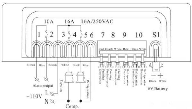
When the door is closed, normal close contact When the door is open, contact is disconnected
Installation Notes:
- Keep sensor leads separate from high-voltage power wires to prevent electrical noise.
- Use a separate power supply for the load and the controller.
- When installing the sensor, position the sensor head upward and the wire downward.
- Do not install the temperature controller in areas exposed to water or dripping moisture.
DEFROSTING
Refrigerator Compartment - Cycle Defrost
The refrigerator compartment features an adjustable cycle defrost operation. The defrost cycle can be initiated automatically via the controller or manually by the user. By default, the compressor shuts off for a maximum of 20 minutes during the defrost mode. However, the default defrost interval is set to zero (0), so the defrost cycle does not run automatically under normal conditions unless it's manually activated.
Manual Refrigerator Defrost
- Press HI/LO button
- Press and hold the SET button for 6 seconds to enter or exit defrost mode.
Freezer Compartment - Manual Defrost
The freezer compartment requires manual defrosting. For optimal performance, defrost the freezer when approximately 14 inch of ice has accumulated inside the cabinet. Before defrosting, remove all contents from the freezer and set the controller to the warmest temperature (10°C). Leave the door open until all ice and frost have fully melted.
To accelerate defrosting, you may place a container of warm water (approximately 125^ ) inside the cabinet. Use clean towels or a sponge to soak up any water, and ensure the interior is completely dry before resetting the thermostat to its normal temperature.
IMPORTANT: It is not advisable to heat the interior of the freezer directly with hot water or a hair dryer while defrosting since this can deform the cabinet interior.
NEVER USE A METAL OBJECT TO REMOVE ICE FROM THE REAR WALL. IF NEEDED, USE A PLASTIC ICE-SCRAPER.
CLEANING AND MAINTENANCE
Before cleaning, it is essential that you unplug the unit from the power line and transfer the contents where they can be stored and monitored at the correct temperatures.
Use warm water and a neutral detergent to clean the interior compartment.
- Do not allow the control panel, power cord, or plug to get wet.
- Never use corrosive cleaners, wire brushes, abrasive pads, or sharp tools to clean the unit.
Thoroughly dry all surfaces before restarting the unit.
- The condenser is located at the back of the cabinet. To ensure trouble-free operation, the condenser should be cleaned every three months where appropriate using a vacuum hose.
- In exceptionally dusty locations, the condenser should be cleaned more often.
When moving the unit, keep it upright. The angle between the unit and the horizontal surface should be at least 50^ . Tilting below this angle may damage the compressor and affect normal operation.
TROUBLESHOOTING
You can solve many common problems easily, saving you the cost of a possible service call. Try the suggestions below to see if you can solve the problem before calling the servicer.
| Problems | Possible causes | Remedy |
| The unit does not operate | Bad connection of plug | Unplug the power cord andre-connect the plug to power supply. |
| Abnormal operation of the compressor or there is a buzzing sound | The power voltage is out of rated range | Disconnect the power supply immediately and reconnect with it after normal voltage. It is necessary to have a voltage stabilizer in case of poor power supply. |
| Compressor operates for a long time and no frost on the surface of the evaporator | Refrigeration system is at fault(leakage or blocked) | Call for service |
| There is frost or ice on the walls of the inner cabinet, and the internal temperature is too low, the compressor never stops running. | Thermostat does not work | Call for service |
| The temperature setting of thethermostat is too low. | Adjust to a higher temperature | |
| The internal temperature is too high, and the compressor never stops operating. | Bad heat dissipation and ventilation ofcondenser | Improve ventilation |
| Too many warm items were put in atone time | Remove some goods so the air can circulate | |
| Door is being opened too frequentlyduring initial cool down | Permit the unit to cool down adequately, preventproduct access during this | |
| Too noisy | The unit is not level | Adjust the adjustable legs |
| The fastener of the unit is loose | Tighten the loose fastener | |
| Pipe near the compressor is touching | Carefully separate the touching pipes | |
| The side of the unit is hot | The condenser in the side wall givesout heat as part of normal operation | Nothing to worry about. |
| Sometimes a light soundof water flowing will be heard | Refrigerant flowing inside the pipe. | Nothing to worry about. |
| There may be condensation on the Solid door | High ambient temperature or humid conditions | Dry with a cloth |
| The display shows "So" and compressor does not run | The temperature sensor is open circuit | Call for service |
| The display shows "SC" and compressor does not run | The temperature sensor is short circuited. | Call for service |
| The display shows "HH" and compressor does not run | The ambient temperature is above 40°C/104°F | Stop using immediately |
| The display shows "LL" and compressor does not run | The ambient temperature is below - 45°C/-49°F. | Stop using immediately |
If you continue to experience issues, contact Accucold's technical support department at 1-888-4-MEDLAB or visit our website https://www.accucold.com/support.
LIMITED WARRANTY
TWO-YEAR LIMITED WARRANTY
Warranty coverage is available within the 48 contiguous United States, along with select areas of Alaska, Hawaii, and Canada. For locations not covered, consumers can either contact a local provider or coordinate with Felix Storch, Inc. to find nearby service options, which may qualify for partial reimbursement.
The warranty for this appliance is valid for two years from the date of purchase, provided the appliance is operated and maintained according to the instructions included with the product. The warrantor will cover the cost of factory-specified parts and repair labor needed to correct defects in materials or workmanship. Service must be performed by a designated service company.
All parts, except the compressor, are warranted for two years against manufacturing defects. Plastic parts, shelves, and cabinets are produced to commercially acceptable standards but are not covered for damages incurred during handling or for breakage.
5-YEAR COMPRESSOR WARRANTY
- The compressor is covered for 5 years.
- Replacement does not include labor.
ITEMS WARRANTYOR WILL NOT PAY FOR:
- Service calls to correct the installation of your appliance, to instruct you how to use your appliance, to replace or repair fuses or to correct wiring or plumbing.
- Service calls to repair or replace appliance light bulbs or broken shelves. Consumable parts (such as filters) are excluded from warranty coverage.
- Damage resulting from accident, alteration, misuse, abuse, fire, flood, acts of God, improper installation, installation not in accordance with electrical or plumbing codes, or use of products not approved by warrantor.
- Replacement parts or repair labor costs for units operated outside the 48 contiguous United States, along with select areas of Alaska, Hawaii, and Canada.
- Repairs to parts or systems resulting from unauthorized modifications made to the appliance.
- Expenses for travel and transportation for product service in remote locations.
- The removal and reinstallation of your appliance if it is installed in an inaccessible location or is not installed in accordance with published installation instructions.
DISCLAIMER OF IMPLIED WARRANTY; LIMITATION OF REMEDIES
CUSTOMER'S SOLE AND EXCLUSIVE REMEDY UNDER THIS LIMITED WARRANTY SHALL BE PRODUCT REPAIR AS PROVIDED HEREIN. IMPLIED WARRANTY, INCLUDING WARRANTY OF MERCHANTABILITY OR FITNESS FOR A PARTICULAR PURPOSE, ARE LIMITED TO TWO YEARS. WARRANTYOR SHALL NOT BE LIABLE FOR INCIDENTAL OR CONSEQUENTIAL DAMAGES. SOME STATES DO NOT ALLOW THE EXCLUSION OR LIMITATION OF INCIDENTAL OR CONSEQUENTIAL DAMAGES, OR LIMITATIONS ON THE DURATION OF IMPLIED WARRANTY OF MERCHANTABILITY OR FITNESS, SO THESE EXCLUSIONS OR LIMITATIONS MAY NOT APPLY TO YOU. THIS WARRANTY GIVES YOU SPECIFIC LEGAL RIGHTS AND YOU MAY ALSO HAVE OTHER RIGHTS, WHICH VARY FROM STATE TO STATE.

WARNING: This product can expose you to chemicals including Nickel (Metallic) which is known to the State of California to cause cancer.
For more information go to www.P65Warnings.ca.gov
Note: Nickel is a component in all stainless steel and some other metallic compositions.
Accucold Division of Felix Storch, Inc.
An ISO 9001:2015 registered company
770 Garrison Avenue
Bronx, NY 10474
accucold.
For parts and accessory ordering,
troubleshooting and helpful hints, visit:
www.accucold.com/support
Revised: 2025-08-26
Division Accucold de Felix Storch, Inc.
Accucold Division of Felix Storch, Inc.
An ISO 9001:2015 registered company
770 Garrison Avenue
Bronx, NY 10474
accucold.
For parts and accessory ordering, troubleshooting and helpful hints, visit: www.accucold.com/support