
MADA50R5AWT - Dehumidifier MIDEA - Free user manual and instructions
Find the device manual for free MADA50R5AWT MIDEA in PDF.

User questions about MADA50R5AWT MIDEA
0 question about this device. Answer the ones you know or ask your own.
Ask a new question about this device
Download the instructions for your Dehumidifier in PDF format for free! Find your manual MADA50R5AWT - MIDEA and take your electronic device back in hand. On this page are published all the documents necessary for the use of your device. MADA50R5AWT by MIDEA.
USER MANUAL MADA50R5AWT MIDEA
natural_image
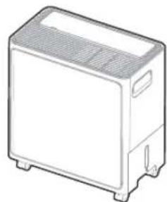
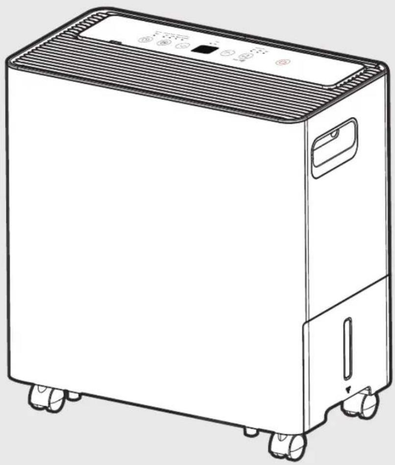
Line drawing of a portable air purifier with control panel and wheels (no text or symbols)Dehumidifier
MAD
USER MANUAL
MDA22C4WWCM
MADA35R5AWT
MADA50R5AWT

Warning notices: Before using this product, please read this manual carefully and keep it for future reference.
The design and specifications are subject to change without prior notice for product improvement.
Consult with your dealer or manufacturer for details.
The diagram above is just for reference. Please take the appearance of the actual product as the standard.
THANK YOU LETTER
Thank you for choosing Midea! Before using your new Midea product, please read this manual thoroughly to ensure that you know how to operate the features and functions that your new dehumidifier offers in a safe way.
CONTENTS
THANK YOU LETTER 2
SAFETY INSTRUCTIONS ....3
GET TO KNOW YOUR PRODUCT....13
PRODUCT INSTALLATION ....14
GET TO KNOW YOUR FEATURES ....17
REMOVING COLLECTED WATER 21
CLEANING AND MAINTENANCE....24
TROUBLESHOOTING TIPS 26
WARRANTY 27
Read This Manual
Inside you'll find many helpful hints on how to use and maintain your dehumidifier properly. Just a little preventive care on your part can save you a great deal of time and money over the life of your appliance. You'll find many answers to common problems in the troubleshooting tips - you should be able to fix most of them quickly before calling service. These instructions may not cover every possible condition of use, so common sense and attention to safety is required when installing, operating and maintaining this product.

CAUTION
- For support, please call the Service Center at 1-888-365-2230.
- This appliance is not intended for use by people (including children) with reduced physical, sensory, or mental capabilities or lack of experience and knowledge, unless they have been given supervision or instruction concerning use of the appliance by a person responsible for their safety.
• Children should be supervised to ensure that they do not play with the appliance. - The appliance shall be installed in accordance with national wiring regulations.
SAFETY PRECAUTIONS
Read Safety Precautions Before Operation and Installation To prevent death or injury to the user or other people and property damage, the following instructions must be followed. Incorrect operation due to ignoring of instructions may cause death, harm or damage.
Explanation of Symbols

WARNING
The signal word indicates a hazard with a medium level of risk which, if not avoided, may result in death or serious injury.

CAUTION
The signal word indicates a hazard with a low degree of risk which, if not avoided, may result in minor or moderate injury.

WARNING
- Do not exceed the rating of the power outlet or connection device.
- Do not operate or stop the unit by switching on or off the power.
- Do not damage or use an unspecified power cord.
- Do not modify power cord length or share the outlet with other appliances.
- Do not insert or pull out plug with wet hands.
- Do not insert or pull out plug with wet hands.
- Do not install the appliance in a location that may be exposed to combustible gas.
- Do not place the unit near a heat source.
- Do not place the unit near a heat source.
- Disconnect the power if strange sounds, smell, or smoke comes from it.
- You should never try to take apart or repair the unit by yourself.
- Before cleaning, turn off the power and unplug the unit.
- Do not use the machine near flammable gas or combustibles, such as gasoline, benzene, thinner, etc.
- Do not drink or use the water drained from the unit.
- Do not take the water bucket out during operation.
- Do not use the unit in small spaces.
- Do not put in places where water may splash onto the unit.
- Place the unit on a level, sturdy section of the floor.
- Do not cover the intake or exhaust openings with cloths or towels.
- Care should be taken when using the unit in a room with the following persons: infants, children, elderly people, and people not sensitive to humidity.
- Do not use in areas where chemicals are handled.
- Never insert your finger or other foreign objects into grills or openings. Take special care to warn children of these dangers.
- Do not place heavy object on the power cord and take care so that the cord is not compressed.
- Do not climb up on or sit on the unit.
• Always insert the filters securely. Clean filter once every two weeks. - If water enters the unit, turn the unit o and disconnect the power, contact a qualified service technician.
- Do not place flower vases or other water container on top of the unit.
- Do not use extension cords.

CAUTION
- This appliance is not intended for use by persons (including childern) with reduced physical, sensory or mental capabilities or lack of experience and knowledge, unless they have been given supervision or instruction concerning use of the appliance by a person responsible for their safety.
- Children should be supervised to ensure that they do not play with the appliance.
- If the supply cord is damaged, it must be replaced by the manufacturer, its service agent or similarly qualified persons in order to avoid a hazard.
- Prior to cleaning or other maintenance, the appliance must be disconnected from the supply mains.
- Do not install the appliance in a location that may be exposed to combustible gas. If combustible gas accumulates around the unit, it may cause fire.
- If the appliance is knocked over during use, turn off the unit and unplug it from the main power supply immediately. Visually inspect the unit to ensure there is no damage. If you suspect the unit has been damaged, contact a technician or customer service for assistance.
- Our product will not be used in a water damage environment.
- In a thunderstorm, the power must be cut to avoid damage to the machine due to lightning.
- Do not run cord under carpeting. Do not cover cord with throw rugs, runners, or similar coverings. Do not route cord under furniture or appliances. Arrange cord away from trac area and where it will not be tripped over.
- Do not operate unit with a damaged cord or plug. Discard unit or return to an authorized service facility for examination and/or repair.
- To reduce the risk of fire or electric shock, do not use this fan with any solid-state speed control device.
- The appliance shall be installed in accordance with national wiring regulations.
- Contact the authorised service technician for repair or maintenance of this unit.
- Turn off the product when not in use.
- The manufactures nameplate is located on the panel of the unit and contains electrical and other technical data specific to this unit.
- Be sure the unit is properly grounded. To minimize shock and fire hazards, proper grounding is important.
- The power cord is equipped with a three-prong grounding plug for protection against shock hazards.
- Your unit must be used in a properly grounded wall receptacle. If the wall receptacle you intend to use is not adequately grounded or protected by a time delay fuse or circuit breaker(please refer to the nameplate for the electrical data), have a qualified electrician install the proper receptacle.
- Do not operate your appliance in a wet room such as a bathroom or laundry room.
- The unit s circuit board(PCB) is designed with a fuse to provide overcurrent protection. specifications of the fuse are printed on the circuit board, such as: T 3.15A/250V (or 350V), etc.

WARNING:
BEFORE PERFORMING ANY ELECTRICAL OR WIRING WORK, TURN OFF THE MAIN POWER TO THE SYSTEM.

flowchart
graph TD
    A["Power Supply"] --> B["L/AC L/L1/L-IN"]
    A --> C["N/AC N/L2/N-IN"]
    B --> D["Main Control"]
    C --> D
    E["Display"] --> D
    F["Compressor"] --> D
    G["Fan Motor"] --> D
    H["Other"] --> D
NOTE: Please strictly follow the wiring label attached to the machine for all wiring connections. The wiring diagram may vary for different unit. Please refer to the wiring diagram on the machine you have purchased. The above wiring diagram is a simplified version for preliminary illustration purposes only.
SAFETY MANUAL
FOR R32 REFRIGERANT MODEL
CAUTION:
Risk of fire
flammable materials
IMPORTANT NOTE: Read this manual carefully before installing or operating your new appliance unit. Make sure to save this manual for future reference.
Explanation of symbols displayed on the unit
 | CAUTION | This symbol shows that the operation manual should be read carefully. |
 | CAUTION | This symbol shows that a service personnel should be handling this equipment with reference to the installation manual. |
 | CAUTION | This symbol shows that information is available such as the operating manual or installation manual. |
WARNING:
-Servicing shall only be performed as recommended by the equipment manufacturer. Maintenance and repair requiring the assistance of other skilled personnel shall be carried out under the supervision of the person competent in the use of flammable refrigerants.
- DO NOT modify the length of the power cord or use an extension cord to power the unit.
- DO NOT share a single outlet with other electrical appliances. Improper power supply can cause fire or electrical shock.
- Please follow the instruction carefully to handle, install, clear, service the appliance to avoid any damage or hazard.
Flammable
Refrigerant R32 is used within appliance.
-When maintaining or disposing the appliance, the refrigerant (R32) shall be recovered properly, shall not discharge to air directly.
- Compliance with national gas regulations shall be observed.
- Keep ventilation openings clear of obstruction.
- The appliance shall be stored so as to prevent mechanical damage from occurring.
- The appliance shall be stored in a well-ventilated area where the room size corresponds to the room area as specified for operation.
- Any person who is involved with working on or breaking into a refrigerant circuit should hold a current valid certificate from an industry-accredited assessment authority, which authorises their competence to handle refrigerants safely in accordance with an industry recognised assessment specification. All training shall follow the ANNEX HH requirements of UL 60335-2-40 4th Edition.
Examples for such working procedures are:
- breaking into the refrigerating circuit;
- opening of sealed components;
- opening of ventilated enclosures.
-No open fire or device like switch which may generate spark/arcing shall be around appliance to avoid causing ignition of the flammable refrigerant used. Please follow the instructions carefully when storing or maintaining the appliance to prevent mechanical damage from occurring.
- Do not use means to accelerate the defrosting process or to clean, other than those recommended by the manufacturer.
- The appliance shall be stored in a room without continuously operating ignition sources (for example: open flames, an operating gas appliance) and ignition sourcesor (for example: an operating electric heater) close to the appliance.
- Do not pierce or burn.
-
Be aware that the refrigerants may not contain an odour.
-
Transport of equipment containing flammable refrigerants
See transport regulations.
- Marking of equipment using signs
See local regulations.
- Disposal of equipment using flammable refrigerants
See national regulations.
- Storage of equipment/appliances
The storage of the appliance should be in accordance with the applicable regulations or instructions, whichever is more stringent.
- Storage of packed (unsold) equipment
Storage package protection should be constructed such that mechanical damage to the equipment inside the package will not cause a leak of the refrigerant charge. The maximum number of pieces of equipment permitted to be stored together will be determined by local regulations.
- Information on servicing
1) Checks to the area
Prior to beginning work on systems containing flammable refrigerants, safety checks are necessary to ensure that the risk of ignition is minimised. For repair to the refrigerating system, the following precautions shall be complied with prior to conducting work on the system.
2) Work procedure
Work shall be undertaken under a controlled procedure so as to minimise the risk of a flammable gas or vapour being present while the work is being performed.
3) General work area
All maintenance staff and others working in the local area shall be instructed on the nature of work being carried out. Work in confined spaces shall be avoided. The area around the workspace shall be sectioned off. Ensure that the conditions within the area have been made safe by control of flammable material.
4) Checking for presence of refrigerant
The area shall be checked with an appropriate refrigerating detector prior to and during work, to ensure the technician is aware of potentially flammable atmospheres. Ensure that the leak detection equipment being used is suitable for use with flammable refrigerants, i.e. non-sparking, adequately sealed or intrinsically safe.
5) Presence of fire extinguisher
If any hot work is to be conducted on the refrigeration equipment or any associated parts, appropriate fire extinguishing equipment shall be available to hand. Have a dry powder or CO2 fire extinguisher adjacent to the charging area.
6) No ignition sources
No person carrying out work in relation to a refrigerating system which involves exposing any pipe work that contains or has contained flammable refrigerant shall use any sources of ignition in such a manner that it may lead to the risk of fire or explosion. All possible ignition sources, including cigarette smoking, should be kept sufficiently far away from the site of installation, repairing, removing and disposal, during which flammable refrigerant can possibly be released to the surrounding space. Prior to work taking place, the area around the equipment is to be surveyed to make sure that there are no flammable hazards or ignition risks. No Smoking signs shall be displayed.
7) ventilated area
Ensure that the area is in the open or that it is adequately ventilated before breaking into the system or conducting any hot work. A degree of ventilation shall continue during the period that the work is carried out. The ventilation should safely disperse any released refrigerant and preferably expel it externally into the atmosphere.
8) Checks to the refrigerating equipment
Where electrical components are being changed, they shall be fit for the purpose and to the correct specifications. At all times the manufacturer's maintenance and service guidelines shall be followed. If in doubt consult the manufacturer's technical department for assistance. The following checks shall be applied to installations using flammable refrigerants: the actual refrigerant charge is in accordance with the room size within which the refrigerant containing parts are installed; the ventilation machinery and outlets are operating adequately and are not obstructed; if an indirect refrigerating circuit is being used, the secondary circuit shall be checked for the presence of refrigerant; marking to the equipment continues to be visible and legible. markings and signs that are illegible shall be corrected; and refrigerating pipe or components are installed in a position where they are unlikely to be exposed to any substance which may corrode refrigerant containing components, unless the components are constructed of materials which are inherently resistant to being corroded or are suitably protected against being so corroded.
9) Checks to electrical devices
Repair and maintenance to electrical components shall include initial safety checks and component inspection procedures. If a fault exists that could compromise safety, then no electrical supply shall be connected to the circuit until it is satisfactorily dealt with. If the fault cannot be corrected immediately but it is necessary to continue operation, an adequate temporary solution shall be used. This shall be reported to the owner of the equipment so all parties are advised. Initial safety checks shall include:
That capacitors are discharged: this shall be done in a safe manner to avoid possibility of sparking; that there no live electrical components and wiring are exposed while charging, recovering or purging the system; that there is continuity of earth bonding.
-
Sealed electrical components shall be replaced.
-
Intrinsically safe components must be replaced.
9. Cabling
Check that cabling will not be subject to wear, corrosion, excessive pressure, vibration, sharp edges or any other adverse environmental effects. The check shall also take into account the effects of aging or continual vibration from sources such as compressors or fans.
10. Detection of flammable refrigerants
Under no circumstances shall potential sources of ignition be used in the searching for or detection of refrigerant leaks. A halide torch (or any other detector using a naked flame) shall not be used.
The following leak detection methods are deemed acceptable for systems containing flammable refrigerants. Electronic leak detectors shall be used to detect flammable refrigerants, but the sensitivity may not be adequate, or may need re-calibration.
(Detection equipment shall be calibrated in a refrigerant-free area.)
Ensure that the detector is not a potential source of ignition and is suitable for the refrigerant used. Leak detection equipment shall be set at a percentage of the LFL of the refrigerant and shall be calibrated to the refrigerant employed and the appropriate percentage of gas (25% maximum) is confirmed. Leak detection fluids are suitable for use with most refrigerants but the use of detergents containing chlorine shall be avoided as the chlorine may react with the refrigerant and corrode the copper pipe-work.
If a leak is suspected, all naked flames shall be removed/extinguished. If a leakage of refrigerant is found which requires brazing, all of the refrigerant shall be recovered from the system, or isolated (by means of shut off valves) in a part of the system remote from the leak. Removal of refrigerant shall be according to Removal and evacuation.
11. Removal and evacuation
When breaking into the refrigerant circuit to make repairs—or for any other purpose - conventional procedures shall be used. However, for flammable refrigerants it is important that best practice be followed, since flammability is a consideration. The following procedure shall be adhered to:
-Safely remove refrigerant following local and national regulations;
-Evacuate;
-Purge the circuit with inert gas (optional for A2L);
-Evacuate (optional for A2L);
-continuously flush or purge with inert gas when using flame to open circuit; and -open the circuit.
The refrigerant charge shall be recovered into the correct recovery cylinders if venting is not allowed by local and national codes. For appliances containing flammable refrigerants, the system shall be purged with oxygen-free nitrogen to render the appliance safe for flammable refrigerants. This process might need to be repeated several times. Compressed air or oxygen shall not be used for purging refrigerant systems.
For appliances containing flammable refrigerants, refrigerants purging shall be achieved by breaking the vacuum in the system with oxygen-free nitrogen and continuing to fill until the working pressure is achieved, then venting to atmosphere, and finally pulling down to a vacuum (optional for A2L). This process shall be repeated until no refrigerant is within the system (optional for A2L). When the final oxygen-free nitrogen charge is used, the system shall be vented down to atmospheric pressure to enable work to take place.
The outlet for the vacuum pump shall not be close to any potential ignition sources, and ventilation shall be available.
12. Charging procedures
In addition to conventional charging procedures, the following requirements shall be followed. Ensure that contamination of different refrigerants does not occur when using charging equipment. Hoses or lines shall be as short as possible to minimise the amount of refrigerant contained in them. Cylinders shall be kept in an appropriate position according to the instructions. Ensure that the refrigeration system is earthed prior to charging the system with refrigerant. Label the system when charging is complete (if not already). Extreme care shall be taken not to overfill the refrigeration system. Prior to recharging the system it shall be pressure tested with OFN. The system shall be leak tested on completion of charging but prior to commissioning. A follow up leak test shall be carried out prior to leaving the site.
13. Decommissioning
Before carrying out this procedure, it is essential that the technician is completely familiar with the equipment and all its detail. It is recommended good practice that all refrigerants are recovered safely. Prior to the task being carried out, an oil and refrigerant sample shall be taken in case analysis is required prior to re-use of reclaimed refrigerant. It is essential that electrical power is available before the task is commenced.
a) Become familiar with the equipment and its operation.
b) Isolate system electrically.
c) Before attempting the procedure ensure that: mechanical handling equipment is available, if required, for handling refrigerant cylinders; all personal protective equipment is available and being used correctly; the recovery process is supervised at all times by a competent person; recovery equipment and cylinders conform to the appropriate standards.
d) Pump down refrigerant system, if possible.
e) If a vacuum is not possible, make a manifold so that refrigerant can be removed from various parts of the system.
f) Make sure that cylinder is situated on the scales before recovery takes place.
g) Start the recovery machine and operate in accordance with instructions.
h) Do not overfill cylinders. (No more than 80% volume liquid charge.)
i) Do not exceed the maximum working pressure of the cylinder, even temporarily.
j) When the cylinders have been filled correctly and the process completed, make sure that the cylinders and the equipment are removed from site promptly and all isolation valves on the equipment are closed off.
k) Recovered refrigerant shall not be charged into another refrigeration system unless it has been cleaned and checked.
14. Labelling
Equipment shall be labelled stating that it has been de-commissioned and emptied of refrigerant. The label shall be dated and signed.
Ensure that there are labels on the equipment stating the equipment contains flammable refrigerant.
15. Recovery
When removing refrigerant from a system, either for servicing or decommissioning, it is recommended good practice that all refrigerants are removed safely.
When transferring refrigerant into cylinders, ensure that only appropriate refrigerant recovery cylinders are employed. Ensure that the correct number of cylinders for holding the total system charge is available. All cylinders to be used are designated for the recovered refrigerant and labelled for that refrigerant (i.e., special cylinders for the recovery of refrigerant). Cylinders shall be complete with pressure-relief valve and associated shut-off valves in good working order. Empty recovery cylinders are evacuated and, if possible, cooled before recovery occurs.
The recovery equipment shall be in good working order with a set of instructions concerning the equipment that is at hand and shall be suitable for the recovery of the flammable refrigerant. If in doubt, the manufacturer should be consulted. In addition, a set of calibrated weighing scales shall be available and in good working order. Hoses shall be complete with leak-free disconnect couplings and in good condition.
The recovered refrigerant shall be processed according to local legislation in the correct recovery cylinder, and the relevant waste transfer note arranged. Do not mix refrigerants in recovery units and especially not in cylinders.
If compressors or compressor oils are to be removed, ensure that they have been evacuated to an acceptable level to make certain that flammable refrigerant does not remain within the lubricant. The compressor body shall not be heated by an open flame or other ignition sources to accelerate this process. When oil is drained from a system, it shall be carried out safely.
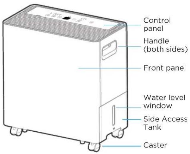
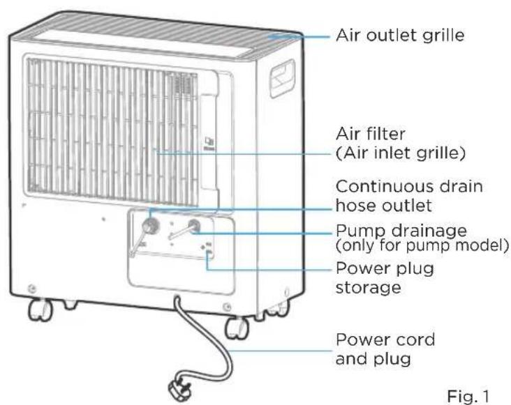
GET TO KNOW YOUR PRODUCT
Identification of Parts
Name of each component of the product

NOTE
All the illustrations in the manual are for explanation purpose only. Your machine may be slightly different. The actual shape shall prevail. The unit can be controlled by the unit control panel.
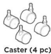
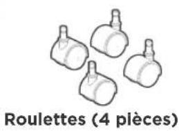
Accessories

NOTE
Items with (*) are on some models. Slight variations in design may occur.
Accessories
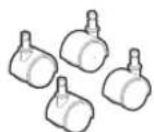
Caster (4 pc)
Optional accessories

pump drain hose(1 pc ^* )
(For the unit with pump feature)

NOTE: Make the drain Hose straight when you use it.
Drain Hose (1 pc ^* )
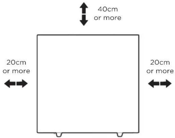
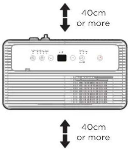
Positioning the Unit
Safe distance requirements
weiv poTwegv2norF

NOTE
Casters (At four points on the bottom of unit)
- Casters can move freely.
- Do not force casters to move over carpet.
- Do not move the unit with water in the bucket. (The unit may tip over and spill water.)
A dehumidifier operating in a basement will have little or no effect in drying an adjacent enclosed storage area, such as a closet, unless there is adequate circulation of air in and out of the area. (See Fig. 2)
- Do not use outdoors.
• This dehumidifer is intended for indoor residential applications only.
• This dehumidifer should not be used for commercial or industrial applications. - Place the dehumidifier on a smooth, level floor strong enough to support the unit with a full bucket of water.
- Allow at least 20cm of air space on all sides of the unit for good air circulation (at least 40cm of air space on air outlet).
- Place the unit in an area where the temperature will not fall below 41°F (5°C). The coils can become covered with frost at temperatures below 41°F (5°C), which may reduce performance.
- Place the unit away from the clothes dryer, heater or radiator.
• Use the unit to prevent moisture damage anywhere books or valuables are stored.
- Use the dehumidifier in a basement to help prevent moisture damage.
• The dehumidifi er must be operated in an enclosed area to be most effective.
- Close all doors, windows and other outside openings to the room.
- Before tilting or moving the unit in any way, take out the bucket, open the continuous drain outlet to empty the water, and disconnect the power cord.
When Using Your Product
Preparations for product use

NOTE
When the water in the bucket reaches to a certain level, please be careful to move the machine to avoid it tipping over.
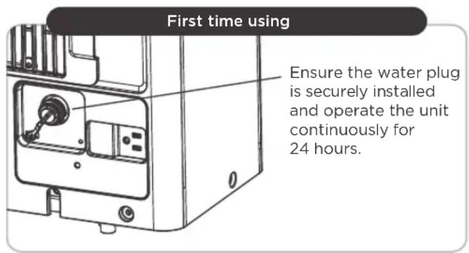
- When first using the dehumidifier, operate the unit continuously for 24 hours. Ensure that the plastic cover is securely installed in continuous dehumidification mode and does not leak.
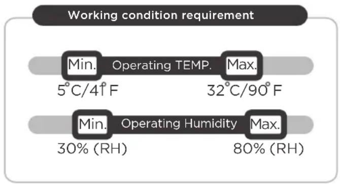
- This unit is designed to operate with a working environment between 5°C/41°F and 32°C/90°F, and between 30% (RH) and 80% (RH).
- When use in open space with open windows, condensation may form on the surface of the product, which is normal.
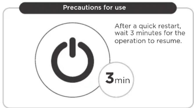
- If the unit has been switched off and needs to be switched on again quickly, allow approximately three minutes for the correct operation to resume.
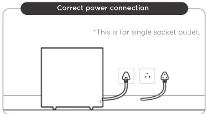
- Do not connect the dehumidifier to a multiple socket outlet, which is also being used for other electrical appliances.
- Select a suitable location, making sure you have easy access to an electrical outlet.
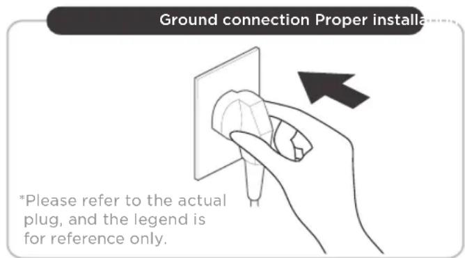
- Plug the unit into an electrical socket-outlet with ground connection.
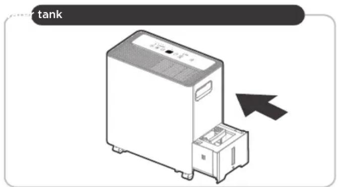
- Make sure the side access tank is correctly fitted otherwise the unit will not operate properly.
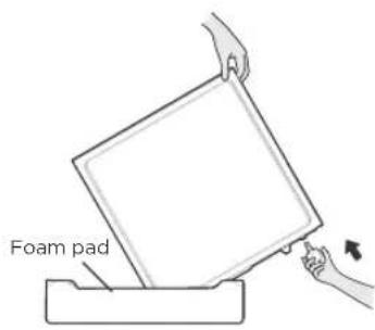
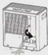
Caster installation
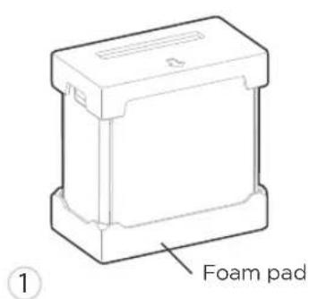
Remove the foam pad for preparation.
natural_image
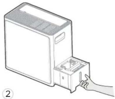
Line drawing of a computer tower with a hand inserting a component into the base (no text or symbols)Pull out the water bucket
natural_image
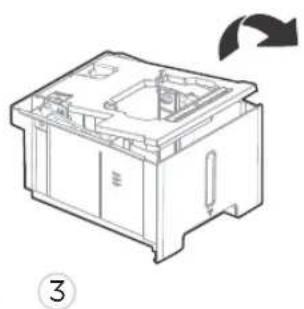
Technical line drawing of a mechanical device casing with internal components and a rotation arrow (no text or symbols)Remove the cover, take out four casters from the bucket, then reinstall the water bucket
Step 1
4
Tilt the unit on the foam pad and hold it with one hand, then insert two casters.
Step 2
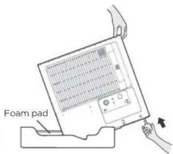
Rotate the unit and hold it with one hand, then insert the other two casters.
natural_image
Line drawing of a rectangular electronic device with ventilation slots and mounting feet (no text or symbols)5
Leave the unit in a vertical position for half an hour before use.
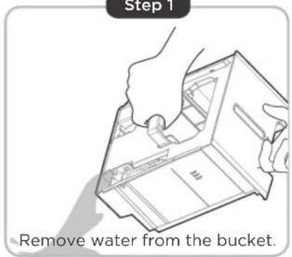
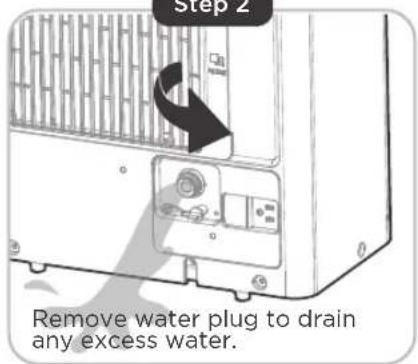
WARNING:
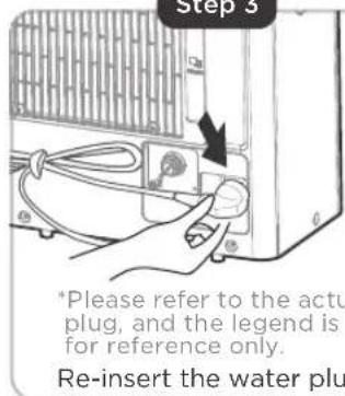
• Take out the bucket and removal water plug, drain the water outlet as shtep 1 and step 2, then reinstall the bucket and water plug before installing casters.
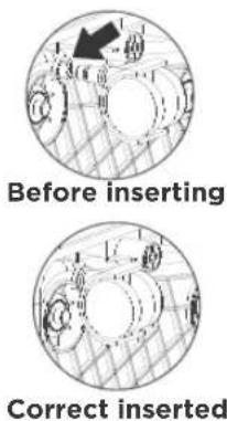
• The tilt Angle DO NOT be greater than 30° when installing casters, and all casters MUST BE installed within 5 minutes.
• After the installation is complete, reset the unit and rest for 30 minutes before starting the unit.
Step 1
natural_image
Illustration of hands using a device to generate a packet (no text or symbols present)Step 2
GET TO KNOW YOUR FEATURES
Control Panel Features
Operation Display

NOTE
The following control panels are for explanation purpose only. The control panel of the unit you purchased may be slightly different according to the models. Your machine may not contain some indicators or buttons. The actual shape will remain the same.

| Description | ||
1 ON / OF  | Press to turn unit on or off. | |
2 TIMER B  | • Press to turn unit Auto Start/Stop. | |
3 Mode B  | • Press to choose operating mode in a sequence:Set → Cont. —Dryer Comfort | |
| 4 |   UP / DOWN Buttons UP / DOWN Buttons | • Press to set humidity and timer. |
5 FAN Bu  reset filter(3s) reset filter(3s) | • Press to select the Fan Speed in two steps: High and Low.• Press to turn off the cleaning filter reminder. | |
| 6 |  LED Display LED Display | • Show the ambient humidity and set humidity, set time (when timer function is used), and the error codes. |
| 7 | PUMP Button(only for pump model) | • Press to activate the built-in pump function. |
1. POWER ON/OFF Button:
Press to turn the dehumidifier on and off.
2. TIMER Function:
Press the Timer button to initiate the Auto start and Auto stop function, in conjunction with the UP and DOWN buttons.
Auto start setting
- In the shutdown state, press the Timer button to active the Auto start time.
- Press or hold the UP or DOWN button to change the Auto start time by 0.5 hour increments, up to 10 hours, then at 1 hour increments, up to 24 hours.
- The selected time will register in 5 seconds and the system will automatically revert. The control will count down the time remaining until start.
Auto stop setting
- In the startup state, press the Timer button to active the Auto stop time.
- Press or hold the UP or DOWN button to change the Auto stop time by 0.5 hour increments, up to 10 hours, then at 1 hour increments, up to 24 hours.
- The selected time will register in 5 seconds and the system will automatically revert. The control will count down the remaining time until stop.

NOTE
The timing can be adjusted to increase or decrease by 24 hours. After the TIMER setting is complete, you can press the button again to check the TIMER setting status. After the TIMER setting is complete, you can cancel it by setting the set time to 0.0.
3. MODE Function:
Press the button to select the mode you want, as shown: Set -Cont. Dryer Comfort.

NOTE
Dryer and Comfort are optional; The humidity setting cannot be manually adjusted in Dryer, Cont. and Comfort Mode; The set humidity will be displayed when the selected mode is Set, and the ambient humidity will be displayed 5 seconds later.
Set Dehumidifying mode (Set)
Set mode allows you to manually adjust the desired humidity level between 35% and 85%.
Press the button to select the Dehumidifying mode, and adjust the desired humidity by pressing the UP and DOWN buttons.

NOTE
Humidity can be set from 35% to 85%, with 5% adjustment per press.
Continuous Dehumidifying Mode (Cont.)
In Continuous mode, the dehumidifier works continuously to remove moisture from the air. Press the button to select the Continuous dehumidifying mode.

NOTE
Humidity cannot be adjusted in this mode.
Comfort Dehumidifying Mode - optional
In Comfort dehumidifying mode, the unit will automatically control room humidity in a comfortable range from 45%\~55% according to the room temperature.
Press the button to select the Comfort dehumidifying mode.

NOTE
Humidity cannot be adjusted in this mode.
Dryer mode (Dryer) - optional
In dryer mode, the unit will filter out moisture and blow it back into the room at a warmer temperature on a higher fan setting.
Press the button to select the Dryer mode, and the unit will operate in Continuous dehumidifying and High fan speed mode, in this mode.

NOTE
For some models, The unit will quit Dryer mode after a maximum 10 hours operation.
- Close doors and Windows while operating in this mode.
- For best results, please ring out excess moisture from the clothes before using the dryer mode.
- Make sure to direct airflow at the wet clothes.
- Clothes that are thick and heavy may not dry as effectively.
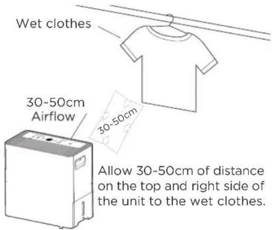
Fig. 5
4. UP AND DOWN Buttons:
Humidity Set Control Buttons
The humidity level can be set within a range of 35% RH (Relative Humidity) to 85% RH (Relative Humidity) in 5% increments.
TIMER Set Control Buttons
Press the UP and DOWN buttons to set the Auto start and Auto stop time from 00:00 to 24:00.
5. FAN SPEED Function:
Press the button to select fan speed in the following setting: Low → High —Low ...

NOTE
The fan speed indicator light illuminates under different fan speed settings.
6. DISPLAY:
The electronic display will show the ambient humidity and set humidity. When the timer function is used, the display will show the set time. If there is an error, the display will show the error code.
Error Codes:
ES/EH61 - Evaporator coil temperature sensor error. Unplug the unit and plug it back in. If the error repeats, call for service.
AS/EH60 - Room temperature sensor error. Unplug the unit and plug it back in. If the error repeats, call for service.
P2 - Bucket is full of water or bucket is not in right position. Empty the bucket and replace it in the right position.
P1 - Unit is defrosting. Allow the unit time to automatically service. The protection will clear after the unit self defrosts. (some units)
EH00 - Indoor EEPROM error. Unplug the unit and plug it back in. If error repeats, call for service. (some units)
7. PUMP Function (only for pump model):
Press the 📄 button to activate the built-in pump function. Pump Mode Indicator will be on. When using this function, the unit will automatically pump water out until the water tank is empty. The pump will stop automatically once the water tank is empty.

NOTES
- Pump drain hose must be well connected for this mode.
- Make sure the drain hose is pointed in the direction where you would like to drain the water to.
- If the pump indicator light and bucket full indicator light flash simultaneously after pressing the Pump button, the drain hose may not be installed correctly. See page 22 for instructions on how to properly install the drain hose.
More Features
AUTO SHUT OFF
The dehumidifier shuts off when the bucket is full, or when the bucket is removed or not replaced in the proper position. For some models, the fan motor will continue to run for 30 seconds.
When the Full indicator light illuminates, please empty the bucket and reinstall it correctly.
Then, wait 3 minutes before resuming operation, it cannot restart operation in the first 3 minutes. This is to protect the unit.
Operation will automatically start after 3 minutes.
CHECK FILTER FEATURE
The unit will automatically track how long the fan motor has been in use. Once the accumulated operation time reaches 250 hours, the check filter light will turn on, letting you know it is the optimal time to clean the filter. After cleaning and reinserting the filter, press and hold the FAN (reset filter) button for 3 seconds to turn the light off. This will repeat after every 250 hours of use.
AUTO-RESTART
If the unit turns off unexpectedly due to loss of power, it will restart with the previous function setting automatically when the power resumes.
REMOVING COLLECTED WATER
When Your Bucket Is Full
There are different ways to remove collected water.
natural_image
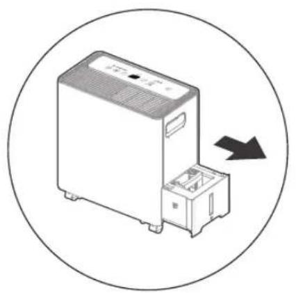
Illustration of a portable electronic device with a circular arrow indicating direction (no text or symbols)Type 1:
Bucket drainage

natural_image
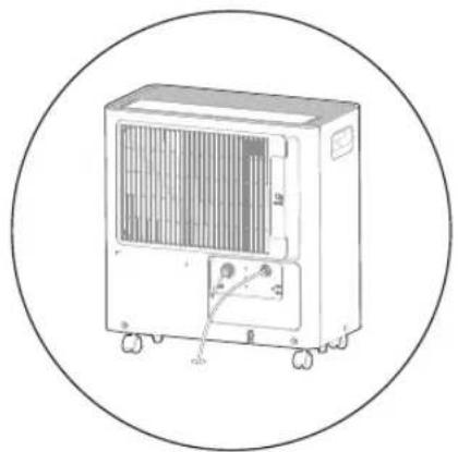
Line drawing of a portable air conditioner unit with cooling fan and cable (no text or symbols)Type 2:
Water hose drainage (continuous)
natural_image
Line drawing of a portable air conditioner unit with wheels and control panel (no text or symbols)Type 3:
Pump drainage (only for pump model)
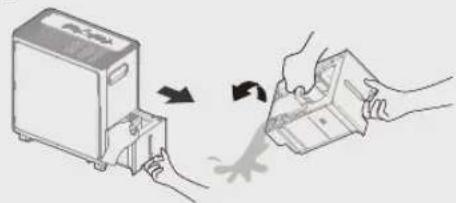
Type 1: Bucket drainage
- When the unit is off, if the bucket is full, the Full indicator light will turn on.
- When the unit is on, if the bucket is full, the comoressor and the fan turn off, and the Full indicator light will turn on, the digital display shows P2.
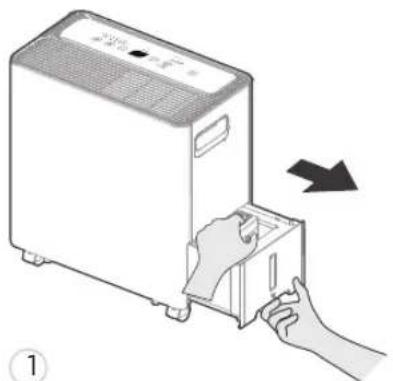
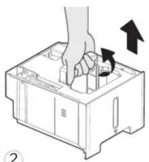
• Pull the bucket out halfway, then pull up the handle and lift the bucket slowly vertically to prevent spillage. - Dump the water and replace the bucket. The bucket must be correctly installed for the dehumidifier to operate.
• The appliance will re-start when the bucket is restored in its correct position.
natural_image
Illustration of a hand inserting a device into a container with an arrow indicating rotation (no text or symbols present)Pull the bucket out halfway.
natural_image
Diagram of a hand pressing down on a plastic container with an arrow indicating rotation (no text or symbols)Pull up the handle and lift the bucket slowly vertically.
natural_image
Illustration of hands exchanging a device with a scroll wheel (no text or symbols)3
Pour the water out.

WARNING
Do not pull out the whole bucket without grabbing the handle, or it may cause damage to the bucket or even injure you.

NOTE
- When you remove the bucket, do not touch any parts inside of the unit. Doing so may damage the product. Be sure to push the bucket gently all the way into the unit. Banging the bucket against anything or failing to push it in securely may cause the unit not to operate.
- If the pump hose becomes disconnected when you remove the bucket, you must reinstall the pump hose properly to the unit before replacing the bucket.
- When you remove the bucket, if there is some water in the unit you must dry it.
- When the unit is on, if the bucket is removed, the compressor and the fan turn off, then the unit will beep 8 times and the digital display shows Eb.
- When the unit is off, if the bucket is removed, the unit will beep 8 times and the digital display shows Eb.
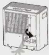
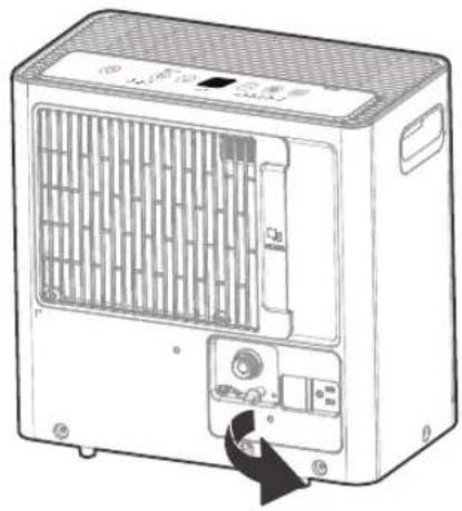
Type 2: Water Hose Drainage (continuous)
Water can be automatically emptied into a floor drain by attaching the unit with a water hose (Id ≥ ∅ 5/16", not included) with a female threaded end (ID: M=1", not included).
Before the water tank begins filling, remove the water plug from the drain outlet and set aside. Then, insert the drain hose through the water drain outlet. Lead the drain hose to the floor drain or a suitable drainage facility.
natural_image
Line drawing of a portable air conditioner unit with ventilation grilles and control panel (no text or symbols)1
Remove the water plug.
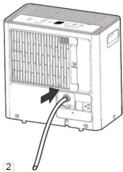
natural_image
Diagram of a portable air conditioner unit with a cable inserted, showing internal panel structure and ventilation slots (no text or symbols)Connect the drain hose.
- When you remove the water plug, if there is any water in the back drain outlet of the unit you must dry it. Make sure the hose is secure so there are no leaks and the end of the hose is level or down to let the water flow smoothly.
- Direct the hose toward the drain, making sure that there are no kinks that will stop the watowing. Make sure the water hose is lower than the drain hose outlet of the unit.
- Select the desired humidity setting and fan speed on the unit for continuous draining to start.

NOTE
When the continuous draining feature is not being used, remove the drain hose from the outlet, and dry the water in the continuous drain hose outlet. After drying, make sure to reinstall the water plug.
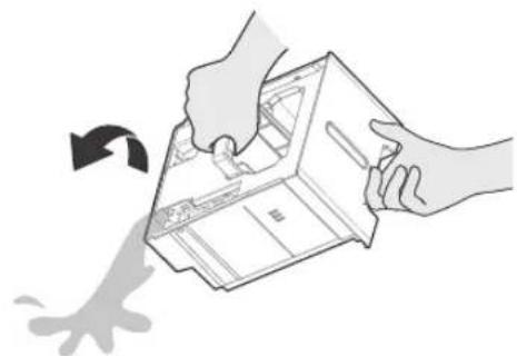
Type 3: Pump Drainage (only for pump model)
To connect pump drain hose:
- Press the tightening ring of drainage joint (as shown as Fig. 6);
- Keep pressing the grey ring while pulling out the plug. (as shown as Fig. 7);
- Insert the drain hose onto the drainage joint, make sure it is connected well so that it is fully seaed.
- Place the other end of the drain hose in the location you want the water to go to, such as a floor drain, a water container, or through a basement window to the outdoors.
To remove pump drain hose:
- Press the tightening ring of drainage joint.
• Pull out the drain hose. - Place the plug back to the joint.
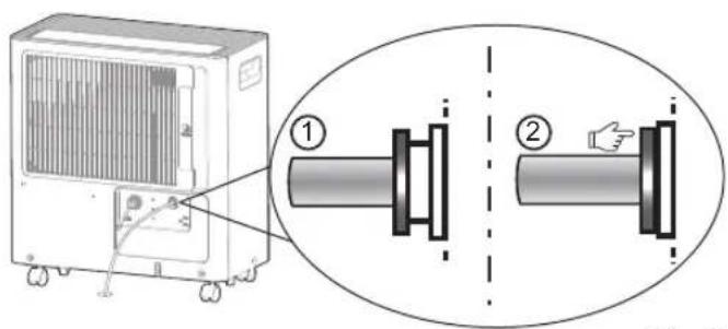
Fig. 6

Fig. 7

NOTE
- The maximum distance and the rise may be 5m from the unit. Exceeding this distance may damage the unit or cause leaks.
- If removing the hose to use in Bucket mode, please reinsert the drain plug to prevent accidental water leakage. (You still need to press the tightening ring when removing the hose.)
CLEANING AND MAINTENANCE
How To Clean & Care For Your Product
Turn the dehumidifier off and disconnect the plug from the power source before cleaning.
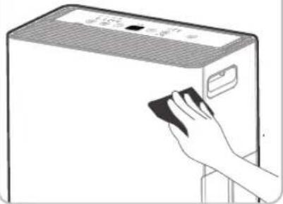
1. Clean the Grill and Case
- Use water and a mild detergent. Do not use bleach or abrasives.
- Do not splash water directly onto the unit. Doing so may cause an electrical shock, cause the insulation to deteriorate, or cause the unit to rust.
• The air intake and outlet grilles get soiled easily, so use a vacuum attachment or brush to clean.
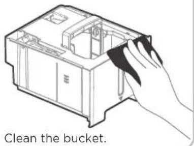
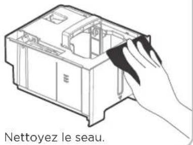
2. Clean the bucket
Every few weeks, clean the bucket to prevent growth of mold, mildew and bacteria. Partially fill the bucket with clean water and add a little mild detergent. Swish it around in the bucket, empty and rinse.

NOTE
Do not use a dishwasher to clean the bucket. After cleaning, the bucket must be in place and securely seated for the dehumidifier to operate.
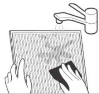
3. Clean the air filter
- To remove the filter every two weeks based on normal operating conditions.
• To remove the filter, pull filter outwards. - Wash the filter with clean water then dry.
• Re-install the filter, replace bucket.
natural_image
Illustration of a hand inserting a device into a computer tower (no text or symbols visible)Fig. 8

CAUTION
DO NOT operate the dehumidifier without a filter because dirt and lint will clog it and reduce performance
4. Clean the pump filter
- Clean the pump filter every two weeks based on normal operating conditions.
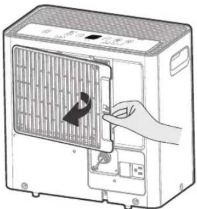
• Take out the side access tank from the unit and remove the bucket top cover. (as shown as Fig. 9) - Remove the screw as shown as Fig. 10.
• Take out the pump drainage structure and clean the filter at the button of the hose. - Reinstall the filter and pump drainage structure to the side access tank.
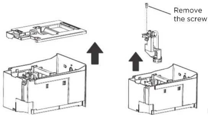
Fig. 10 Fig. 9
When Not Using The Unit For Long Time Periods
Step 1
Step 2
Step 3
Step 4
Clean the grille and case.
natural_image
Illustration of a hand cleaning a rectangular appliance with a cloth (no text or symbols visible)
natural_image
Line drawing of a rectangular electronic device with wheels and a top panel (no text or symbols)Step 5
Clean the air filter.
natural_image
Illustration of hands cleaning a surface with a hand washing it, no text or symbols presentStep 6
Step 7

Store the unit upright in a dry, well-ventilated place.
- Clean the main unit, side access tank and air filter.
- It is normal that the water tray will have a small amount of water droplets to the chassis after take out the bucket. Please dry it off.
- Wrap the cord with the power cord buckle.
• Properly restore the bucket and place the unit in an upright position.
• Cover the unit with a plastic bag. - Store the unit upright in a dry, well-ventilated place.
Malfunction Diagnosis
Before calling for service, review the chart below first. This list includes common occurrences that are not the result of defective workmanship or materials in this appliance.
Problem What to check
| Unit does not start | Make sure the dehumidifiers plug is pushed completely into the outlet. |
| Check the house fuse/circuit breaker box. | |
| Dehumidifier has reached its preset level or bucket is full. | |
| Side access tank is not in the proper position. | |
| Dehumidifier does not dry the air as it should | Did not allow enough time to remove the moisture |
| Make sure there are no curtains, blinds or furniture blocking the front or back of the dehumidifier. | |
| The humidity control may not be set low enough. | |
| Check that all doors, windows and other openings are securely closed. | |
| Room temperature is too low, below 5°C (41°F). | |
| There is a kerosene heater or something giving off water vapor in the room. | |
| The unit makes a loud noise when operating | Air filter may be dirty. Clean filter. Refer to Care and Maintenance section. |
| The unit is tilted instead of upright as it should be. | |
| The floor surface is not level. | |
| Frost appears on the coils | This is normal. The dehumidifier has an Auto defrost feature. |
| Water is leaking onto the floor | Hose to connector or hose connection may be loose. |
| Intended to use the bucket to collect water, but the back drain plug is removed. | |
| ES, AS, P2, Eb appear in the display | These are error codes and protection codes. See the CONTROL PANEL FEATURES section. |
| The pump operation on light blinks at 1 Hz | Clean the filter of the pump. |
| Check the pump hose is not blocked or leaking. | |
| Empty the side access tank. |
The design and specifications are subject to change without prior notice for product improvement. Consult with the sales agency or manufacturer for details. Any updates to the manual will be uploaded to the service website, please check for the latest version.
Dehumidifier Limited Warranty
Your product is protected by this Limited Warranty:
Warranty service must be obtained from Midea Consumer Services or an authorized Midea servicer.
Warranty
• One year full warranty from original purchase date.
Midea, through its authorized servicers will:
- Pay all costs for repairing or replacing parts of this appliance which prove to be defective in materials or workmanship.
Consumer will be responsible for:
• Diagnostics, removal, transportation and reinstallation cost required because of service.
• Costs of service calls that are a result of items listed under NORMAL RESPONSABILITIES OF THE CONSUMER**
Midea replacement parts shall be used and will be warranted only for the original warranty.
NORMAL RESPONSABILITIES OF THE CONSUMER\*\*
This warranty applies only to products in ordinary household use, and the consumer is responsible for the items listed below:
- Proper use of the appliance in accordance with instructions provided with the product.
- Routine maintenance and cleaning necessary to keep the good working condition.
- Proper installation by an authorized service professional in accordance with instructions provided with the appliance and in accordance with all local plumbing, electrical and/or gas codes.
- Proper connection to a grounded power supply of sufficient voltage, replacement of blown fuses, repair of loosen connections or defects in house wiring.
- Expenses for making the appliance accessible for servicing.
- Damages to finish after installation.
EXCLUSIONS
This warranty does not cover the following:
1) Failure caused by damage to the unit while in your possession (other than damage caused by defect or malfunction), by its improper installation, or by unreasonable use of the unit, including without limitation, failure to provide reasonable and necessary maintenance or to follow the written installation and Operating Instructions.
2) Damages caused by serviced performed by persons other than those authorized by Midea customer service; or external causes such as abuse, misuse, inadequate power supply or acts of God.
3) If the unit is put to commercial, business, rental, or other use or application other than for consumer use, we make no warranties, express or implied, including but not limited to, any implied warranty of merchantability or fitness for use or purpose.
4) Products without original serial numbers or products that have serial numbers which have been altered or cannot be readily determined.
NOTICE: Some states do not allow the exclusions or limitation of incidental or consequential damages. So this limitation or exclusion may not apply to you.
IF YOU NEED SERVICE
Keep your bill of sale, delivery slip, or some other appropriate payment Record.
The date on the bill establishes the warranty period, should service be required.
If service is performed, its your best interest to obtain and keep all receipts.
This written warranty gives you specific legal rights. You may also have other rights that vary from state to state.
Service under this warranty must be obtained by following these steps, in order:
1) Contact Midea Consumer Services or an authorized Midea services at 1-888-365-2230.
2) If there is a question as to where to obtain service, contact our consumer relations Department.

make yourself at home

www.midea.com
© Midea 2024 all rights reserved
MADSW
16120300A34247
natural_image
Line drawing of a portable air purifier with control panel and wheels (no text or symbols)Déshumidificateur
MAD
MANUEL D'UTILISATION
MDA22C4WWCM
MADA35R5AWT
MADA50R5AWT
INSTALLATION DU PRODUIT ....14
APPRENEZ À CONNAÎTRE VOS FONCTIONNALITÉS ......17
RETRAIT DE L'EAU COLLECTÉE ......21
NETTOYAGE ET ENTRETIEN 24
CONSEILS DE DÉPANNAGE 26
GARANTIE....27
Lisez ce manuel
INSTALLATION DU PRODUIT
natural_image
Line drawing of a computer tower with a hand inserting a small component into the base (no text or symbols)natural_image
Technical line drawing of a mechanical device casing with internal components and a rotation arrow (no text or symbols)3
natural_image
Simple line drawing of four roundles with no text or symbolsnatural_image
Line drawing of a rectangular electronic device with ventilation slots and mounting feet (no text or symbols)natural_image
Illustration of hands using a device to process a machine or printer (no text or symbols present)Étape 2
APPRENEZ À CONNAÎTRE VOS FONCTIONNALITÉS
natural_image
Illustration of a portable electronic device with a black arrow indicating direction (no text or symbols)natural_image
Line drawing of a portable air conditioner unit with cooling fan and cable (no text or symbols)natural_image
Line drawing of a portable air conditioner unit with wheels and control panel (no text or symbols)natural_image
Illustration of a hand inserting a device into a container with an arrow indicating rotation (no text or symbols present)natural_image
Illustration of a hand pressing down on a plastic container with an arrow indicating rotation (no text or symbols)natural_image
Illustration of hands exchanging a device with a scroll wheel (no text or symbols)3
Vider l'eau.

WARNING
natural_image
Line drawing of a portable air conditioner unit with ventilation grilles and control panel (no text or symbols)natural_image
Diagram of a portable electronic device with a cable inserted, showing internal panel structure and ports (no text or symbols)Fig. 6
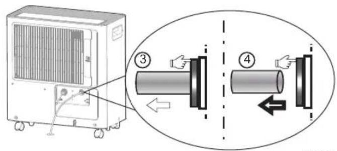
Fig. 7

REMARQUE
natural_image
Illustration of a hand inserting a device into a computer tower (no text or symbols visible)Fig. 8

ATTENTION
Fig. 10 Fig. 9
natural_image
Illustration of a hand cleaning a rectangular appliance with a cloth (no text or symbols visible)
natural_image
Line drawing of a rectangular electronic device with wheels and a top panel (no text or symbols)Étape 5
natural_image
Illustration of hands cleaning a surface with a faucet and cloth (no text or symbols)Étape 6
- USER MANUAL
- THANK YOU LETTER
- CONTENTS
- Read This Manual
- CAUTION
- SAFETY PRECAUTIONS
- Explanation of Symbols
- WARNING
- WARNING:
- SAFETY MANUAL
- CAUTION:
- Flammable
- Cabling
- Detection of flammable refrigerants
- Removal and evacuation
- Charging procedures
- Decommissioning
- Labelling
- Recovery
- GET TO KNOW YOUR PRODUCT
- Identification of Parts
- NOTE
- Accessories
- Positioning the Unit
- When Using Your Product
- Preparations for product use
- Caster installation
- GET TO KNOW YOUR FEATURES
- Control Panel Features
- Operation Display
- POWER ON/OFF Button:
- TIMER Function:
- Auto start setting
- Auto stop setting
- MODE Function:
- Set Dehumidifying mode (Set)
- Continuous Dehumidifying Mode (Cont.)
- Comfort Dehumidifying Mode - optional
- Dryer mode (Dryer) - optional
- UP AND DOWN Buttons:
- Humidity Set Control Buttons
- TIMER Set Control Buttons
- FAN SPEED Function:
- DISPLAY:
- Error Codes:
- PUMP Function (only for pump model):
- NOTES
- More Features
- AUTO SHUT OFF
- CHECK FILTER FEATURE
- AUTO-RESTART
- REMOVING COLLECTED WATER
- When Your Bucket Is Full
- Type 1: Bucket drainage
- Type 2: Water Hose Drainage (continuous)
- Type 3: Pump Drainage (only for pump model)
- To connect pump drain hose:
- To remove pump drain hose:
- CLEANING AND MAINTENANCE
- How To Clean & Care For Your Product
- Clean the Grill and Case
- Clean the bucket
- Clean the air filter
- Clean the pump filter
- When Not Using The Unit For Long Time Periods
- Malfunction Diagnosis
- Dehumidifier Limited Warranty
- Warranty
- Midea, through its authorized servicers will:
- Consumer will be responsible for:
- NORMAL RESPONSABILITIES OF THE CONSUMER\*\*
- This warranty applies only to products in ordinary household use, and the consumer is responsible for the items listed below:
- EXCLUSIONS
- This warranty does not cover the following:
- IF YOU NEED SERVICE
- MANUEL D'UTILISATION
- Lisez ce manuel
- INSTALLATION DU PRODUIT
- APPRENEZ À CONNAÎTRE VOS FONCTIONNALITÉS
- REMARQUE
- ATTENTION
Brand : MIDEA
Model : MADA50R5AWT
Category : Dehumidifier