YFB1001W - Safety gate Vevor - Free user manual and instructions
Find the device manual for free YFB1001W Vevor in PDF.


User questions about YFB1001W Vevor
0 question about this device. Answer the ones you know or ask your own.
Ask a new question about this device
Download the instructions for your Safety gate in PDF format for free! Find your manual YFB1001W - Vevor and take your electronic device back in hand. On this page are published all the documents necessary for the use of your device. YFB1001W by Vevor.
USER MANUAL YFB1001W Vevor
Technical Support and E-Warranty Certificate www.vevor.com/support
Safety gate
YFB1001W、YFB1001B
We continue to be committed to provide you tools with competitive price.
"Save Half", "Half Price" or any other similar expressions used by us only represents estimate of savings you might benefit from buying certain tools with us compared to the brands and does not necessarily mean to cover all categories of tools offered by us. Y kindly reminded to verify carefully when you are placing an order with us if you are actual half in comparison with the top major brands.
natural_image
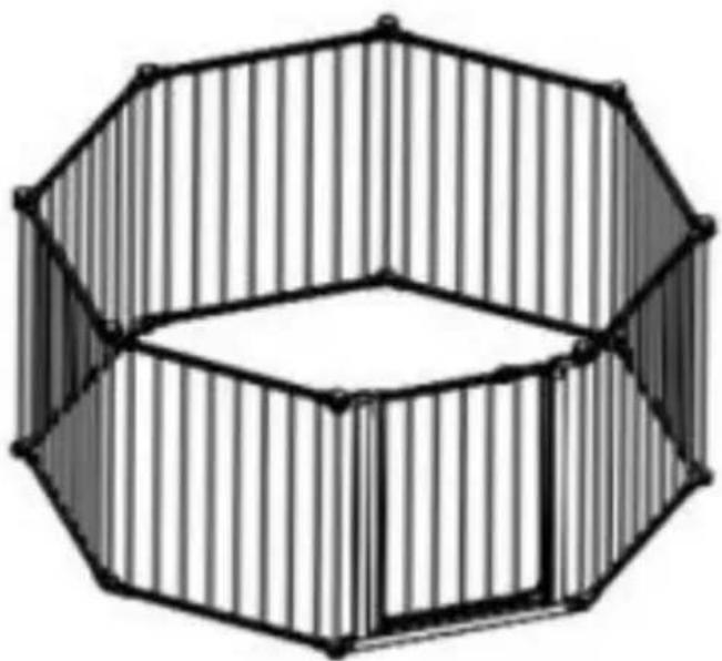
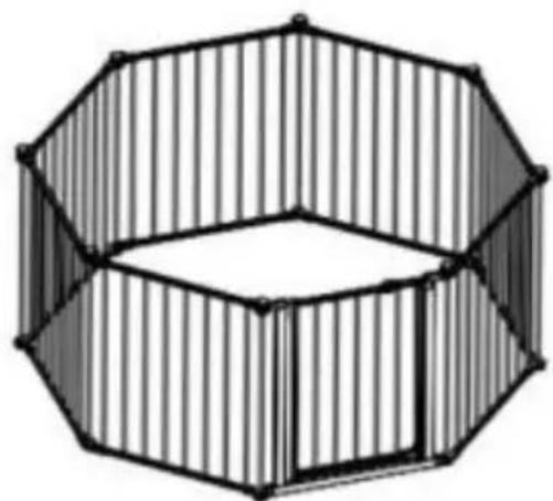
Geometric 3D diagram of a hexagonal prism with vertical striped edges (no text or symbols)Model: YFB1001W、YFB1001B
NEED HELP? CONTACT US!
Have product questions? Need technical support? Please feel free to contact Technical Support and E-Warranty Certificate www.vevor.com/support
This is the original instruction, please read all manual instructions carefully be operating. VEVOR reserves a clear interpretation of our user manual. The appearance of the product shall be subject to the product you received. Please forgive us that we won't inform you again if there are any technology or soi updates on our product.
INSTRUCTIONS
Thank you very much for choosing this dog gate .
Please read all of the instructions before using it.
The information will help you achieve the best possible results.
Model and Parameters
| Model | YFB1001W | YFB1001B |
| Width | 192inch (487.7cm) | |
| Height | 28inch (71.1cm) | |
| Colour | White | Black |
ASSEMBLY AND USE
- Component Diagram Please check to make sure you have the following parts
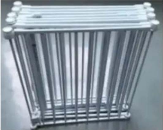 | 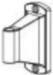 |  |
| A. Gate Frame Assembly | B. Plastic Mounting Brackets *4 | C. 1"Screws *8 |
- Read and follow all instructions carefully to ensure that your install is proper. Improper installation could result in the fence becoming uns
or cause the fence to detach. Always make sure the extensions secure attached to the fence before using. The safety of your child is your responsibility.
- The four mounting brackets must be used in securing the fence to wall. These brackets prevent the fence from dislodging from its opening and becoming unstable. The maximum width of this fence is 192 inch.
- Periodically check the fence for signs of damage, wear, or missing components. Do not use if any part is missing, worn or damaged.
Option A: Installing Your Gate Between Two Walls
- Unfold the gate frame by turning the locking knobs counter clockw at each pivoting joint. Loosen the knobs enough to allow the gate to open freely without fully removing the knobs.
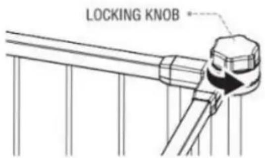
text_image
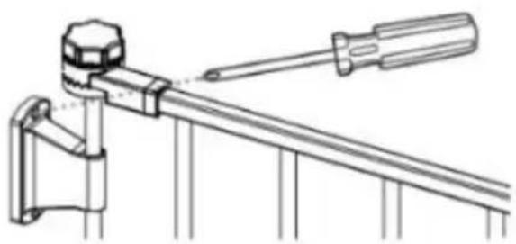
LOCKING KNOB- Use a screwdriver to attach the plastic mounting brackets to a su with the specified width, and it also mentions the recommended instal height as illustrated in a diagram.
The recommended installation height for the brackets is as illustrated diagram.
natural_image
Technical line drawing of a mechanical lever assembly (no text or symbols)- Arrange the gate frame to your desired configuration, then tighten the locking knobs.
Note: This gate is designed to fit openings 51.5 inches to 192 inches
Option B: Gate Frames Can Be Installed As A Fence
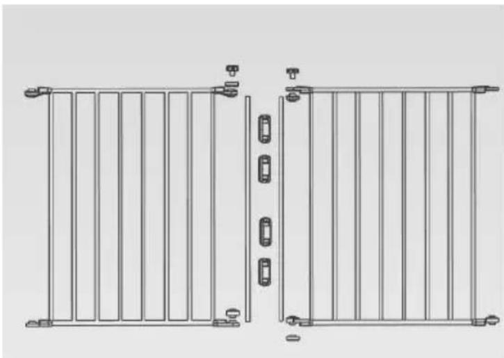
- Unfold the gate frame by turning the locking knobs counter clockw each pivoting joint. Loosen the knobs enough to allow the gate to sv open freely without fully removing the knobs, Release the vertical met pivot bars at each gate frame by removing the following parts from t assembly.
natural_image
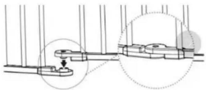
Technical line drawing of two vertical metal frame structures with mounting feet and side lockers (no text or symbols)- Position the play yard into your desired configuration (e.g. octagon, square), then join the free ends of the play yard together at the pla joints.
natural_image
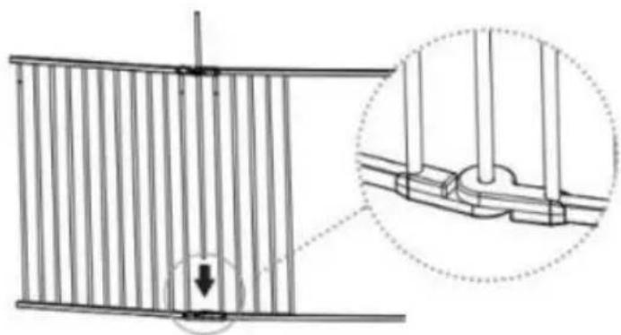
Technical line drawing of a mechanical assembly with two circular insets showing close-up views (no text or symbols)- Insert one of the previously removed metal pivot bars through the opening created by joining the upper plastic joints. Guide the metal p bar downward into the circular housing on the lower plastic joint.
natural_image
Technical diagram showing a structural connection with an inset close-up of a bracket detail (no text or symbols)- Reassemble the upper locking joint by adding one of the previously removed toothed disks and locking knobs.

natural_image
Mechanical assembly diagram showing gear and shaft components with a magnified inset (no text or labels)- Tighten each of the locking knobs by turning them clockwise, fixing fence into the configuration you have chosen. To position the fence in new configuration or shape, simply loosen each of the locking knobs, adjust and retighten.
NOTE: When adding or removing additional panel units to the configu panels must be added or subtracted in sets of two for the freestandi enclosure to function properly.
natural_image
Geometric 3D diagram of a hexagonal prism with vertical striped edges (no text or symbols)Door Lock Operation
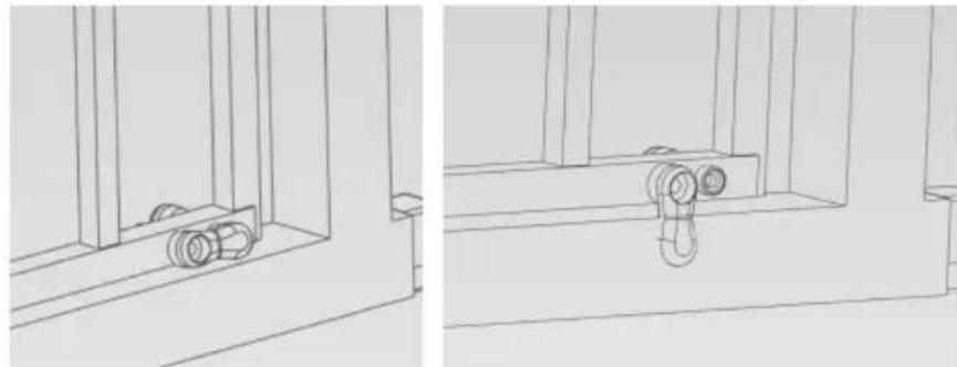
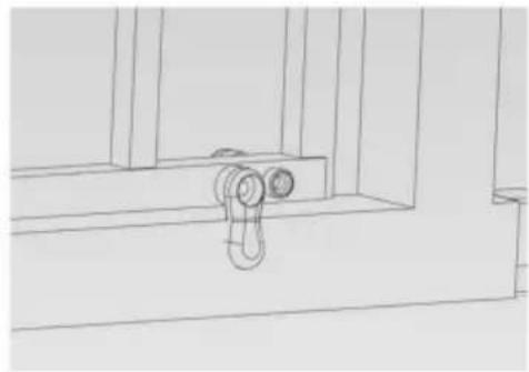
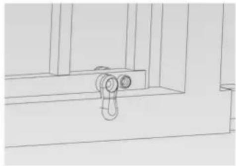
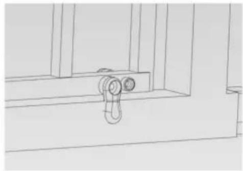
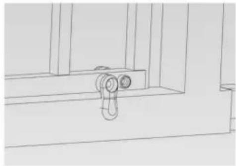
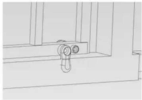
- To open the gate, start with rotating the base lock in the upward direction. You can rotate the base lock in either direction.
natural_image
Technical line drawing of two mechanical components with mounting brackets and a hanging hook (no text or symbols)Unlocked Locked
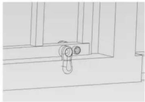
- Pull both sides of the slide lock sideways away from the metal lift while simultaneously pivoting the metal lift latch upward from the gate's door frame. To relock the gate, close the door completely and drop metal lift latch back into place. The slide lock will return to it's lock position on its own.
natural_image
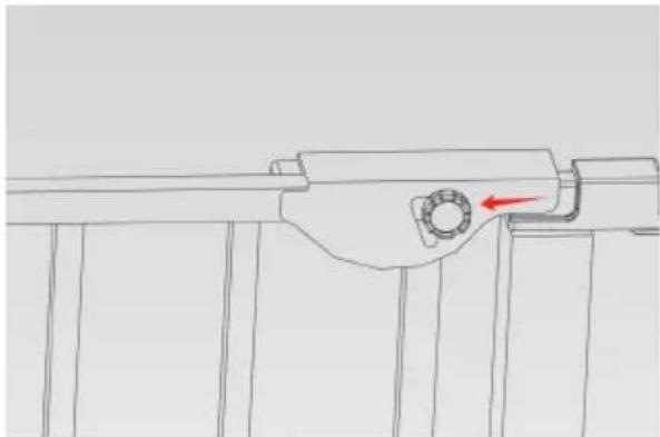
Technical line drawing of a mechanical assembly with a red arrow indicating a component (no text or symbols present)Fold the fence
- Loosen all of the locking knobs so the fence can move freely and becomes flexible at the joints.
- Remove one of the locking knobs from the fence and remove one vertical tube.
- Pull the two plastic joints and the top and bottom of the fence a
- Fold and put away.
Product & Parts
WARNING
- To prevent serious injury or death, securely install the gate or enclosure and it according to the manufacturer's instructions.
- Never use with a child able to climb over or dislodge the gate or enclo-s
- This product will not necessarily prevent all accidents.
- Never leave children unattended.
- Use only with the locking mechanism securely engaged
- Intended for use with children from 8 months through 24 months of age.
- Stop using the gate if any parts are missing or become damaged.
- Children may die or been seriously injured when gates are not securely in
- ALWAYS install and use gates as directed using all required parts.
- Periodically check all fasteners to be sure they are tight and secure.
- Adult Assembly Required.
- The surfaces that the gate is to be fixed to must be suitable for the purp must be structurally sound.
- Indoor use only. It is not to be exposed to outdoor elements.
- Install this gate away from heaters and other sources of heat.
- STOP using it when a child can climb over or dislodge the gate.
- You MUST install [wall cups] to keep the gate in place. Without [wall cups] child can push out and escape.
- NEVER use it to keep the child away from a pool.
AVERTISSEMENT !
- Thanks for purchasing VEVOR product!
VEVOR®
TOUGH TOOLS, HALF PRICE
Technical Support and E-Warranty Certificate www.vevor.com/support
VEVOR®
TOUGH TOOLS, HALF PRICE
natural_image
Geometric 3D diagram of a hexagonal prism with vertical striped pattern (no text or symbols)Modele YFB1001W, YFB1001B
POTRZEBUJESZ POMOCY? SKONTAKTUJ SIĘ Z NAMI!
natural_image
Technical line drawing of a mechanical clamp or lever assembly (no text or symbols)natural_image
Technical line drawing of two identical metal-framed outdoor gate structures with vertical dividers and mounting feet (no text or symbols)natural_image
Technical diagram showing mechanical assembly with two circular insets highlighting a detail (no text or symbols)natural_image
Technical diagram showing a structural connection with an arrow indicating downward motion, no text or symbols presentnatural_image
Mechanical assembly diagram showing gear and shaft components with a magnified inset (no text or symbols)natural_image
Geometric 3D diagram of a hexagonal prism with vertical striped edges (no text or symbols)natural_image
Technical line drawing of a mechanical assembly with cylindrical components and vertical supports (no text or symbols)Odblokowany
natural_image
Technical line drawing of a mechanical assembly with a hanging hook and mounting bracket (no text or symbols)Zamknię ty
natural_image
Technical line drawing of a mechanical component with a red arrow indicating a specific part (no text or symbols present)Złóż płot
natural_image
Geometric 3D diagram of a hexagonal prism with vertical striped pattern (no text or symbols)Modello: YFB1001W, YFB1001B
natural_image
Technical line drawing of a mechanical clamp or lever assembly (no text or symbols)natural_image
Technical line drawing of two identical metal-framed outdoor gate structures with vertical dividers and mounting feet (no text or symbols)natural_image
Technical diagram showing mechanical assembly with two circular insets highlighting a detail (no text or symbols)natural_image
Technical diagram showing a structural connection with an arrow indicating a downward force or compression point, alongside a magnified detail of the connection details (no text or symbols present)natural_image
Mechanical assembly diagram showing gear and shaft components with a magnified inset (no text or symbols)natural_image
Geometric 3D diagram of a hexagonal prism with vertical striped edges (no text or symbols)natural_image
Technical line drawing of a mechanical assembly with cylindrical components and vertical supports (no text or symbols)Sbloccato
natural_image
Line drawing of a mechanical assembly with a hanging hook and two circular components (no text or symbols)Bloccato
natural_image
Technical line drawing of a mechanical component with a red arrow indicating direction (no text or symbols)natural_image
Geometric 3D diagram of a hexagonal prism with vertical striped pattern (no text or symbols)Modelo: YFB1001W, YFB1001B
natural_image
Technical line drawing of a mechanical clamp or lever assembly (no text or symbols)natural_image
Technical line drawing of two identical metal-framed outdoor gate structures with vertical dividers and mounting feet (no text or symbols)natural_image
Technical diagram showing mechanical assembly with two circular insets highlighting a component detail (no text or symbols)natural_image
Technical diagram showing a structural connection with an arrow indicating downward motion, no text or symbols presentnatural_image
Mechanical assembly diagram showing gear and shaft components with a magnified inset (no text or symbols)natural_image
Geometric 3D diagram of a hexagonal prism with vertical striped edges (no text or symbols)natural_image
Technical line drawing of a mechanical assembly with cylindrical components and vertical supports (no text or symbols)Desbloqueado
natural_image
Technical line drawing of a mechanical assembly with a hanging hook and mounting bracket (no text or symbols)Bloqueado
natural_image
Technical line drawing of a mechanical component with a red arrow indicating a specific part (no text or symbols present)Doblar la valla
natural_image
Geometric 3D diagram of a hexagonal prism with vertical striped pattern (no text or symbols)natural_image
Technical line drawing of a mechanical clamp or lever assembly (no text or symbols)natural_image
Technical line drawing of two identical metal-framed outdoor gate structures with vertical dividers and mounting feet (no text or symbols)natural_image
Technical diagram showing mechanical assembly with two circular insets highlighting a detail (no text or symbols)natural_image
Technical diagram showing a structural connection with an arrow indicating force or direction, and a magnified inset of a bracket detail (no text or symbols present)natural_image
Mechanical assembly diagram showing gear and shaft components with a magnified inset (no text or symbols)natural_image
Geometric 3D diagram of a hexagonal prism with vertical striped edges (no text or symbols)Dörråsfunktion
natural_image
Technical line drawing of a mechanical assembly with cylindrical components and vertical supports (no text or symbols)Olåst

natural_image
Technical line drawing of a mechanical assembly with a hanging hook (no text or symbols)Låst
natural_image
Technical line drawing of a mechanical component with a red arrow indicating direction (no text or symbols)Vik staketet
natural_image
Geometric 3D diagram of a hexagonal prism with vertical striped edges (no text or symbols)Model: YFB1001WÿYFB1001B
HULP NODIG? NEEM CONTACT MET ONS OP!
natural_image
Technical line drawing of a mechanical clamp or lever assembly (no text or symbols)natural_image
Technical line drawing of two identical metal-framed outdoor gate structures with vertical dividers and mounting feet (no text or symbols)natural_image
Technical diagram showing mechanical assembly with two circular insets highlighting a detail (no text or symbols)natural_image
Technical diagram showing a structural connection with an arrow indicating a downward force or compression point, alongside a magnified detail of the connection details (no text or symbols present)natural_image
Mechanical assembly diagram showing gear and shaft components with a magnified inset (no text or symbols)natural_image
Geometric 3D diagram of a hexagonal prism with vertical striped edges (no text or symbols)Deurvergrendelingsbediening
natural_image
Technical line drawing of a mechanical assembly with cylindrical components and vertical supports (no text or symbols)Ontgrendeld
natural_image
Technical line drawing of a mechanical assembly with two hanging weights (no text or symbols)Vergrendeld
natural_image
Technical line drawing of a mechanical component with a red arrow indicating direction (no text or symbols)Vouw het hek
natural_image
Geometric 3D diagram of a hexagonal prism with vertical striped pattern (no text or symbols)natural_image
Technical line drawing of a mechanical clamp or lever assembly (no text or symbols)natural_image
Technical line drawing of two identical vertical metal frame structures with mounting feet and internal compartments (no text or symbols)natural_image
Technical diagram showing mechanical assembly with two circular insets highlighting a detail (no text or symbols)natural_image
Technical diagram showing a structural connection with an arrow indicating a downward force or compression point, alongside a magnified detail of the connection details (no text or symbols present)natural_image
Mechanical assembly diagram showing gear and shaft components with a magnified inset (no text or symbols)natural_image
Geometric 3D diagram of a hexagonal prism with vertical striped pattern (no text or symbols)natural_image
Technical line drawing of a mechanical assembly with cylindrical components and vertical supports (no text or symbols)Débloqué
natural_image
Technical line drawing of a mechanical assembly with two hanging weights (no text or symbols)Fermé
natural_image
Technical line drawing of a mechanical component with a red arrow indicating direction (no text or symbols)Plier la clôture
natural_image
Geometric 3D diagram of a hexagonal prism with vertical striped pattern (no text or symbols)natural_image
Technical line drawing of a mechanical clamp or lever assembly (no text or symbols)natural_image
Technical line drawing of two identical vertical metal frame structures with mounting feet and internal compartments (no text or symbols)natural_image
Technical diagram showing mechanical assembly with two circular insets highlighting a detail (no text or symbols)natural_image
Technical diagram showing a structural connection with an arrow indicating a downward force or compression point, alongside a magnified detail of the connection details (no text or symbols present)natural_image
Mechanical assembly diagram showing gear and shaft components with a magnified inset (no text or symbols)natural_image
Geometric 3D diagram of a hexagonal prism with vertical striped pattern (no text or symbols)Türschlossbetrieb
natural_image
Technical line drawing of a mechanical assembly with cylindrical components and vertical supports (no text or symbols)Freigeschaltet
natural_image
Technical line drawing of a mechanical assembly with two hanging weights (no text or symbols)Gesperrt