KLFD-03 - Office Vevor - Free user manual and instructions
Find the device manual for free KLFD-03 Vevor in PDF.

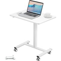
| Product Type | Reception Desk |
| Brand | Vevor |
| Model | KLFD-03 |
| Dimensions (L x D x H) | 1200 x 480 x 1100 mm |
| Maximum Load Capacity | 70 kg |
| Color | Black |
| Intended Use | Reception or welcome desk, flat and stable surface |
| Recommended Mounting Surface | Flat, level, hard and smooth |
| Main Safety Warning | Do not sit or stand on the desk |
| Recommended Personal Protective Equipment during Assembly | ANSI-approved safety glasses and sturdy work gloves |
| Inspection Before Use | Check that all parts are tightened and undamaged |
| Assembly Instructions | Follow the instructions in the manual; assemble only as directed |
| Cleaning and Maintenance | Wipe with a soft, dry cloth; avoid abrasive products |
| Warranty | Electronic warranty certificate available at www.vevor.com/support |
| Technical Support | www.vevor.com/support |
| Manufacturer | Shanghaimuxinmuyeyouxiangongsi, Shanghai, China |
| Importer United States | Sanven Technology Ltd, Rancho Cucamonga, CA |
| Importer Australia | SIHAO PTY LTD, Eastwood NSW |
| CE Representative | E-CrossStu GmbH, Frankfurt am Main |
| UK Representative | YH CONSULTING LIMITED |
| Safety Advice for Children | Do not allow children to play with or near the desk |
Frequently Asked Questions - KLFD-03 Vevor
User questions about KLFD-03 Vevor
0 question about this device. Answer the ones you know or ask your own.
Ask a new question about this device
Download the instructions for your Office in PDF format for free! Find your manual KLFD-03 - Vevor and take your electronic device back in hand. On this page are published all the documents necessary for the use of your device. KLFD-03 by Vevor.
USER MANUAL KLFD-03 Vevor
Technical Support and E-Warranty Certificate www.vevor.com/support
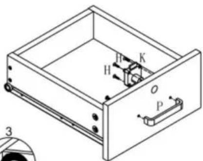
RECEPTION DESK
USER MANUAL
MODEL:KLFD-03
We continue to be committed to provide you tools with competitive price. "Save Half", "Half Price" or any other similar expressions used by us only represents an estimate of savings you might benefit from buying certain tools with us compared to the major top brands and does not necessarily mean to co all categories of tools offered by us. You are kindly reminded to verify carefully when you are placing an order with us if you are actually Saving Half in comparison with the top major brands.
VEVOR®
TOUGH TOOLS, HALF PRICE
RECEPTION DESK
MODEL:KLFD-03

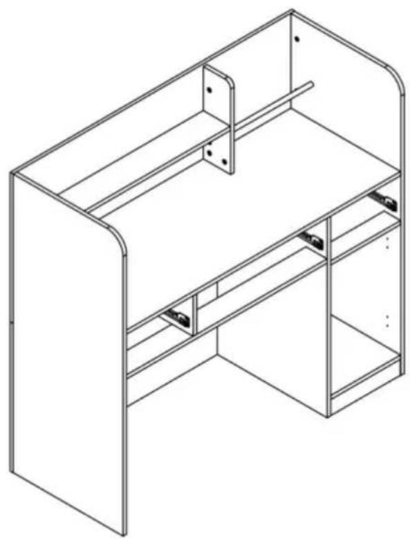
natural_image
Line drawing of a simple office desk cabinet with drawers and doors (no text or symbols)NEED HELP? CONTACT US!
Have product questions? Need technical support? Please feel free to contact us:
Technical Support and E-Warranty Certificate
www.vevor.com/support
This is the original instruction, please read all manual instructions carefully before operating. VEVOR reserves a clear interpretation of o user manual. The appearance of the product shall be subject to the product you received. Please forgive us that we won't inform you ag there are any technology or software updates on our product.
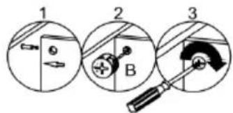
WARNING:
Read this material before using this product. Failure to do so ca result in serious injury.
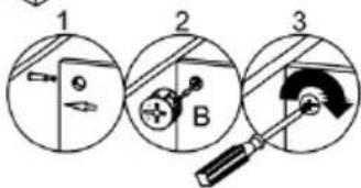
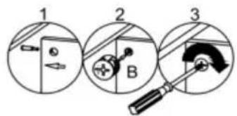
Assembly precautions
- Assemble only according to these instructions. Improper assembly c create hazards.
- Wear ANSI-approved safety goggles and heavy-duty work gloves during assembly.
- Keep the assembly area clean and well-lit.
- Keep bystanders out of the area during assembly.
- Do not assemble if tired or when under the influence of alcohol, or medication.
- The product capabilities apply to properly and completely assembled products only.
- Assemble on a flat, level, hard and smooth surface capable of sa supporting the Reception Desk.
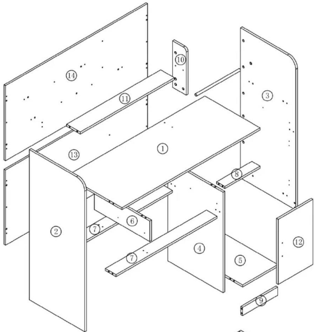
- For additional information regarding the parts listed in the following pages, please refer to the Assembly Diagram of this manual. Unw and separate all parts in a clean work area.
Use precautions
- DO NOT SIT OR STAND ON THIS ITEM.
- This product is not a toy. Do not allow children to play with or item.
- Do not exceed specified weight capacities.
- Use only on a flat, level, hard, and smooth surface that can safe support a fully loaded Reception Desk.
- Use as intended only.
- Inspect before every use; do not use if parts are loose or damage
SAVE THIS MANUAL
PARTS LIST
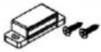
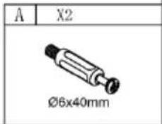
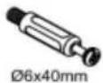
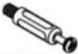
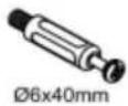
| A | x47+1 | B | x73+1 | C | x29+1 | D | x5 |
 ∅6x40mm ∅6x40mm |  ∅15x11 ∅15x11 |  ∅8x30 ∅8x30 |  ∅8x40 ∅8x40 | ||||
| E | x26+1 | F | x36+1 | G | x12 | H | x8 |
 ∅6x32mm ∅6x32mm |  M3.5x14mm M3.5x14mm |  M3.5x35mm M3.5x35mm |  M3x16mm M3x16mm | ||||
| I | x1 | J | x1 | K | x2 | L | x2 |
 M3x14mm M3x14mm |  M3x14mm M3x14mm |  |  M3x14mm M3x14mm | ||||
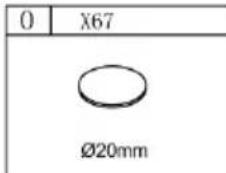
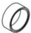
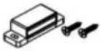
| M | x4 | N | x2 | O | x73 | P | x4 |
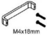
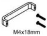
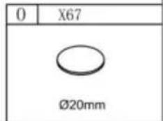
 M5x40mm M5x40mm |  |  ∅20mm ∅20mm |  M4x18mm M4x18mm | ||||
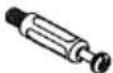
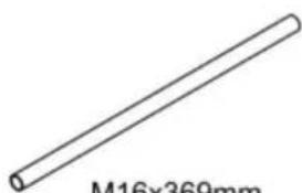
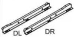
| Q | x1 | R | x3 | S | x1 | ||
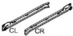
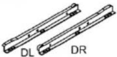
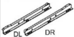
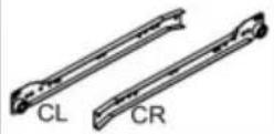
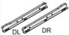
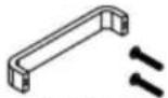
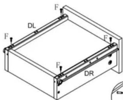
 M10X00mm M10X00mm |  CL CR DL DR CL CR DL DR |  | |||||
| T | x1 | ||||||
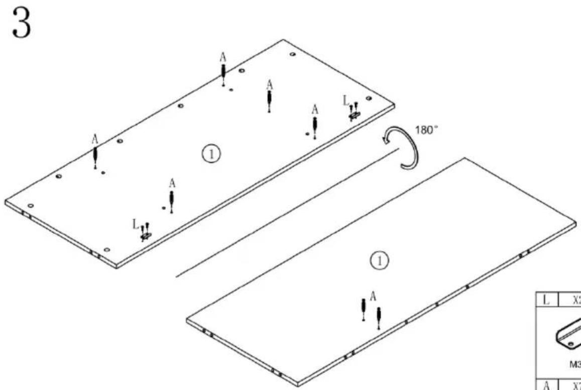
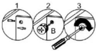
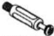
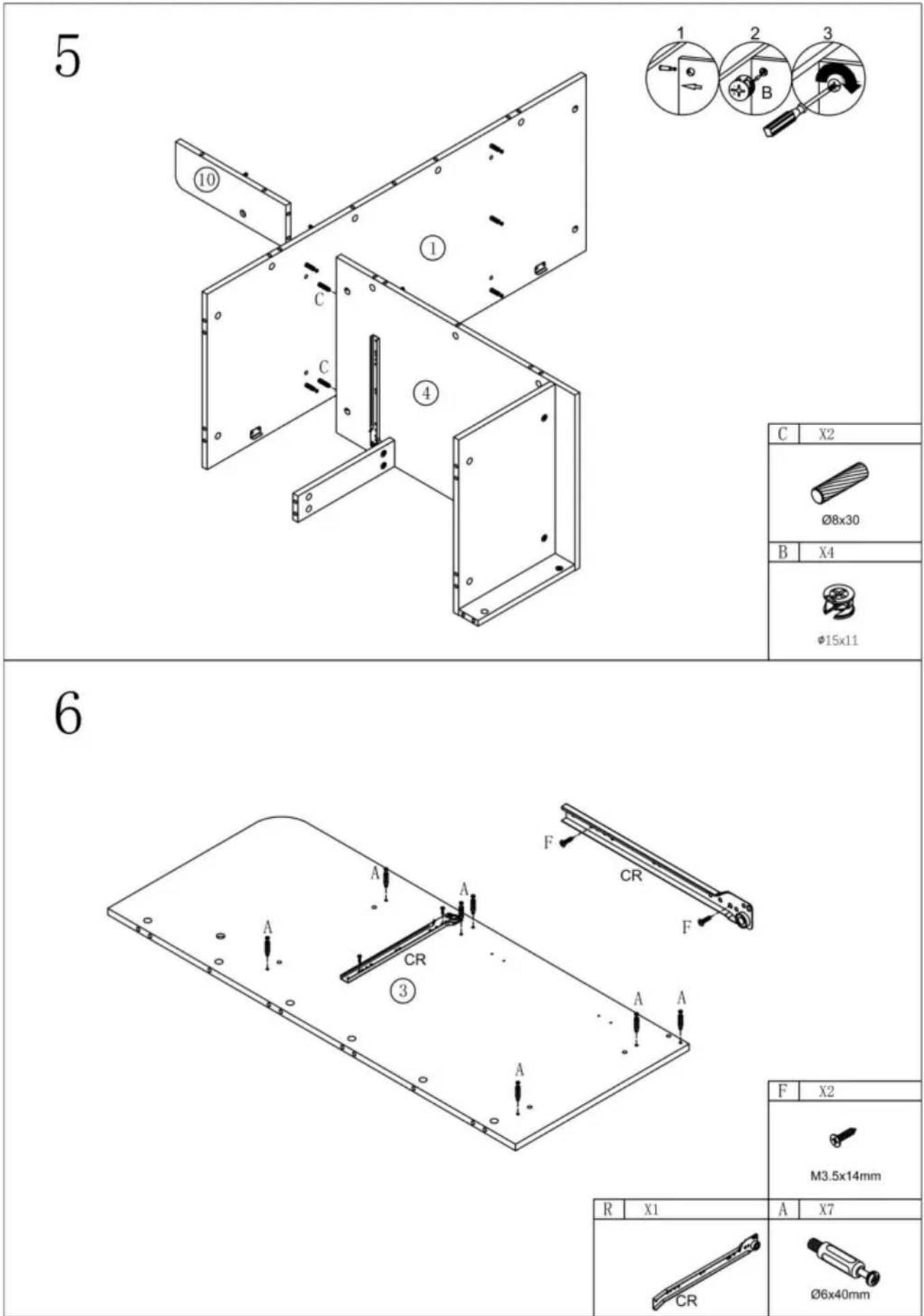
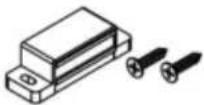
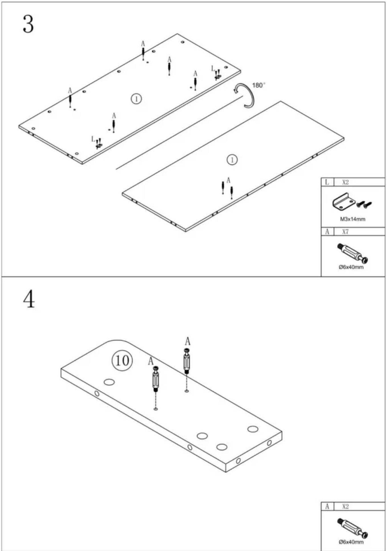
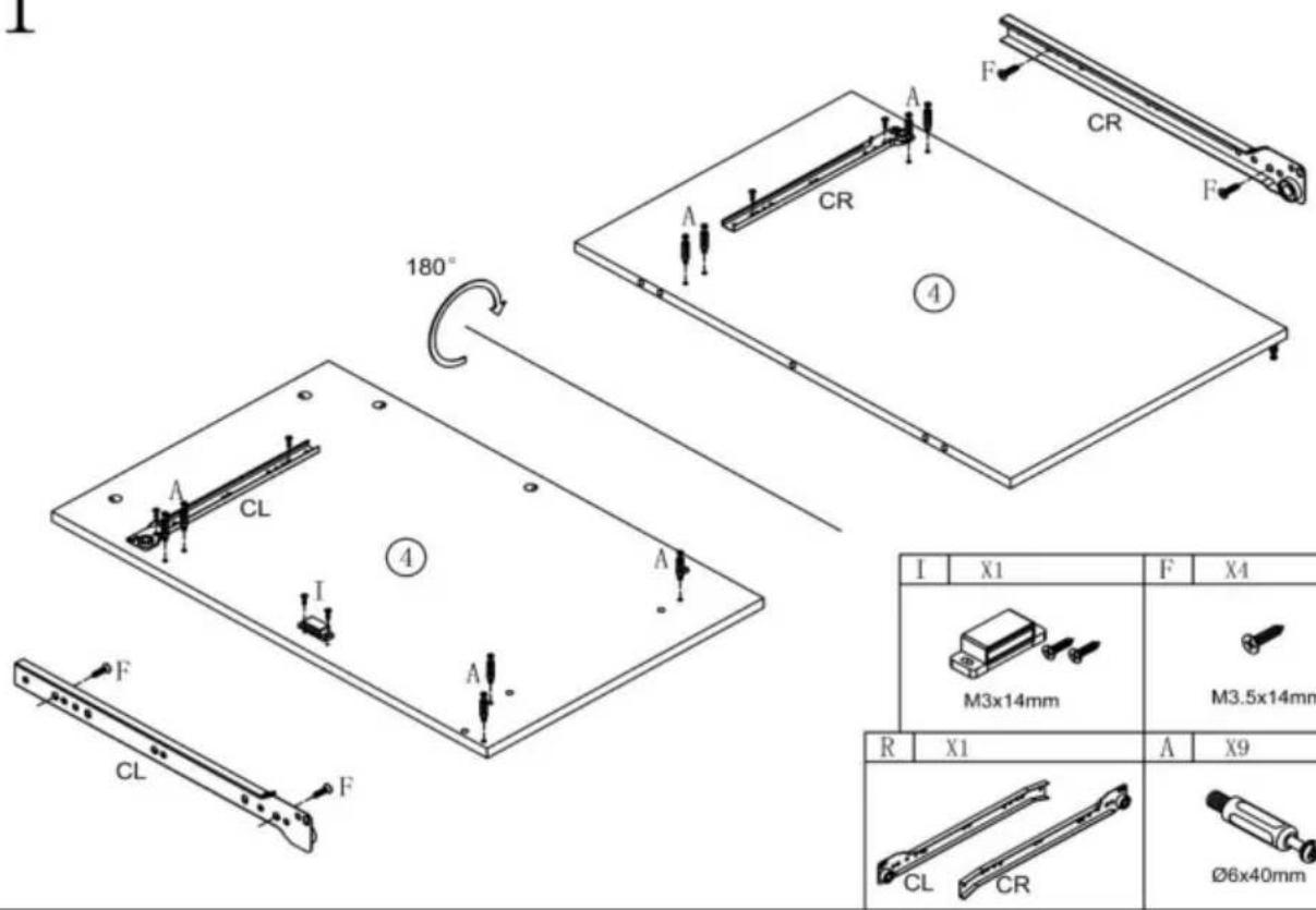
1
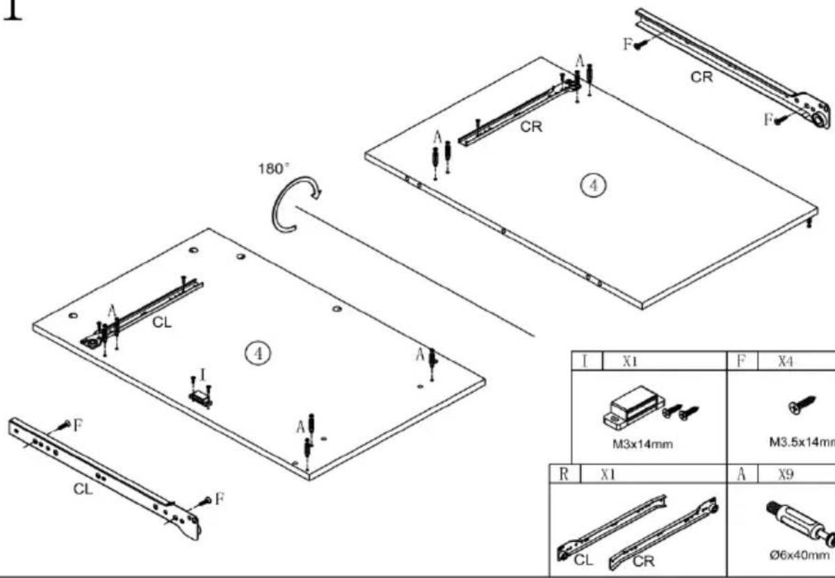
| I | X1 | F | X4 |
 M3x14mm M3x14mm | (x32T)M3.5x14mm | ||
| X1 | A | X9 | |
| R | X1 | A | X9 |
 |  6 × 40mm 6 × 40mm | ||
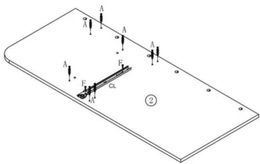
2
| C | X3 |
 ∅8x30 ∅8x30 | |
| B | X5 |
 Φ15x11 Φ15x11 | |
∅8×30
| B | X5 |
15×11
| L | X2 |
| M3x14mm | |
| A | X7 |
| Ø6x40mm | |
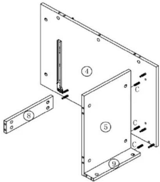
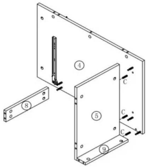
4
5
| C | X2 |
| ∅8x30 | |
| B | X4 |
| Φ15x11 | |
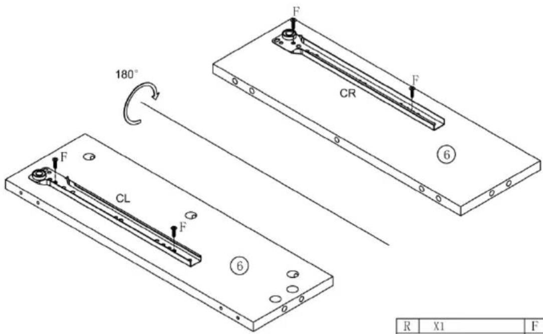
6
| F | X2 |
| M3.5x14mm | |
| A | X7 |
| Ø6x40mm | |
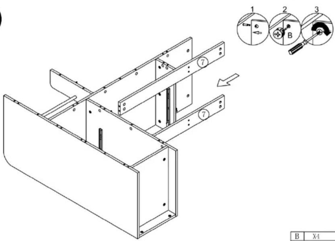
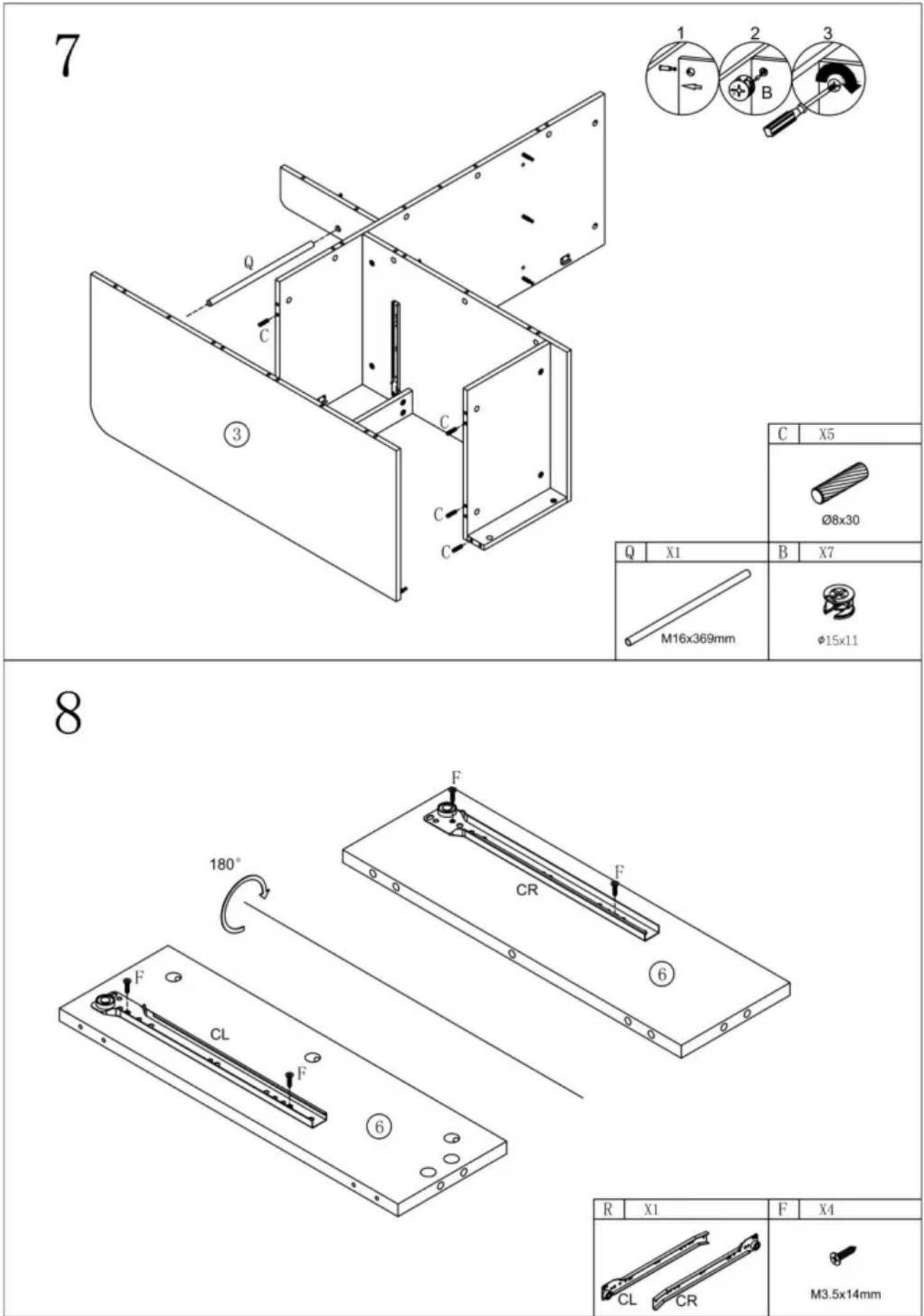
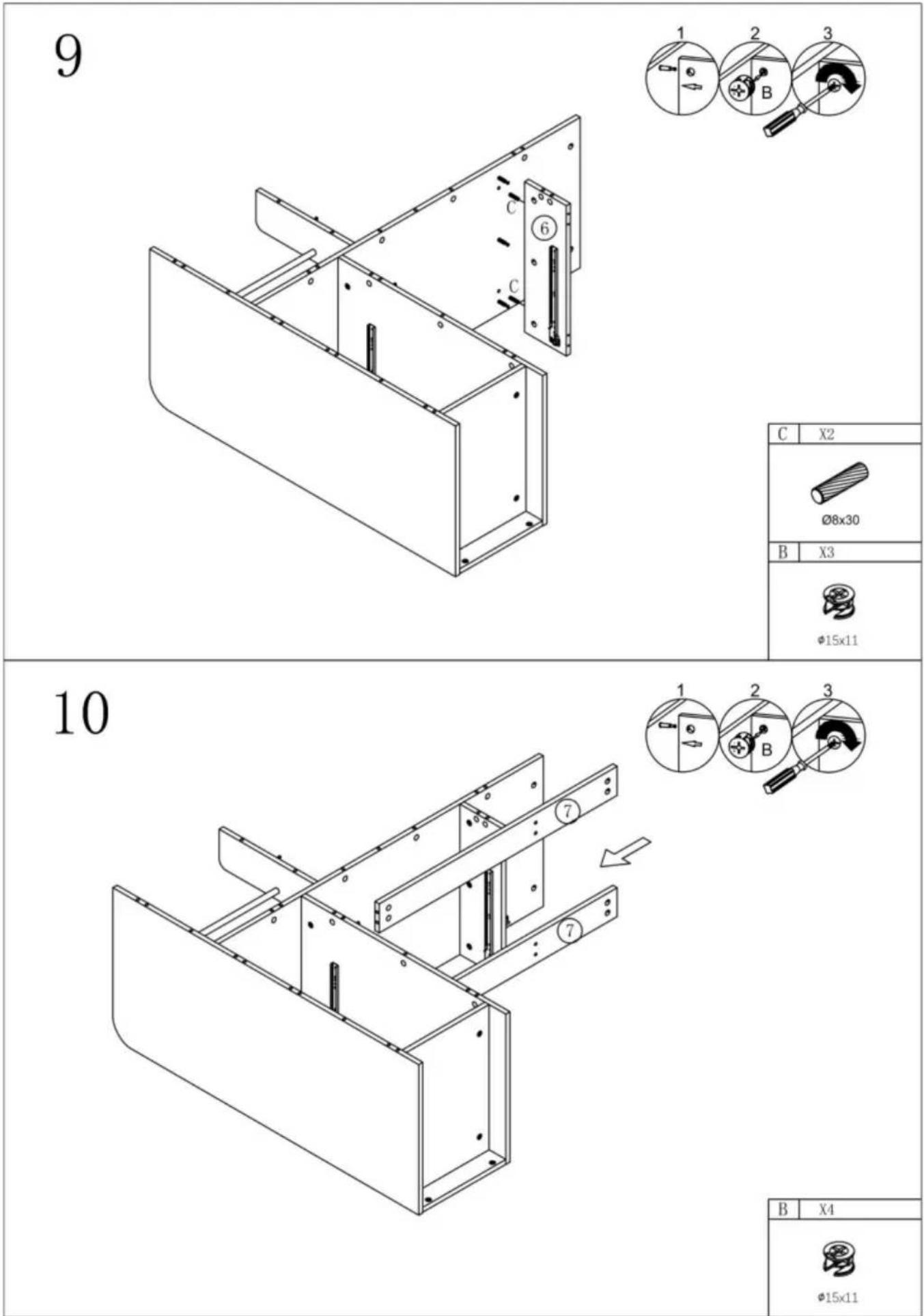
7
8
| R | X1 | F | X4 |
 | [5Kx8]M3.5x14mm | ||
9
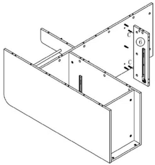
natural_image
Technical line drawing of a metal enclosure with internal components and mounting holes (no text or symbols)
| C | X2 |
| ∅8x30 | |
| B | X3 |
| Φ15x11 | |
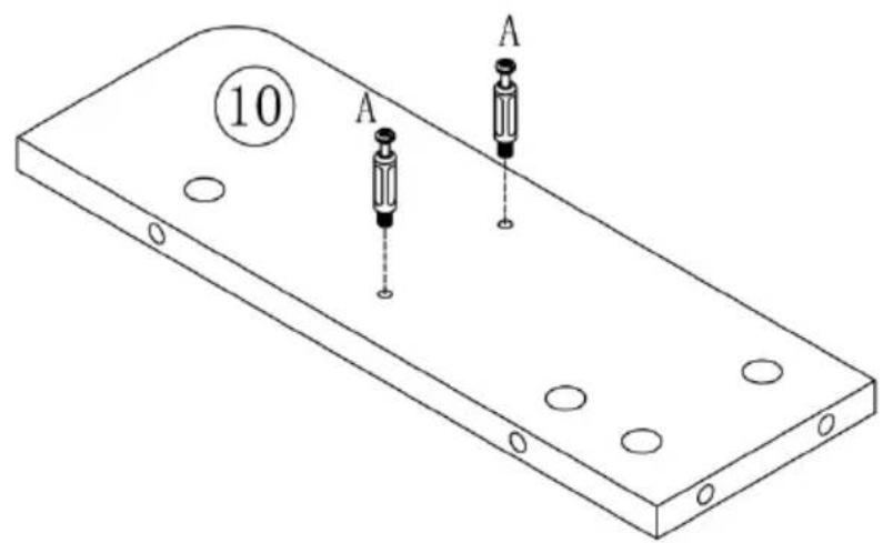
10

11
natural_image
Technical line drawing of a structural frame assembly with mounting holes and internal components (no text or symbols)
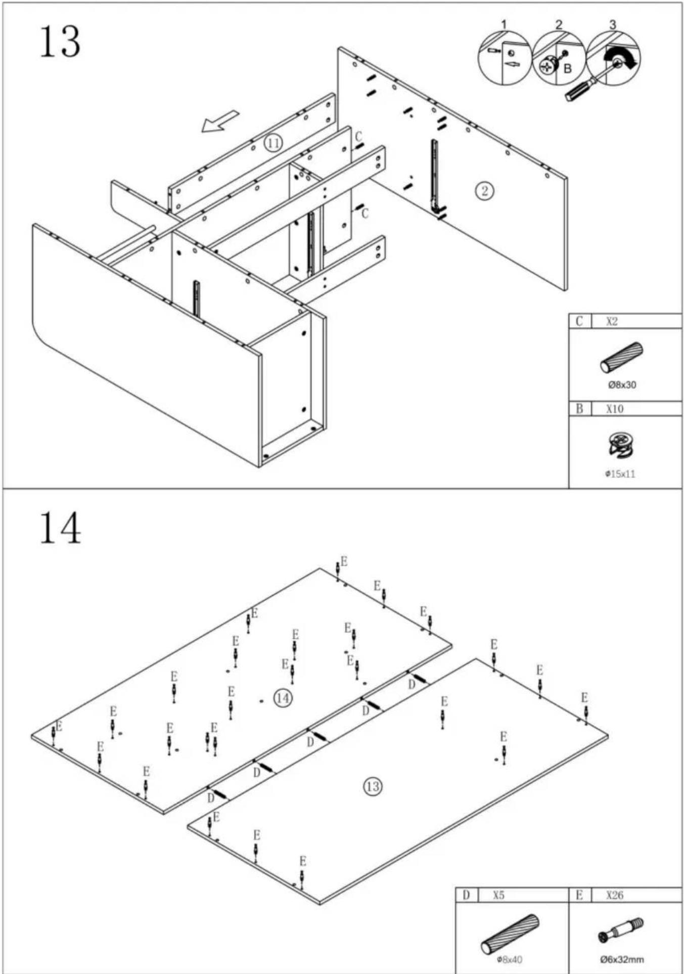
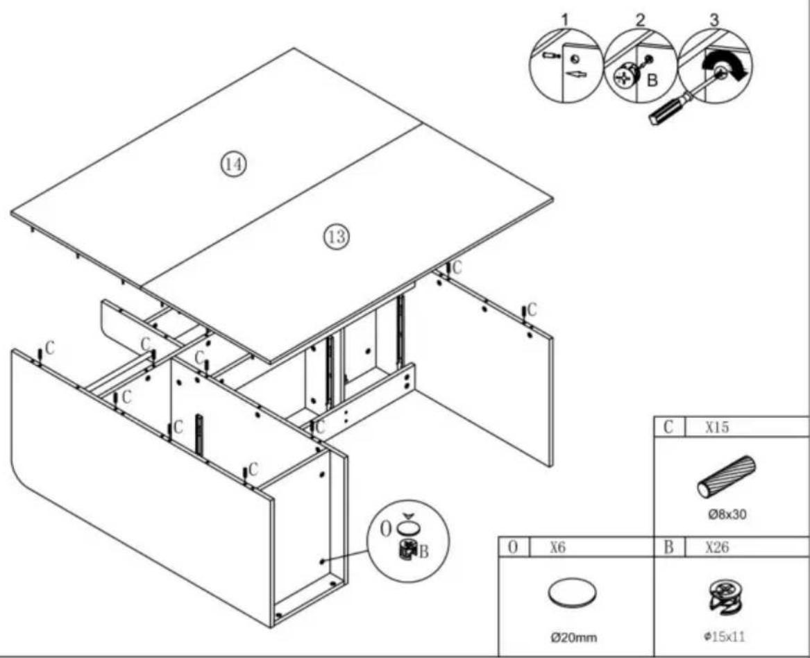
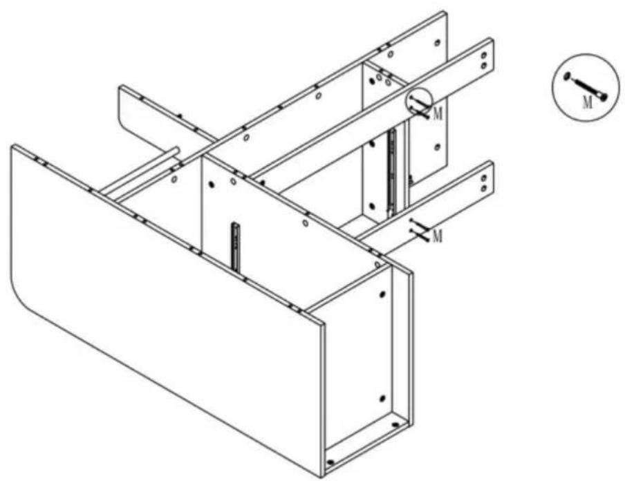
12
| F | X2 |
| M3.5x14mm | |
| A | X8 |
| Ø6x40mm | |
14
| D | X5 | E | X26 |
 Φ5x4U Φ5x4U |  Φ8x32mm Φ8x32mm |
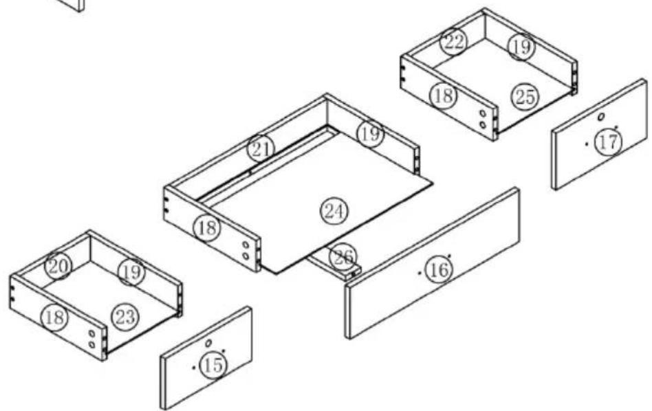
15
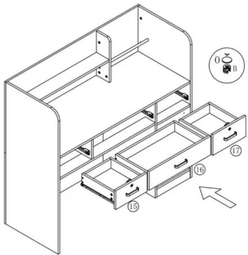
16

natural_image
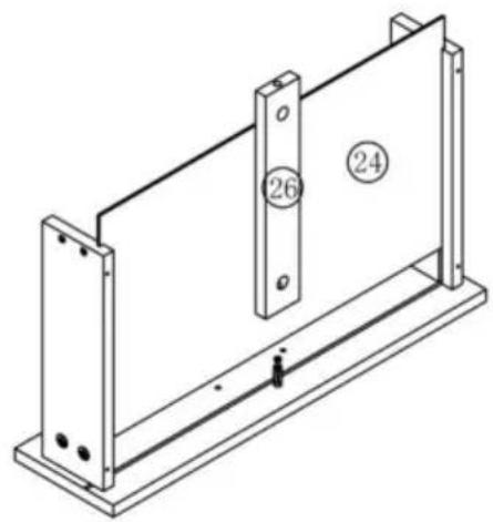
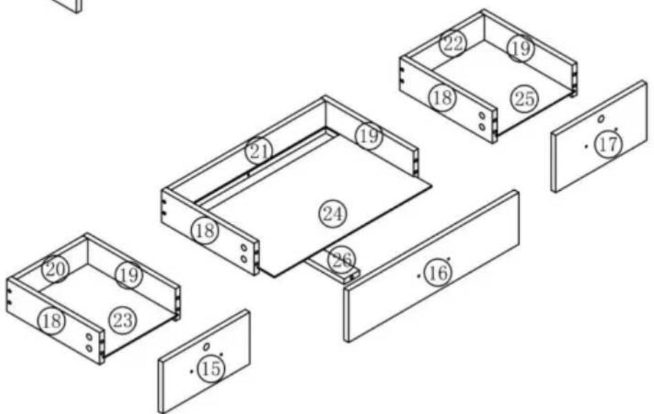
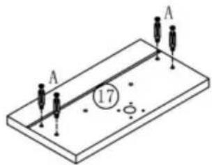
Isometric line drawing of a cabinet or enclosure structure with mounting brackets and internal compartments (no text or symbols)17

natural_image
Isometric diagram of a rectangular plate with two vertical supports and a central circular feature labeled '15' (no text or symbols beyond labels)
natural_image
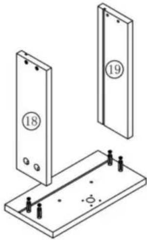
Technical line drawing of two vertical panels mounted on a base with mounting holes and a central rod (no text or symbols)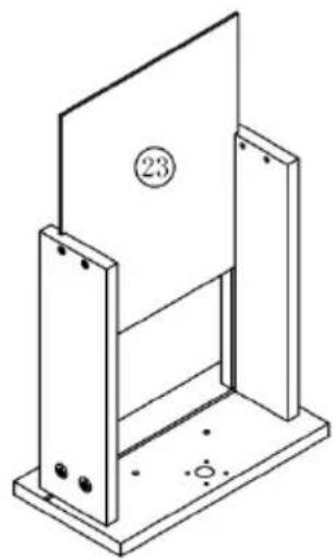
natural_image
Isometric line drawing of a mechanical assembly with a panel and base (no text or symbols)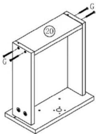
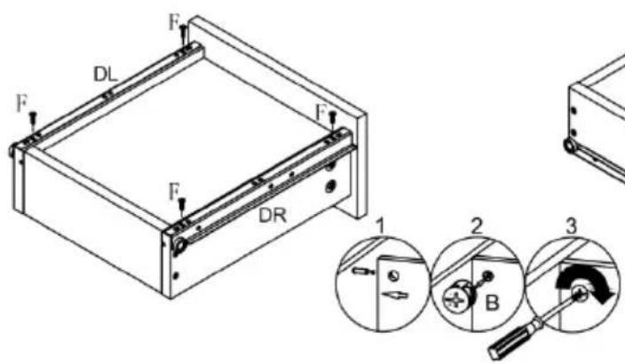
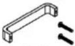
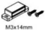
| R | X1 | P | X1 |
 |  | ||
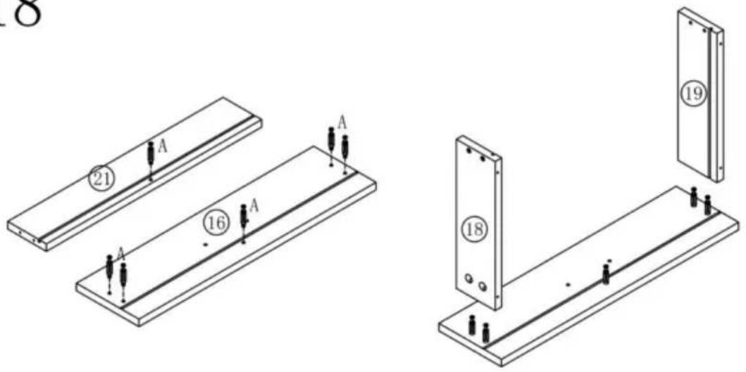
| A | X4 | B | X4 | F | X4 | G | X4 | H | X4 | K | X1 |
 ∅6x40mm ∅6x40mm |  ∅15x11 ∅15x11 |  M3.5x14mm M3.5x14mm | [20DS]M3.5x35mm |  M3x16mm M3x16mm |  | ||||||
18
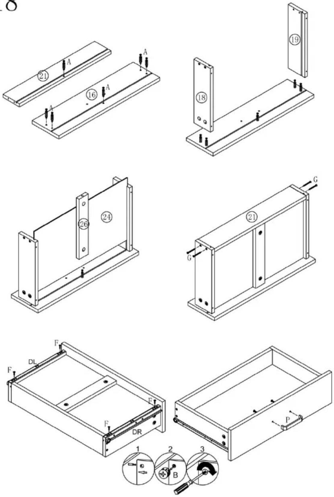
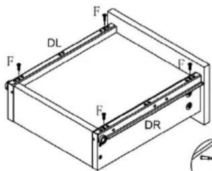
| A | X6 | B | X6 | F | X4 | G | X4 | P | X1 | R | X1 |
 ∅6x40mm ∅6x40mm |  ∅15x11 ∅15x11 | (YO4T)M3.5x14mm | (T3W6)M3.5x35mm | 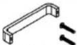 M4x18mm M4x18mm | 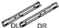 | ||||||
19

natural_image
Isometric diagram of a rectangular plate with two vertical supports and a central circular hole, marked with '17' (no text or symbols on the plate itself)
natural_image
Technical line drawing of two vertical panels mounted on a base with mounting holes and a central rod (no text or symbols)
natural_image
Isometric line drawing of a mechanical assembly with a plate and mounting base (no text or symbols)

| R | X1 | P | X1 |
 |  | ||
| A | X4 | B | X4 | F | X4 | G | X4 | H | X4 | K | X1 |
 ∅6x40mm ∅6x40mm |  ∅15x11 ∅15x11 | [G46A]M3.5x14mm | [BT8D]M3.5x35mm | [D7X5]M3x16mm |  | ||||||
20

21
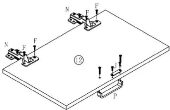
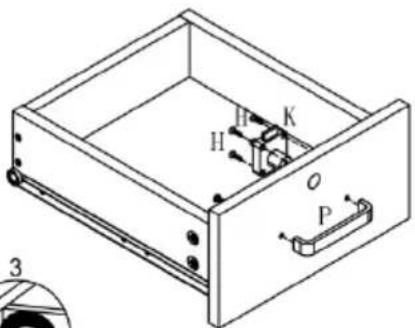
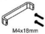
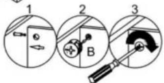
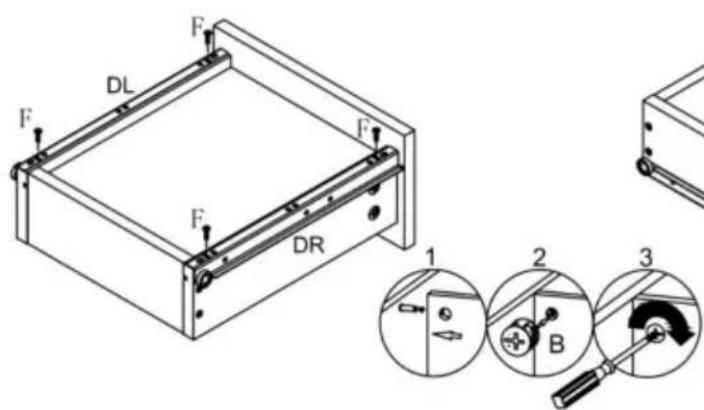
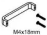
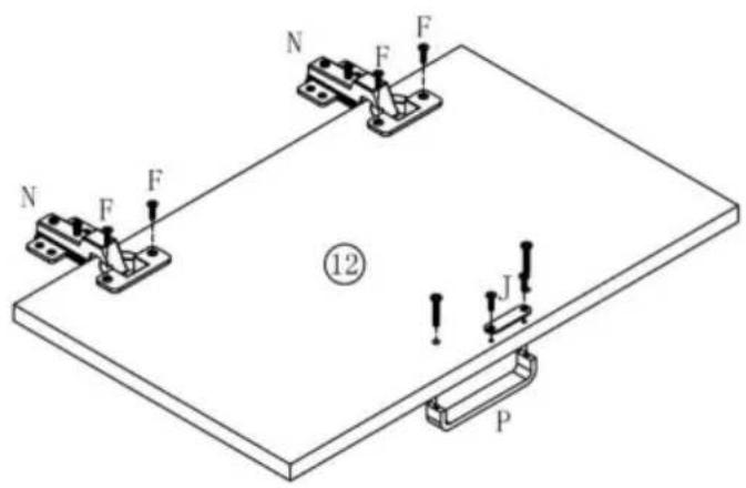
| P | X1 | N | X2 | J | X1 | F | X4 |
 M4x18mm M4x18mm | 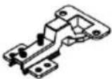 |  M3x14mm M3x14mm | [50C7]M3.5x14mm | ||||
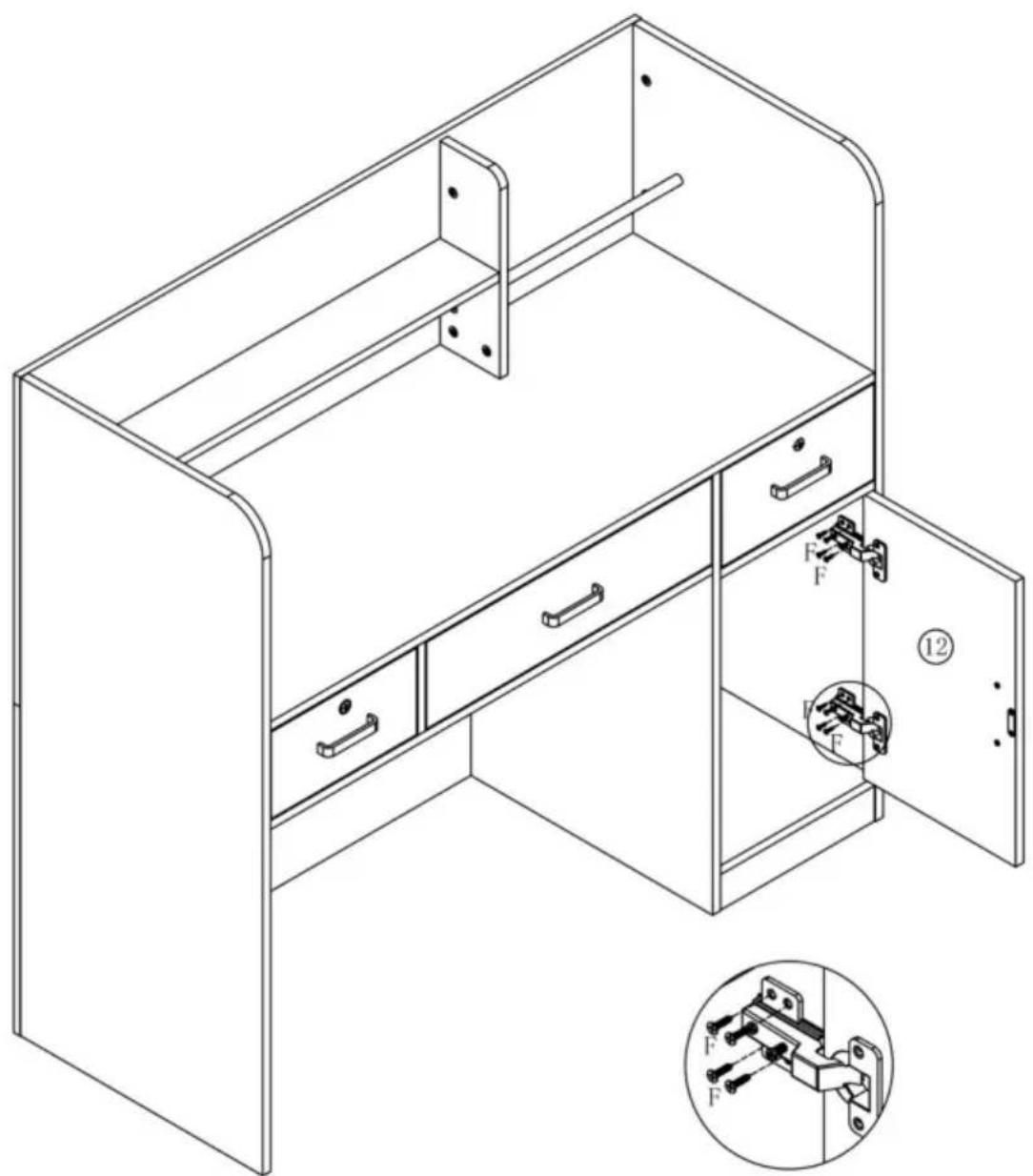
22

natural_image
Technical line drawing of a cabinet with open door and internal compartments, showing internal components (no text or symbols)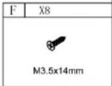
| Model | KLFD-03 |
| Safe Loading Weight | 70kg |
| Colour | Black |
| Product Size | 1200*480*1100 mm |
Manufacturer: Shanghaimuxinmuyeyouxiangongsi
Address: Shuangchenglu 803nong11hao1602A-1609shi, baoshanqu, shanghai 200000 CN.
Imported to AUS: SIHAO PTY LTD. 1 ROKEVA STREETEASTWOOD NSW 2122 Australia
Imported to USA: Sanven Technology Ltd. Suite 250, 9166 Anaheim Place, Rancho Cucamonga, CA 91730
| EC | REP |
E-CrossStu GmbH
Mainzer Landstr.69, 60329 Frankfurt am Main
| UK | REP |
YH CONSULTING LIMITED.
C/O YH Consulting Limited Office 147, Centurion House, London Road, Staines-upon-Thames, Surrey TW18 4AX
VEVOR®
TOUGH TOOLS, HALF PRICE
Technical Support and E-Warranty Certificate
www.vevor.com/support
VEVOR®
TOUGH TOOLS, HALF PRICE
natural_image
Line drawing of a simple desk cabinet with drawers and doors (no text or symbols)BESOIN D'AIDE? CONTACTEZ-NOUS!

©
ÉTAPE D'ASSEMBLAGE
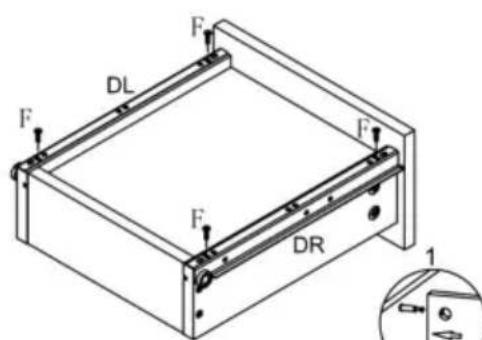
1

| I | X1 | F | X4 |
 | [0T5Y]M3.5x14mm | ||
| X1 | X9 | ||
| R | X1 | Λ | X9 |
 |  | ||
2

| C | X3 |
 ∅8x30 ∅8x30 | |
| B | X5 |
 ∅15x11 ∅15x11 | |
∅8×30
| B | X5 |
Φ15×11


11

natural_image
Technical line drawing of a structural frame assembly with mounting holes and internal components (no text or symbols)
12

| F | X2 |
| M3.5x14mm | |
| A | X8 |
| Ø6x40mm | |
15

16
natural_image
Isometric line drawing of a cabinet or enclosure structure with mounting brackets and structural supports (no text or symbols)17

natural_image
Isometric diagram of a rectangular plate with two vertical supports and a central circle labeled '15' (no text or symbols beyond labels)
natural_image
Technical diagram showing two vertical panels labeled 18 and 19 mounted on a base with mounting holes (no text or symbols beyond labels)
natural_image
Isometric line drawing of a mechanical support structure with mounting base and panel (no text or symbols)


| R | X1 | P | X1 |
 |  | ||
| A | X4 | B | X4 | F | X4 | G | X4 | H | X4 | K | X1 |
 ∅6x40mm ∅6x40mm |  Φ15x11 Φ15x11 | [XCS7]M3.5x14mm |  M3.5x35mm M3.5x35mm | [A648]M3x16mm |  | ||||||
18

natural_image
Technical line drawing of a metal frame assembly with mounting holes and a central circular component (no text or symbols)

| A | X6 | B | X6 | F | X4 | G | X4 | P | X1 | R | X1 |
 ∅6x40mm ∅6x40mm |  ∅15x11 ∅15x11 | [Y085]M3.5x14mm | [2C02]M3.5x35mm |  M4x18mm M4x18mm |  -DL-DR -DL-DR |
19

natural_image
Isometric diagram of a rectangular plate with two vertical supports and a central circle containing the number 17, no text or symbols present.
natural_image
Technical line drawing of two vertical panels mounted on a base with mounting holes and a central rod (no text or symbols)
natural_image
Isometric line drawing of a mechanical support structure with no text or symbols


| R | X1 | P | X1 |
 |  | ||
| A | X4 | B | X4 | F | X4 | G | X4 | H | X4 | K | X1 |
 ∅6x40mm ∅6x40mm |  Φ15x11 Φ15x11 | [720K]M3.5x14mm |  M3.5x35mm M3.5x35mm |  M3x16mm M3x16mm |  | ||||||
20


21

| P | X1 | N | X2 | J | X1 | F | X4 |
 M4x18mm M4x18mm | 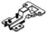 | 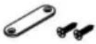 M3x14mm M3x14mm |  M3.5x14mm M3.5x14mm | ||||
22

natural_image
Technical line drawing of a cabinet with drawers and door, showing internal components and mounting bracket (no text or symbols)
PARAMÈTRE DU PRODUIT
A/S YH Consulting Limited Bureau 147, Centurion
Maison, London Road, Staines-upon-Thames, Surrey, TW18 4AX
VEVOR®
TOUGH TOOLS, HALF PRICE
natural_image
Line drawing of a simple desk cabinet with drawers and doors (no text or symbols)
| A | x47+1 | B | x73+1 | C | x29+1 | D | x5 |
 ∅6x40mm ∅6x40mm |  ∅15x11 ∅15x11 |  ∅8x30 ∅8x30 |  ∅8x40 ∅8x40 | ||||
| E | x26+1 | F | x36+1 | G | x12 | H | x8 |
 ∅6x32mm ∅6x32mm |  M3.5x14mm M3.5x14mm |  M3.5x35mm M3.5x35mm | [T2HS]M3x16mm | ||||
| I | x1 | J | x1 | K | x2 | L | x2 |
 M3x14mm M3x14mm |  M3x14mm M3x14mm |  |  M3x14mm M3x14mm | ||||
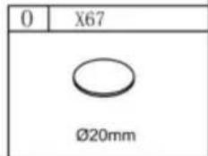
| M | x4 | N | x2 | O | x73 | P | x4 |
 M5x40mm M5x40mm |  |  ∅20mm ∅20mm |  M4x18mm M4x18mm | ||||
| Q | x1 | R | x3 | S | x1 | ||
 M10XJ05HMM M10XJ05HMM | 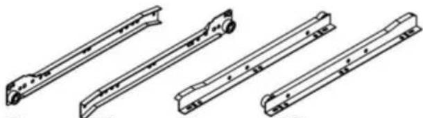 CL CR DL DR CL CR DL DR | 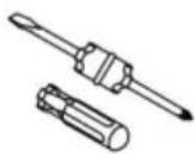 | |||||
| T | x1 | ||||||
 | |||||||
MONTAGESTRITT
1

| I | X1 | F | X4 |
| [0Y4A]M3.5x14mm | ||
| X1 | X9 | ||
| R | X1 | Λ | X9 |
|  | ||
2


| C | X3 |
| ∅8x30 | |
| B | X5 |
| Φ15x11 | |
∅8×30
| B | X5 |
| |
| 15× 11 |


11

natural_image
Technical line drawing of a structural frame assembly with mounting holes and internal components (no text or symbols)
12

| F | X2 |
| M3.5x14mm | |
| A | X8 |
| Ø6x40mm | |

15

16

natural_image
Isometric line drawing of a cabinet or enclosure structure with mounting brackets and structural supports (no text or symbols)17

natural_image
Isometric diagram of a rectangular plate with two vertical supports and a central circle labeled '15' (no text or symbols beyond labels)
natural_image
Technical line drawing of two vertical panels mounted on a base with mounting holes and a central rod (no text or symbols)
natural_image
Isometric line drawing of a mechanical support structure with no text or symbols


| R | X1 | P | X1 |
| | ||
| A | X4 | B | X4 | F | X4 | G | X4 | H | X4 | K | X1 |
| ∅6x40mm | Φ15x11 |  M3.5x14mm M3.5x14mm | M3.5x35mm |  M3x16mm M3x16mm | | ||||||
18


natural_image
Technical line drawing of a metal frame assembly with mounting holes and a central circular component (no text or symbols)
natural_image
Technical line drawing of a rectangular structural frame with labeled dimensions G and 21 (no text or symbols beyond labels)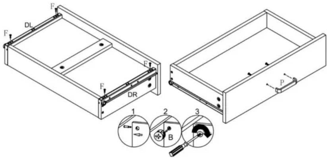
| A | X6 | B | X6 | F | X4 | G | X4 | P | X1 | R | X1 |
| ∅6x40mm | ∅15x11 |  M3.5x14mm M3.5x14mm | 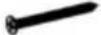 M3.5x35mm M3.5x35mm | M4x18mm | -DL-DR |
19


natural_image
Isometric diagram of two vertical panels mounted on a base with mounting holes and a central rod (no text or symbols)
natural_image
Isometric line drawing of a mechanical support structure with no text or symbols

| R | X1 | P | X1 |
| | ||
| A | X4 | B | X4 | F | X4 | G | X4 | H | X4 | K | X1 |
| ∅6x40mm | ∅15x11 | [8660]M3.5x14mm | M3.5x35mm | M3x16mm | | ||||||
20

21

| P | X1 | N | X2 | J | X1 | F | X4 |
| M4x18mm | | M3x14mm | M3.5x14mm | ||||
22

natural_image
Technical line drawing of a cabinet with open door and internal compartments, showing internal components (no text or symbols)
PRODUKTPARAMETER
C/O YH Consulting Limited Office 147, Centurion Haus, London Road, Staines-upon-Thames, Surrey, TW18 4AX
VEVOR®
TOUGH TOOLS, HALF PRICE
www.vevor.com/support
VEVOR®
TOUGH TOOLS, HALF PRICE
natural_image
Line drawing of a simple desk cabinet with drawers and doors (no text or symbols)
| A | x47+1 | B | x73+1 | C | x29+1 | D | x5 |
| ∅6x40mm | ∅15x11 | ∅8x30 | ∅8x40 | ||||
| E | x26+1 | F | x36+1 | G | x12 | H | x8 |
| ∅6x32mm | [GX66]M3.5x14mm | M3.5x35mm |  M3x16mm M3x16mm | ||||
| I | x1 | J | x1 | K | x2 | L | x2 |
 M3x14mm M3x14mm |  M3x14mm M3x14mm |  |  M3x14mm M3x14mm | ||||
| M | x4 | N | x2 | O | x73 | P | x4 |
 M5x40mm M5x40mm | 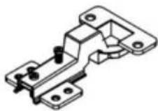 |  ∅20mm ∅20mm | M4x18mm | ||||
| Q | x1 | R | x3 | S | x1 | ||
 M10XJ05HMM M10XJ05HMM | CL CR DL DR | | |||||
| T | x1 | ||||||
 | |||||||
FASE DI MONTAGGIO
1

| I | X1 | F | X4 |
 M3x14mm M3x14mm | [48TY]M3.5x14mm | ||
| X1 | A | X9 | |
| R | X1 | Λ | X9 |
 |  ∅6x40mm ∅6x40mm | ||
2

| C | X3 |
 ∅8x30 ∅8x30 | |
| B | X5 |
 ∅15x11 ∅15x11 | |
∅8×30
| B | X5 |
Φ15×11


11

natural_image
Technical line drawing of a structural frame assembly with mounting holes and internal components (no text or symbols)
12

| F | X2 |
| M3.5x14mm | |
| A | X8 |
| Ø6x40mm | |

15

16

natural_image
Isometric line drawing of a cabinet or enclosure structure with mounting brackets and structural supports (no text or symbols)17

natural_image
Isometric diagram of a rectangular plate with two vertical supports and a central circle labeled '15' (no text or symbols beyond labels)
natural_image
Technical line drawing of two vertical panels mounted on a base with mounting holes and a central rod (no text or symbols)
natural_image
Isometric line drawing of a mechanical support structure with no text or symbols


| R | X1 | P | X1 |
| | ||
| A | X4 | B | X4 | F | X4 | G | X4 | H | X4 | K | X1 |
| ∅6x40mm | Φ15x11 | M3.5x14mm | M3.5x35mm | M3x16mm | | ||||||
18


natural_image
Technical line drawing of a metal frame assembly with mounting holes and a central circular component (no text or symbols)
natural_image
Technical line drawing of a rectangular structural frame with labeled dimensions G and 21 (no text or symbols beyond labels)
| A | X6 | B | X6 | F | X4 | G | X4 | P | X1 | R | X1 |
| ∅6x40mm | ∅15x11 | M3.5x14mm | M3.5x35mm | M4x18mm | -DL-DR |
19


natural_image
Isometric diagram of two vertical panels mounted on a base with mounting holes and a central rod (no text or symbols)
natural_image
Isometric line drawing of a mechanical support structure with no text or symbols


| R | X1 | P | X1 |
| | ||
| A | X4 | B | X4 | F | X4 | G | X4 | H | X4 | K | X1 |
| ∅6x40mm | Φ15x11 |  M3.5x14mm M3.5x14mm | M3.5x35mm | M3x16mm | | ||||||
20


21

| P | X1 | N | X2 | J | X1 | F | X4 |
| M4x18mm | | M3x14mm | [wosc]M3.5x14mm | ||||
22

natural_image
Technical line drawing of a cabinet with open door and internal compartments, showing internal components (no text or symbols)
PARAMETRO PRODOTTO
Importato in AUS: SIHAO PTY LTD. 1 ROKEVA STREETEASTWOOD
Nuovo Galles del Sud 2122 Australia
C/O YH Consulting Limited Ufficio 147, Centurion Casa, London Road, Staines-upon-Thames, Surrey,
Modello TW18 4AX
VEVOR®
TOUGH TOOLS, HALF PRICE
elettronica www.vevor.com/support
VEVOR®
TOUGH TOOLS, HALF PRICE
natural_image
Line drawing of a simple desk cabinet with drawers and doors (no text or symbols)
| A | x47+1 | B | x73+1 | C | x29+1 | D | x5 |
| ∅6x40mm | ∅15x11 | ∅8x30 | ∅8x40 | ||||
| E | x26+1 | F | x36+1 | G | x12 | H | x8 |
| ∅6x32mm | [S55D]M3.5x14mm | M3.5x35mm | M3x16mm | ||||
| I | x1 | J | x1 | K | x2 | L | x2 |
| M3x14mm | M3x14mm | | M3x14mm | ||||
| M | x4 | N | x2 | O | x73 | P | x4 |
| M5x40mm | | ∅20mm | M4x18mm | ||||
| Q | x1 | R | x3 | S | x1 | ||
| M10XJ05HMM | CL CR DL DR | | |||||
| T | x1 | ||||||
| |||||||
PASO DE MONTAJE
1

| I | X1 | F | X4 |
| [0xH6]M3.5x14mm | ||
| X1 | X9 | ||
| R | X1 | Λ | X9 |
| | ||
2


| C | X3 |
| ∅8x30 | |
| B | X5 |
| Φ15x11 | |
∅8×30
| B | X5 |
| |
| 15× 11 |


11

natural_image
Technical line drawing of a structural frame assembly with mounting holes and internal components (no text or symbols)
12

| F | X2 |
| M3.5x14mm | |
| A | X8 |
| Ø6x40mm | |

15
16

natural_image
Isometric line drawing of a cabinet or enclosure structure with mounting brackets and structural supports (no text or symbols)17

natural_image
Isometric diagram of a rectangular plate with two vertical supports and a central circle labeled '15' (no text or symbols beyond labels)
natural_image
Technical line drawing of two vertical panels mounted on a base with mounting holes and a central rod (no text or symbols)
natural_image
Isometric line drawing of a mechanical support structure with no text or symbols


| R | X1 | P | X1 |
| | ||
| A | X4 | B | X4 | F | X4 | G | X4 | H | X4 | K | X1 |
| ∅6x40mm | Φ15x11 | [∅3AW]M3.5x14mm | M3.5x35mm | [∅X5T]M3x16mm | | ||||||
18

natural_image
Technical line drawing of a metal frame assembly with mounting holes and a central circular component (no text or symbols)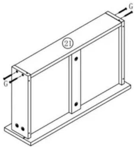
natural_image
Technical line drawing of a rectangular structural frame with labeled dimensions G and 21 (no text or symbols beyond labels)
| A | X6 | B | X6 | F | X4 | G | X4 | P | X1 | R | X1 |
 ∅6x40mm ∅6x40mm | ∅15x11 | [THT2]M3.5x14mm |  M3.5x35mm M3.5x35mm |  M4x18mm M4x18mm | - DLE - DR |
19

natural_image
Isometric diagram of two vertical panels mounted on a base with mounting holes and a central rod (no text or symbols)
natural_image
Isometric line drawing of a mechanical support structure with no text or symbols


| R | X1 | P | X1 |
| | ||
| A | X4 | B | X4 | F | X4 | G | X4 | H | X4 | K | X1 |
| ∅6x40mm | [25X4]∅15x11 | M3.5x14mm | M3.5x35mm | M3x16mm | | ||||||
20


21

| P | X1 | N | X2 | J | X1 | F | X4 |
| M4x18mm | | M3x14mm | M3.5x14mm | ||||
22

natural_image
Technical line drawing of a cabinet with drawers and door, showing internal components and mounting bracket (no text or symbols)
PARÁMETRO DEL PRODUCTO
C/O YH Consulting Limited Oficina 147, Centurion Casa, London Road, Staines-upon-Thames, Surrey, TW18 4AX
VEVOR®
TOUGH TOOLS, HALF PRICE
natural_image
Line drawing of a standard office desk cabinet with drawers and doors (no text or symbols)POTRZEBUJESZ POMOCY? SKONTAKTUJ SIĘ Z NAMI!
| A | x47+1 | B | x73+1 | C | x29+1 | D | x5 |
| ∅6x40mm | ∅15x11 |  ∅8x30 ∅8x30 | ∅8x40 | ||||
| E | x26+1 | F | x36+1 | G | x12 | H | x8 |
| ∅6x32mm | [SZ47]M3.5x14mm |  M3.5x35mm M3.5x35mm | M3x16mm | ||||
| I | x1 | J | x1 | K | x2 | L | x2 |
 M3x14mm M3x14mm | M3x14mm | | 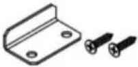 M3x14mm M3x14mm | ||||
| M | x4 | N | x2 | O | x73 | P | x4 |
 M5x40mm M5x40mm | | ∅20mm | 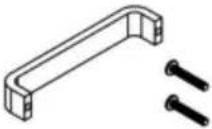 M4x18mm M4x18mm | ||||
| Q | x1 | R | x3 | S | x1 | ||
| M10XJ05HMM | 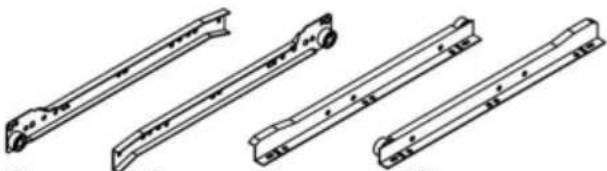 CL CR DL DR CL CR DL DR |  | |||||
| T | x1 | ||||||
 | |||||||
KROK MONTAŻU
1

| I | X1 | F | X4 |
|  M3.5x14mm M3.5x14mm | ||
| X1 | A | X9 | |
| R | X1 | Λ | X9 |
| | ||
2

| C | X3 |
| ∅8x30 | |
| B | X5 |
| Φ15x11 | |
∅8×30
| B | X5 |
| |
| 15× 11 |


11

natural_image
Technical line drawing of a structural frame assembly with mounting holes and internal components (no text or symbols)
12

| F | X2 |
| M3.5x14mm | |
| A | X8 |
| Ø6x40mm | |

15

16

natural_image
Isometric line drawing of a cabinet or enclosure structure with mounting brackets and structural supports (no text or symbols)17

natural_image
Isometric diagram of a rectangular plate with two vertical supports and a central circle labeled '15' (no text or symbols beyond labels)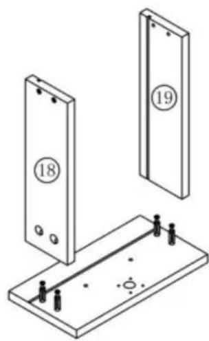
natural_image
Technical line drawing of two vertical panels mounted on a base with mounting holes and a central rod (no text or symbols)
natural_image
Isometric line drawing of a mechanical support structure with no text or symbols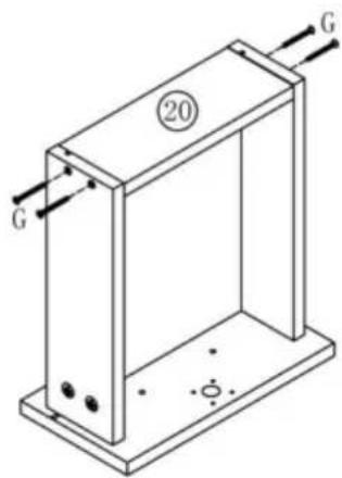
| R | X1 | P | X1 |
 |  | ||
| A | X4 | B | X4 | F | X4 | G | X4 | H | X4 | K | X1 |
| ∅6x40mm | Φ15x11 | M3.5x14mm | M3.5x35mm | M3x16mm | | ||||||
18


natural_image
Technical line drawing of a metal frame assembly with mounting holes and a central circular component (no text or symbols)
natural_image
Technical line drawing of a rectangular structural frame with labeled dimensions G and 21 (no text or symbols beyond labels)
| A | X6 | B | X6 | F | X4 | G | X4 | P | X1 | R | X1 |
| ∅6x40mm | Φ15x11 | M3.5x14mm | M3.5x35mm | M4x18mm | - DL# - DR |
19

natural_image
Isometric diagram of two vertical panels mounted on a base with mounting holes and a central rod (no text or symbols)
natural_image
Isometric line drawing of a mechanical support structure with no text or symbols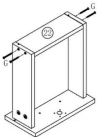


| R | X1 | P | X1 |
 |  | ||
| A | X4 | B | X4 | F | X4 | G | X4 | H | X4 | K | X1 |
| ∅6x40mm | ∅15x11 | M3.5x14mm | M3.5x35mm | M3x16mm | | ||||||
20

21
| P | X1 | N | X2 | J | X1 | F | X4 |
| M4x18mm | | M3x14mm | M3.5x14mm | ||||
22

natural_image
Technical line drawing of a cabinet with drawers and door, showing internal components and mounting bracket (no text or symbols)
PARAMETR PRODUKTU
C/O YH Consulting Limited Biuro 147, Centurion
Dom, London Road, Staines-upon-Thames, Surrey, TW18 4AX
VEVOR®
TOUGH TOOLS, HALF PRICE
natural_image
Line drawing of a simple desk cabinet with drawers and doors (no text or symbols)HULP NODIG? NEEM CONTACT MET ONS OP!

| A | x47+1 | B | x73+1 | C | x29+1 | D | x5 |
| ∅6x40mm | ∅15x11 | ∅8x30 | ∅8x40 | ||||
| E | x26+1 | F | x36+1 | G | x12 | H | x8 |
| ∅6x32mm | M3.5x14mm | M3.5x35mm | M3x16mm | ||||
| I | x1 | J | x1 | K | x2 | L | x2 |
| M3x14mm | M3x14mm | | M3x14mm | ||||
| M | x4 | N | x2 | O | x73 | P | x4 |
| M5x40mm | |  ∅20mm ∅20mm | M4x18mm | ||||
| Q | x1 | R | x3 | S | x1 | ||
| M10XJ05HMM |  CL CR DL DR CL CR DL DR | | |||||
| T | x1 | ||||||
| |||||||
MONTAGESTAP
1

| I | X1 | F | X4 |
| [KXCW]M3.5x14mm | ||
| X1 | X9 | ||
| R | X1 | Λ | X9 |
| | ||
2


| C | X3 |
| ∅8x30 | |
| B | X5 |
| Φ15x11 | |
∅8×30
| B | X5 |
| [×54W] | |
| 15× 11 |


11
natural_image
Technical line drawing of a structural frame assembly with mounting holes and internal components (no text or symbols)
12

| F | X2 |
| M3.5x14mm | |
| A | X8 |
| Ø6x40mm | |

15

16

natural_image
Isometric line drawing of a cabinet or enclosure structure with metal framing and mounting brackets (no text or symbols)17

natural_image
Isometric diagram of a rectangular plate with two vertical supports and a central circle labeled '15' (no text or symbols beyond labels)
natural_image
Technical line drawing of two vertical panels mounted on a base with mounting holes and a central rod (no text or symbols)
natural_image
Isometric line drawing of a mechanical support structure with no text or symbols


| R | X1 | P | X1 |
| | ||
| A | X4 | B | X4 | F | X4 | G | X4 | H | X4 | K | X1 |
| ∅6x40mm | Φ15x11 | M3.5x14mm | M3.5x35mm | M3x16mm | | ||||||
18


natural_image
Technical line drawing of a metal frame assembly with mounting holes and a central circular component (no text or symbols)
natural_image
Technical line drawing of a rectangular structural frame with labeled dimensions G and 21 (no text or symbols beyond labels)
| A | X6 | B | X6 | F | X4 | G | X4 | P | X1 | R | X1 |
| ∅6x40mm | ∅15x11 | [2W0C]M3.5x14mm | M3.5x35mm | M4x18mm | -DL-DR |
19

natural_image
Isometric diagram of a rectangular plate with two vertical supports and a central circle containing the number 17, no text or symbols present.
natural_image
Technical line drawing of a mechanical assembly with two vertical panels and a base plate (no text or symbols)
natural_image
Isometric line drawing of a mechanical support structure with no text or symbols


| R | X1 | P | X1 |
| | ||
| A | X4 | B | X4 | F | X4 | G | X4 | H | X4 | K | X1 |
| ∅6x40mm | ∅15x11 | M3.5x14mm | M3.5x35mm | M3x16mm | | ||||||
20


21

| P | X1 | N | X2 | J | X1 | F | X4 |
| M4x18mm | | M3x14mm | (222V)M3.5x14mm | ||||
22
natural_image
Technical line drawing of a cabinet with drawers and door, showing internal components and mounting bracket (no text or symbols)
©
VEVOR®
TOUGH TOOLS, HALF PRICE
garantiecertificaat www.vevor.com/support
VEVOR®
TOUGH TOOLS, HALF PRICE
natural_image
Line drawing of a simple desk cabinet with drawers and doors (no text or symbols)BEHÖVER HJÄLP? KONTAKTA OSS!
www.vevor.com/support

| A | x47+1 | B | x73+1 | C | x29+1 | D | x5 |
| ∅6x40mm | ∅15x11 | ∅8x30 | ∅8x40 | ||||
| E | x26+1 | F | x36+1 | G | x12 | H | x8 |
| ∅6x32mm | M3.5x14mm | M3.5x35mm | [BXKA]M3x16mm | ||||
| I | x1 | J | x1 | K | x2 | L | x2 |
 M3x14mm M3x14mm | M3x14mm |  |  M3x14mm M3x14mm | ||||
| M | x4 | N | x2 | O | x73 | P | x4 |
 M5x40mm M5x40mm | | ∅20mm | M4x18mm | ||||
| Q | x1 | R | x3 | S | x1 | ||
| M10XJ05HMM | CL CR DL DR | | |||||
| T | x1 | ||||||
 | |||||||
MONTERINGSTEG
1
| I | X1 | F | X4 |
| M3x14mm |  M3.5x14mm M3.5x14mm | ||
| X1 | X9 | ||
| R | X1 | Λ | X9 |
| ∅6x40mm | ||
2


| C | X3 |
| ∅8x30 | |
| B | X5 |
| ∅15x11 | |
∅8×30
| B | X5 |
Φ15×11


11

natural_image
Technical line drawing of a structural frame assembly with mounting holes and internal components (no text or symbols)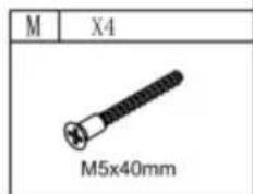
12
| F | X2 |
| M3.5x14mm | |
| A | X8 |
| Ø6x40mm | |

15

16

natural_image
Isometric line drawing of a cabinet or enclosure structure with mounting brackets and structural supports (no text or symbols)17

natural_image
Isometric diagram of a rectangular plate with two vertical supports and a central circle labeled '15' (no text or symbols beyond labels)
natural_image
Technical line drawing of two vertical panels mounted on a base with mounting holes and a central rod (no text or symbols)
natural_image
Isometric line drawing of a mechanical support structure with no text or symbols


| R | X1 | P | X1 |
|  | ||
| A | X4 | B | X4 | F | X4 | G | X4 | H | X4 | K | X1 |
| ∅6x40mm | Φ15x11 | M3.5x14mm | M3.5x35mm | M3x16mm | | ||||||
18


natural_image
Technical line drawing of a metal frame assembly with mounting holes and a central circular component (no text or symbols)
natural_image
Technical line drawing of a rectangular structural frame with labeled dimensions G and 21 (no text or symbols beyond labels)
| A | X6 | B | X6 | F | X4 | G | X4 | P | X1 | R | X1 |
| ∅6x40mm | ∅15x11 | [3XX0]M3.5x14mm | [T4H0]M3.5x35mm | M4x18mm | - DLE - DR |
19

natural_image
Isometric diagram of a rectangular plate with two vertical supports and a central circle containing the number 17, no text or symbols present.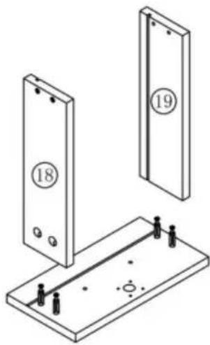
natural_image
Technical line drawing of two vertical panels mounted on a base with mounting holes and a central rod (no text or symbols)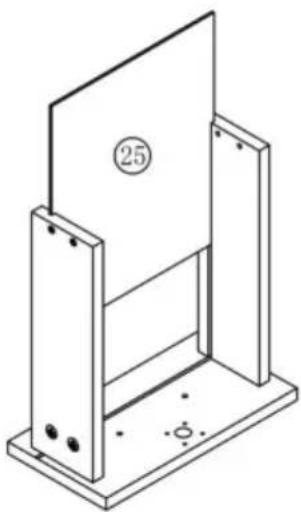
natural_image
Isometric line drawing of a mechanical support structure with no text or symbols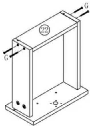


| R | X1 | P | X1 |
| | ||
| A | X4 | B | X4 | F | X4 | G | X4 | H | X4 | K | X1 |
| ∅6x40mm | ∅15x11 | [60x2]M3.5x14mm | [23xT]M3.5x35mm | M3x16mm | | ||||||
20

21

| P | X1 | N | X2 | J | X1 | F | X4 |
| M4x18mm | | M3x14mm |  M3.5x14mm M3.5x14mm | ||||
22

natural_image
Technical line drawing of a cabinet with drawers and door, showing internal components and mounting bracket (no text or symbols)
PRODUKTPARAMETER
| Modell | KLFD-03 |
| 70 kgSäker lastvikt | |
| Färg | Svart |
| Produktstorlek | 1200*480*1100 mm |
Tillverkare: Shanghaimuxinmuyeyouxiangongsi
Adress: Shuangchenglu 803nong11hao1602A-1609shi, baoshanqu, shanghai 200000 CN.
Importerad till AUS: SIHAO PTY LTD. 1 ROKEVA STREETEASTWOOD NSW 2122 Australien
Importerad till USA: Sanven Technology Ltd. Suite 250, 9166 Anaheim Place, Rancho Cucamonga, CA 91730
| EC | REP |
| UK | REP |
E-CrossStu GmbH
Mainzer Landstr.69, 60329 Frankfurt am Main.
YH CONSULTING LIMITED.
C/O YH Consulting Limited Office 147, Centurion
House, London Road, Staines-upon-Thames, Surrey, TW18 4AX
VEVOR®
TOUGH TOOLS, HALF PRICE
www.vevor.com/support