CSF-D24102 - Console table Vevor - Free user manual and instructions
Find the device manual for free CSF-D24102 Vevor in PDF.

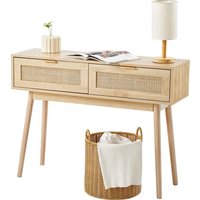
| Product Type | Rattan Console Table |
| Brand | Vevor |
| Model | CSF-D24102 |
| Main Material | Rattan (natural or synthetic rattan) |
| Dimensions (L x W x H) | 1305 x 300 x 815 mm |
| Package Dimensions (L x W x H) | 1405 x 385 x 145 mm |
| Net Weight | Approximately 21.54 kg |
| Gross Weight | Approximately 23.36 kg |
| Maximum Load Capacity | Approximately 50 kg (estimated) |
| Number of Legs | 4 legs |
| Assembly Difficulty Level | Medium |
| Assembly Type | Self-assembly |
| Tools Required for Assembly | Hex key (included), screwdriver (not included) |
| Safety Precautions | Do not exceed weight capacity; use on flat surface; keep children away |
| Intended Use | Indoor use only |
| Maintenance | Wipe with a damp cloth; avoid harsh chemicals |
| Repairability | Spare parts available on request (contact support) |
| Warranty | Electronic warranty via www.vevor.com/support |
| Certifications | Compliant with CE standards (CE representative: E-CrossStu GmbH) |
| Country of Design | China (imported by Sanven Technology Ltd.) |
Frequently Asked Questions - CSF-D24102 Vevor
User questions about CSF-D24102 Vevor
0 question about this device. Answer the ones you know or ask your own.
Ask a new question about this device
Download the instructions for your Console table in PDF format for free! Find your manual CSF-D24102 - Vevor and take your electronic device back in hand. On this page are published all the documents necessary for the use of your device. CSF-D24102 by Vevor.
USER MANUAL CSF-D24102 Vevor
Technical Support and E-Warranty Certificate www.vevor.com/support
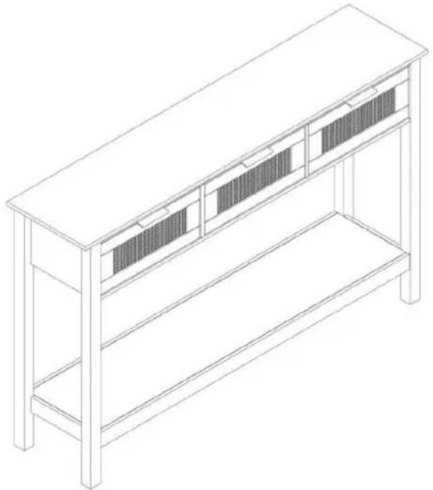
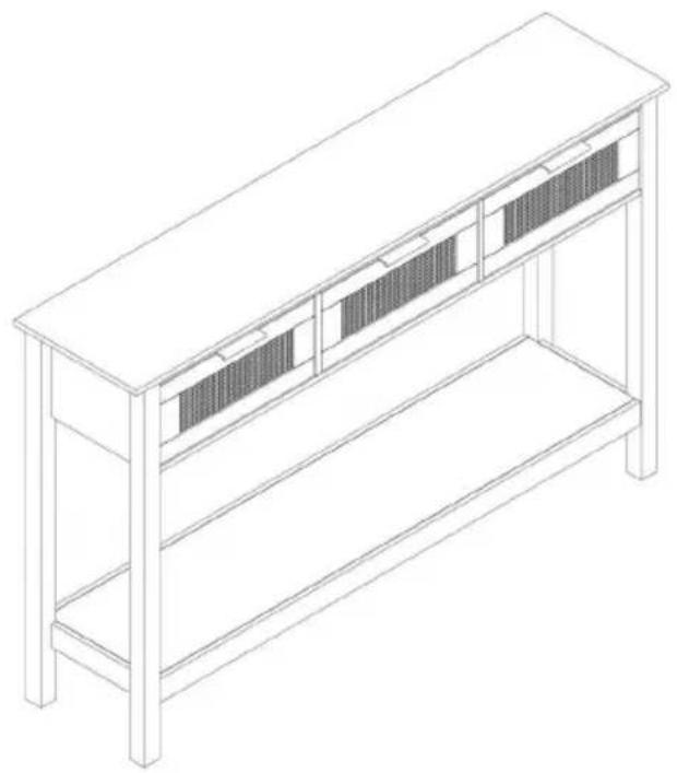
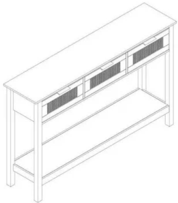
RATTAN CONSOLE TABLE USER MANUAL
MODEL NO.: CSF-D24102
We continue to be committed to provide you tools with competitive price. "Save Half", "Half Price" or any other similar expressions used by us only represent estimate of savings you might benefit from buying certain tools with us compared top brands and does not necessarily mean to cover all categories of tools offered are kindly reminded to verify carefully when you are placing an order with us actually saving half in comparison with the top major brands.
VEVOR®
TOUGH TOOLS, HALF PRICE
Rattan Console Table
MODEL NO.: CSF-D24102
natural_image
Isometric line drawing of a two-level computer or library unit with bookshelves and storage compartments (no text or symbols)NEED HELP? CONTACT US!
Have product questions? Need technical support? Please feel from contact us:
Technical Support and E-Warranty Certificate www.vevor.com/support
This is the original instruction, please read all manual instruction carefully before operating. VEVOR reserves a clear interpretation user manual. The appearance of the product shall be subject to product you received. Please forgive us that we won't inform you there are any technology or software updates on our product.

WARNING:
Please read this manual carefully before using the product. Failure do so may result in serious injury.
ASSEMBLY PRECAUTIONS
- Assemble only according to these instructions. Improper assembly c create hazards.
- Wear ANSI-approved safety goggles and heavy-duty work gloves during assembly.
- Keep the assembly area clean and well-lit.
- Keep bystanders out of the area during assembly.
- Do not assemble when tired or when under the influence of alcohol drugs or medication.
- The product capabilities apply to properly and completely assembled products only.
- Assemble on a flat, level, hard and smooth surface capable of sa supporting the Rattan Console Table.
- For additional information regarding the parts listed in the following pages, please refer to the Assembly Diagram of this manual. Unwrap separate all parts in a clean work area.
SAVE THESE INSTRUCTIONS
USE PRECAUTIONS
TO PREVENT SERIOUS INJURY AND DEATH FROM TIPPING:
- This product is not a toy Do not allow children to play with or r item.
- Do not exceed weight capacities, before moving.
- Use only on a flat, level, hard and smooth surface capable of sa supporting a fully loaded Rattan Console Table.
- Use as intended only.
Inspect before every use; do not use if parts are loose or damaged.
TECHNICAL SPECIFICATIONS
| Model | CSF-D24102 |
| Product Dimensions (LxWxH)(mm) | 1305*300*815 |
| Packing Size(LxWxH)(mm) | 1405*385*145 |
| Net Weight(kg) | About 21.54 |
| Gross Weight(kg) | About 23.36 |
*Products such as specifications, appearance, and design are subject to modification without prior notice.
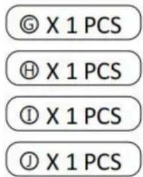
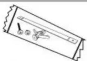
PACKAGE CONTENTS
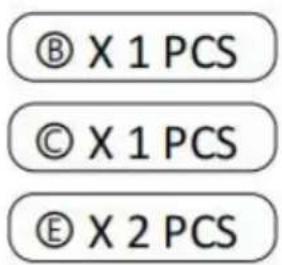
A X1 | B X1 | C X1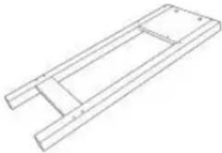 |
D X1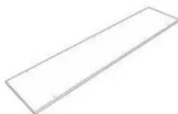 | E X2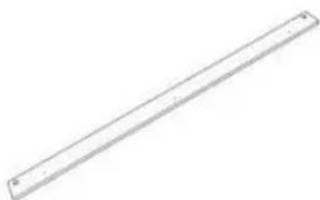 | F X1 |
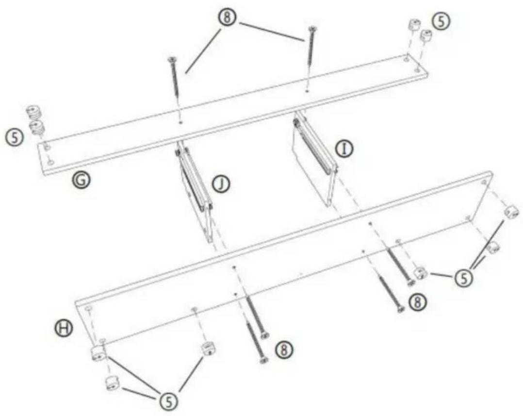
G X1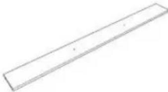 | H X1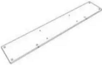 | I X1 |
J X1 | K X3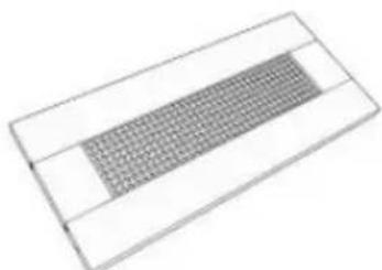 | L X3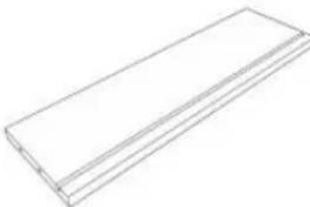 |
M X3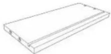 | N X3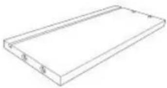 | ◎ X3 |
1 X3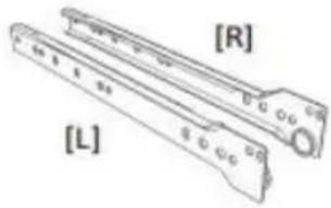 | 2 X3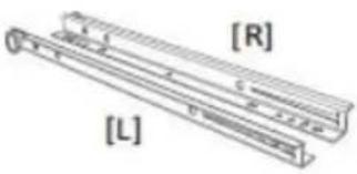 | 3 X3 |
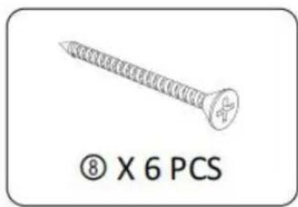
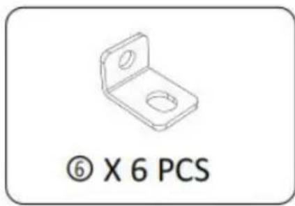
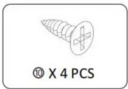
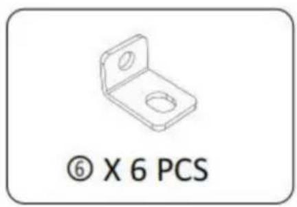
4 X34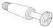 | 5 X34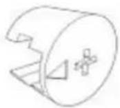 | 6 X6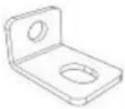 |
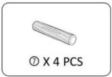
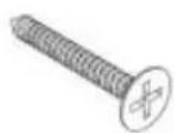
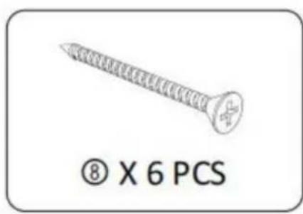
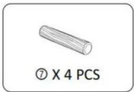
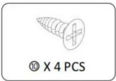
7 X4 | 8 X18 | 9 X3 |
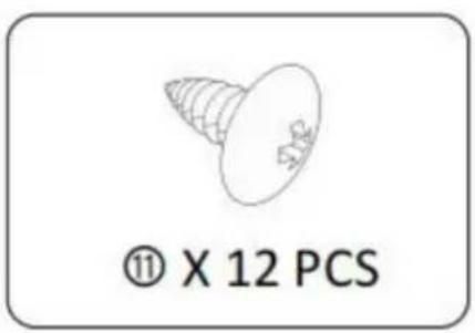
10 X30 | 11 X12 | 12 X1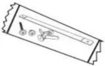 |
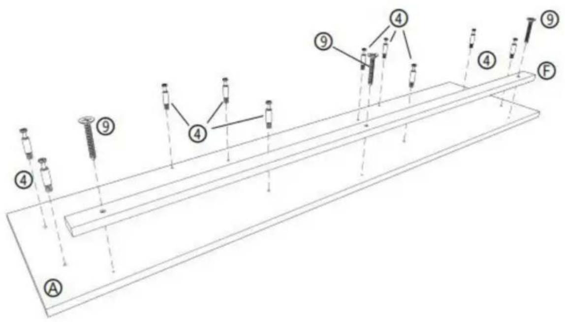
STEP 1 :
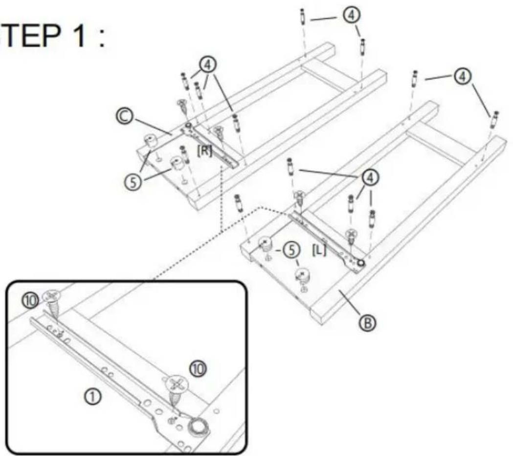
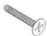
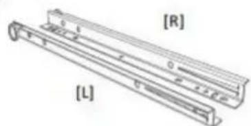
![[R] [L] ① x 1 PCS](/content/2026/04/735012/images/adcd2be9004e87a86932e54a69dc33a0abe55e4471ede0400f2dbc2c3f892673.jpg)
natural_image
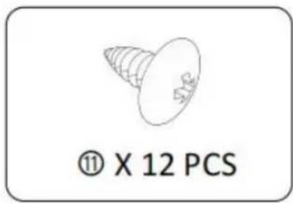
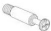
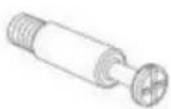
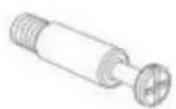
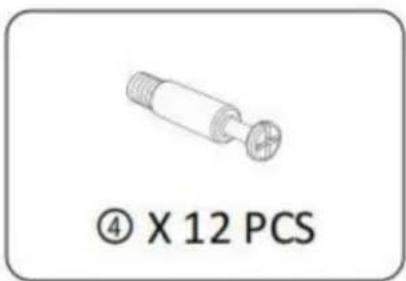
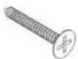
Technical drawing of a mechanical component with threaded end and circular end, labeled (4) X 12 PCS below (no other text or symbols)
STEP 2 :
![P 2 : ① ② ③ ④ ⑤ ⑥ ⑦ ⑧ ⑨ ⑩ 180° [L] [R] [I] [J] [L]](/content/2026/04/735012/images/905d31aca60f1d01df093697686118093c784d65bf22c5696131aec06debc46c.jpg)
![[R] [L]](/content/2026/04/735012/images/4271a60a54ae3357fd11c46e6961495d83ee7197d4e5d874e7de8c550d2d038b.jpg)
① X 2 PCS
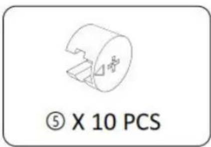
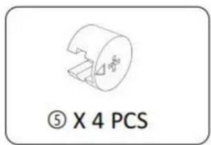
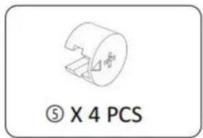
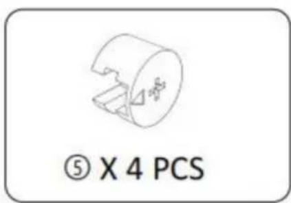
⑤ X 4 PCS
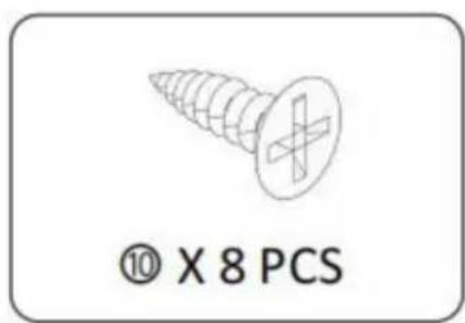
⑩ X 8 PCS
① X 1 PCS
① X 1 PCS
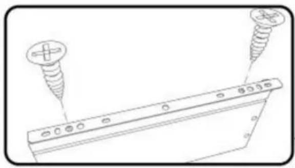
STEP 3 :
STEP 4 :
STEP 5 :

STEP 6 :
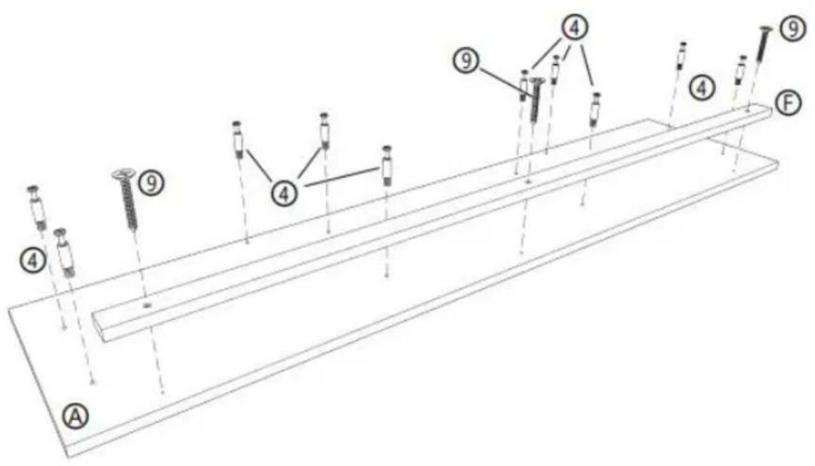
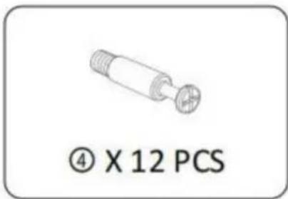
④ X 10 PCS
⑨ X 3 PCS
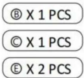
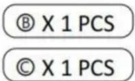
Ⓐ X 1 PCS
⑤ X 1 PCS
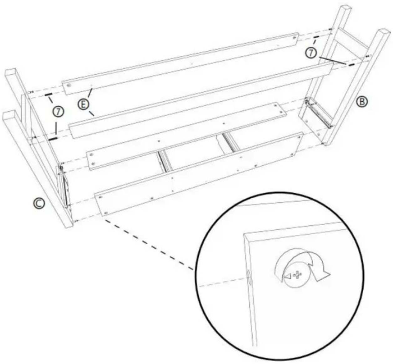
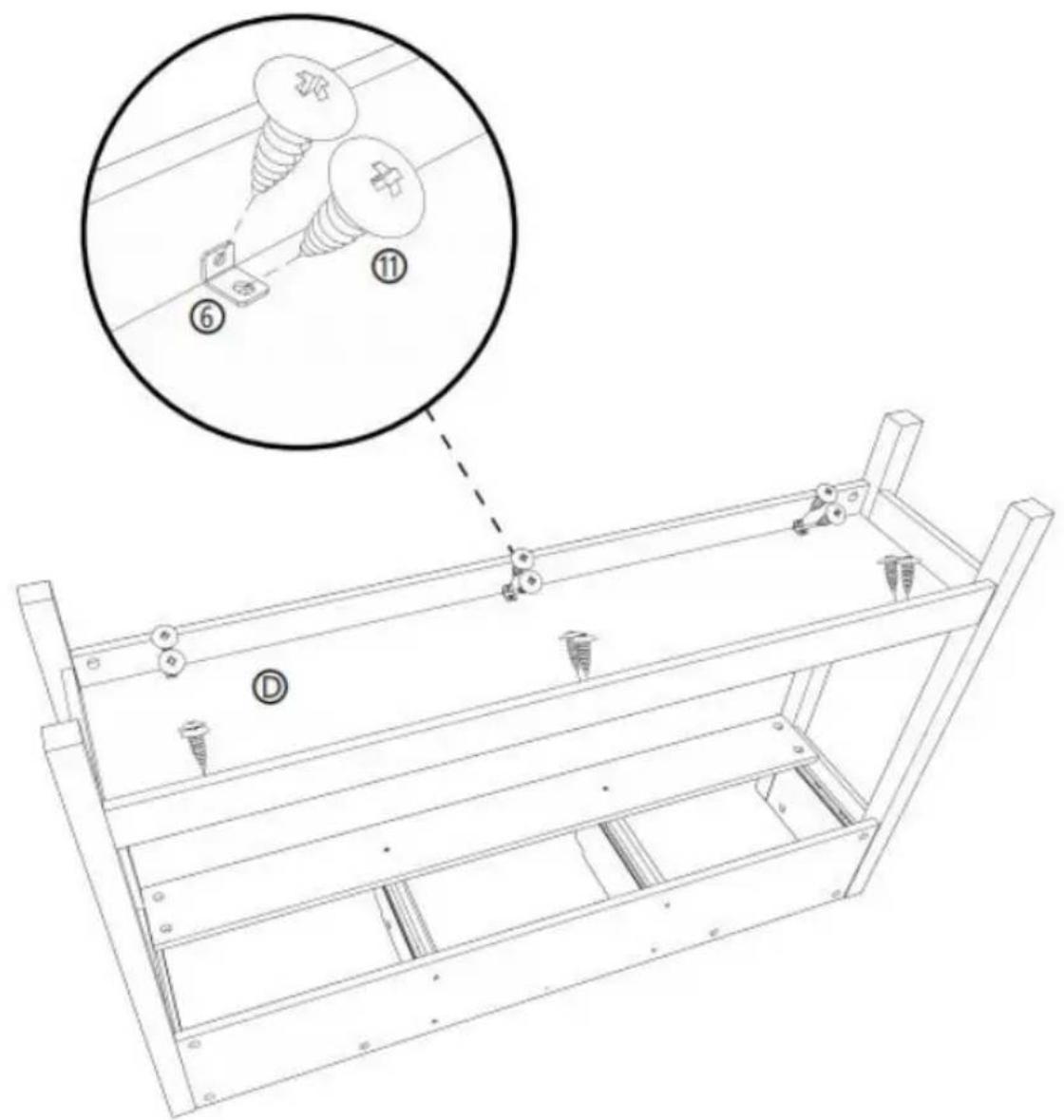
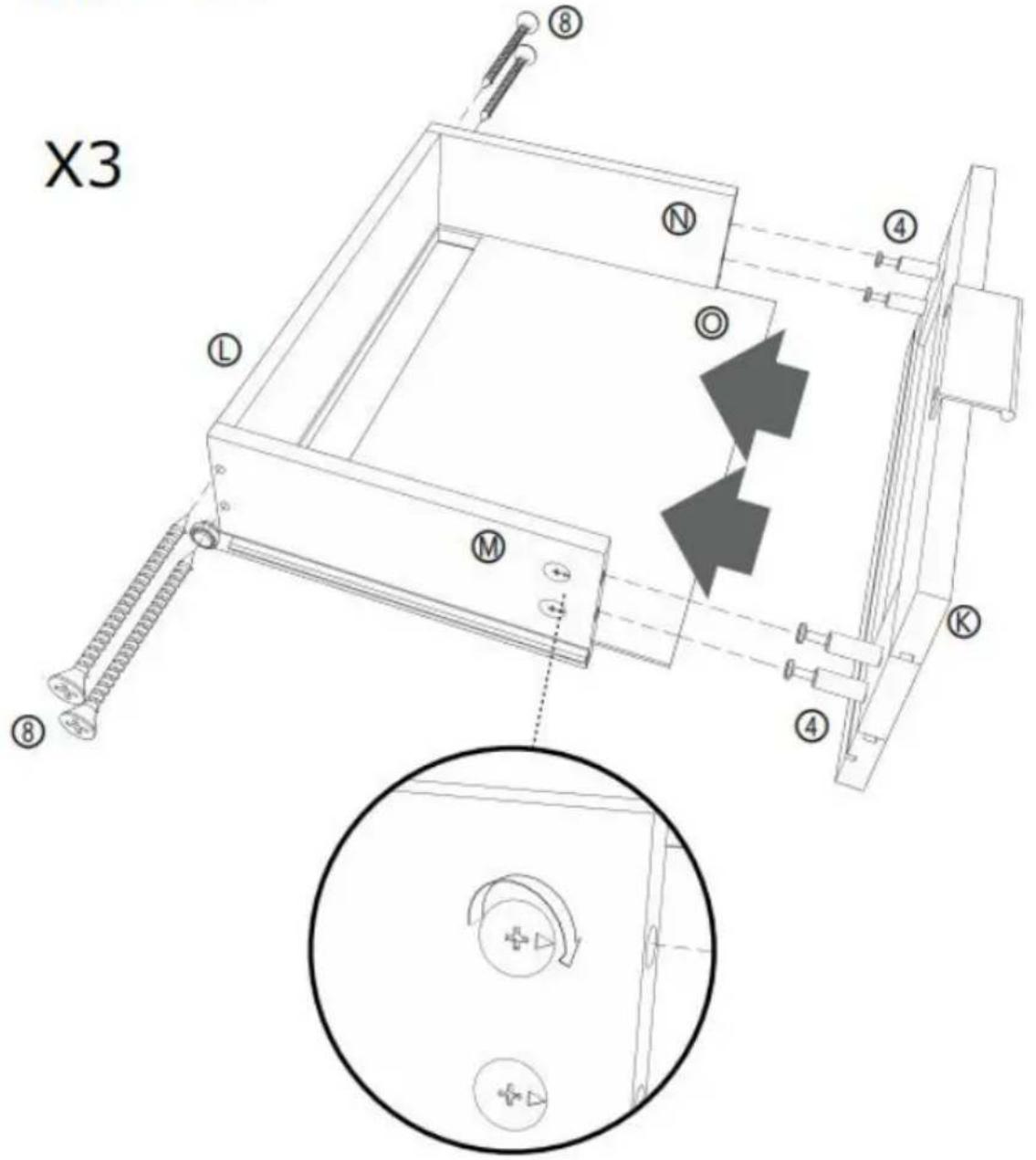
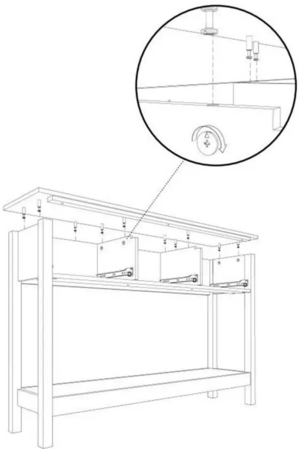
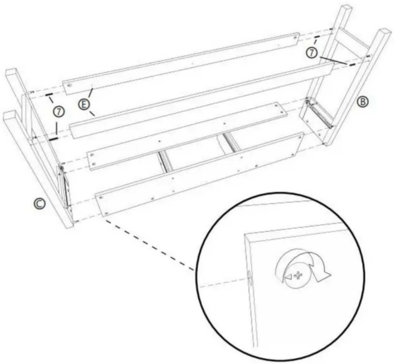
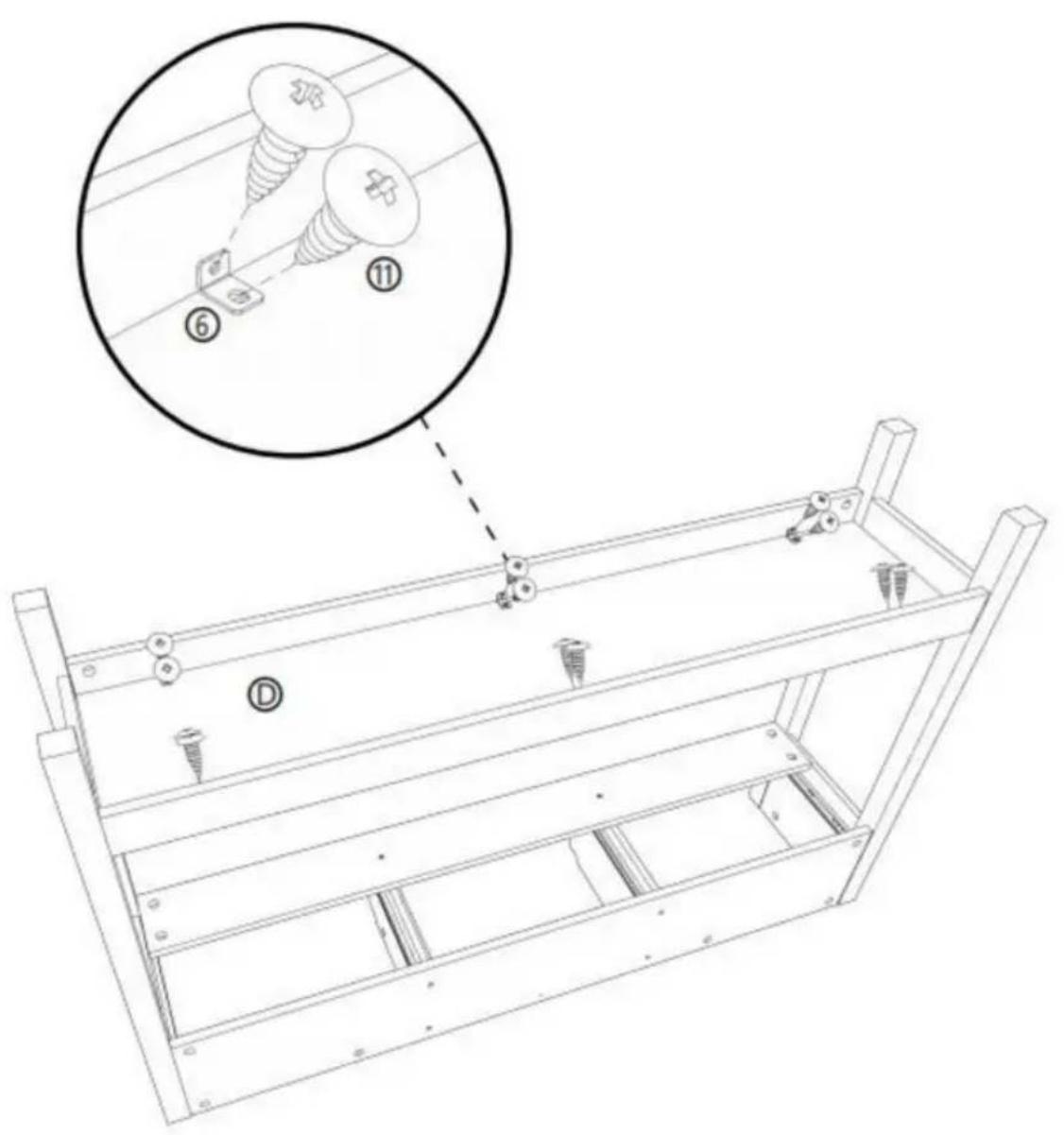
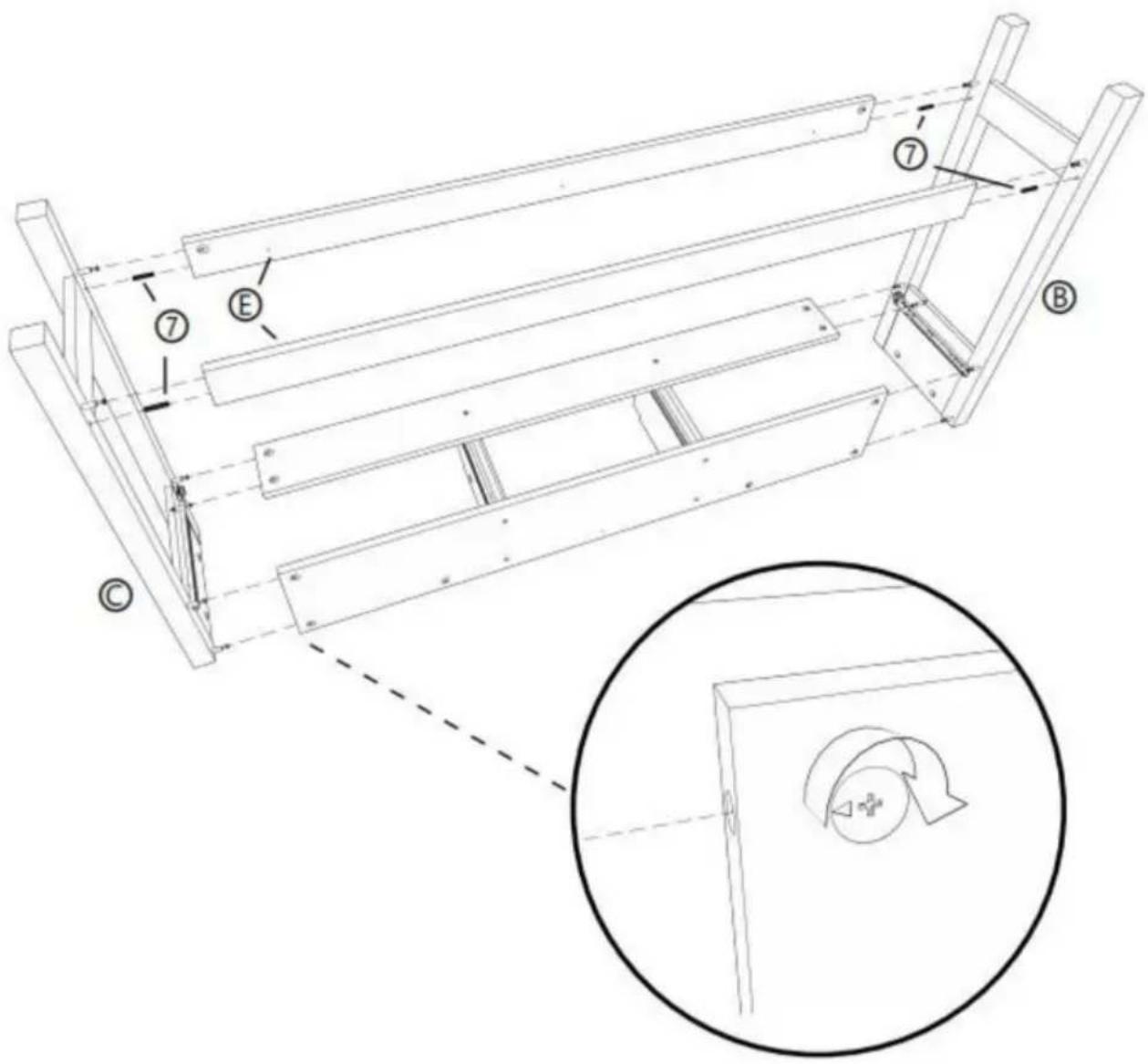
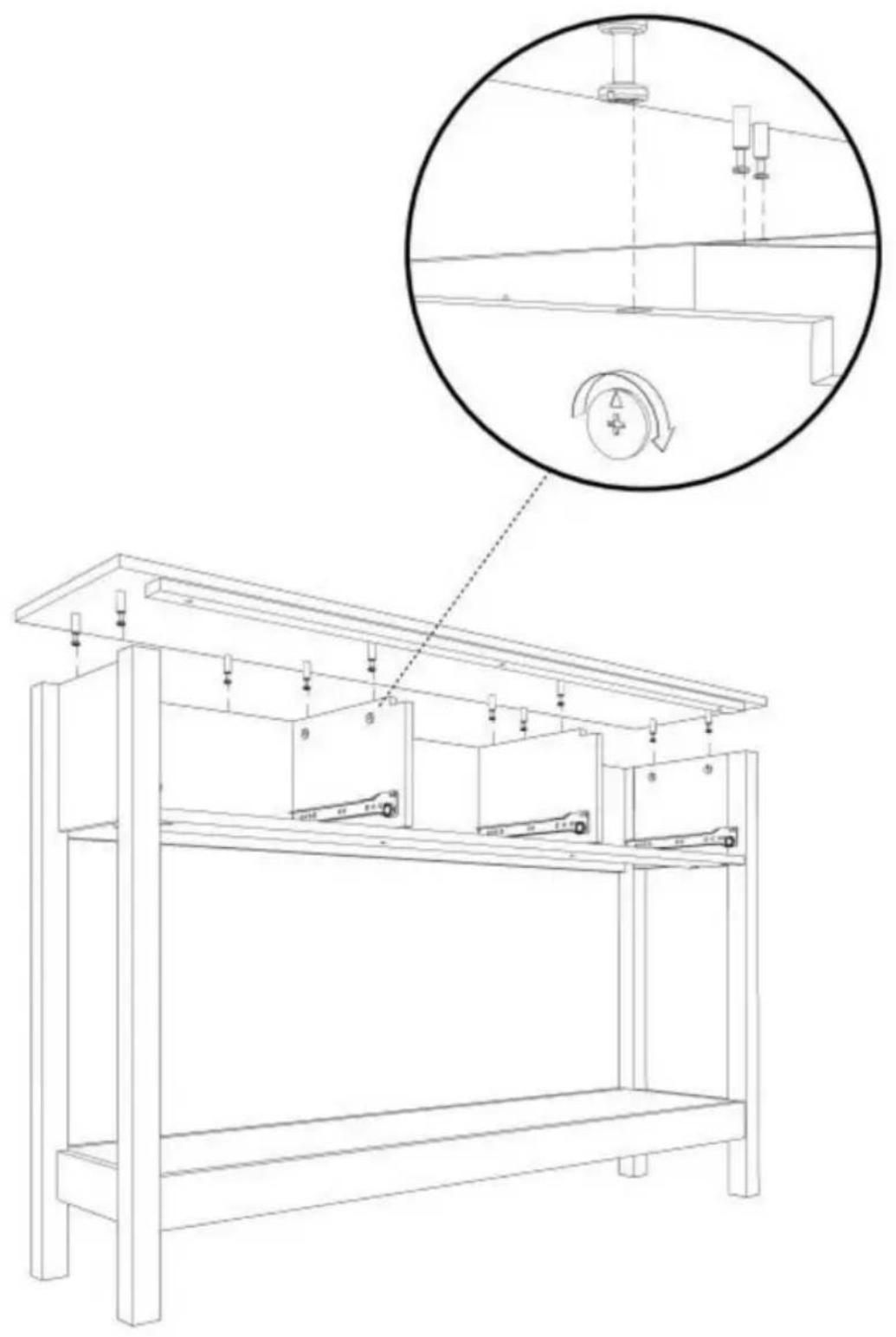
STEP 7 :
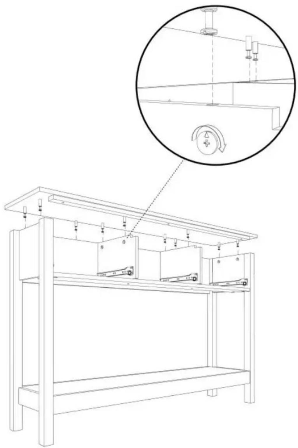
natural_image
Technical line drawing of a mechanical assembly with labeled components and an inset magnified view (no text or symbols)STEP 8 :
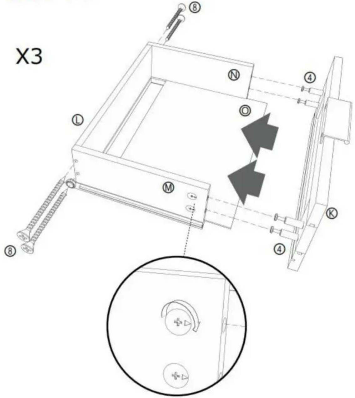
X3
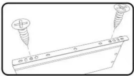
natural_image
Technical line drawing of a mechanical assembly with screw fasteners and a bracket (no text or symbols)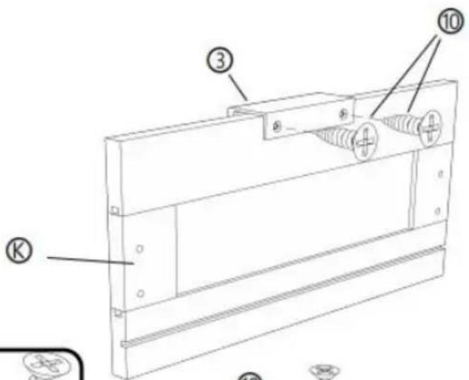
![[R] [M] [L] ① ② ⑩ ⑩ ② ⑨](/content/2026/04/735012/images/9ba91b76ffee31e80c6a52cb4da15b88c79ecefe0bb0a7bb8e45815ba7a97000.jpg)
![[R] [L]](/content/2026/04/735012/images/74434d0274f31fffdc3c704a4a0c8096b4bba2285927c407870a6b4d57412af7.jpg)
② X 3 PCS
③ X 3 PCS

⑩ X 18 PCS
© X 3 PCS
⑧ X 3 PCS
⑨ X 3 PCS
STEP 9 :
⑧ X 12 PCS
④ X 12 PCS
© X 3 PCS
① X 3 PCS
⑧ X 3 PCS
⑨ X 3 PCS
⑨ X 3 PCS
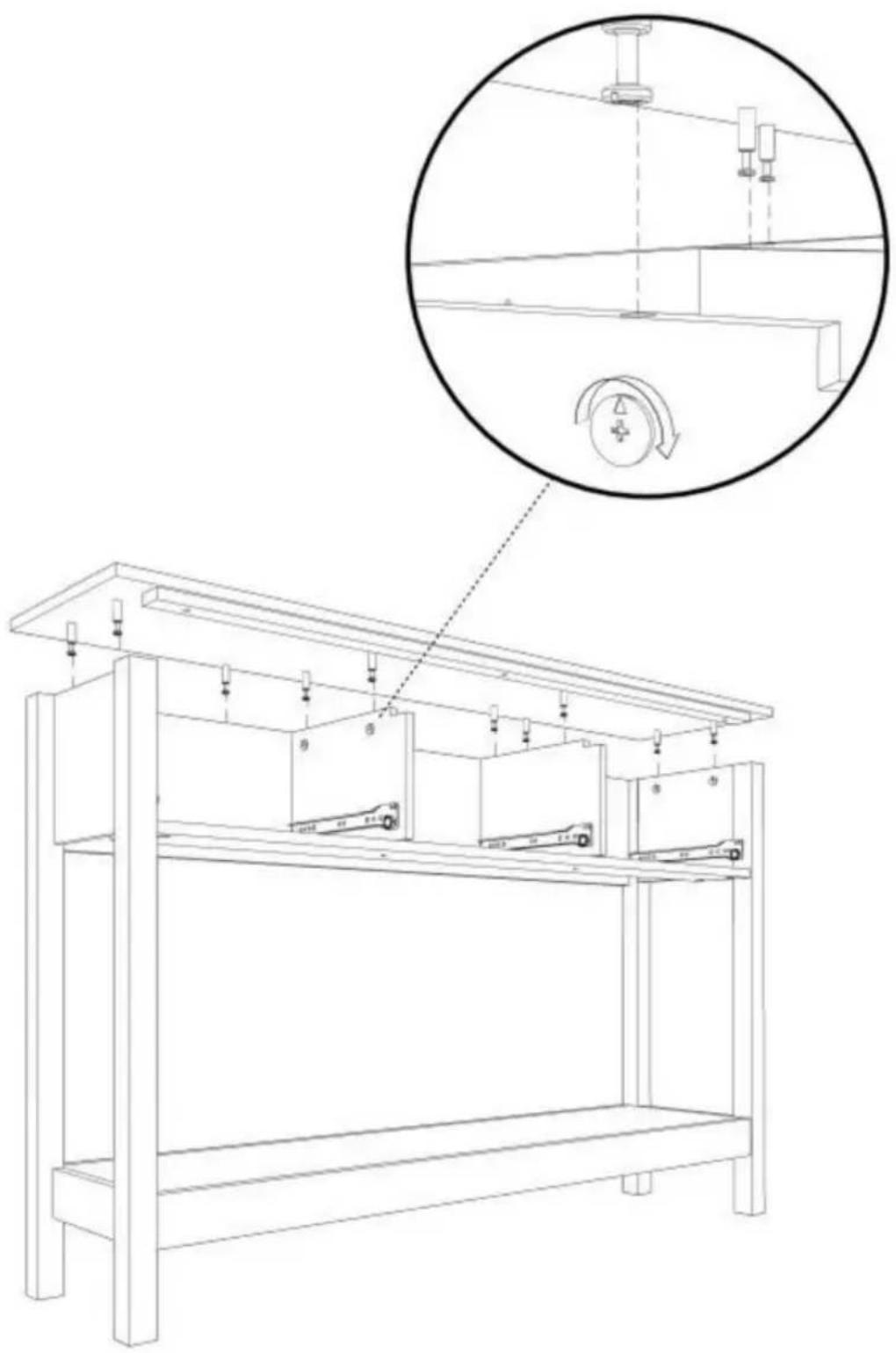
STEP 10 :

natural_image
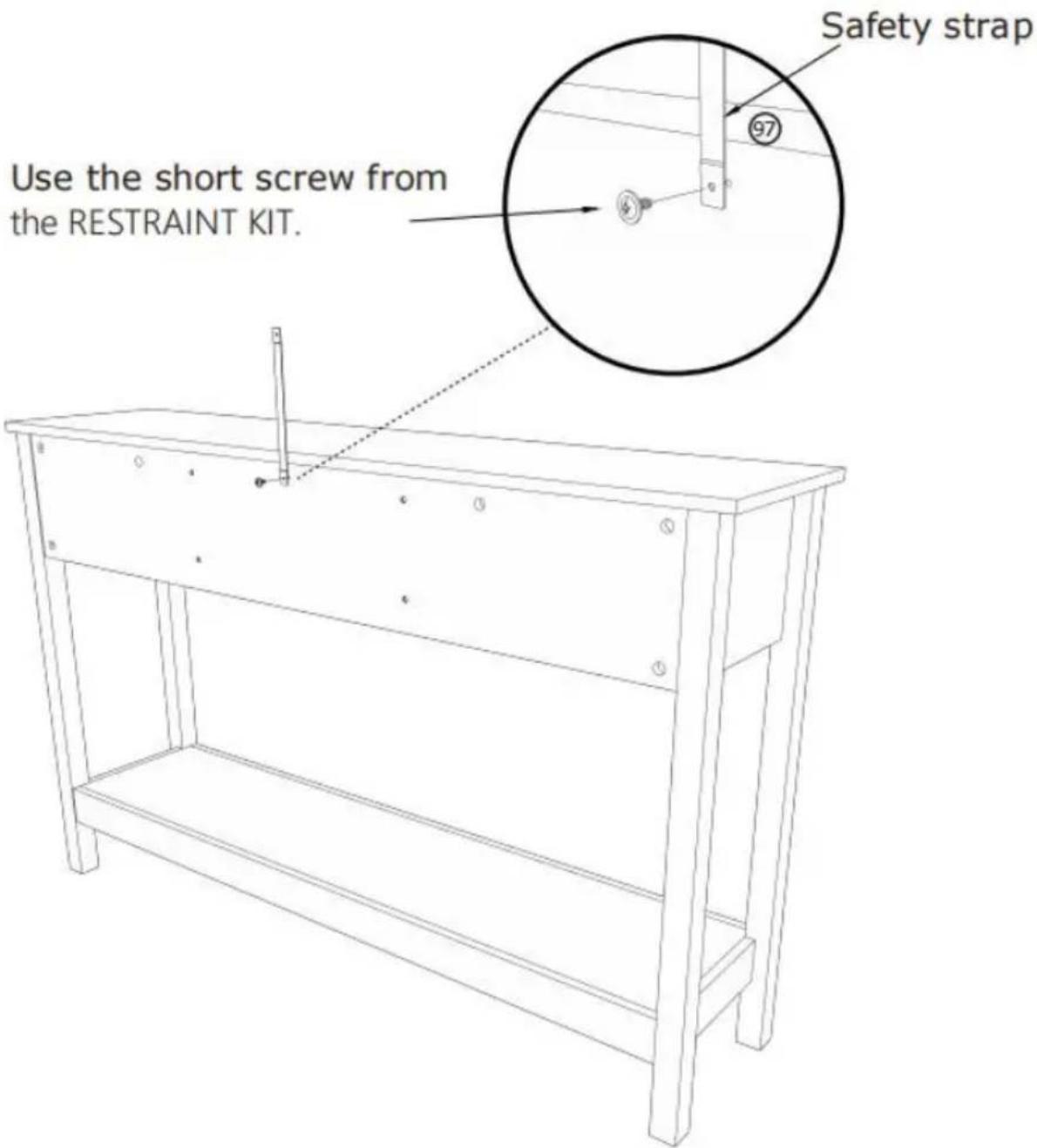
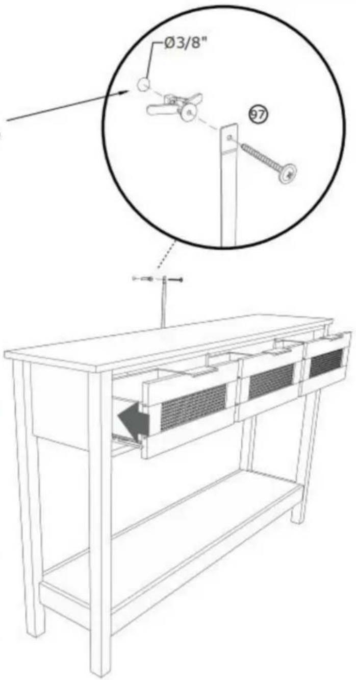
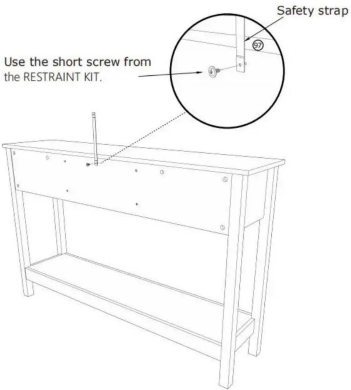
Simple line drawing of a rectangular object with internal components and no visible text or symbols⑨7 X 1 PCS
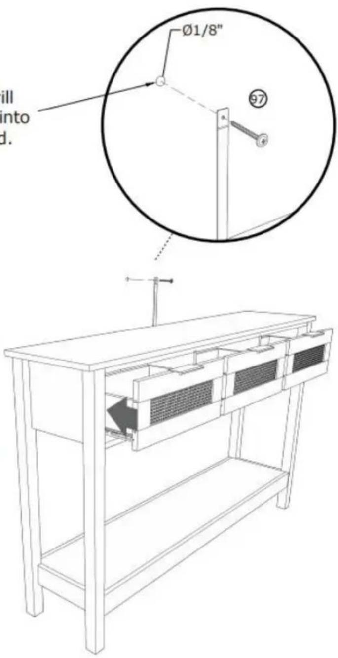
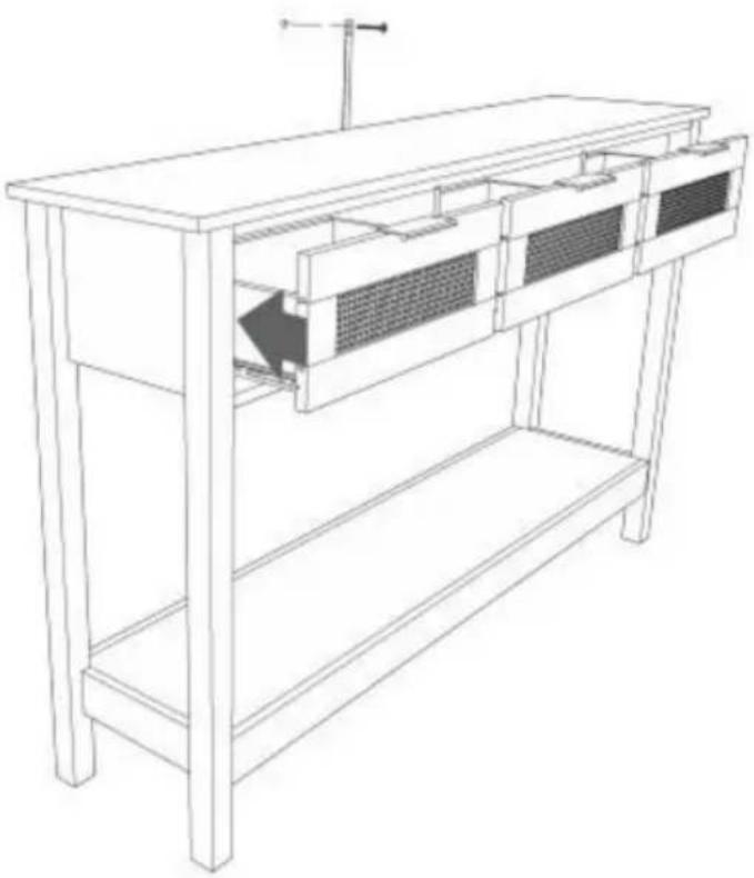
STEP 11 :
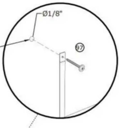
Mark and drill a 1/8" hole into the wall stud.
Carefully stand your unit upright against the wall in its final location.
1st- Locate the center of a stud in your wall near your unit and mark it with a pencil.
2nd- Drill a 1/8" hole on the mark and into the stud in your wall.
3rd- Fasten the unit to the wall. Use the long screw through the other end of the strap and into the 1/8" hole.
natural_image
Simple line drawing of a rectangular object with internal components and a small circular symbol inside (no text or labels)⑨7 X 1 PCS
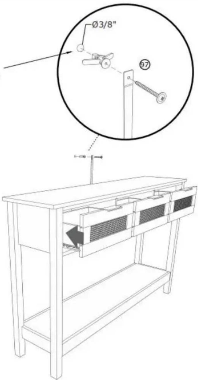
STEP 12 :
Mark and drill a 3/8" hole into the wall stud.
Carefully stand your unit upright against the wall in its final location.
1st- With your pencil, strike a mark through the center of the hole in the SAFETY STRAP.
2nd- Drill a 3/8" hole on the mark.
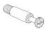
3rd- While you squeeze the wings together, gently tap the WALL ANCHOR from the FURNITURE TIPPING RESTRAINT KIT (97) into the hole until it is even with the surface of the wall.
4th- Turn the long screw through the hole in the SAFETY STRAP and into the WALL ANCHOR.
natural_image
Line drawing of a mechanical component with no visible text or symbols⑨7 X 1 PCS
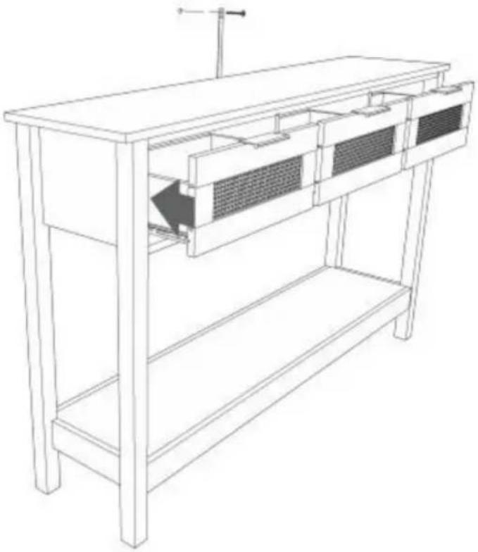
COMPLETION
natural_image
Line drawing of a simple wooden cabinet with three drawers and a shelf (no text or symbols)Manufacturer: Shanghaimuxinmuyeyouxiangongsi
Address: Shuangchenglu 803nong11hao1602A-1609shi, baoshanqu, shanghai 200000 CN.
Imported to AUS: SIHAO PTY LTD. 1 ROKEVA STREETEASTWOOD NSW 2122 Australia
Imported to USA: Sanven Technology Ltd. Suite 250, 9166 Anaheim Place, Rancho Cucamonga, CA 91730
| EC | REP |
E-CrossStu GmbH
Mainzer Landstr.69, 60329 Frankfurt am Main
| UK | REP |
YH CONSULTING LIMITED.
C/O YH Consulting Limited Office 147, Centurion House, London Road, Staines-upon-Thames, Surrey TW18 4AX
VEVOR®
TOUGH TOOLS, HALF PRICE
Technical Support and E-Warranty Certificate
www.vevor.com/support
VEVOR®
TOUGH TOOLS, HALF PRICE
natural_image
Line drawing of a simple wooden bookshelf with drawers and storage compartments (no text or symbols)BESOIN D'AIDE? CONTACTEZ-NOUS!


STEP 2 :
![P 2 : ① ② ③ ④ ⑤ ⑥ [1] [2] [3] [4] [5] [6] [7] [8] [9] [10] 180° ① ② ③ ④ ⑤ ⑥ [1] [2] [3] [4] [5] [6] [7] [8] [9] [10]](/content/2026/04/735012/images/8ff4cb3609ffb0f47348c38adc8a189eac21cc4e3fd4bd54dbe2df1005b3745e.jpg)
![[R] [L] ① X 2 PCS](/content/2026/04/735012/images/1965ab9a974934eedf04a6f3302c6368c796a68a0ed34d54d87a648503caa430.jpg)


STEP 3 :


STEP 4 :


STEP 5 :


STEP 6 :


④ X 10 PCS

⑨ X 3 PCS
Ⓐ X 1 PCS
⑤ X 1 PCS
STEP 7 :
natural_image
Technical line drawing of a mechanical assembly with labeled components and an inset showing a circular component (no text or symbols present)STEP 8 :
X3

natural_image
Technical line drawing of a mechanical assembly with two screws and a base plate (no text or symbols)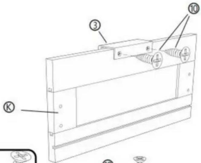
![[R] [M] [L] ① ② ⑩ ⑩ ② ④](/content/2026/04/735012/images/de46b741f806d3d9f2f28340f730b1b4a0bce2ed9d465d43fe28862e88522c23.jpg)

natural_image
Technical line drawing of a mechanical component with labeled parts [R] and [L], showing no text or symbols beyond labels.② X 3 PCS
③ X 3 PCS

⑩ X 18 PCS
© X 3 PCS
⑧ X 3 PCS
⑨ X 3 PCS
STEP 9 :


⑧ X 12 PCS
④ X 12 PCS
© X 3 PCS
⑤ X 3 PCS
⑧ X 3 PCS
⑨ X 3 PCS
⑨ X 3 PCS
STEP 10 :


natural_image
Simple line drawing of a rectangular object with internal components and a gear-like element (no text or symbols)⑨7 X 1 PCS
STEP 11 :
Mark and drill a 1/8" hole into the wall stud.

Carefully stand your unit upright against the wall in its final location.
1st- Locate the center of a stud in your wall near your unit and mark it with a pencil.
2nd- Drill a 1/8" hole on the mark and into the stud in your wall.
3rd- Fasten the unit to the wall. Use the long screw through the other end of the strap and into the 1/8" hole.
natural_image
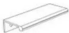
Line drawing of a wooden bench with internal grating and a hanging rod (no text or symbols)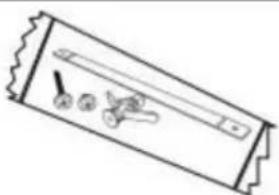
natural_image
Simple line drawing of a rectangular object with internal components and no visible text or symbols⑨7 X 1 PCS
STEP 12 :
Mark and drill a 3/8" hole into the wall stud.
Carefully stand your unit upright against the wall in its final location.
1st- With your pencil, strike a mark through the center of the hole in the SAFETY STRAP.
2nd- Drill a 3/8" hole on the mark.
3rd- While you squeeze the wings together, gently tap the WALL ANCHOR from the FURNITURE TIPPING RESTRAINT KIT (97) into the hole until it is even with the surface of the wall.
4th- Turn the long screw through the hole in the SAFETY STRAP and into the WALL ANCHOR.

natural_image
Simple line drawing of a rectangular object with internal components and no visible text or symbols⑨7 X 1 PCS
ACHÈVEMENT

natural_image
Line drawing of a simple wooden bookshelf with two shelves and a shelf, no text or symbols presentFabricant: Shanghaimuxinmuyeyouxiangongsi
Adresse : Shuangchenglu 803nong11hao1602A-1609shi, baoshanqu, Shanghai 200000 CN.
Importé en Australie : SIHAO PTY LTD. 1 ROKEVA STREETEASTWOOD NSW 2122 Australie
A/S YH Consulting Limited Bureau 147, Centurion
Maison, London Road, Staines-upon-Thames, Surrey, TW18 4AX
VEVOR®
TOUGH TOOLS, HALF PRICE
natural_image
Line drawing of a simple wooden bookshelf with drawers and storage compartments (no text or symbols)
STEP 2 :
![P 2 : ① ② ③ ④ ⑤ ⑥ [1] [2] [3] [4] [5] [6] [7] [8] [9] [10] 180° ① ② ③ ④ ⑤ ⑥ [1] [2] [3] [4] [5] [6] [7] [8] [9] [10]](/content/2026/04/735012/images/82ee4ef1fe9f124c9aea7b1c37f0ba7fdf592f7ee2bd539ecb4c455e497960bf.jpg)
![[R] [L] ① X 2 PCS](/content/2026/04/735012/images/cd6c8f320364646181c9a82e4fa0a2d2f3459024b3a9eabb5c9c635523b17e73.jpg)


STEP 3 :


STEP 4 :

STEP 5 :


STEP 6 :


④ X 10 PCS
⑨ X 3 PCS
Ⓐ X 1 PCS
⑤ X 1 PCS
STEP 7 :

natural_image
Technical line drawing of a mechanical assembly with a magnified inset showing internal components (no text or symbols)STEP 8 :
X3

natural_image
Technical line drawing of a mechanical assembly with two screws and a base plate (no text or symbols)
![[R] [M] [L] ① ② ⑩ ⑩ ② ④](/content/2026/04/735012/images/c5bd4961ff84f065b25b9455c6bdfce1c4ca028f5bd664e3dc37d50c1c2eafff.jpg)

natural_image
Technical line drawing of a mechanical component with labeled parts [R] and [L], showing no text or symbols beyond labels.② X 3 PCS

③ X 3 PCS

⑩ X 18 PCS
© X 3 PCS
⑧ X 3 PCS
⑨ X 3 PCS
STEP 9 :


⑧ X 12 PCS

④ X 12 PCS
© X 3 PCS
① X 3 PCS
⑧ X 3 PCS
⑨ X 3 PCS
⑨ X 3 PCS
STEP 10 :


natural_image
Simple line drawing of a rectangular object with internal components and a gear-like element (no text or symbols)⑨7 X 1 PCS
STEP 11 :
Mark and drill a 1/8" hole into the wall stud.

Carefully stand your unit upright against the wall in its final location.
1st- Locate the center of a stud in your wall near your unit and mark it with a pencil.
2nd- Drill a 1/8" hole on the mark and into the stud in your wall.
3rd- Fasten the unit to the wall. Use the long screw through the other end of the strap and into the 1/8" hole.

natural_image
Line drawing of a wooden bench with internal grating and a hanging rod (no text or symbols)
natural_image
Simple line drawing of a rectangular object with internal components and no visible text or symbols⑨7 X 1 PCS
STEP 12 :
Mark and drill a 3/8" hole into the wall stud.
Carefully stand your unit upright against the wall in its final location.
1st- With your pencil, strike a mark through the center of the hole in the SAFETY STRAP.
2nd- Drill a 3/8" hole on the mark.
3rd- While you squeeze the wings together, gently tap the WALL ANCHOR from the FURNITURE TIPPING RESTRAINT KIT (97) into the hole until it is even with the surface of the wall.
4th- Turn the long screw through the hole in the SAFETY STRAP and into the WALL ANCHOR.

natural_image
Simple line drawing of a rectangular object with internal components and no visible text or symbols⑨7 X 1 PCS

FERTIGSTELLUNG

natural_image
Line drawing of a simple wooden table with bookshelves and drawers (no text or symbols)Hersteller: Shanghaimuxinmuyeyouxiangongsi
Adresse: Shuangchenglu 803nong11hao1602A-1609shi, baoshanqu, Shanghai 200000 CN.
Nach AUS importiert: SIHAO PTY LTD. 1 ROKEVA STREETEASTWOOD NSW 2122 Australien
Importiert in die USA: Sanven Technology Ltd. Suite 250, 9166 Anaheim Ort, Rancho Cucamonga, CA 91730
C/O YH Consulting Limited Office 147, Centurion
Haus, London Road, Staines-upon-Thames, Surrey, TW18 4AX
VEVOR®
TOUGH TOOLS, HALF PRICE
www.vevor.com/support
VEVOR®
TOUGH TOOLS, HALF PRICE
natural_image
Line drawing of a simple wooden bookshelf with drawers and storage compartments (no text or symbols)


STEP 2 :
![P 2 : ① ② ③ ④ ⑤ ⑥ [1] [2] [3] [4] [5] [6] [7] [8] [9] [10] 180° ① ② ③ ④ ⑤ ⑥ [1] [2] [3] [4] [5] [6] [7] [8] [9] [10]](/content/2026/04/735012/images/1776c5df5bae411c6292db2871b8caab9bf2d298ed20db3a8feb8c6ecbc33053.jpg)
![[R] [L] ① X 2 PCS](/content/2026/04/735012/images/2410a7240c78629fc86bf57678cdae218f170367d4f9175d05dc1a6d10087464.jpg)


STEP 3 :


STEP 4 :


STEP 5 :


STEP 6 :

④ X 10 PCS

⑨ X 3 PCS
Ⓐ X 1 PCS
⑤ X 1 PCS
STEP 7 :

natural_image
Technical line drawing of a mechanical assembly with a magnified inset showing internal components (no text or symbols)STEP 8 :
X3

natural_image
Technical line drawing of a mechanical assembly with two screws and a base plate (no text or symbols)
![[R] [M] [L] ① ② ⑩ ⑩ ② ④](/content/2026/04/735012/images/3a782a8e67ea896eaf41d804d376a18a9c8272452c3ba22603ab435d06fae018.jpg)

natural_image
Technical line drawing of a mechanical component with labeled parts [R] and [L], showing no text or symbols beyond labels.② X 3 PCS

③ X 3 PCS
⑩ X 18 PCS
© X 3 PCS
⑧ X 3 PCS
⑨ X 3 PCS
STEP 9 :


⑧ X 12 PCS

④ X 12 PCS
© X 3 PCS
⑤ X 3 PCS
⑧ X 3 PCS
⑨ X 3 PCS
⑨ X 3 PCS
STEP 10 :


natural_image
Simple line drawing of a rectangular object with internal components and a gear-like element (no text or symbols)⑨7 X 1 PCS
STEP 11 :
Mark and drill a 1/8" hole into the wall stud.
Carefully stand your unit upright against the wall in its final location.
1st- Locate the center of a stud in your wall near your unit and mark it with a pencil.
2nd- Drill a 1/8" hole on the mark and into the stud in your wall.
3rd- Fasten the unit to the wall. Use the long screw through the other end of the strap and into the 1/8" hole.

natural_image
Line drawing of a wooden bench with internal grating and a hanging rod (no text or symbols)
natural_image
Simple line drawing of a rectangular object with internal components and no visible text or symbols⑨7 X 1 PCS
STEP 12 :
Mark and drill a 3/8" hole into the wall stud.
Carefully stand your unit upright against the wall in its final location.
1st- With your pencil, strike a mark through the center of the hole in the SAFETY STRAP.
2nd- Drill a 3/8" hole on the mark.
3rd- While you squeeze the wings together, gently tap the WALL ANCHOR from the FURNITURE TIPPING RESTRAINT KIT (97) into the hole until it is even with the surface of the wall.
4th- Turn the long screw through the hole in the SAFETY STRAP and into the WALL ANCHOR.
natural_image
Simple line drawing of a rectangular object with internal components and no visible text or symbols⑨7 X 1 PCS

COMPLETAMENTO

natural_image
Line drawing of a simple wooden table with bookshelves and drawers (no text or symbols)Importato in AUS: SIHAO PTY LTD. 1 ROKEVA STREETEASTWOOD
Nuovo Galles del Sud 2122 Australia
C/O YH Consulting Limited Ufficio 147, Centurion
Casa, London Road, Staines-upon-Thames, Surrey, TW184AX
VEVOR®
TOUGH TOOLS, HALF PRICE
natural_image
Line drawing of a simple wooden bookshelf with drawers and storage compartments (no text or symbols)


STEP 2 :
![P 2 : ① ② ③ ④ ⑤ ⑥ [1] [2] [3] [4] [5] [6] [7] [8] [9] [10] 180° ① ② ③ ④ ⑤ ⑥ [1] [2] [3] [4] [5] [6] [7] [8] [9] [10]](/content/2026/04/735012/images/7d46afad7ef1320d0a11167f3e2552a4f74839139b8b65e221dc3e54106bb2b3.jpg)
![[R] [L] ① X 2 PCS](/content/2026/04/735012/images/688d640fa9e1955ddf105a4894034a36953828a047d666daf8e748f4c79c1b7a.jpg)


STEP 3 :


STEP 4 :


STEP 5 :


STEP 6 :

④ X 10 PCS

⑨ X 3 PCS
Ⓐ X 1 PCS
⑤ X 1 PCS
STEP 7 :

natural_image
Technical line drawing of a mechanical assembly with labeled components and an inset magnified view (no text or symbols)STEP 8 :
X3

natural_image
Technical line drawing of a mechanical assembly with two screws and a base plate (no text or symbols)
![[R] [M] [L] ① ② ⑩ ⑩ ② ④](/content/2026/04/735012/images/308c6a5f8ce5cdd1b48c306ed62e067d14968345fb4541f1f6aa55f450992f48.jpg)

natural_image
Technical line drawing of a mechanical component with labeled parts [R] and [L], showing no text or symbols beyond labels.② X 3 PCS

③ X 3 PCS

⑩ X 18 PCS
© X 3 PCS
⑧ X 3 PCS
⑨ X 3 PCS
STEP 9 :

⑧ X 12 PCS
④ X 12 PCS
© X 3 PCS
① X 3 PCS
⑧ X 3 PCS
⑨ X 3 PCS
⑨ X 3 PCS
STEP 10 :


natural_image
Simple line drawing of a rectangular object with internal components and a gear-like element (no text or symbols)⑨7 X 1 PCS
STEP 11 :
Mark and drill a 1/8" hole into the wall stud.

Carefully stand your unit upright against the wall in its final location.
1st- Locate the center of a stud in your wall near your unit and mark it with a pencil.
2nd- Drill a 1/8" hole on the mark and into the stud in your wall.
3rd- Fasten the unit to the wall. Use the long screw through the other end of the strap and into the 1/8" hole.

natural_image
Line drawing of a wooden bench with internal grating and a hanging rod (no text or symbols)
natural_image
Simple line drawing of a rectangular object with internal components and no visible text or symbols⑨7 X 1 PCS
STEP 12 :
Mark and drill a 3/8" hole into the wall stud.
Carefully stand your unit upright against the wall in its final location.
1st- With your pencil, strike a mark through the center of the hole in the SAFETY STRAP.
2nd- Drill a 3/8" hole on the mark.
3rd- While you squeeze the wings together, gently tap the WALL ANCHOR from the FURNITURE TIPPING RESTRAINT KIT (97) into the hole until it is even with the surface of the wall.
4th- Turn the long screw through the hole in the SAFETY STRAP and into the WALL ANCHOR.

natural_image
Simple line drawing of a rectangular object with internal components and no visible text or symbols⑨7 X 1 PCS

TERMINACIÓN

natural_image
Line drawing of a simple wooden table with bookshelves and drawers (no text or symbols)Fabricante: Shanghaimuxinmuyeyouxiangongsi
Dirección: Shuangchenglu 803nong11hao1602A-1609shi, baoshanqu, shanghai 200000 CN.
Importado a Australia: SIHAO PTY LTD. 1 ROKEVA STREETEASTWOOD
C/O YH Consulting Limited Oficina 147, Centurion Casa, London Road, Staines-upon-Thames, Surrey, TW18 4AX
VEVOR®
TOUGH TOOLS, HALF PRICE
natural_image
Line drawing of a simple wooden bookshelf with drawers and storage compartments (no text or symbols)POTRZEBUJESZ POMOCY? SKONTAKTUJ SIĘ Z NAMI!


STEP 2 :
![P 2 : ① ② ③ ④ ⑤ ⑥ [1] [2] [3] [4] [5] [6] [7] [8] [9] [10] 180° ① ② ③ ④ ⑤ ⑥ [1] [2] [3] [4] [5] [6] [7] [8] [9] [10]](/content/2026/04/735012/images/e85c121f4739ae4243cf1e43f64d440d3d10eeb3a7ada95b724222d8ff993310.jpg)
![[R] [L] ① X 2 PCS](/content/2026/04/735012/images/95fc5284c876e193f2a32da1d2deb19bff5f42804c3a6dee2535578d06e7d6f1.jpg)


STEP 3 :


STEP 4 :


STEP 5 :


STEP 6 :


④ X 10 PCS

⑨ X 3 PCS
Ⓐ X 1 PCS
⑤ X 1 PCS
STEP 7 :
natural_image
Technical line drawing of a mechanical assembly with numbered components and an inset magnified view (no text or symbols)STEP 8 :
X3

natural_image
Technical line drawing of a mechanical assembly with two screws and a base plate (no text or symbols)
![[R] [M] [L] ① ② ⑩ ⑩ ② ④](/content/2026/04/735012/images/2bae232a0262ceccbe9c438051d363996f24e7edee00082443926d02cab96091.jpg)

natural_image
Technical line drawing of a mechanical component with labeled parts [R] and [L], showing no text or symbols beyond labels.② X 3 PCS

③ X 3 PCS

⑩ X 18 PCS
© X 3 PCS
⑧ X 3 PCS
⑨ X 3 PCS
STEP 9 :
⑧ X 12 PCS

④ X 12 PCS
© X 3 PCS
① X 3 PCS
⑧ X 3 PCS
⑨ X 3 PCS
⑨ X 3 PCS
STEP 10 :

natural_image
Simple line drawing of a rectangular object with internal components and a gear-like element (no text or symbols)⑨7 X 1 PCS
STEP 11 :
Mark and drill a 1/8" hole into the wall stud.

Carefully stand your unit upright against the wall in its final location.
1st- Locate the center of a stud in your wall near your unit and mark it with a pencil.
2nd- Drill a 1/8" hole on the mark and into the stud in your wall.
3rd- Fasten the unit to the wall. Use the long screw through the other end of the strap and into the 1/8" hole.
natural_image
Line drawing of a wooden bench with internal structural components (no text or symbols)
natural_image
Simple line drawing of a rectangular object with internal components and no visible text or symbols⑨7 X 1 PCS
STEP 12 :
Mark and drill a 3/8" hole into the wall stud.
Carefully stand your unit upright against the wall in its final location.
1st- With your pencil, strike a mark through the center of the hole in the SAFETY STRAP.
2nd- Drill a 3/8" hole on the mark.
3rd- While you squeeze the wings together, gently tap the WALL ANCHOR from the FURNITURE TIPPING RESTRAINT KIT (97) into the hole until it is even with the surface of the wall.
4th- Turn the long screw through the hole in the SAFETY STRAP and into the WALL ANCHOR.

natural_image
Simple line drawing of a rectangular object with internal components and no visible text or symbols⑨7 X 1 PCS

UKOŃCZENIE

natural_image
Line drawing of a simple wooden table with bookshelves and drawers (no text or symbols)Producent: Shanghaimuxinmuyeyouxiangongsi
Adres: Shuangchenglu 803nong11hao1602A-1609shi, baoshanqu, szanghaj 200000 CN.
Importowane do AUS: SIHAO PTY LTD. 1 ROKEVA STREETEASTWOOD NSW 2122 Australia
C/O YH Consulting Limited Biuro 147, Centurion Dom, London Road, Staines-upon-Thames, Surrey, TW18 4AX
VEVOR®
TOUGH TOOLS, HALF PRICE
natural_image
Line drawing of a simple wooden bookshelf with drawers and storage compartments (no text or symbols)HULP NODIG? NEEM CONTACT MET ONS OP!

STEP 2 :
![P 2 : ① ② ③ ④ ⑤ ⑥ [1] [2] [3] [4] [5] [6] [7] [8] [9] [10] 180° ① ② ③ ④ ⑤ ⑥ [1] [2] [3] [4] [5] [6] [7] [8] [9] [10]](/content/2026/04/735012/images/875e961c381d843bef09c9c27124e5b83cc5689c7ebe4a2e60bdc79cf058e607.jpg)
![[R] [L] ① X 2 PCS](/content/2026/04/735012/images/7c1135796fa7e635f5a9d983ada9b4f42df692c8b50615f8e89c87fb2c505f43.jpg)


STEP 3 :


STEP 4 :


STEP 5 :


STEP 6 :


④ X 10 PCS

⑨ X 3 PCS
Ⓐ X 1 PCS
⑤ X 1 PCS
STEP 7 :

natural_image
Technical line drawing of a mechanical assembly with a magnified inset showing internal components (no text or symbols)STEP 8 :
X3

natural_image
Technical line drawing of a mechanical assembly with two screws and a base plate (no text or symbols)
![[R] [M] [L] ① ② ⑩ ⑩ ② ④](/content/2026/04/735012/images/f424578a40ec60029c3b03972c3a480ae823513741b8bbc352003a4c13edc102.jpg)
natural_image
Technical line drawing of a mechanical component with labeled parts [R] and [L], showing no text or symbols beyond labels.② X 3 PCS

③ X 3 PCS

⑩ X 18 PCS
© X 3 PCS
⑧ X 3 PCS
⑨ X 3 PCS
STEP 9 :


⑧ X 12 PCS

④ X 12 PCS
© X 3 PCS
⑤ X 3 PCS
⑧ X 3 PCS
⑨ X 3 PCS
⑨ X 3 PCS
STEP 10 :


natural_image
Simple line drawing of a rectangular object with internal components and a gear-like element (no text or symbols)⑨7 X 1 PCS
STEP 11 :
Mark and drill a 1/8" hole into the wall stud.

Carefully stand your unit upright against the wall in its final location.
1st- Locate the center of a stud in your wall near your unit and mark it with a pencil.
2nd- Drill a 1/8" hole on the mark and into the stud in your wall.
3rd- Fasten the unit to the wall. Use the long screw through the other end of the strap and into the 1/8" hole.

natural_image
Line drawing of a wooden bench with internal grating and a hanging rod (no text or symbols)
natural_image
Simple line drawing of a rectangular object with internal components and no visible text or symbols⑨7 X 1 PCS
STEP 12 :
Mark and drill a 3/8" hole into the wall stud.
Carefully stand your unit upright against the wall in its final location.
1st- With your pencil, strike a mark through the center of the hole in the SAFETY STRAP.
2nd- Drill a 3/8" hole on the mark.
3rd- While you squeeze the wings together, gently tap the WALL ANCHOR from the FURNITURE TIPPING RESTRAINT KIT (97) into the hole until it is even with the surface of the wall.
4th- Turn the long screw through the hole in the SAFETY STRAP and into the WALL ANCHOR.

natural_image
Simple line drawing of a rectangular object with internal components and no visible text or symbols⑨7 X 1 PCS

VOLTOOING
natural_image
Line drawing of a simple wooden table with bookshelves and drawers (no text or symbols)Fabrikant: Shanghaimuxinmuyeyouxiangongsi
Adres: Shuangchenglu 803nong11hao1602A-1609shi, baoshanqu, shanghai 200000 CN.
C/O YH Consulting Limited Kantoor 147, Centurion Huis, London Road, Staines-upon-Thames, Surrey, TW18 4AX
VEVOR®
TOUGH TOOLS, HALF PRICE
garantiecertificaat www.vevor.com/support
VEVOR®
TOUGH TOOLS, HALF PRICE
KONSOLLBORD FÖR RATTAN
ANVÄNDARMANUAL
MODELLNR: CSF-D24102
natural_image
Line drawing of a simple wooden bookshelf with drawers and storage compartments (no text or symbols)BEHÖVER HJÄLP? KONTAKTA OSS!


STEP 2 :
![P 2 : ① ② ③ ④ ⑤ ⑥ [1] [2] [3] [4] [5] [6] [7] [8] [9] [10] 180° ① ② ③ ④ ⑤ ⑥ [1] [2] [3] [4] [5] [6] [7] [8] [9] [10]](/content/2026/04/735012/images/4bbaadf3eeaae6df8b5e4ed0f77c8ed6179c8fa7f4141157cb453f7deeb577aa.jpg)
![[R] [L] ① X 2 PCS](/content/2026/04/735012/images/387f370dc60725104e2f1a75b067ebf26038bd358d750a5d66d7de64f6d23026.jpg)


STEP 3 :


STEP 4 :


STEP 5 :


STEP 6 :


④ X 10 PCS

⑨ X 3 PCS
Ⓐ X 1 PCS
⑤ X 1 PCS
STEP 7 :
natural_image
Technical line drawing of a mechanical assembly with a magnified inset showing internal components (no text or symbols)STEP 8 :
X3
natural_image
Technical line drawing of a mechanical assembly with two screws and a base plate (no text or symbols)
![[R] [M] [L] ① ② ⑩ ⑩ ② ④](/content/2026/04/735012/images/374dfa3ef2b5b5ad94b238fa026c6cfd35bd7cf01b95b6669d2cb6dceca6bc9c.jpg)

natural_image
Technical line drawing of a mechanical component with labeled parts [R] and [L], showing no text or symbols beyond labels.② X 3 PCS

③ X 3 PCS

⑩ X 18 PCS
© X 3 PCS
⑧ X 3 PCS
⑨ X 3 PCS
STEP 9 :

⑧ X 12 PCS

④ X 12 PCS
© X 3 PCS
⑤ X 3 PCS
⑧ X 3 PCS
⑨ X 3 PCS
⑨ X 3 PCS
STEP 10 :

natural_image
Simple line drawing of a rectangular object with internal components and a gear-like element (no text or symbols)⑨7 X 1 PCS
STEP 11 :
Mark and drill a 1/8" hole into the wall stud.

Carefully stand your unit upright against the wall in its final location.
1st- Locate the center of a stud in your wall near your unit and mark it with a pencil.
2nd- Drill a 1/8" hole on the mark and into the stud in your wall.
3rd- Fasten the unit to the wall. Use the long screw through the other end of the strap and into the 1/8" hole.

natural_image
Line drawing of a wooden bench with internal grating and a hanging rod (no text or symbols)
natural_image
Simple line drawing of a rectangular object with internal components and no visible text or symbols⑨7 X 1 PCS
STEP 12 :
Mark and drill a 3/8" hole into the wall stud.
Carefully stand your unit upright against the wall in its final location.
1st- With your pencil, strike a mark through the center of the hole in the SAFETY STRAP.
2nd- Drill a 3/8" hole on the mark.
3rd- While you squeeze the wings together, gently tap the WALL ANCHOR from the FURNITURE TIPPING RESTRAINT KIT (97) into the hole until it is even with the surface of the wall.
4th- Turn the long screw through the hole in the SAFETY STRAP and into the WALL ANCHOR.

natural_image
Simple line drawing of a rectangular object with internal components and no visible text or symbols⑨7 X 1 PCS

KOMPLETTERING

natural_image
Line drawing of a simple wooden table with bookshelves and drawers (no text or symbols)Tillverkare: Shanghaimuxinmuyeyouxiangongsi
Adress: Shuangchenglu 803nong11hao1602A-1609shi, baoshanqu, shanghai 200000 CN.
Importerad till AUS: SIHAO PTY LTD. 1 ROKEVA STREETEASTWOOD NSW 2122 Australien
Importerad till USA: Sanven Technology Ltd. Suite 250, 9166 Anaheim Place, Rancho Cucamonga, CA 91730
| EC | REP |
E-CrossStu GmbH
Mainzer Landstr.69, 60329 Frankfurt am Main.
| UK | REP |
YH CONSULTING LIMITED.
C/O YH Consulting Limited Office 147, Centurion House, London Road, Staines-upon-Thames, Surrey, TW18 4AX
VEVOR®
TOUGH TOOLS, HALF PRICE
www.vevor.com/support