AK10 - Vacuum Cleaner EUREKA - Free user manual and instructions
Find the device manual for free AK10 EUREKA in PDF.


User questions about AK10 EUREKA
0 question about this device. Answer the ones you know or ask your own.
Ask a new question about this device
Download the instructions for your Vacuum Cleaner in PDF format for free! Find your manual AK10 - EUREKA and take your electronic device back in hand. On this page are published all the documents necessary for the use of your device. AK10 by EUREKA.
USER MANUAL AK10 EUREKA
Thank you for purchasing your new Eureka machine! Please read this Owner's Guide carefully before operating, and keep it properly.
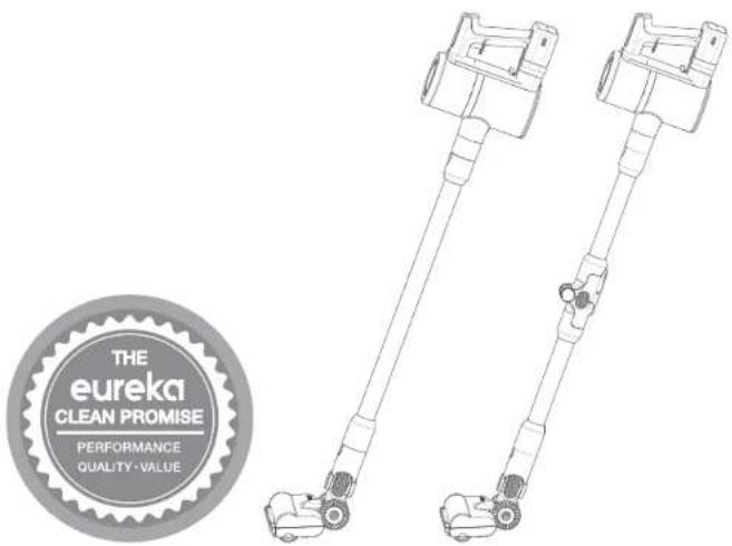
text_image
THE eureka CLEAN PROMISE PERFORMANCE QUALITY - VALUECordless Stick Vacuum Cleaner
AK10 SERIES
CONTENTS
Safety Precautions 3
Product Introduction 4
Installation of all parts 5
Disassembly of all parts 8
Function operation 10
Operation instructions 12
Cleaning and maintenance 14
ISAFETY PRECAUTIONS
Before using the appliance read all instructions and cautionary in this manual and on the appliance.
- Do not pick up wash detergent, kerosene, broken glass, needle, cigarettes, wet dust, sewage, match etc.
- Do not pick up small particle or large object like cement, land plaster, calcimine. Toy spitball, or cause model blocked, motor burned etc.
- Do not operate the vacuum cleaner too close to heaters, radiators and other hot surface.
- Never use the appliance without filters and brush roller in place.
- Never operate with blocked air inlet or blocked floor brush roller when using, or it may cause burned motor.
- Do not immerse the body of vacuum cleaner into water as this would Increase short circuit and burned model.
- New battery first or long time stocked running, battery must be fully charged.
- Long time no using, please keep charge/release electric per 3month. Please plug off when fully charged or cleaning or maintaining, do not stretcher pull the cable.
- Use dry cloth to clean the appliance and do not use petrol, lacquer Use dry cloth to clean the appliance and do not use petrol, lacquer thinner etc or surface of model is easy to be cracked and color fading.
- Please do not use and store the appliance in hot or cold environment
- Only operate in a dry indoor area where the temperature is more than 0°C but less than 40°C, prohibited long time exposure by sun.
- 1) This appliance can be used by children aged from 8 years and above and persons with reduced physical, sensory or mental capabilities or lack of experience and knowledge if they have been given supervision or instruction concerning use of the appliance in a safe way and understand the hazards involved. Children shall not play with the appliance. Cleaning and user maintenance shall not be made by children without supervision.
- Cleaning and user maintenance should not be made by children without supervision.
- If the appliance is not working when fully charged as it should, must be sent to maintenance station and checking, do not disassemble the appliance as incorrect reassembly may result in an electric shock or fire.
- Waste batter should be safely recycled. Do not throw away.
- Keep hair, loose clothing, fingers and all parts of body away from openings and moving parts.
- The appliance is only to be used with the power supply unit provided with the appliance
- 2) If a vacuum cleaner can be equipped with a hand-held accessory with rotating parts a warning has to be given concerning entrapment. 3
IPRODUCT INTRODUCTION
PRODUCT OVERVIEW
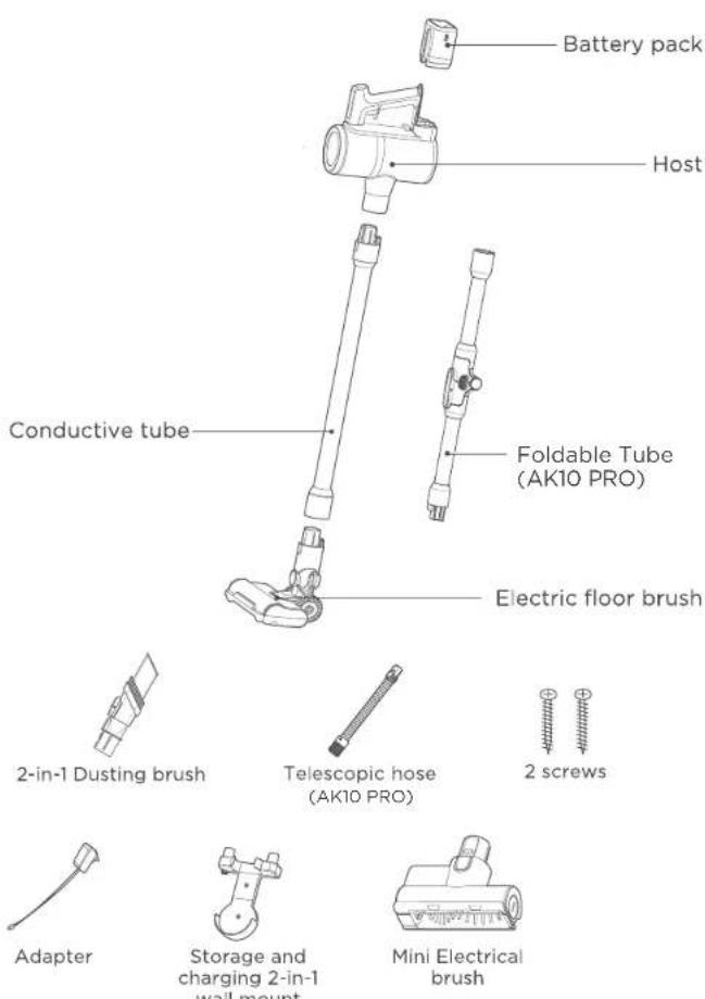
text_image
Battery pack Host Conductive tube Foldable Tube (AK10 PRO) Electric floor brush 2-in-1 Dusting brush Telescopic hose (AK10 PRO) 2 screws Adapter Storage and charging 2-in-1 wall mount Mini Electrical brushINSTALLATION OF ALL PARTS
1. Installation of HEPA component
Install the HEPA component and the air outlet plate component, and then install the motor cover component and screw it into place.
2. Installation of cyclone cone component
Put cyclone cone into dust cup, then insert filter cotton into cyclone cone.
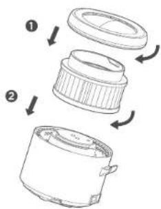
text_image
Diagram showing three-step assembly of a device with labeled parts and directional arrows indicating process flow.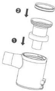
text_image
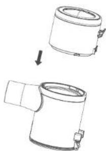
Technical diagram showing a pipe fitting with labeled parts and directional arrows indicating assembly steps.3. Installation of dust cup component
Insert motor cover component into the dust cup, and screw them.
4. Installation of handle component
Fasten the upper lock first, and then install the handle component.
natural_image
Diagram showing two views of a cylindrical mechanical component with a downward arrow indicating transformation (no text or symbols present)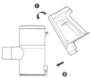
natural_image
Technical line drawing of a mechanical device with two views (① and ②), no text or symbols present.INSTALLATION OF ALL PARTS
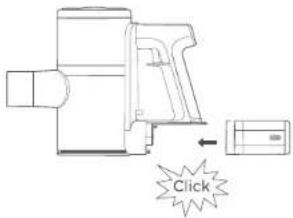
5. Installation of battery pack component
Insert the battery pack into the bottom of the machine until you hear a "click" lock sound. You shall pay attention to the direction.
6. Connection of metal tubes
When installing the metal tube component, insert the plug end of the metal tube into the socket of the handheld component until you hear a sound. "click" lock.
text_image
Click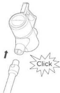
text_image
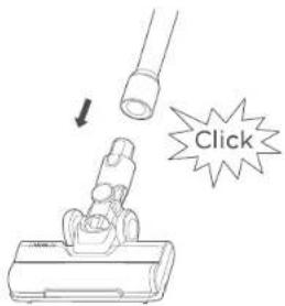
Click7. Connection of floor brush
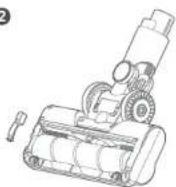
Insert the metal tube component into the floor brush until you hear a "click" lock sound.
8. Connect accessories with the handheld component
Insert the accessory into the handheld component until you hear a "click" lock sound.
text_image
Click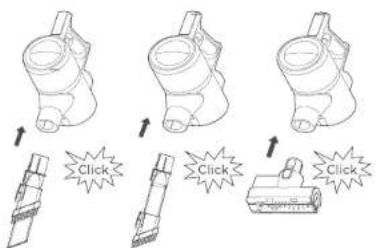
text_image
Diagram illustrating a mechanical or electrical component with four steps showing click actions and a separate schematic.INSTALLATION OF ALL PARTS
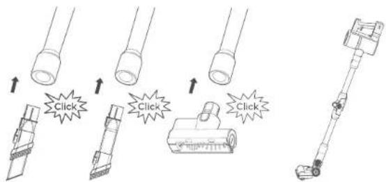
9. Connect accessories with the metal tube component
When the accessory is installed on the metal tube component, insert it into the metal tube component until you hear a "click" lock sound.
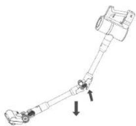
10. Introduction to the use of AK10 Pro bent pipe
1: Hold the machine with one hand and press the illustrated arrow button with the other hand;
text_image
Diagram illustrating how to press a cable or cable connector via clicking, with labeled arrows and starburst icons.11. Storage of the machine
2: Tilt the machine downward:
12. Storage of the machine
The wall mount is fixed on the wall by expansion screws. The rear of the .host is inserted into the wall mount to hang vertically. And the accessories are inserted into the accessory rack on the wall mount.
natural_image
Mechanical linkage diagram showing a lever system with two directional arrows indicating movement (no text or labels)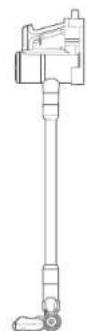
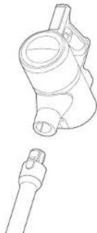
1. Disassembly of metal tube component
Press the lock button on the metal tube and pull out the metal tube.
natural_image
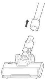
Technical line drawing of a mechanical component with two views (top and side), no text or symbols present.2. Disassembly of the floor brush component
Press and hold the lock button on the floor brush and pull out the metal tube.
natural_image
Line drawing of a mechanical device with a cylindrical component and an arrow indicating upward motion (no text or symbols)3. Disassembly of the battery pack
Press and hold the battery pack button, then pull out the battery pack.
4. Disassembly of handle component
Press the dust cup release button and pull out the handle component.
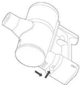
natural_image
Technical line drawing of a mechanical component with arrows indicating motion (no text or symbols)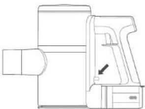
natural_image
Technical line drawing of a mechanical device with no visible text or symbolsPress the dust cup empty button, and the dust cup lid will pop to open and pour the ash.
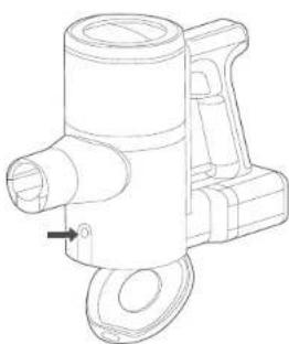
natural_image
Technical line drawing of a mechanical component with no visible text or symbolsIFUNCTION OPERATION
BATTERY CHARGING

CAUTION
- The battery is not charged when leaving the factory, please be sure to fully charge the battery before use.
- Do not charge in an environment below 5°C and above 40°C.
- When the product power is running low, the battery power indicator flashes to remind.
- When the battery life of the machine is obviously shortened, and the charging time becomes longer, please ask professionals to replace the battery. Please do not disassemble the machine by yourself to avoid danger.
5 Charge the battery pack.
The charging port is shown in the below figure.
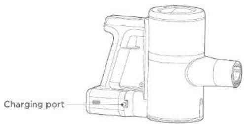
text_image
Charging portCHARGING INSTRUCTIONS

CAUTION
When you use this product for the first time, the battery capacity of the vacuum cleaner may not be full. You need to plug in the power adapter to fully charge the battery before it can be used. The about 4-5 hours, charging time is.
IFUNCTION OPERATION
CHARGING INSTRUCTIONS
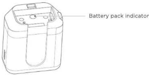
The battery pack can be charged separately, the battery charging indicator flashes to indicate that it is charging. When the indicator is always kept on, it indicates that the battery is fully charged (At this time, the charging is still going on for 0.5-1 hours, so the charging effect is better)
text_image
Battery pack indicatorCLEAN UP

CAUTION
- In order to avoid blocking the air duct, please clean up large pieces of garbage in the area (such as large pieces of paper and packaging film etc).
- Do not use and store the battery in an environment below 5°C and above 40°C.
- When you dispose of this product, please remove the battery from the machine.
- It is strictly forbidden to modify the machine, accessories, adapter or battery.
I OPERATION INSTRUCTIONS
Press the ON/OFF button, the machine runs and starts cleaning. Press the ON/OFF button again to shut down the machine and stop cleaning.
INTRODUCE OF OPERATING BUTTON
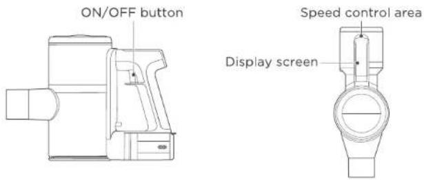
The machine adopts a trigger switch to start and shut down machine which is the ON/OFF button. And you can adjust three gears of Low/Medium/High by touching the speed control area. Information and status of battery and motor power will be shown on the display screen.
text_image
ON/OFF button Speed control area Display screenSTART
Press the power ON/OFF button, the machine starts at the Medium gear by default, at the moment, it can be used to clean the ground that needs to be cleaned routinely.
SPEED CONTROL
Touch the speed control area to switch to mid-gear, and then touch the speed control area again to switch to high-gear. The high-gear mode is generally used in areas that are difficult to clean, such as carpets and crevices. Touch the speed control area again to restore the low gear. The three gears are indicated on the display screen by the following icons.

Low

Medium

High
SHUT DOWN
Press the power ON/OFF button again to shut down the machine and stop cleaning.
I OPERATION INSTRUCTIONS
USE THE ELECTRIC FLOOR BRUSH
Electric floor brushes can be used for vacuuming on short-haired carpets or hard floors, floor tiles, and car seats and foot pads.
USE THE ACCESSORIES
- Insert the two-in-one accessory into the suction base, fix it and use it.
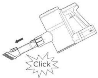
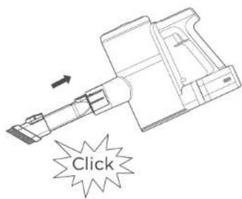
- Push the brush head of the two-in-one accessory back, and when you hear a "click" sound, it is fixed, it can clear gaps in corners, stairs and keyboards etc. Push the brush head of the two-in-one accessory forward, when you hear a "click" sound, it is fixed, you can clean the hard-to-clean places such as furniture, bookshelves and curtains.
text_image
Click- Push the brush head of the two-in-one accessory forward, when you hear a "clik" sound, it is fixed. It can clean up areas that are difficult to clean, such as furniture, bookshelves and curtains.
text_image
ClickICLEANING AND MAINTENANCE DUST CUP DISASSEMBLY AND CLEANING
CAUTION
To maintain the suction power of the vacuum cleaner, please clean up the dust regularly.
-
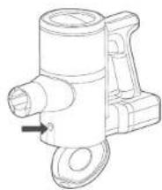
Press the dust cup empty button to pour out the dust.
-
Press the dust cup release button to remove the handle component.
natural_image
Technical line drawing of a mechanical component with no visible text or symbols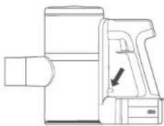
natural_image
Technical line drawing of a mechanical device with an arrow indicating a component (no text or symbols present)-
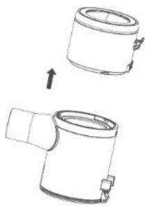
Rotate the motor cover component to remove the dust cup component.
-
Remove the filter cotton from the cyclone cone, and then take out cyclone cone from the dust cup component for cleaning.
natural_image
Technical line drawing of a cylindrical mechanical component with an arrow indicating assembly or transformation (no text or symbols present)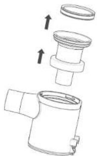
natural_image
Technical line drawing of a mechanical component with no visible text or symbolsICLEANING AND MAINTENANCE
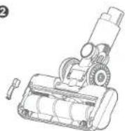
- Press the button to release the electric floor brush.
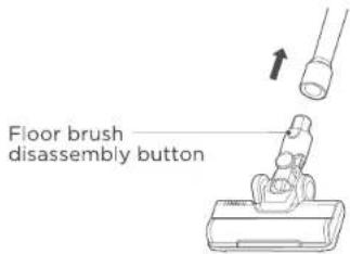
text_image
Floor brush disassembly button- Press the roller brush release lock to release the roller brush.
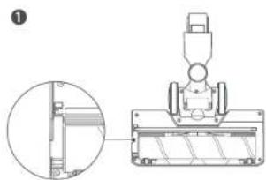
natural_image
Technical line drawing of a mechanical assembly with an inset close-up showing a cross-section (no text or symbols)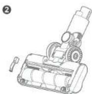
- Take out the brush roller from the slot and then clean it up.
- After cleaning or replacement, assemble in the reverse order of disassembly and reset the cover of brush roller.
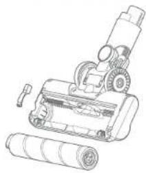
natural_image
Line drawing of a microscope with a rolled roller and mechanical components (no text or symbols)| CORRECT DISPOSAL OF THIS PRODUCT | |
 | Remove the battery before the device is disposed of and dispose of it separatelyrom the device at suitable collection points. |
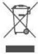 | This device is governed by the EuropeanDirective 2012 / 19 / EU on waste electricaland electron-ic equipment (WEEE) Do notdispose of the device as normal domestic waste, but rather in an environmentally friendly manner via an officially approvedwaste disposal company. |
WARNINGS
This appliance contains batteries that are only replaceable by skilledpersonsThe floor brush of the product is a moving part. Be careful of your feet or other things being caught.
We Offer 2-Year Limited Warranty.
Email Our Customer Service:
global_service@eureka.com
Our Official Site:
https://www.eureka.com/uk
https://www.eureka.com/de
eureka
SEIT 1909
eureka
Bedienungsanleitung
text_image
Diagram showing two steps of a mechanical device with labeled parts and directional arrows indicating rotation or assembly.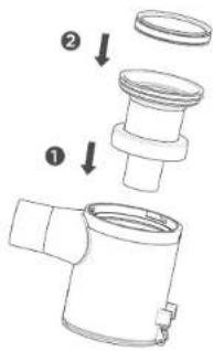
text_image
Technical diagram showing a pipe fitting with labeled parts and directional arrows indicating assembly steps.natural_image
Diagram showing a cylindrical mechanical component being dropped, with an arrow indicating the process (no text or symbols present)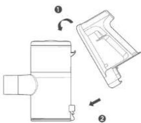
natural_image
Technical line drawing of a mechanical device with two views (① and ②), no text or symbols present.I MONTAGE ALLER TEILE
5. Installation des Akkupacks
text_image
Diagram illustrating how to press a rubber can into a rubber plug, with labeled components and directional arrows.IMONTAGE ALLER TEILE
natural_image
Mechanical linkage diagram showing a curved joint with two directional arrows indicating movement (no text or labels)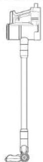
I DEMONTAGE ALLER TEILE DEMONTAGE ALLER TEILE
natural_image
Technical line drawing of a mechanical component with two views (top and side), no text or symbols present.natural_image
Line drawing of a hairdryer with a cable attachment (no text or symbols)3. Demontage des Akkupacks
natural_image
Technical line drawing of a mechanical component with arrows indicating motion (no text or symbols)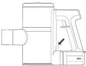
natural_image
Technical line drawing of a mechanical device with no visible text or symbolsnatural_image
Technical line drawing of a mechanical component with no visible text or symbolsIBETRIEB
LADEN DES AKKUS

VORSICHT
natural_image
Technical line drawing of a mechanical component with no visible text or symbolsnatural_image
Technical line drawing of a mechanical device with an arrow indicating a component (no text or symbols present)natural_image
Diagram showing two views of a cylindrical mechanical component with an arrow indicating direction (no text or symbols)natural_image
Technical line drawing of a mechanical component with arrows indicating assembly or transformation (no text or symbols)natural_image
Technical line drawing of a mechanical assembly with an inset close-up showing a detail (no text or symbols)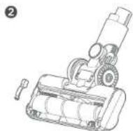
natural_image
Line drawing of a mechanical device with gears and rollers (no text or symbols)text_image
Diagram showing three-step assembly of a mechanical component with numbered callouts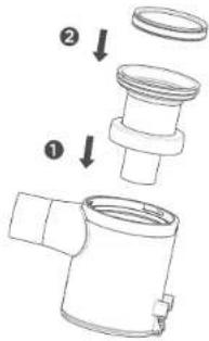
text_image
Technical diagram showing a pipe fitting with labeled steps ① and ②, indicating assembly or installation.natural_image
Diagram showing two mechanical components with a downward arrow indicating transformation (no text or symbols present)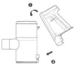
natural_image
Technical line drawing of a mechanical device with two views (① and ②), no text or symbols present.INSTALLATION DES PIÈCES INSTALLATION DES PIÈCES
text_image
Diagram illustrating three-step mechanical assembly or assembly process with labeled 'Clic' and directional arrows indicating sequence.text_image
Diagram illustrating the process of cable assembly with labeled components and explosion effects11. Stockage de la machine
natural_image
Mechanical linkage diagram showing a curved mechanical assembly with two directional arrows indicating movement (no text or labels)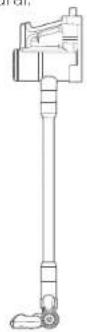
I DÉMONTAGE DES PIÈCES DÉMONTAGEIDES PIÈCES
natural_image
Technical line drawing of two mechanical components (no text or symbols)natural_image
Diagram showing a device being inserted into a cable with an arrow indicating the insertion direction (no text or symbols present)natural_image
Technical line drawing of a mechanical component with arrows indicating motion or assembly (no text or symbols)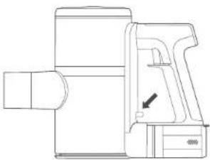
natural_image
Technical line drawing of a mechanical device with no visible text or symbolsnatural_image
Technical line drawing of a mechanical component with no visible text or symbolsI UTILISATION DES FONCTIONS
CHARGE DE LA BATTERIE

ATTENTION
natural_image
Technical line drawing of a mechanical component with no visible text or symbolsnatural_image
Technical line drawing of a mechanical device with no visible text or symbolsnatural_image
Diagram showing two mechanical components with an arrow indicating transformation (no text or symbols present)natural_image
Technical line drawing of a mechanical component with arrows indicating assembly or transformation (no text or symbols)natural_image
Technical line drawing of a mechanical assembly with an inset close-up view (no text or symbols)②
natural_image
Line drawing of a mechanical device with gears and a rolled sheet (no text or symbols)text_image
Diagram showing three-step assembly of a mechanical component with numbered parts and directional arrows indicating motion.
text_image
Technical diagram showing a pipe fitting with labeled parts and directional arrows indicating assembly steps.natural_image
Diagram showing two views of a cylindrical mechanical component with an arrow indicating transformation (no text or symbols present)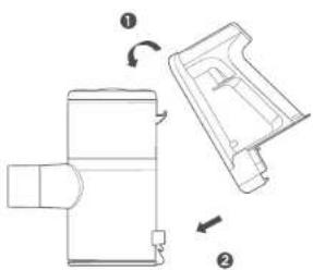
natural_image
Technical line drawing of a mechanical device with two views (① and ②), no text or symbols present.I MONTAGGIO DI TUTTE LE PARTI MONTAGGIO DI TUTTE LE PARTI
text_image
Diagram illustrating three-step instructions for inserting a Clic (click) pen, showing step-by-step assembly.text_image
Diagram illustrating the process of a cable or cable connector with labeled components and explosion effectsnatural_image
Mechanical linkage diagram showing a curved joint with two directional arrows indicating movement (no text or labels)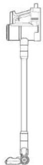
I SMONTAGGIO DI TUTTE LE PARTI SMONTAGGIO DI TUTTE LE PARTI
natural_image
Technical line drawing of a mechanical component with two views (top and side), no text or symbols present.natural_image
Diagram showing a mechanical assembly with a pipe and a base component, no text or symbols presentnatural_image
Technical line drawing of a mechanical component with arrows indicating motion (no text or symbols)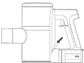
natural_image
Technical line drawing of a mechanical device with no visible text or symbolsnatural_image
Technical line drawing of a mechanical component with no visible text or symbolsnatural_image
Line drawing of a portable electronic device with a handle and top panel (no text or symbols)natural_image
Technical line drawing of a mechanical device with no visible text or symbolsnatural_image
Technical line drawing of a mechanical component with no visible text or symbolsnatural_image
Technical line drawing of a mechanical device with no visible text or symbolsnatural_image
Diagram showing two mechanical components with an arrow indicating transformation (no text or symbols)natural_image
Technical line drawing of a mechanical component with arrows indicating assembly direction (no text or symbols)natural_image
Technical line drawing of a mechanical assembly with an inset close-up view (no text or symbols)②
natural_image
Line drawing of a mechanical device with gears and a rolled-up battery (no text or symbols)text_image
Diagram showing three-step assembly of a mechanical component with numbered parts and directional arrows indicating motion.
text_image
Technical diagram showing a pipe fitting with labeled parts and directional arrows indicating assembly steps.natural_image
Technical line drawing of a mechanical component with two views (top and side), showing a transformation or assembly process (no text or symbols present)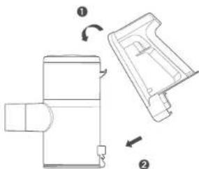
natural_image
Technical line drawing of a mechanical device with two views (① and ②), no text or symbols present.text_image
Diagram illustrating three-step mechanical assembly or assembly process with click instructions and directional arrows indicating movement.text_image
Diagram illustrating the process of a cable or cable switch with labeled components and warning symbolsnatural_image
Mechanical linkage diagram showing a curved assembly with directional arrows (no text or labels)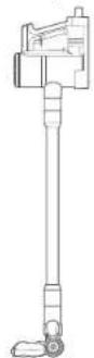
I DESMONTAJE DE TODAS LAS PIEZAS DESMONTAJE DE TODAS LAS PIEZAS
natural_image
Technical line drawing of two mechanical components (no text or symbols)natural_image
Diagram showing a device with a cylindrical component being inserted into it, with an arrow indicating the process (no text or symbols present)natural_image
Technical line drawing of a mechanical component with arrows indicating motion or assembly (no text or symbols)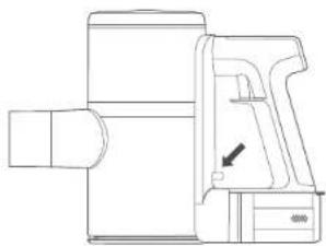
natural_image
Technical line drawing of a mechanical component with no visible text or symbolsnatural_image
Technical line drawing of a mechanical component with no visible text or symbolsnatural_image
Technical line drawing of a mechanical component with no visible text or symbolsnatural_image
Technical line drawing of a mechanical device with no visible text or symbolsnatural_image
Diagram showing two mechanical components with an arrow indicating transformation (no text or symbols present)natural_image
Technical line drawing of a mechanical component with arrows indicating assembly direction (no text or symbols)natural_image
Technical diagram of a mechanical assembly with an inset close-up showing a component detail (no text or symbols present)