
YWMBT7030SV - Oven WHIRLPOOL - Free user manual and instructions
Find the device manual for free YWMBT7030SV WHIRLPOOL in PDF.


User questions about YWMBT7030SV WHIRLPOOL
0 question about this device. Answer the ones you know or ask your own.
Ask a new question about this device
Download the instructions for your Oven in PDF format for free! Find your manual YWMBT7030SV - WHIRLPOOL and take your electronic device back in hand. On this page are published all the documents necessary for the use of your device. YWMBT7030SV by WHIRLPOOL.
USER MANUAL YWMBT7030SV WHIRLPOOL
BUILT-IN MICROWAVE OWNER'S MANUAL MANUEL DU PROPRIÉTAIRE DU FOUR À MICROONDES ENCASTRÉ
Table of Contents/Table des matières
MICROWAVE OVEN SAFETY....2
Microwave Oven Safety 2
Internet Connection Guide for Connected Appliances Only .....4
FCC Caution....5
PRECAUTIONS TO AVOID POSSIBLE EXPOSURE
TO EXCESSIVE MICROWAVE ENERGY....5
PRECAUTIONS TO AVOID POSSIBLE EXPOSURE
TO EXCESSIVE MICROWAVE ENERGY....5
MICROWAVE OVEN MAINTENANCE AND CARE....6
General Cleaning....6
INSTALLATION INSTRUCTIONS REQUIREMENTS ...... 6
Tools and Parts 6
Product Dimensions 7
Location Requirements 7
Electrical Requirements 11
INSTALLATION INSTRUCTIONS 11
Prepare Microwave Oven 11
Install the Rails-Standard.... 11
Install the Rails-Flush 12
Install the brackets (for flush installation only).... 14
Install the Microwave Oven 15
Fasten the Microwave Oven-Standard 15
Fasten the Microwave Open-Flush 16
COMPLETE INSTALLATION 16
Complete Installation 16
SÉCURITÉ DU FOUR À MICRO-ONDES 17
text_image
Black and white barcode image with vertical lines and dots, no readable text or symbolsW11739861B
Your safety and the safety of others are very important.
We have provided many important safety messages in this manual and on your appliance. Always read and obey all safety messages.

This is the safety alert symbol.
This symbol alerts you to potential hazards that can kill or hurt you and others.
All safety messages will follow the safety alert symbol and either the word "DANGER" or "WARNING." These words mean:
DANGER
WARNING
You can be killed or seriously injured if you don't immediately follow instructions.
You can be killed or seriously injured if you don't follow instructions.
All safety messages will tell you what the potential hazard is, tell you how to reduce the chance of injury, and tell you what can happen if the instructions are not followed.
IMPORTANT SAFETY INSTRUCTIONS
When using electrical appliances basic safety precautions should be followed, including the following:
WARNING: To reduce the risk of burns, electric shock, fire, injury to persons, or exposure to excessive microwave energy:
- Read all instructions before using the appliance.
- Read and follow the specific "PRECAUTIONS TO AVOID POSSIBLE EXPOSURE TO EXCESSIVE MICROWAVE ENERGY" found in the PRECAUTIONS TO AVOID POSSIBLE EXPOSURE TO EXCESSIVE MICROWAVE ENERGY section.
This appliance must be grounded. Connect only to properly grounded outlet. See "GROUNDING INSTRUCTIONS" section.
■ Install or locate this appliance only in accordance with the provided Installation Instructions.
■ Some products such as whole eggs and sealed containers - for example, closed glass jars - are able to explode and should not be heated in this oven.
■ Use this appliance only for its intended use as described in the manual. Do not use corrosive chemicals or vapors in this appliance. This type of oven is specifically designed to heat, cook, or dry food. It is not designed for industrial or laboratory use.
■ HOT CONTENTS CAN CAUSE SEVERE BURNS. DO NOT ALLOW CHILDREN TO USE THE MICROWAVE. Use caution when removing hot items.
■ Do not operate this appliance if it has a damaged cord or plug, if it is not working properly, or if it has been damaged or dropped.
■ This appliance should be serviced only by qualified service personnel. Contact nearest authorized service facility for examination, repair, or adjustment.
■ Do not cover or block any openings on the appliance. - Do not store this appliance outdoors. Do not use this product near water – for example, near a kitchen sink, in wet basement, near a swimming pool, or similar locations.
■ Do not immerse cord or plug in water.
- Keep cord away from heated surfaces.
■ Do not let cord hang over edge of table or counter.
■ Do not use replacement parts that have not been recommended by the manufacturer (e.g. parts made at home using a 3D printer).
■ See door surface cleaning instructions in the "Microwave Oven Maintenance and Care" section.
- Liquids, such as water, coffee, or tea are able to be overheated beyond the boiling point without appearing to be boiling. Visible bubbling or boiling when the container is removed from the microwave oven is not always present. THIS COULD RESULT IN VERY HOT LIQUIDS SUDDENLY BOILING OVER WHEN THE CONTAINER IS DISTURBED OR A UTENSIL IS INSERTED INTO THE LIQUID.
■ Do not operate any heating or cooking appliance beneath this appliance.
■ Do not mount unit over or near any portion of a heating or cooking appliance.
■ Do not mount over a sink.
■ Do not store anything directly on top of the appliance surface when the appliance is in operation.
■ Clean Ventilating Hoods Frequently - Grease should not be allowed to accumulate on hood or filter.
■ When flaming foods under the hood, turn the fan on.
■ Suitable for use above electric cooking equipment.
■ Intended to be used above ranges with maximum width of 36" (91.44 cm).
■ Do not touch or clean the heating plate after toast cooking, it is very hot.
SAVE THESE INSTRUCTIONS
IMPORTANT SAFETY INSTRUCTIONS
When using electrical appliances basic safety precautions should be followed, including the following:
WARNING: To reduce the risk of burns, electric shock, fire, injury to persons, or exposure to excessive microwave energy:
■ Use care when cleaning the vent-hood filter. Corrosive cleaning agents, such as lye-based oven cleaners, may damage the filter.
■ To reduce the risk of fire in the oven cavity:
- Do not overcook food. Carefully attend appliance when paper, plastic, or other combustible materials are placed inside the oven to facilitate cooking.
- Remove wire twist-ties from paper or plastic bags before placing bag in oven.
- If materials inside the oven ignite, keep oven door closed, turn oven off, and disconnect the power cord, or shut off power at the fuse or circuit breaker panel.
- Do not use the cavity for storage purposes. Do not leave paper products, cooking utensils, or food in the cavity when not in use.
■ Oversized foods or oversized metal utensils should not be inserted in a microwave/toaster oven as they may create a fire or risk of electric shock.
■ Do not clean with metal scouring pads. Pieces can burn off the pad and touch electrical parts involving a risk of electric shock.
■ Do not use paper products when appliance is operated in the toaster mode.
- Do not store any materials, other than manufacturer's recommended accessories, in this oven when not in use.
■ Do not cover racks or any other part of the oven with metal foil. This will cause overheating of the oven.
SAVE THESE INSTRUCTIONS
Internet Connectivity Guide for Connected Appliances Only
IMPORTANT: Proper installation of your appliance prior to use is your responsibility. Be sure to read and follow the installation instructions that came with your appliance.
Connectivity requires Wi-Fi and account creation. App features and functionality are subject to change. Data rates may apply. Once installed, launch the app. You will be guided through the steps to set up a user account and to connect your appliance.
You Will Need:
A home wireless router supporting Wi-Fi, 2.4 Ghz with WPA2 security. If you are unsure of your router's capabilities, refer to the router manufacturer's instructions.
■ The router to be on and have a live internet connection.
■ The 10-character SAID code for your appliance. The SAID code is either printed on a label on the appliance or found on the LCD screen.
Federal Communications Commission (FCC) Compliance Notice
This device complies with Part 15 of the FCC Rules. Operation is subject to the following two conditions:
-
This device may not cause harmful interference, and
-
This device must accept any interference received, including interference that may cause undesired operation.
Changes or modifications not expressly approved by the party responsible for compliance could void the user's authority to operate the equipment.
Industry Canada (IC) Compliance Notice
This Device complies with Industry Canada License-exempt RSS standard(s). Operation is subject to the following two conditions:
- This device may not cause interference.
- This device must accept any interference, including interference that may cause undesired operation of the device.
Under Industry Canada regulations, this radio transmitter may only operate using an antenna of a type and maximum (or lesser) gain approved for the transmitter by Industry Canada. To reduce potential radio interference to other users, the antenna type and its gain should be so chosen that the equivalent isotropically radiated power (e.i.r.p.) is not more than that necessary for successful communication.
To comply with FCC and Industry Canada RF radiation exposure limits for general population, antenna(s) used for this transmitter must be installed such that a minimum separation distance of 20 cm is maintained between the radiator (antenna) and all persons at all times and must not be co-located or operating in conjunction with any other antenna or transmitter.
If this equipment does cause harmful interference to radio or television reception, which can be determined by turning the equipment off and on, the user is encouraged to try to correct the interference by one of the following measures:
■ Reorient or relocate the receiving antenna.
■ Increase the separation between the equipment and receiver.
■ Connect the equipment into an outlet on a circuit different from that to which the receiver is connected.
■ Consult the dealer or an experienced radio/TV technician for help.
FCC Caution
■ Changes or modifications not expressly approved by Whirlpool Corporation could void the user's authority to operate the equipment.
The antenna(s) used for this transmitter must be installed such that a minimum separation distance of 20 cm is maintained between radiator (antenna) and all persons at all times and must not be co-located or operating in conjunction with any other antenna or transmitter.
Part 15B compliance statements for digital devices:
NOTE: This equipment has been tested and found to comply with the limits for a Class B digital device, pursuant to Part 15 of the FCC Rules. These limits are designed to provide reasonable protection against harmful interference in a residential installation. This equipment generates; uses and can radiate radio frequency energy and, if not installed and used in accordance with the instructions, may cause harmful interference to radio communications. However, there is no guarantee that interference will not occur in a particular installation. If this equipment does cause harmful interference to radio or television reception, which can be determined by turning the equipment off and on, the user is encouraged to try to correct the interference by one of the following measures:
■ Reorient or relocate the receiving antenna.
■ Increase the separation between the equipment and receiver.
■ Connect the equipment into an outlet on a circuit different from that to which the receiver is connected.
■ Consult the dealer or an experienced radio/TV technician for help.
The user manual for the end product must include the following information in a prominent location Instruction
"To comply with FCC RF radiation exposure limits for general population, the antenna(s) used for this transmitter must be installed such that a minimum separation distance of 20 cm is maintained between the radiator (antenna) and all persons at all times and must not be co-located or operating in conjunction with any other antenna or transmitter."
OEM Responsibilities to comply with FCC Regulations
The rebel UI Modules have been certified for integration into products only by OEM integrators under the following conditions:
- The antenna(s) must be installed such that a minimum separation distance 20 cm is maintained between the radiator (antenna) and all persons at all times.
- The transmitter module must not be co-located or operating in conjunction with any other antenna or transmitter.
As long as the two conditions above are met, further transmitter testing will not be required. However, the OEM integrator is still responsible for testing their end-product for any additional compliance requirements required with this module installed (for example, digital device emissions, PC peripheral requirements, etc.)
IMPORTANT: In the event that these conditions cannot be met (for certain configurations or co-location with another transmitter), then the FCC authorizations are no longer considered valid and the FCC ID cannot be used on the final product. in these circumstances, the OEM integrator will be responsible for re-evaluating the end product (including the transmitter) and obtaining a separate FCC authorization.
End Product Labelling
This module is labelled with an FCC ID. If the FCC ID is not visible when the module is installed inside another device, then the outside of the device into which the module is installed must also display a label referring to the enclosed module. In that case, the final end product must be labelled in a visible area or display the following:
"Contains FCC ID: 2AC7Z-RIGEL"
The OEM of this module must only use the approved antenna(s), which have been certified with this module. The OEM integrator has to be aware not to provide information to the end user regarding how to install or remove this RF module or change RF related parameters in the user manual of the end product.
PRECAUTIONS TO AVOID POSSIBLE EXPOSURE TO EXCESSIVE MICROWAVE ENERGY
(a) Do not attempt to operate this oven with the door open (s) do not operate the oven if it is damaged. It is particularly open-door operation can result in harmful exposure to important that the oven door close properly and that there is microwave energy. It is important not to defeat or tamper with damage to the: the safety interlocks. (1) Door (bent)
(b) Do not place any object between the oven front face and the Hinges and latches (broken or loosened), door or allow soil or cleaner residue to accumulate on sealing. Door seals and sealing surfaces surfaces.
(d) The oven should not be adjusted or repaired by anyone except properly qualified service personnel.
IMPORTANT: Before cleaning, make sure all controls are off and the microwave oven is cool. Always follow label instructions on cleaning products.
Soap, water, and a soft cloth or sponge are suggested first, unless otherwise noted.
STAINLESS STEEL AND BLACK STAINLESS STEEL (on some models)
NOTE: To avoid damage to stainless steel surfaces, do not use soap-filled scouring pads, abrasive cleaners, Cooktop Cleaner, steel-wool pads, gritty washcloths, or abrasive paper towels. Damage may occur to stainless steel surfaces, even with one-time or limited use.
Rub in direction of grain to avoid damaging.
Cleaning Method:
■ Affresh ^®† Stainless Steel Cleaners Part Number W10355016 (not included) or affresh ^® Stainless Steel Cleaning Wipes Part Number W1055049 (not included): See the Quick Start Guide for ordering information.
■ Vinegar for hard water spots.
MICROWAVE OVEN DOOR EXTERIOR
Cleaning Method:
■ Glass cleaner and a soft cloth or sponge: Apply glass cleaner to soft cloth or sponge, not directly on panel.
■ Affresh ^® Kitchen Appliance Cleaners Part Number W10355010 (not included): See “Online Ordering Information” section from Quick Start Guide to order.
NONSTICK CAVITY COATING (on some models)
To avoid damage to the microwave oven cavity, do not use metal or sharp utensils or scrapers or any type of abrasive cleanser or scrubbers.
To avoid damage to the microwave oven cavity, do not use soap-filled scouring pads, abrasive cleaners, steel-wool pads, gritty washcloths, or some paper towels.
On stainless steel models, rub in direction of grain to avoid damaging.
The area where the microwave oven door and frame touch when closed should be kept clean.
Cleaning Method:
Average soil
■ Mild, nonabrasive soaps and detergents: Rinse with clean water and dry with soft, lint-free cloth.
Heavy soil
■ Mild, nonabrasive soaps and detergents: Heat 1 cup (250 mL) of water for 2 to 5 minutes in microwave oven. Steam will soften soil. Rinse with clean water and dry with soft, lint-free cloth.
Odors
■ Lemon juice or vinegar: Heat 1 cup (250 mL) of water with 1 tbs (15 mL) of either lemon juice or vinegar for 2 to 5 minutes in microwave oven.
Wire Rack
■ Steel-wool pad
■ Dishwasher
†affresh ^® is a registered trademark of Whirlpool, U.S.A.
Toast Pan (on some models)
■ Mild cleanser and scouring pad
■ Dishwasher
Air Fry Basket
■ Steel-wool pad
■ Dishwasher
Embedded Heating Plate (on some models)
■ Glass cleaner and a soft cloth or sponge
There is an embedded heating plate under the oven bottom on some models. After some cooking, the oven bottom glass becomes very hot (see "Online control guide" for more details). Clean the glass after the "Oven too hot" disappeared on the display.
Probe (on some models)
■ Soap and warm water
The probe is a hand wash only item. Hold onto the rubber end, gently wash with soap and warm water. Rinse and dry well before storing. Place in a provided storage box for easy access. Keep the storage box clean of food and residue. See Quick Start Guide for more information.
INSTALLATION INSTRUCTIONS REQUIREMENTS
Tools and Parts
Tools Needed
■ Measuring tape
■ Pencil
Drill
■ Phillips screwdriver
■ 7/64" drill bit
Screws Supplied (not shown to scale)
| Part Part art Total | Qty | Standard Qty | Flush Qty | |
| #7-16x 7/16" round-head wood screw | 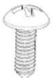 | 14 | 6 | 10 |
| #7-16x 15/16" flat head wood screw | [2057] | 4 | 2 | / |
| M4x1/2" flat head self-tapping screw | 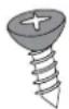 | 4 | / | 2 |
NOTE: Some are spare screws. Different installation methods require different numbers of screws. Please refer to the above table for specific quantities. The extra screws can be saved for use.
Parts Supplied (Standard) (not shown to scale)
| Part Part art | Qty | Where can find? | |
| Rail | 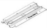 | 2 Outer foam | |
| Literature Pack |  | 1 | Outer foam |
| Screw hole cover |  | 2 | Literature pack |
Parts Supplied (Flush) (not shown to scale)
| Part Part art | Qty Where | can find? | |
| Rail |  | 2 Outer foam | |
| Literature Pack |  | 1 Outer foam | |
| Bracket L | 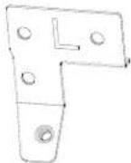 | 1 | Literature pack |
| Bracket R | 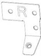 | 1 | Literature pack |
| Screw hole cover |  | 2 | Literature pack |
Check local codes. Check existing electricity. See "Electrical Requirements". It is recommended that all electrical connections be made by a licensed, qualified electrical installer.
NOTE:
■ The hardware items listed here are for wood studs. For other types of wall structures, be sure to use appropriate fasteners.
■ Be sure to purchase only Whirlpool factory-certified parts and accessories for your appliance. Your installation may require additional parts. To order, see the "Online Ordering Information" section of the Quick Start Guide.
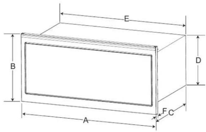
Product Dimensions
text_image
E B D A F C| Unit Measurement in | cm | ||
| A Width | of unit 29 | 7/8 | 76 |
| B | Height of unit | 185/8 | 47.3 |
| C | Depth of unit | 123/4 | 32.3 |
| D | Height of unit w/o door and vent | 163/8 | 31.5 |
| E | Width of unit w/o door and vent | 283/8 | 72 |
| F | Door and vent thickness | 13/8 | 3.5 |
Location Requirements
This is a built-in appliance. Do not use as countertop microwave oven.
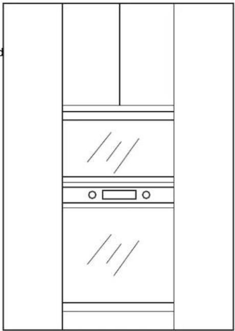
This microwave oven must be installed into a wood cabinetry. The location must provide:
■ Cutout opening that is plumb and square.
■ Cutout floor that is solid, level and flush with bottom of cabinet cutout.
■ Support for weight of 150 lbs (68 kg) which includes microwave oven and items placed inside the microwave oven and upper cabinet.
■ There must be minimum of 36" from the floor to cut-out floor. See pictorial below.
■ Grounded electrical outlet inside upper cabinet. See the "Electrical Requirements" section.
■ Minimum installation clearances for installation location. See "Required Cutout Dimensions" section.
■ Complete enclosure around the recessed portion of the microwave oven.
■ Mounting distance between a fixed wall on the hinged-side of the door and the microwave oven is 0.5" (1.3 cm).
Depending on your model, YWMBT7030 and YKMBT730 factory default setting are standard installation, YJOETC330 factory default setting is flush installation, choose one installation type before installation.
If you want to change to another installation method, you can order the installation kit online.
Flush installation kit #: W11740454 (Manufactured by Whirlpool)
Standard installation kit #: W11740456 (Manufactured by Whirlpool)
If your product has been installed, and you want to change to another installation method, uninstall the microwave and rails before installation.
To order, see the "Online Ordering Information" section of the Quick Start Guide.
For cabinets with other dimension's, we suggest selecting other Whirlpool Products.
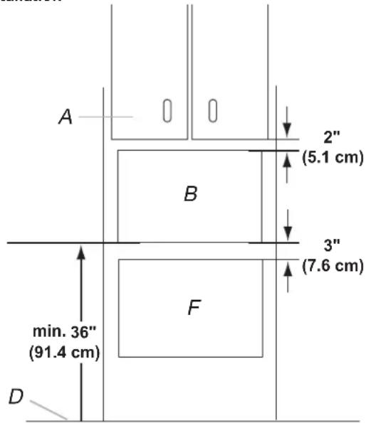
Cabinet Dimensions - Over A Built-In Oven, Standard Installation
text_image
A B 2" (5.1 cm) 3" (7.6 cm) min. 36" (91.4 cm) DA. Upper cabinet
B. Microwave oven cutout
C. Floor
D. Lower oven cutout
- Minimum distance of 36" (91.4 cm) from the floor to the cutout floor.
- The microwave oven may be installed over a built-in oven. If installing over a built-in oven, make sure there is a minimum of 3" (7.6 cm) between the top of the lower oven cutout and the microwave oven cutout floor.
- Make sure the surrounding cabinetry has clearance to open and close freely. Allow a clearance of at least 2" (5.1 cm) above the cutout opening.
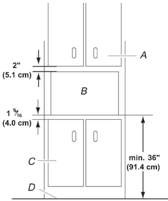
Cabinet Dimensions - Not Over A Built-In Oven, Standard Installation
text_image
2" (5.1 cm) B 1 9/16 (4.0 cm) C D A min. 36" (91.4 cm)A. Upper cabinet
B. Microwave oven cutout
C. Lower cabinet
D. Floor
- Minimum distance of 36" (91.4 cm) from the floor to the cutout floor.
-
The microwave oven may also be installed in a cabinet by itself (without a built-in oven below). Allow a clearance of at least 116 " (4.0 cm) below the cabinet.
-
Make sure the surrounding cabinetry has clearance to open and close freely. Allow a clearance of at least 2" (5.1 cm) above the cutout opening.
Cabinet Dimensions - Over A Built-In Oven, Flush Installation Cabinet Dimensions - Not Over A Built-In Oven, Flush Installation
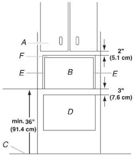
text_image
A F E B min. 36" (91.4 cm) C 2" (5.1 cm) E 3" (7.6 cm) DA. Upper cabinet
B. Microwave oven cutout
C. Floor
D. Lower oven cutout
E. 11/16" (1.75 cm) side cleat*
F. 1" (2.5 cm) top cleat*
- Minimum distance of 36" (91.4 cm) from the floor to the cutout floor.
- The microwave oven may be installed over a built-in oven. If installing over a built-in oven, make sure there is a minimum of 3" (7.6 cm) between the top of the lower oven cutout and the microwave oven cutout floor.
- Make sure the surrounding cabinetry has clearance to open and close freely. Allow a clearance of at least 2" (5.1 cm) above the cutout opening.
- *Cleats must be recessed ^3/8 " (3.5 cm) from the front of the cabinet. Cleats depth must be less than 2" (5.1 cm).
- The blocking of the *cleats are not glued and nailed into place. This allows for any necessary correction.
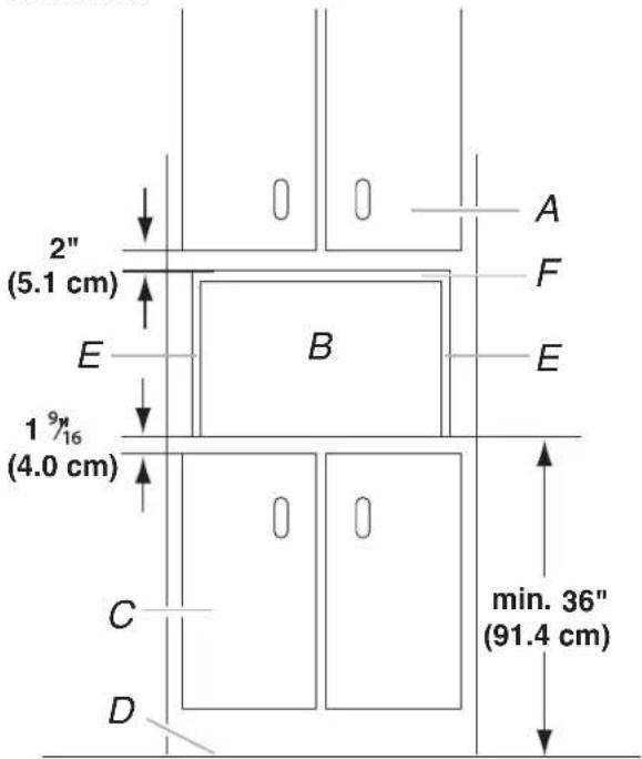
text_image
2" (5.1 cm) E B 19/16 (4.0 cm) C D min. 36" (91.4 cm) A F EA. Upper cabinet
B. Microwave oven cutout
C. Lower cabinets
D. Floor
E. 11/16" (1.75 cm) side cleat*
F. 1" (2.5 cm) top cleat*
- Minimum distance of 36" (91.4 cm) from the floor to the cutout floor.
- The microwave oven may also be installed in a cabinet by itself (without a built-in oven below). Allow a clearance of at least P_16 (4.0 cm) below the cabinet.
- Make sure the surrounding cabinetry has clearance to open and close freely. Allow a clearance of at least 2" (5.1 cm) above the cutout opening.
- *Cleats must be recessed ^3/1 " (3.5 cm) from the front of the cabinet. Cleats depth must be less than 2" (5.1 cm).
Required Cutout Dimensions- Standard
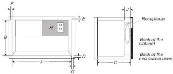
text_image
F B H E D A G J Receptacle Back of the Cabinet Back of the microwave oven C| Cabinet cutout measurement in | cm | ||
| A Width of cabinet opening | 28^1/2 | 72.4 | |
| B Height of cabinet opening | 17^1/8 | 43.5 | |
| C Depth of cabinet opening (min.) (with flush receptacle) | 16^3/4 | 42.5 | |
| D Frame overlap-lower frame | 7/16 | 1.1 | |
| E Frame overlap-upper frame | 1 2.5 | ||
| F Frame overlap-left frame | 11/16 1.8 | ||
| G Frame overlap-right frame | 11/16 1.8 | ||
| J Receptacle surface to the back of the microwave oven | 4 ~ 40 | 10.2 ~ 102 | |
NOTE:
■ Flush receptacle is recommended. For non-flush receptacle, make sure you have at least 4" (10.2 cm) clearance between the back of microwave oven and the receptacle.
If the receptacle is placed outside of the recommended region, make sure from the back of the microwave oven to the receptacle must be within 40" (102 cm). Otherwise, the power cord is not long enough to plug in.
■ Tolerance for width and height of cabinet opening is 1/16" (2 mm).
Required Cutout Dimensions-Flush
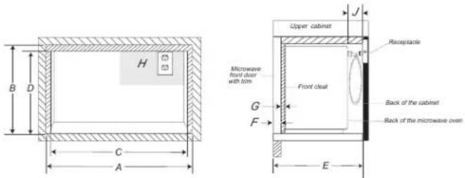
text_image
Upper cabinet Receptacle Upper cabinet with trim Front clean Back of the cabinet Back of the microwave oven Upper cabinet with trim G F E C A B D H 53| Cabinet cutout measurement in | cm | ||
| A Width of flush inset cutout (minimum) | 30 | 76.2 | |
| B | Height of flush inset cutout (minimum) | 18^15/_16 | 48 |
| C | Width of cabinet opening (minimum) | 28^5/_8 | 72.7 |
| D Height of cabinet opening (minimum) | 17^15/_16 | 45.5 | |
| E | Depth of cutout(min.) (with flush receptacle) | 18^3/_16 | 46.2 |
| F Cleat recessed from the front of the cabinet | 13/_8 | 3.5 | |
| G | Depth of the cleat (maximum) | 25.1 | |
| H | Receptacle area | / | / |
| J Receptacle surface to the back of the microwave oven | 4~40 10.2~102 | ||
NOTE:
■ Flush receptacle is recommended. For non-flush receptacle, make sure you have at least 4" (10.2 cm) clearance between the back of microwave oven and the receptacle.
If the receptacle is placed outside of the recommended region, make sure from the back of the microwave oven to the receptacle must be within 40" (102 cm). Otherwise, the power cord is not long enough to plug in.
■ Tolerance for width and height of cabinet opening is 1/16" (2 mm).
■ The blocking of the cleats are not glued and nailed into place. This allows for any necessary correction.
Electrical Requirements
WARNING
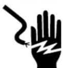
Electrical Shock Hazard
Plug into a grounded 3 prong outlet.
Do not remove ground prong.
Do not use an adapter.
Do not use an extension cord.
Failure to follow these instructions can result in death, fire, or electrical shock.
Observe all governing codes and ordinances.
Required:
■ A 120 V, 60 Hz, AC only, 15 A or 20 A electrical supply fuse or circuit breaker.
Recommended:
■ A time-delay fuse or time-delay circuit breaker.
■ A separate circuit serving only this microwave oven.
GROUNDING INSTRUCTIONS
For a grounded, cord-connected appliance:
This appliance must be grounded. In the event of a malfunction or breakdown, grounding will reduce the risk of electric shock by providing a path of least resistance for electric current. This appliance is equipped with a cord having an equipment-grounding conductor and a grounding plug. The plug must be plugged into an appropriate outlet that is properly installed and grounded in accordance with all local codes and ordinances.
WARNING: Improper connection of the equipment-grounding conductor can result in a risk of electric shock. Check with a qualified electrician or serviceman if you are in doubt as to whether the appliance is properly grounded. Do not modify the plug provided with the appliance: if it will not fit the outlet, have a proper outlet installed by a qualified electrician.
Do not use an extension cord. If the power supply cord short, have a qualified electrician or serviceman install an outlet near the microwave oven.
SAVE THESE INSTRUCTIONS
This device complies with Industry Canada ICES-001.
INSTALLATION INSTRUCTIONS
Prepare Microwave Oven
WARNING
Excessive Weight Hazard
Use two or more people to move and install or uninstall appliance.
Failure to do so can result in back or other injury.
- To avoid possible damage to the work surface, cover the work surface.
- Remove parts supplied from the outer foam in the carton and set aside for installation use.
- Remove the literature pack from the outer foam in the carton and set aside for installation use.
- Remove shipping materials, tape and film from microwave.
- Remove any loose items inside microwave oven.
- Tape the microwave oven door closed so that the door does not swing open while the microwave oven is being handled.
with a
Install the Rails-Standard
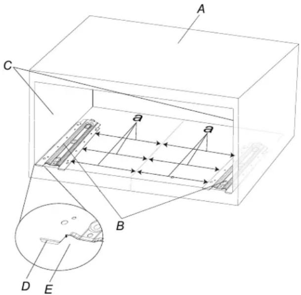
- Using measuring tape and pencil, mark the centerline of the opening on the cabinet lower front wall.
- Place the two rails inside the cabinet, make sure the stopper is against the cabinet lower edge as shown below. Measure the distance between the centerline to the rails nearest edges (a) are 10" (25.4 cm).
text_image
A C a a B D EA. Cabinet
B. Rails
C. Side wall
D. Stopper
E. Cabinet lower edge
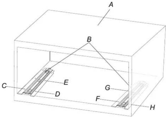
- Use a pencil to draw screw marks across six rails screw holes C, D, E, F, G, H in the cabinet. Confirm that distance between the centerline to the rails nearest edges (a) are 10" (25.4 cm). Then take out of the two rails.
text_image
A B C D E G F HA. Cabinet
B. Rails
C. Hole C on left rail
D. Hole D on left rail
E. Hole E on left rail
F. Hole F on right rail
G. Hole G on right rail
H. Hole H on right rail
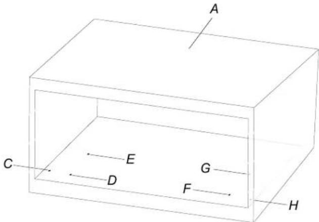
- Using a 7/64" drill bit, drill six screw pilot holes of C, D, E, F, G, H in the bottom cabinet.
text_image
A C E G D F HA. Cabinet
B. Hole C
C. Hole D
D. Hole E
E. Hole F
F. Hole G
G. Hole H
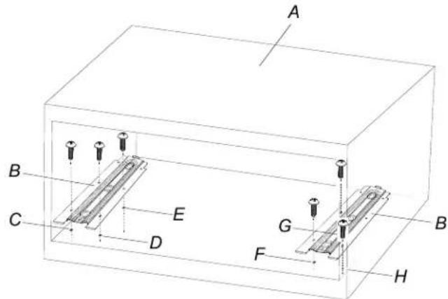
- Put the two rails inside the cabinet, and align the screw holes on rails and pilot holes on cabinet. Attach the six #7-16x7/16" round-head wood screws to fix the rails to the cabinet.
text_image
A B C E D G F H BA. Cabinet
B. Rails
C. Hole C
D. Hole D
E. Hole E
F. Hole F
G. Hole G
H. Hole H
Install the Rails-Flush
- Using measuring tape and pencil, mark the centerline of the opening on the cabinet lower front wall.
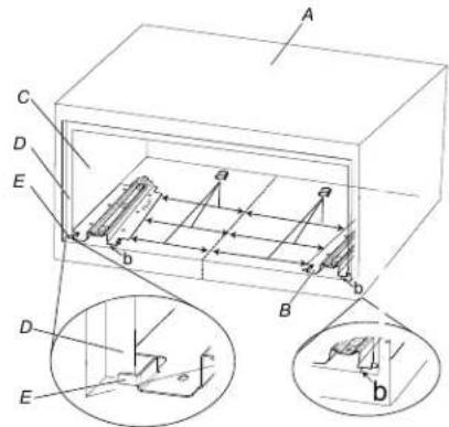
- Place the two rails inside the cabinet, make sure the stopper is against the side cleat as shown below. Measure the distance between the centerline to the rails nearest edges (a) are 9^1/4 " (23.5 cm), and the distance from the front edge of the rail to the front edge of the cabinet (b) are 1^5/16 " (3.5 cm).
text_image
Technical diagram of a mechanical assembly with labeled components and cross-sectional viewsA. Cabinet
B. Rails
C. Side wall
D. Side cleat
E. Stopper
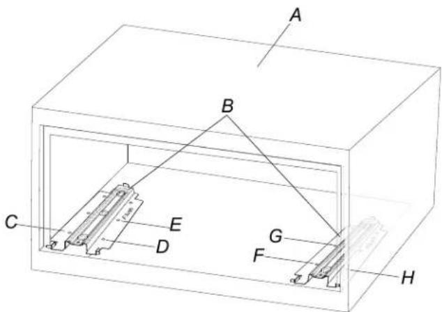
- Use a pencil to draw screw marks across six rails screw holes. Put the two rails inside the cabinet, and align the screw holes C, D, E, F, G, H in the cabinet. Confirm the distance between on rails and pilot holes on cabinet. Attach the six #7-16x7/16" the centerline to the rails nearest edges(a) and (23.5 cm). round-head wood screws to fix the rails to the cabinet. Then take out of the two rails.
text_image
A B C D E G F HA. Cabinet
B. Rails
C. Hole C on left rail
D. Hole D on left rail
E. Hole E on left rail
F. Hole F onright rail
G. Hole G on right rail
H. Hole H on right rail
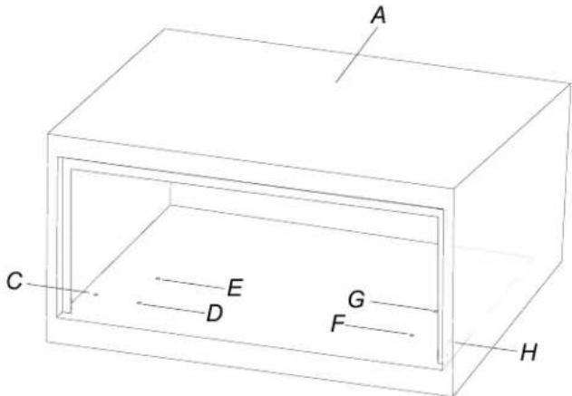
- Using a 7/64" drill bit, drill six screw pilot holes of C, D, E, F, G, H in the bottom cabinet.
text_image
A C E D G F HA. Cabinet
B. Hole C
C. Hole D
D. Hole E
E. Hole F
F. Hole G
G. Hole H
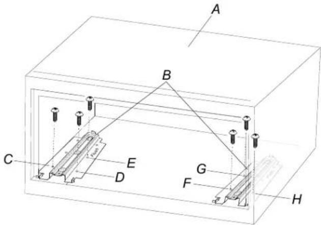
text_image
A B C D E F G HA. Cabinet
B. Rails
C. Hole C
D. Hole D
E. Hole E
F. Hole F
G. Hole G
H. Hole H
Install the brackets (for flush installation only)
For some models whose factory default setting is flush, need to install two brackets on the upper cleat of the cabinet before install the microwave oven. Follow the steps below. Skip this section for those factory default setting is standard installation.
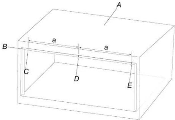
- Use measuring tape and pencil to draw a centerline on the upper cleat of the cabinet, and draw a bracket L edge line, and a bracket R edge line. Make the distance "a" between centerline to bracket edge line "a" are 116 (34.1 cm).
text_image
A a a B C D EA. Cabinet
B. Upper cleat
C. Bracket L edge line
D. Centerline
E. Bracket R edge line
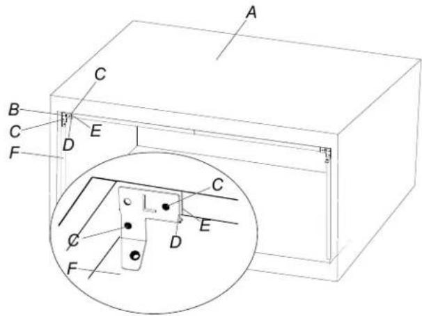
- Attach the bracket L to the upper left corner of the cleat, make sure the bracket L edge is aligned with the bracket L edge line on the cleat. Use a pencil to draw screw marks across two screw holes in the cleat.
text_image
A C B C D E F C E D FA. Cabinet
B. Bracket L
C. Screwholes
D. BracketL edge
E. Bracket L edge line
F. Cleat
-
Attach the bracket R to the upper right corner of the cleat, follow the instructions in step 2.
-
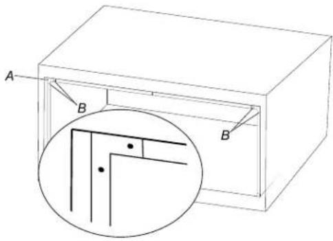
Use a 7/64" drill bit, drill four screw pilot holes (B) in the cleat.
natural_image
Technical line drawing of a rectangular enclosure with labeled corners A and B, showing internal structure and a magnified inset (no text or symbols)A. Cleat
B. Pilot hole
- Attach the bracket L to the upper left corner of the cleat, make sure the bracket L edge is aligned with the bracket L edge line on the cleat, and the screw holes align with the pilot holes in the cleat. Attach two #7-16x7/16" round-head wood screw.
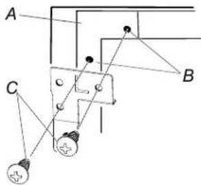
text_image
A B CA Cleat
B. Pilot hole
C. #7-16x7/16" round-head wood screw
-
Attach the bracket R to the upper right corner of the cleat, follow the instructions in step 5.
-
Use a measuring tape to confirm the "a" distances _e "13 (34.1 cm), and "b" distance are/8(45.4 cm), you may adjust brackets little bit by loosing the screws to meet the "a" and "b" distance dimensions if necessary.
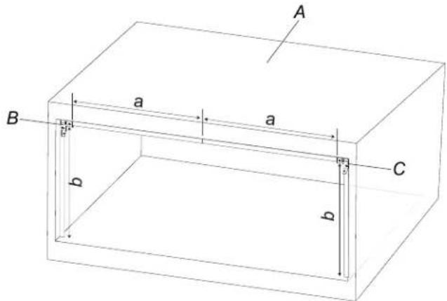
text_image
A a a B C b bA. Cabinet
B. BracketL
C. BracketR
Install the Microwave Oven
WARNING
Excessive Weight Hazard
Use two or more people to move and install or uninstall appliance.
Failure to do so can result in back or other injury.
- Position microwave oven near cutout opening.
- Plug in microwave oven.
WARNING
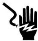
Electrical Shock Hazard
Plug into a grounded 3 prong outlet.
Do not remove ground prong.
Do not use an adapter.
Do not use an extension cord.
Failure to follow these instructions can result in death, fire, or electrical shock.
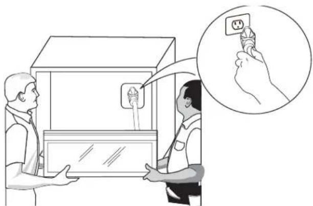
natural_image
Illustration of two people using a power station with a magnified inset showing hand holding a socket (no text or symbols)- Slide the microwave oven back and into place.
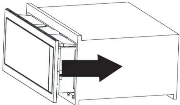
natural_image
Line drawing of a microwave oven with an arrow indicating direction (no text or symbols)- Adjust the microwave oven gently to the cutout/cabinet center.
Fasten the Microwave Oven-Standard
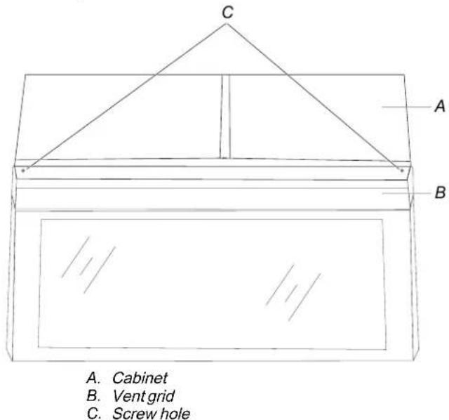
- Use 7/64" drill to drill two pilot holes into the front face of the cutout/cabinet through the mounting hole guides in the top of the vent grid.
text_image
A. Cabinet B. Vent grid C. Screw holeNOTE: The holes will be drilled downward from the top, and upward from the bottom at an angle of about 45^ .
text_image
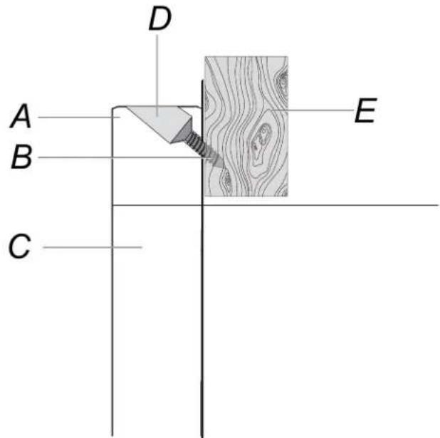
A B C D EA. Ventgrid
B. #7-16x15/16" flat head wood screw (2)
C. Microwave door
D. Mounting hole guide
E. Cutout ceiling
- Secure vent grid to cutout/cabinet installing two #7-16 x 15/16" flat head wood screws into the pilot holes drilled by hand.
NOTE: To avoid damage to the vent grid, do not overtighten screws.
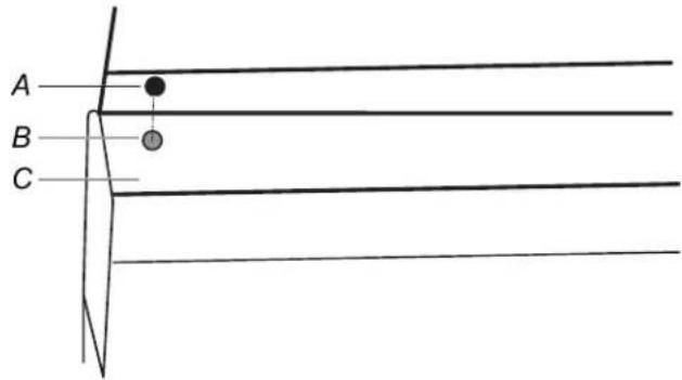
- Cover the screw hole with the two covers.
text_image
A B CFasten the Microwave Oven-Flush
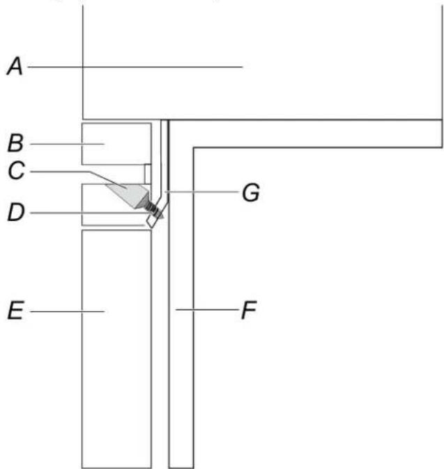
- Secure vent grid to bracket by installing two M4x1/2" flat head self-tapping screw into the pilot holes.
text_image
A B C D G E FA. Cabine
B. Ventgrid
C. Mounting hole guide
D. M4x1/2" flat head self-tapping screw(2)
E. Microwave oven door
F. Cleatof cabinet
G. Bracket
NOTE: To avoid damage to the vent grid, do not overtighten screws.
Complete Installation
-
Check the operation of microwave oven by placing 1 cup (250 ml) of water on the bottom of the cavity and programming a cook time of 1 minute at 100% power.
-
If the microwave oven does not operate:
■ Check that a household fuse has not blown, or that a circuit breaker has not tripped. Replace the fuse or reset the circuit breaker. If the problem continues, call an electrician.
■ Check that the power supply cord is plugged into a grounded 3 prong outlet.
- See the quick start guide for more informations.
The installation is now complete.
Save this owner manual for future use.
natural_image
Pure architectural line drawing of a cabinet or wardrobe unit with no text, numbers, or symbolsSÉCURITÉ DU FOUR À MICRO-ONDES
text_image
F B H E A D G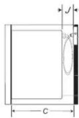
Receptacle
Back of the Cabinet
Back of the microwave oven
text_image
A C a a B D Etext_image
A B C D E G F Htext_image
A C E D G F HA. Armoire
B. Trou C
C. Trou D
D. Trou E
E. Trou F
F. Trou G
G. Trou H
text_image
A B C D E G F Htext_image
A C E D G F HA. Armoire
B. Trou C
C. Trou D
D. Trou E
E. Trou F
F. Trou G
G. Trou H
text_image
A B C D E F G HA. Armoire
B. Glissières
C. Trou C
D. Trou D
E. Trou E
F. Trou F
G. Trou G
H. Trou H
text_image
A a a B C D Etext_image
Technical diagram of a rectangular enclosure with labeled components and an inset view showing a mechanical bracket assembly.natural_image
Technical line drawing of a cabinet or enclosure with labeled components A and B, showing internal structure and a magnified inset (no text or symbols)A. Tasseau
B. Trou