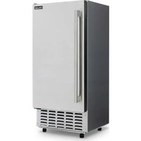
NCI066SSN0 - Ice Maker NewAir - Free user manual and instructions
Find the device manual for free NCI066SSN0 NewAir in PDF.


| Product Type | Freestanding or built-in ice maker |
| Brand | NewAir |
| Model | NCI066SSN0 |
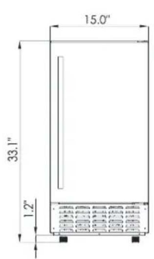
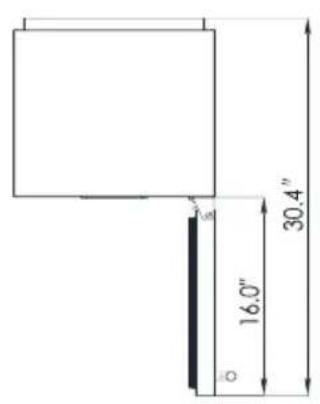
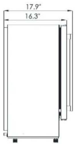
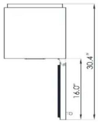
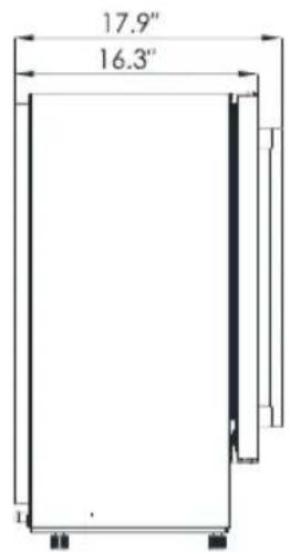
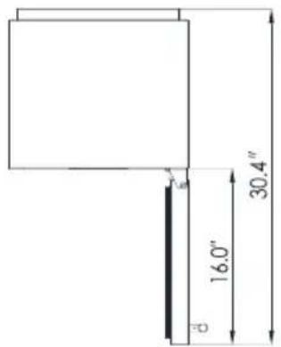
| Dimensions (W x D x H) | 15 x 17.9 (with handle) x 33.1 in |
| Weight | Not specified in manual, estimated ~55 lb (25 kg) |
| Power supply | 110-120 V, 60 Hz, 3.1 A |
| Ice production capacity | 66 lb per day (max) |
| Ice storage capacity | 17 lb |
| Refrigerant | R290 (1.34 oz / 38 g) |
| Allowable ambient temperature | 50 °F to 109 °F (10 °C to 43 °C) |
| Supply water temperature | 41 °F to 77 °F (5 °C to 25 °C) |
| Required water pressure | 0.04 to 0.6 MPa |
| Electrical connection | Grounded wall outlet, dedicated circuit recommended |
| Water connection | White supply hose (3 m) included, quick connector (1/4" to 1/2") included |
| Drainage | Gray drain hose (2 m) included |
| Main functions | Ice making, timer, self-cleaning, ambient temperature display, full ice and water shortage detection |
| Cleaning and maintenance | Interior cleaning with diluted bleach; self-cleaning cycle; exterior cleaning with mild detergent |
| Safety | Grounding required, flammable refrigerant R290, automatic shutdown in case of error, child lock not specified |
| Spare parts and repairability | One-year limited warranty; contact NewAir customer service; repairs by authorized technician |
| General information | Household and similar use (offices, hotels, kitchens), do not use outdoors |
Frequently Asked Questions - NCI066SSN0 NewAir
User questions about NCI066SSN0 NewAir
0 question about this device. Answer the ones you know or ask your own.
Ask a new question about this device
Download the instructions for your Ice Maker in PDF format for free! Find your manual NCI066SSN0 - NewAir and take your electronic device back in hand. On this page are published all the documents necessary for the use of your device. NCI066SSN0 by NewAir.
USER MANUAL NCI066SSN0 NewAir
natural_image
Line drawing of a modern stainless steel refrigerator with ventilation grilles and side-mounted door (no text or symbols)OWNER'S MANUAL
English Manual....30
A Name You Can Trust
Trust should be earned and we will earn yours. Customer happiness is the focus of our business.
From the factory to the warehouse, from the sales floor to your home, the whole Newair family promises to provide you with innovative products, exceptional service, and support when you need it the most.
Count on Newair
As a proud Newair owner, welcome to our family. There are no robots here, real people shipped your product and real people are here to help you.
Contact Us
Please reach out to our customer service team before making a return to your store of purchase. We are happy to help with any questions or concerns!
Mon-Fri from 8-4 PST at:
Call: 1-855-963-9247
Email: support@newair.com
Online: www.newair.com
A team member will respond to you within 24 hours.
Follow Us

Facebook.com/newairusa

Instagram.com/newairusa

YouTube.com/newairusa

Twitter.com/newairusa
READ AND SAVE THESE INSTRUCTIONS
TABLE OF CONTENTS
LANGUAGE INDEX 2
Table Of Contents 4
Specifications 5
Register Your Product Online....6
Safety Information & Warnings 7
Parts List....10
Main Unit Construction and Accessories 10
Circuit Diagram 11
Installation 12
Unpacking Your Ice Maker 12
Installing The Stainless Steel Door Handle....13
Installation Location Requirements 13
Installing Your Ice Maker 14
Electrical Connection 15
Water Connection for Your Ice Maker 16
Operating Instructions 18
Operation Button and Display Area Diagram 18
Display Symbol Descriptions 19
Normal Sounds....21
Cleaning & Maintenance....22
Cleaning Your Ice Maker Before First Use.... 22
Exterior Cleaning 22
Interior Cleaning 23
Steps for Cleaning the Ice-Making Parts 24
Cleaning Suggestion 25
Storage 26
Preparing the Ice Maker for Long Storage 26
Correct Disposal of This Product 26
Troubleshooting....27
Limited Manufacturer's Warranty 29
SPECIFICATIONS
| MODEL NO. | NCI066SSNO |
| VOLTAGE: | 110-120V |
| CURRENT: | 3.1A |
| FREQUENCY: | 60Hz |
| MAX. ICE MAKING CAPACITY: | 66 lbs. |
| ICE STORAGE CAPACITY: | 17 lbs. |
| AMBIENT TEMPERATURE: | 50°F - 109°F |
| REFRIGERANT: | R290 (1.34Oz / 38g) |
| PRODUCT DIMENSIONS: | 15.00” W x 17.9” D (w/handle) x 33.1” |

REGISTER YOUR PRODUCT ONLINE
Register Your Newair Product Online Today!
Take advantage of all the benefits product registration has to offer:

Service and Support
Diagnose troubleshooting and service issues faster and more accurately

Recall Notifications
Stay up to date for safety, system updates and recall notifications

Special Promotions
Opt-in for Newair promotions and offers
Registering your product information online is safe & secure and takes less than 2 minutes to complete:
newair.com/register
Alternatively, we recommend you attach a copy of your sales receipt below and record the following information, located on the manufacturer's nameplate on the rear of the unit. You will need this information if it becomes necessary to contact the manufacturer for service inquiries.
Date of Purchase: ____
Serial Number: ____
Model Number: ____
SAFETY INFORMATION & WARNINGS

Your safety and the safety of others are very important to us.
We have provided many important safety messages in this manual and on your appliance. Always read and obey all safety messages.
This is the Safety Alert Symbol. The symbol alerts you to potential hazards that can kill or injure you and others. All safety messages will follow the Safety Alert Symbol and the words “DANGER” or “WARNING”.
DANGER: Danger means that failure to heed this safety statement may result in severe injury or death.
WARNING: Warning means that failure to heed this safety statement may result in extensive product damage, serious injury, or death.
All safety messages will alert you to know what the potential hazard is, tell you how to reduce the chance of injury, and let you know what can happen if the instructions are not followed.

DANGER
IMPORTANT SAFETY GUIDELINES
Before the appliance is used, it must be properly positioned and installed as described in this manual. Please read the manual carefully. To reduce the risk of fire, electrical shock, or injury when using the appliance, follow basic safety precautions, including the following:
- Always plug appliance directly into a grounded 3-prong outlet. Do not remove grounding prong. Do not use an adapter or extension cord.
- It is recommended that a separate circuit serving only your appliance be used. Do not use outlets that can be turned off by a switch or pull chain.
- Never clean appliance parts with flammable fluids. These fumes can create a fire hazard or explosion.
- Do not store or use gasoline or other flammable vapors and liquids in the vicinity of this or any other appliance. The fumes can create a fire hazard or explosion.
- Do not connect or disconnect the power cord with wet hands.
- Unplug the appliance or disconnect power before cleaning or servicing. Failure to do so can result in electrical shock or death.
- Do not attempt to repair or replace any part of your appliance unless it is specifically recommended in this manual. For any further issues, please contact customer service at support@newair.com.

WARNING
- Use two or more people to move and install the appliance. Failure to do so can result in injury.
- To ensure proper ventilation for your appliance, the front of the unit must be completely unobstructed.
- Install the appliance in a well-ventilated area with temperatures above 50irc F ( 10irc C) and below 109irc F ( 43irc C).
- The appliance should not be located next to ovens, grills, or other sources of high heat.
- The appliance must be installed with all electrical, water, and drain connections (if applicable) in accordance with state and local codes.
- Do not kink or pinch the power cord.
- The appliance must be leveled in order to work properly. You may need to make adjustments to the feet to achieve a level surface.
- All installations must be in accordance with local plumbing code requirements (if applicable).
- Ensure that the pipes are not pinched, kinked, or damaged during installation.
- Check for leaks of any kind after turning on the appliance for the first time.
- Do not use solvent-based cleaning agents or abrasives on the appliance as they can damage or discolor the unit.
- Use this appliance only for its intended purpose as described in this instruction manual.
- WARNING: Keep ventilation openings, in the appliance enclosure or in the built-in structure, clear of obstruction.
- WARNING: Do not damage the refrigerant circuit.
- WARNING: This appliance is not intended for use by persons (including children) with reduced physical, sensory or mental capabilities, or lack of experience and knowledge, unless they have been given supervision or instruction concerning use of the appliance by a person responsible for their safety.

- WARNING: Children should be supervised to ensure that they do not play with the appliance.
- WARNING: This appliance must be earthed. And use the 110-120V/60Hz earthed power supply.
- DANGER – Risk Of Fire or Explosion. Flammable Refrigerant Used. Do Not Use Mechanical Devices To Defrost Ice Maker. Do Not Puncture Refrigerant Tubing.
- CAUTION – Risk Of Fire Or Explosion. Flammable Refrigerant Used. Consult Repair Manual/Owner's Guide Before Attempting To Install or Service This Product. All Safety Precautions Must be Followed.
- CAUTION – Risk Of Fire Or Explosion. Dispose Of Property In Accordance With Federal Or Local Regulations. Flammable Refrigerant Used.
- CAUTION – Risk Of Fire Or Explosion Due To Puncture Of Refrigerant Tubing; Follow Handling Instructions Carefully. Flammable Refrigerant Used.
- The ice maker should be installed in accordance with the safety standard for Refrigeration Systems, ASHRAE15. The ice maker shall not be installed in corridors or hallways of public buildings.
- WARNING: Keep ventilation openings, in the appliance enclosure or in the built-in structure, clear of obstruction.
- WARNING: This appliance is intended to be used in household and similar applications such as
E.g.staff kitchen areas in shops, offices and other working environments;
E.g. farm houses and by clients in hotels, motels and other residential type environments;
E.g.bed and breakfast type environments;
E.g. catering and similar non-retail applications.
- To avoid a hazard due to instability of the appliance, it must be placed at a even or flat surface.
- Keep fingers out of "pinch point" areas. Clearances between the door and cabinet are small. Be careful closing the door when children are nearby.
- Never allow children to operate, play with, or crawl inside the appliance.
Attention: Child Entrapment Risk!
Junked or abandoned appliances are dangerous to children, regardless of how long they are left to sit. Before discarding your unit, remove the doors and leave the shelves in place so that children may not easily climb inside.
- SAVE THESE INSTRUCTIONS -
PARTS LIST
MAIN UNIT CONSTRUCTION AND ACCESSORIES
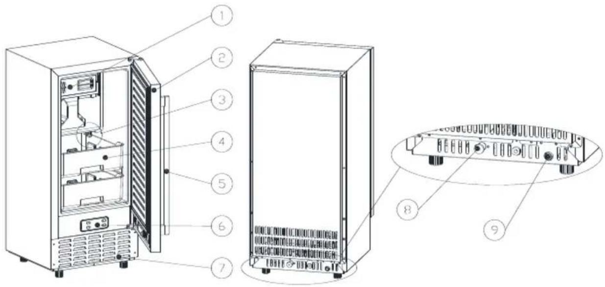
- Transparent waterproof cover
- Door
- Drainage plug
- Ice tank
- Handle
- Operation panel
- Air outlet (keeps air circulating smoothly; hot air will blow out when unit is running)
- Water draining port (plugged with cap in resting state; unplug to drain water when needed and connect white drainpipe)
- Water inlet port for water supply (use to connect the water supply pipe)
Accessories:
- 6.56 ft (2 m) long water drainpipe
- 9.84 ft (3 m) long white water supply tube. Φ 0.25 in (6.35 mm)
- White quick connector (1/4" to 1/2")
- Ice shovel
CIRCUIT DIAGRAM
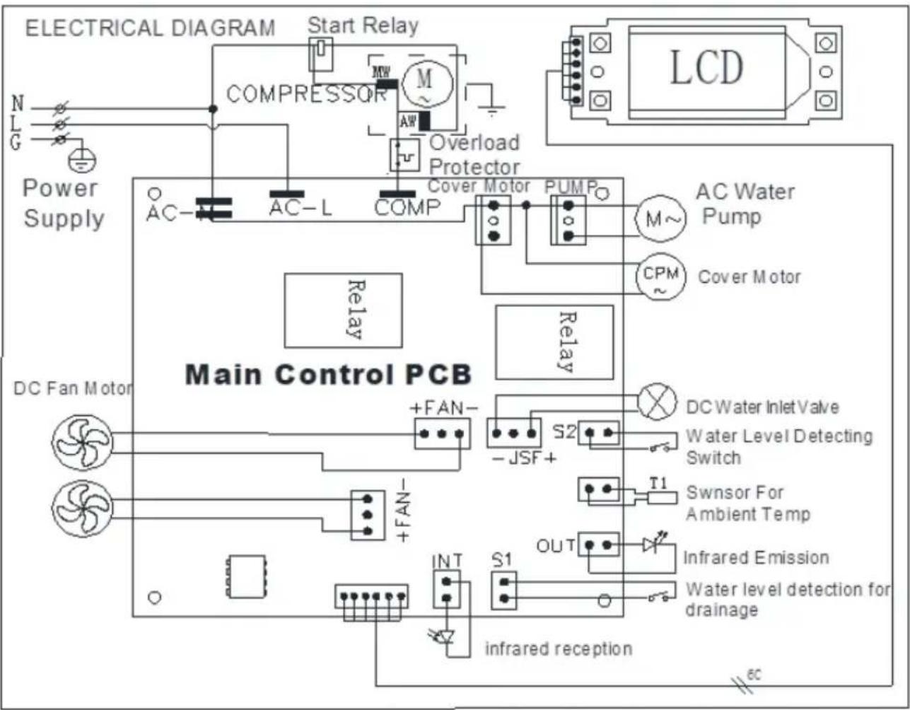
flowchart
graph TD
    A["Main Control PCB"] --> B["Start Relay"]
    B --> C["COMPRESSOR"]
    C --> D["M~"]
    D --> E["Overload Protector"]
    E --> F["AC-L"]
    F --> G["AC-"]
    G --> H["Power Supply"]
    H --> I["DC Fan Motor"]
    I --> J["+FAN-"]
    J --> K["S2"]
    K --> L["-JSF+"]
    L --> M["T1"]
    M --> N["Swnor For Ambient Temp"]
    N --> O["Infrared Emission"]
    O --> P["OUT"]
    P --> Q["Water level detection for drainage"]
    Q --> R["infrared reception"]
    R --> S["Relay"]
    S --> T["Cover Motor"]
    T --> U["PUMP"]
    U --> V["AC Water Pump"]
    V --> W["Cover Motor"]
    W --> X["LCD"]
INSTALLATION
UNPACKING YOUR ICE MAKER
- Remove the exterior and interior packaging. Check that all accessories are inside. If any parts are missing, please contact customer service.
- Remove stabilizing tape from door and inner cabinet, ice scoop, etc. Clean the inner cabinet and ice scoop with wet cloth.
- Place the ice maker on a flat and level area of the floor away from direct sunlight and other sources of heat (stove, furnace, radiator, etc.). Ensure that there is at least a 2 ft. gap between the unit's air outlet and any obstructions, and at least 2 inches between the unit and the wall.
- Before plugging in the icemaker, let it stand upright for approximately 4 hours. Doing this will reduce the possibility of a malfunction in the cooling system from handling during transportation.
- The appliance must be positioned so that the plug is accessible.
- Clean the interior surface with lukewarm water using a soft cloth.
- Install the door handle (see detailed instructions on the following page).
WARNING: connect unit to a potable water supply only. Only use drinking water to supply your ice maker.
INSTALLING THE STAINLESS STEEL DOOR HANDLE
To install the door handle, follow the instructions below:
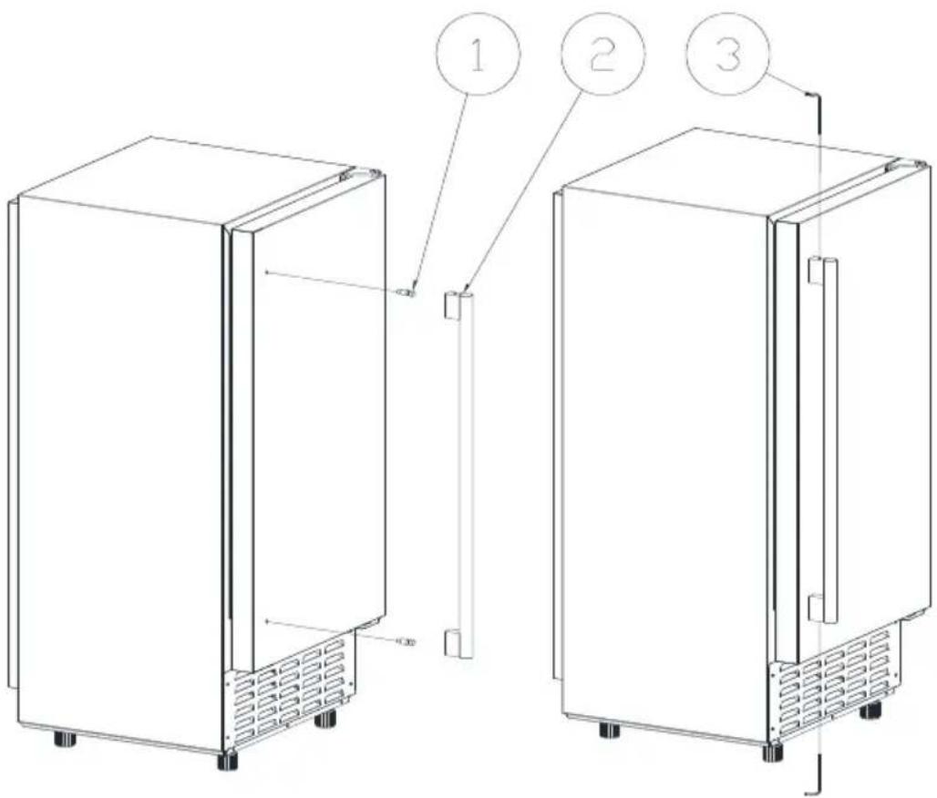
- Locate the two set screws and fix it into the pilot holes shown in (1).
- Find the door handle (2) and align the holes to the set screws.
- Use the included hex wrench to fix the handle screws (3) to the set screws.
INSTALLATION LOCATION REQUIREMENTS
- This unit is not for outdoor use. Maintain the proper room and inlet water temperatures according to above specification tables to ensure proper ice making performance.
• This unit should not be located near any significant source of heat. - The unit should be located on a firm and level foundation at normal countertop height.
-
There must be at least 2-inch clearance at the rear of the unit for connection to the power supply and 10 inches clearance in front to allow for the door to open and to maintain adequate air circulation.
-
Do not place or store anything on top of the ice maker.
- To ensure proper ventilation for your ice maker, the front of the unit must be completely unobstructed (at least 10 inches of free space). Allow about 2 inches clearance at rear, and 2 inches at the top for proper air circulation. The installation and placement should allow the ice maker to be pulled forward for servicing if necessary.
- Choose a well-ventilated area with temperatures above 50irc F and below 90irc F.
This unit must be installed in an area protected from elements, such as wind, rain, water spray, or drips. The ice maker requires a continuous water supply. The temperature of the water supplying the ice maker should be between 41irc F and 77irc F for proper operation.
INSTALLING YOUR ICE MAKER
This ice maker is designed to be either built-in or freestanding.
Place your ice maker on a floor that is strong enough to support it when it is fully loaded. To level the unit, adjust the front leveling legs.

WARNING: Ensure that the air vent at the front of the appliance is never covered or blocked in any way.
Note: It is recommended that you do not install the appliance near an oven, radiator, or other heating source. Any nearby heat sources may increase electrical consumption. Do not install in a location where the temperature will fall below 50irc F ( 10irc C) or above 109irc F ( 43irc C). For best performance, do not install the ice maker behind a cabinet door or block the front vent.
Avoid installing the ice maker anywhere with excessive moisture.
Plug the ice maker into a properly grounded wall outlet. Do not plug the ice maker into a power strip or extension cord. If you must use an extension cord, it is absolutely necessary that it be a UL/CUL-listed, 3-wire grounding extension cord with a grounding plug and outlet. The electrical rating of the cord should be 110 volts.
ELECTRICAL CONNECTION

WARNING: THIS UNIT MUST BE EARTHED
Electrical Shock Hazard: plug into a grounding wall outlet.
- Never remove the ground prong.
- Use separate power supply or receptacle. Never use an adapter.
- Never use an extension cord.
- Failure to follow these instructions can result in death, fire, or electrical shock.
Before you move your ice maker into its final location, it is important to make sure you have the proper electrical connection nearby.
It is recommended to connect to a separate circuit solely for the ice maker. Use receptacles that cannot be turned off by a switch or pull chain.
This appliance requires a standard 110-120Volt, 60Hz electrical outlet with grounding.
Recommended grounding method
To minimize possible shock hazard, the cord must be plugged into a mating grounding-type wall receptacle, grounded in accordance with the National Electrical Code and local codes and ordinances. If a mating wall receptacle is not available, it is the personal responsibility of the customer to have a properly grounding wall receptacle installed by a qualified electrician.
If you have any of these issues, contact customer service immediately at support@newair.com.
When moving the appliance, be careful not to damage the power cord.
WATER CONNECTION FOR YOUR ICE MAKER
Important: Be sure to use the new hose sets supplied with the appliance to connect to water mains. Old hose sets should not be reused.
1. Connect the water supply hose to the unit
First, remove the tape on the water inlet port (indicated in the following illustration as "B") located at the back of the unit, then use your finger to press and remove the plastic circular cover ("A"). Next, insert one end of the white water hose into the water inlet port and push inward completely. Follow step #2 in the diagram. Water hose connection is now complete.
2. Connect the water drainpipe
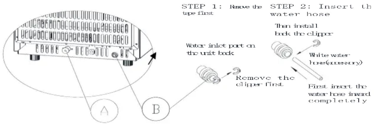
Remove the black water drainage cap (indicated as "A" in above illustration), then connect the gray drainage pipe. Connect the other end of the drainpipe to the main water drainage pipe in your house. Note: the white washer included in the packaging fits between the water inlet port and the white-water tube.
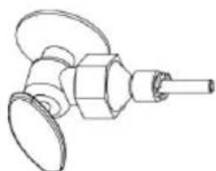
3. Connect the water hose to the faucet of the main water supply system
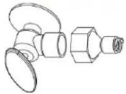
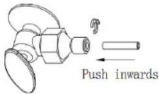
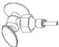
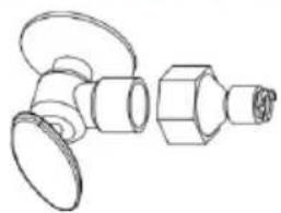
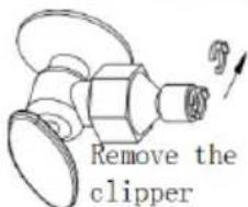
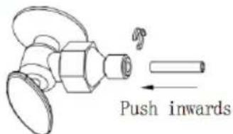
First, install the supplied water quick-connector to the water faucet by screw thread. Second, remove the clipper from the water quick-connector, insert the other end of the water hose into this quick-connector port completely, then re-install the clipper. The water hose is now connected to the water supply. Note: The water faucet is supplied by the unit owner and is not included in the unit assembly.
Important: The water pressure of the main water supply system must be at least 0.04-0.6 MPa.
STEP 1: Quick-connector and the water faucet
STEP 2: Screw the quick-connector on the water faucet by the screw thread, and remove the clipper
STEP 4: Install back the clipper
natural_image
Technical line drawing of a mechanical valve assembly (no text or symbols)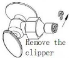
natural_image
Line drawing of a mechanical component with a cylindrical shaft and flanged end (no text or symbols)STEP 3: Insert the water hose completely
OPERATING INSTRUCTIONS
OPERATION BUTTON AND DISPLAY AREA DIAGRAM
OPERATION AREA

DISPLAY AREA
OPERATION AREA
| (TIMER) CLEAN | ⇒ Press once to activate timer setting mode⇒ Press & hold for more than 5 seconds to enter cleaning mode |
| (ON/OFF) | ⇒ When unit is off, press once to power on the unit⇒ When unit is on either making ice or in cleaning mode, press once to power off the function⇒ When unit is in timer setting mode, press once to exit timer setting |
| LCD display window | Function display panelMore details of symbols shown below. |
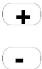
| (+) (-) | Timer adjustment |
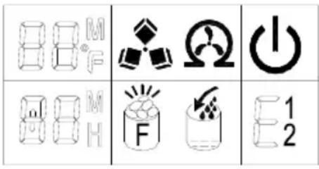
DISPLAY SYMBOL DESCRIPTIONS
| 1 | Ambient temperature displayPress “+”button longer than 5s to switch between Fahrenheit (°F) or Celsius (°C). | 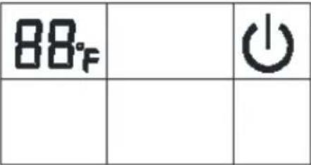 |
| 2 | Ice Making symbol⇒ The machine is making ice when this symbol has a rotating animation⇒ The symbol will flash when there is an error during ice making process | 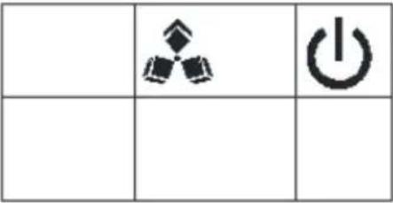 |
| 3 | Automatic self-cleaning symbol display.⇒ The unit will use the inlet water to rinse through all the water channels⇒ The default cleaning time is 15 minutes.⇒ Press the “(ON/OFF)” to force cancel the self-cleaning mode. | 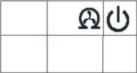 |
| 4 | On/off symbol |  |
| 5 | Error code display⇒ E1 No water ingress for a long time⇒ E2 means the ambient temperature sensor is damaged.⇒ E means drain pump is not working. | 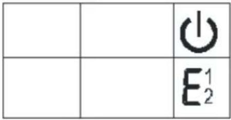 |
| 6 | Water flow in and water shortage display⇒ The arrow flashing indicates that the machine is adding water.⇒ The symbol stays On to indicate water shortage | 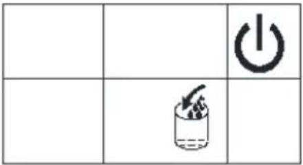 |
| 7 | Ice full alarm⇒ The machine will start ice making process again when you remove the ice.⇒ If this symbol does not disappear even when removing the ice, long press the power button to force ice production for 80 minutes | 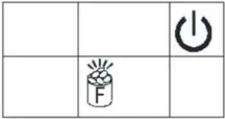 |
| 8 | Timer countdown to start/end⇒ When the machine is in ice making mode, press (TIMER) CLEAN to set a timer to end ice production. Use “+” and “-” to adjust the interval.⇒ When the machine is on standby, press (TIMER) CLEAN to set a timer to begin ice production. Use “+” and “-” to adjust the interval. | 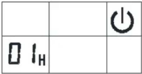 |
NORMAL SOUNDS
Your new ice maker may make sounds that are not familiar to you. Most of these sounds are normal. Hard surfaces like the floor, walls, and cabinets can make the sounds seem louder than they are. The following list describes the types of sounds you might hear from your unit and what might be causing them:
- You will hear a swooshing sound when the water valve opens to fill the water tank for each cycle.
- Rattling noises may come from the flow of the refrigerant or the water line. Items stored on top of the ice maker can also make noises. (Do not store items on top of the unit.)
- The high-efficiency compressor may make a pulsating or high-pitched sound.
- Water running from the water tank to the evaporator plate may make a splashing sound.
- Water running from the evaporator to the water tank may make a splashing sound.
- As each cycle ends, you may hear a gurgling sound due to the refrigerant flowing in your icemaker.
- You may hear air being forced over the condenser by the condenser fan. During the harvest cycle, you may hear the sound of ice cubes falling into the ice storage bin.
- When you first start the ice maker, you may hear water running continuously. The ice maker is programmed to run a rinse cycle before it begins to make ice.
CLEANING YOUR ICE MAKER BEFORE FIRST USE
Before using your ice maker, cleaning it thoroughly is strongly recommended
WARNING: Before carrying out any cleaning or maintenance operations, unplug the ice maker from the main power supply. (EXCEPTION: Ice maker self-cleaning program.)
- Do not use any alcohol or fumes for cleaning or sanitizing the ice maker. This may cause cracking on the unit's plastic features.
- To ensure proper functioning of your unit, ask a trained service person to check and clean the condenser at least once a year.
- This appliance must be cleaned by use of a water jet.
CAUTION: If the ice maker has been left unused for a long time, it must be thoroughly cleaned before the next use. Carefully follow any instructions provided for cleaning or using sanitizing solution. Do not leave any solution inside the ice maker after cleaning.
Periodic cleaning and proper maintenance will ensure efficiency, top performance, hygiene, and long life for your appliance. The maintenance intervals listed are based on normal conditions. You may want to shorten the intervals if you have pets, or if there are other special considerations.
What NOT to do
Never keep anything in the ice storage bin that is not ice. Objects like wine and beer bottles are not only unsanitary, but their labels may slip off and obstruct the drainpipe.
EXTERIOR CLEANING
The door and cabinet may be cleaned with a mild detergent and warm water solution, such as 28g of dish washing liquid mixed with 7.5L of warm water. Do not use solvent-based or abrasive cleaners. Use a soft sponge, and rinse with clean water. Wipe dry with a soft, clean towel to prevent water spotting.
Note: stainless-steel models can discolor when exposed to chlorine. Clean stainless-steel models with a mild detergent and warm water solution and a damp cloth. Never use abrasive cleaning agents.
NOTICE: Stainless steel models exposed to chlorine gas and moisture, such as in areas with spas or swimming pools, may show some discoloration. Discoloration from chlorine gas is normal.
INTERIOR CLEANING
For Ice Storage Bin
The ice storage bin should be sanitized occasionally. Clean the bin before the ice maker is used for the first time and reused after an extended period without use. It is usually convenient to sanitize the bin after the ice-making system has been cleaned, and the storage bin is empty.
- Disconnect power to the unit.
- Open the door and, with a clean cloth, wipe down the interior with a sanitizing solution made of 28g of household bleach or chlorine and 7.5L of hot water (95°F to 115°F).
- Rinse thoroughly with clean water. The wastewater will be drained out through the drainpipe.
- Reconnect power to the unit.
The ice scoop should be washed regularly. Wash it just like any other food container.
WARNING: DO NOT use solvent cleaning agents or abrasives on the interior. These cleaners may transmit taste to the ice cubes or damage or discolor the interior.
STEPS FOR CLEANING THE ICE-MAKING PARTS
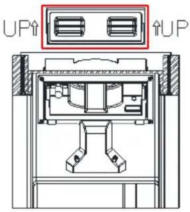
Fig. 1
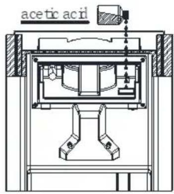
Fig. 2

natural_image
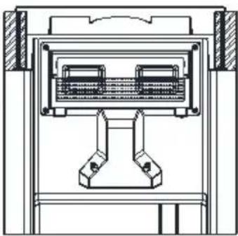
Technical line drawing of a mechanical assembly with two components and housing (no text or symbols)Fig. 3
To clean:
- Be sure your icemaker is connected to a water supply.
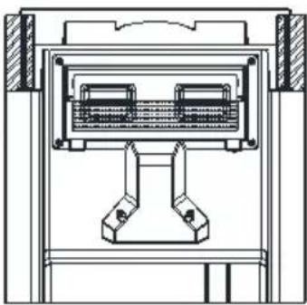
- Open the door of the unit and use both thumbs to open the transparent window and slide it upwards (Fig. 1).
- Clean the inner parts that make contact with water.
- Add appropriate amounts of acetic acid solution to the indicated position shown (Fig. 2)
- Reinstall the transparent window to prevent water leakage. (Fig. 3)
-
Press the (Timer) Clean button on the operation panel for more than 5 seconds to start the cleaning program, which will run for 15 minutes.
-
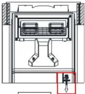
You can pull the drain plug (Fig. 4), to drain the cleaned water solution.
-
After the solution is drained, reinstall the drain plug.
-
Start another cleaning cycle again, then when it finishes, press the (ON/OFF) button to start ice production
-
Ice produced in the first 15 minutes is not recommended for consumption.
-
Dry the interior and exterior with a clean, soft cloth.
natural_image
Technical diagram of a mechanical or electrical component with internal components and a highlighted section (no text or symbols)Fig. 4
CLEANING SUGGESTION
During use, periodically clean the main system of your ice maker. Read the detailed instructions or visit this link to the Newair Support Center for more information on how to clean your ice maker:
https://newairsupport.zendesk.com/hc/en-us/articles/12294930453780-
Cleaning-Your-Ice-Maker
DAILY CLEANING
The ice shovel and door should be cleaned each day. At the end of every day, rinse the ice shovel and wipe both sides of the door with a clean cloth.
SEMI-MONTHLY CLEANING
The ice shovel, ice bin, water tank, the ice-full detecting plate, and the surface of the evaporator are to be cleaned semi-monthly according to the interior cleaning program described above.
SEMI-ANNUAL CLEANING
All components and surfaces exposed to water or ice cubes, like the ice storage bin, water tank, door, evaporator, water pump, silicone tube, water-dividing pipe, etc. should be cleaned using a Nickle Safe Ice-machine Cleaner every 6 months. They should be cleaned by a service person according to the ice-making assembly system cleaning program.
STORAGE
PREPARING THE ICE MAKER FOR LONG STORAGE
If the ice maker will not be used for a long time, or if you intend to move it to another location, you will need to drain out all the water in the system.
- Allow all existing ice cubes to be ejected from the evaporator of the ice maker.
- Turn off the unit and unplug the power cord.
- Shut off the water supply at the main water source.
- Disconnect the water supply hose from the water inlet valve.
- Remove the water drainpipe from the water tank (indicated by "H" in the above illustration) to drain the water from the water tank. When all water has been drained out, reinstall the drainpipe in the water tank.
- Drain out all water from the water drain port located at the back of the unit (indicated by "7" in the above illustration).
- Disconnect the water drainpipe from the main drain pipeline or floor drain, and reinstall the drain cap.
- Leave the unit door open to allow for air circulation and to prevent mold and mildew growth.
- Leave water supply hose and power cord disconnected until unit is ready for continued use.
- Dry the interior and wipe the outside of the unit.
- Once the unit has been dried completely, place a large plastic bag over the unit to prevent the accumulation of dust and dirt.
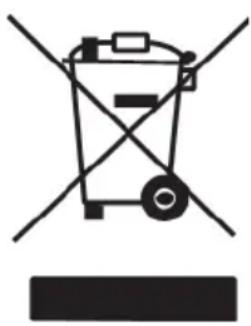
CORRECT DISPOSAL OF THIS PRODUCT
This marking indicates that this product should not be disposed of with other household wastes throughout the EU. To prevent possible harm to the environment or human health from uncontrolled waste disposal, recycle it responsibly to promote the sustainable reuse of material resources. To return your used device, please use the return and collection systems or contact the retailer where the product was purchased. They can take this product for environmentally safe recycling.
natural_image
Pure electrical circuit lines without any symbolsTROUBLESHOOTING
| Problem | Possible Cause | Solution |
 indicator light is on indicator light is on | Water shortage | Stop the ice maker, fill water, and press ON/OFF button again to restart the unit |
| Check the main water supply pressure or check whether the water supply hose is blocked. Increasing water pressure or cleaning the hose may be necessary. | ||
| If arrow is flashing | Indicates that water is filling the tank. | |
 indicator light is on and “F” flashes indicator light is on and “F” flashes | Ice tray is at full capacity | Remove the ice |
| If triggered, but ice tray is not full | Remove the probable obstacle inside or clean the inside wall of the ice storage | |
| Long press the “ON/OFF” button for 5 seconds to force ice production for 80 minutes | ||
 light flashes and no ice produced light flashes and no ice produced | Internal refrigeration system may be frozen | Shut off and unplug unit and allow at least 1 hour of standby |
| Ambient temperature is too low | Make sure the ambient temperature is above 50° and below 109°F | |
| Water temperature is too low | Make sure water is above 41° and below 77°F | |
| E1 | Ambient temperature or water temperature in inner tank is too high | Run the ice maker in ambient temperatures below 90°F and use colder water |
| Refrigerant liquid leakage | Press the “ON/OFF” button twice to restart ice production. If this is a recurring issue, verify by a qualified technician | |
| Cover motor is broken | ||
| Pipe in the cooling system is blocked | ||
| E2 | Ambient temperature sensor is damaged | Verify by a qualified technician |
| E | Drain pump is not working | Press the “ON/OFF” button to put the unit on standby then unplug and plug the ice maker again |
| Verify by a qualified technician | ||
| Making ice too slowly | Hot air outlet blockage | Make sure there are at least 6” (15cm) of space between the unit and any obstructions |
| Water temperature in inner tank is too high | Make sure water temperature is between 41-77°F | |
| Refrigeration system malfunction | Verify by a qualified technician | |
| Water leakage | Drain plug or outlet drainpipe are not in place | Securely fasten the drain plug and drainpipe into place |
| Internal component failure water leakage | Verify by a qualified technician |
LIMITED MANUFACTURER'S WARRANTY
This appliance is covered by a limited manufacturer's warranty. For one year from the original date of purchase, the manufacturer will repair or replace any parts of this appliance that prove to be defective in materials and workmanship, provided the appliance has been used under normal operating conditions as intended by the manufacturer.
Warranty Terms:
During the first year, any components of this appliance found to be defective due to materials or workmanship will be repaired or replaced, at the manufacturer's discretion, at no charge to the original purchaser. The purchaser will be responsible for any removal or transportation costs.
Warranty Exclusions:
The warranty will not apply if damage is caused by any of the following:
- Power failure
- Damage in transit
- Improper power supply such as low voltage, defective household wiring or inadequate fuses
- Accident, alteration, misuse, or abuse of the appliance such as using non-approved accessories, inadequate air circulation in the room or abnormal operating conditions (extreme temperatures)
- Use in commercial or industrial applications
- Use of force or damage caused by external influences
- Partially or completely dismantled appliances
- Excess wear and tear by the user
Obtaining Service:
When making a warranty claim, please have the original bill of purchase with the purchase date available. Once confirmed that your appliance is eligible for warranty service, all repairs will be performed by a Newair™ authorized repair facility. The purchaser will be responsible for any removal or transportation costs. Replacement parts and/or units will be new, re-manufactured or refurbished and is subject to the manufacturer's discretion. For technical support and warranty service, please email support@newairusa.com.
Un nom de confiance
Instagram.com/newairusa
Twitter.com/newairusa
LISEZ ET GARDEZ CES INSTRUCTIONS
TABLE DES MATIÈRES
Spécifications 32
ENREGISTRER VOTRE PRODUIT EN LIGNE
EXIGENCES RELATIVES AU LIEU D'INSTALLATION
STEP 1: Quick-connector and the water faucet
natural_image
Technical line drawing of a mechanical component with no visible text or symbolsSTEP 2: Screw the quick-connector on the water faucet by the screw thread, and remove the clipper
STEP 4: Install back the clipper
natural_image
Line drawing of a mechanical component with no visible text or symbolsSTEP 3: Insert the water hose completely
DIAGRAMME BOUTON DE COMMANDE ET ZONE D'AFFICHAGE
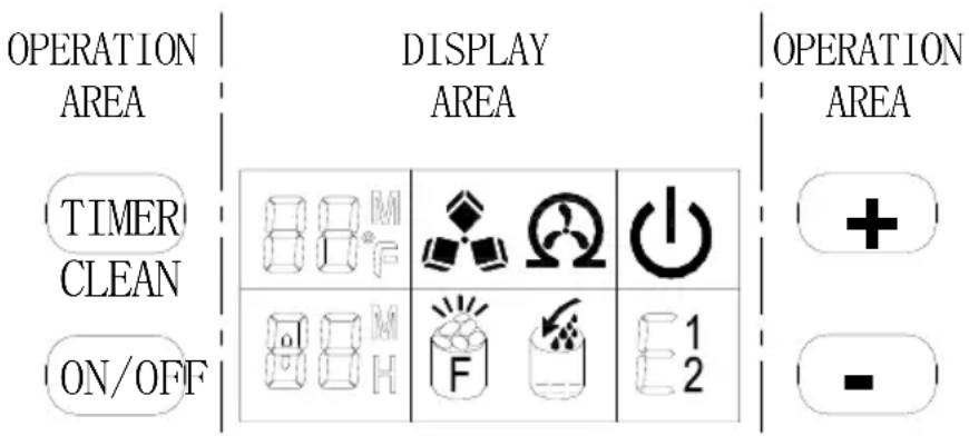
Fig. 2

natural_image
Technical line drawing of a mechanical assembly with two symmetrical components (no text or symbols)Fig. 3
Pour nettoyer:
natural_image
Technical line drawing of a mechanical assembly with two components and a highlighted section (no text or symbols)Fig. 4
SUGGESTION DE NETTOYAGE
https://newairsupport.zendesk.com/hc/en-us/articles/12294930453780-Cleaning-Your-Ice-Maker
NETTOYAGE QUOTIDIEN
ÉLIMINATION CORRECTE DE CE PRODUIT
natural_image
Symbol of a trash bin with crossed lines indicating no waste or discharge (no text or labels)DÉPANNAGE
Email: support@newair.com
Instagram.com/newairusa

YouTube.com/newairusa

Twitter.com/newairusa
LEA Y GUARDE ESTAS INSTRUCCIONES
INDICE
Especificaciones 61
REGISTRE SU PRODUCTO EN LÍNEA
flowchart
graph LR
    A["STEP 1: Quick-connector and the water faucet"] --> B["STEP 2: Screw the quick-connector on the water faucet by the screw thread, and remove the clipper"]
    B --> C["STEP 4: Install back the clipper"]
    C --> D["Push inwards"]
STEP 3: Insert the water hose completely
Fig. 2

natural_image
Technical line drawing of a mechanical assembly with two internal components (no text or symbols)Fig. 3
https://newairsupport.zendesk.com/hc/en-us/articles/12294930453780-Cleaning-Your-Ice-Maker
LIMPIEZA DIARIA
natural_image
Symbol of a trash bin crossed with diagonal lines, no text or numbers present


- OWNER'S MANUAL
- A Name You Can Trust
- Count on Newair
- Contact Us
- Follow Us
- READ AND SAVE THESE INSTRUCTIONS
- TABLE OF CONTENTS
- REGISTER YOUR PRODUCT ONLINE
- Register Your Newair Product Online Today!
- Service and Support
- Recall Notifications
- Special Promotions
- newair.com/register
- SAFETY INFORMATION & WARNINGS
- Your safety and the safety of others are very important to us.
- DANGER
- IMPORTANT SAFETY GUIDELINES
- WARNING
- Attention: Child Entrapment Risk!
- - SAVE THESE INSTRUCTIONS -
- PARTS LIST
- MAIN UNIT CONSTRUCTION AND ACCESSORIES
- Accessories:
- CIRCUIT DIAGRAM
- INSTALLATION
- UNPACKING YOUR ICE MAKER
- INSTALLING THE STAINLESS STEEL DOOR HANDLE
- INSTALLATION LOCATION REQUIREMENTS
- INSTALLING YOUR ICE MAKER
- ELECTRICAL CONNECTION
- WARNING: THIS UNIT MUST BE EARTHED
- Recommended grounding method
- WATER CONNECTION FOR YOUR ICE MAKER
- Connect the water supply hose to the unit
- Connect the water drainpipe
- Connect the water hose to the faucet of the main water supply system
- OPERATING INSTRUCTIONS
- OPERATION BUTTON AND DISPLAY AREA DIAGRAM
- DISPLAY SYMBOL DESCRIPTIONS
- NORMAL SOUNDS
- CLEANING YOUR ICE MAKER BEFORE FIRST USE
- What NOT to do
- EXTERIOR CLEANING
- INTERIOR CLEANING
- For Ice Storage Bin
- STEPS FOR CLEANING THE ICE-MAKING PARTS
- To clean:
- CLEANING SUGGESTION
- DAILY CLEANING
- SEMI-MONTHLY CLEANING
- SEMI-ANNUAL CLEANING
- STORAGE
- PREPARING THE ICE MAKER FOR LONG STORAGE
- CORRECT DISPOSAL OF THIS PRODUCT
- TROUBLESHOOTING
- LIMITED MANUFACTURER'S WARRANTY
- Warranty Terms:
- Warranty Exclusions:
- Obtaining Service:
- Un nom de confiance
- LISEZ ET GARDEZ CES INSTRUCTIONS
- TABLE DES MATIÈRES
- ENREGISTRER VOTRE PRODUIT EN LIGNE
- EXIGENCES RELATIVES AU LIEU D'INSTALLATION
- DIAGRAMME BOUTON DE COMMANDE ET ZONE D'AFFICHAGE
- Pour nettoyer:
- SUGGESTION DE NETTOYAGE
- NETTOYAGE QUOTIDIEN
- ÉLIMINATION CORRECTE DE CE PRODUIT
- DÉPANNAGE
- LEA Y GUARDE ESTAS INSTRUCCIONES
- INDICE
- REGISTRE SU PRODUCTO EN LÍNEA
- LIMPIEZA DIARIA
Brand : NewAir
Model : NCI066SSN0
Category : Ice Maker