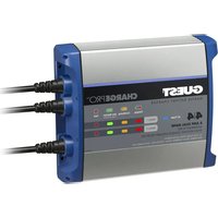
ChargePro 2707A - Battery charger Guest - Free user manual and instructions
Find the device manual for free ChargePro 2707A Guest in PDF.


User questions about ChargePro 2707A Guest
0 question about this device. Answer the ones you know or ask your own.
Ask a new question about this device
Download the instructions for your Battery charger in PDF format for free! Find your manual ChargePro 2707A - Guest and take your electronic device back in hand. On this page are published all the documents necessary for the use of your device. ChargePro 2707A by Guest.
USER MANUAL ChargePro 2707A Guest
Energy Saving Technology
Owner's Manual and Installation Guide
| Part No. | Model | Volts | Amps Per Battery | Total Amps | No. Bat AC InCables Size | Weight | ||
| 2708A | ChargeProt5 | 12 | 5 | 5 | 1 | 6" | 7.5" × 2.4" × 7.2" | 3.2 Ibs |
| 2707A | ChargeProt4/2 | 12/24 | 4/4 | 8 | 2 | 6" | 7.5" × 2.4" × 9.0" | 4.5 Ibs |
| 2710A | ChargeProt10 | 12 | 10 | 10 | 1 | 6" | 7.5" × 2.4" × 9.0" | 4.2 Ibs |
| 2711A | ChargeProt5/5 | 12/24 | 5/5 | 10 | 2 | 6" | 7.5" × 2.4" × 9.0" | 4.7 Ibs |
| 2713A | ChargeProt5/5/5 | 12/24/06 | 5/5/5 | 15 | 3 | 6" | 7.5" × 2.4" × 12.0" | 6.7 Ibs |
| 2720A | ChargeProt10/10 | 12/24 | 10/10 | 20 | 2 | 6" | 7.5" × 2.4" × 12.9" | 6.6 Ibs |
| 2731A | ChargeProt10/10/10 | 12/24/06 | 10/10/10 | 30 | 3 | 6" | 9.0" × 4.11" × 6.7" | 8.0 Ibs |
| 2740A | ChargeProt10/10/10/10 | 12/24/36/48 | 10/10/00/10 | 40 | 4 | 6" | 9.0" × 4.11" × 6.7" | 8.5 Ibs |
IMPORTANT NOTICE
Please save and read all safety, operating and installation instructions before installing or applying AC power to your Guest® ChargePro™ On-Board Marine Battery Charger.
Your
Satisfaction is Important to Us!
Do not return this product to retailer or dealer for any service or warranty requirements. Please call our Customer Care Department at 800-824-0524 from 8:30 am to 5pm Eastern Time for any warranty, service or installation assistance. Thank you - Guest® Customer Care
For use with 12 Volt Flooded and AGM (Absorbed Glass Mat) Lead Acid Batteries. Not for 6 Volt Batteries. Not for 4D and 8D large capacity batteries.
Model Number: ____ Serial Number: ____ Date of Purchase: ____
Guest ChargePro™
Factory Service and Technical Support
15 Dartmouth Drive, STE 101
Auburn, New Hampshire 03032
603-433-4440
1 800 824 0524
www.chargepro.com
Made in China
Specifications subject to change without notice
Conforms to UL STD. 1236
Certified to CSA STD. C22.2 No. 107.2
FOC Class B
Design and Constructed to ABYC A-31
GECListed

Intertek 90.09218

ABYC

09/17 A
TABLE OF CONTENTS
Introduction... page 1
Important Safety Instructions... pages 2-7
General Overview... page 8
General Operation... pages 9-10
Installation... pages 11-13
Typical Wiring... pages 14-23
Charging Your Batteries... page 24
Maintenance... page 25
Trouble Shooting... page 26
Warranty Information... page 27
IMPORTANT NOTICE: FCC CLASS B PART 15 NOTIFICATION
ChargePro™ On-Board Marine Chargers have been designed and tested to comply with FCC Class B part 15. If in a residential setting, you are encountering interference with TV and radio reception, simply remove AC power from the ChargePro™ On-Board Marine Battery Charger to confirm if it is causing interference. End users can then explore the following to minimize interference:
1) Choose a different AC circuit to power your ChargePro™ On-Board Marine Battery Charger
2) Make sure your outlet is properly grounded.
3) Re-position receiving antenna.
4) Purchase a separate AC line filter.
5) Relocate the ChargePro™ On-Board Marine Battery Charger so that it is at the furthest point from home receiving equipment, TV, radio, etc.

INTRODUCTION
SAFETY INSTRUCTIONS
1
2
ChargePro™ On-Board Marine Battery Chargers
Thank you for purchasing our newest generation Guest® On-Board Marine Battery Chargers with leading advancements in digital charging technology and waterproof design/construction. Our all digital charging platform incorporates the latest in embedded microprocessor and software control for precision 5-Stage Performance Charging of all 12 volt Flooded and AGM lead acid batteries.
Designed to maximize individual battery performance and extend battery life. ChargePro™ automatically analyzes battery connections, initiates a precharge pulse (for batteries < 10 VDC), fully charges and conditions each battery individually. When charging is completed each output will enter into an auto maintain (Energy Saver) mode safe for long and short term storage. ChargePro™ will only turn on as needed to maintain fully charged batteries, lowering AC consumption and reducing operating cost.
Additional Features Include:
• All digital charging technology
• Fully automatic 5-stage performance charging
• Dedicated battery charging, sensing and control per bank
- Expanded LED charge status monitor
- Wiring and battery fault detection
• Auto-maintain energy saver mode
- 100% waterproof and shock resistant for all fresh and saltwater applications
• Pre-wired for easy installation
• For all 12 volt Flooded and AGM lead acid batteries
- Built-in safety: reverse polarity, over-current, over-voltage, over-temperature and ignition protection. In-line DC safety fuses for maximum DC wire protection
• 2 year warranty
Important Safety Instructions

SAVE THESE INSTRUCTIONS
This manual contains important safety and operating instructions for the ChargePro™ On-Board Marine Battery Charger Series.

CAUTION - To reduce the risk of injury, charge only 12V Flooded and AGM lead acid batteries. Other types of batteries may burst, causing personal injury.
EXTERNAL CONNECTIONS TO CHARGER SHALL COMPLY WITH THE UNITED STATES COAST GUARD ELECTRICAL REGULATIONS (33CFR183, SUB PART 1).
Before connecting your batteries or applying AC power, read all instructions and cautionary markings on the battery charger, cables, and batteries.

WARNING
To reduce the risk of injury to user or property; the user must read and understand the instruction manual and all warnings on the charger and batteries before use.

WARNING
- WARNING - RISK OF EXPLOSIVE GASES.
a. WORKING IN THE VICINITY OF A LEAD-ACID BATTERY IS DANGEROUS. BATTERIES GENERATE EXPLOSIVE GASES DURING NORMAL BATTERY OPERATION. FOR THIS REASON, IT IS OF UTMOST IMPORTANCE THAT YOU FOLLOW THE INSTRUCTIONS EACH TIME YOU USE THE CHARGER.
b. To reduce risk of battery explosion, follow these instructions and those marked on the battery.
2. Use charger for charging a LEAD-ACID battery only. It is not intended to supply power to an extra-low-voltage electrical system or to charge dry-cell batteries. Charging dry-cell batteries may burst and cause injury to persons and property.
3. Use of an attachment not recommended or sold by Guest ^® may result in a risk of fire, electric shock, or injury to persons.
4. To reduce risk of damage to electric plug and cord, pull by plug rather than cord when disconnecting charger.
SAFETY INSTRUCTIONS
SAFETY INSTRUCTIONS
3
4
Important Safety Instructions
- Extension cords:
a. Pins on the plug of the extension cord are the same number, size and shape as those on the plug of the charger.
b. Use only a properly wired extension cord in good electrical condition.
c. Use an industrial grade / heavy duty UL or CSA approved and grounded extension cord. Check extension cord before use for damage, bent prongs, and cuts. Replace if damaged. Always make your extension cord connection on the charger side first. After connecting the extension cord to the charger proceed to plug the extension cord into a nearby 120 VAC GFCI protected (Ground Fault Circuit Interrupt) outlet.
Below are manufacturer recommendations for the right size UL or CSA Approved grounded extension cord.
ChargePro™ 5, 4/4, 5/5, 10 and 5/5/5:
i. Up to 50 feet in length use a 3 conductor 18 AWG extension cord.
ii. 50 to 100 feet in length use a 3 conductor 16 AWG extension cord.
iii. 100 to 150 feet in length use a 3 conductor 14 AWG extension cord.
ChargePro™ 10/10, 10/10/10 and 10/10/10/10:
i. Up to 50 feet in length use a 3 conductor 14 AWG extension cord.
ii. 50 to 100 feet in length use a 3 conductor 12 AWG extension cord.
iii. 100 to 150 feet in length use a 3 conductor 10 AWG extension cord.
- Do not operate charger if any protective AC and DC cable insulation, DC fuse holders or ring terminals have been damaged or compromised. Contact Guest ^® immediately to return the charger for service and repair.
- Do not operate the charger if it has received a sharp blow, direct hit of force, been dropped or otherwise damaged in any way. Contact Guest ^® immediately to return the charger for service and repair.
- Do not disassemble charger. Incorrect reassembly may result in a risk of electric shock or fire. If service or repair is required please call Guest® customer service at 800-824-0524 between 8:30am-5pm (EST) Monday through Friday, or via www.chargepro.com. Unauthorized attempts to service, repair or modify may result in a risk of electrical shock, fire or explosion and will void warranty.
- To reduce risk of electric shock, unplug charger from outlet before attempting any maintenance or cleaning.
- Do not expose AC power cord connection to rain or snow.
Important Safety Instructions
11. GROUNDING AND AC POWER CORD CONNECTION INSTRUCTIONS
a. Charger should be grounded to reduce risk of electric shock. Charger is equipped with an electric cord having in equipment-grounding conductor and a grounding plug. The plug must be plugged into a 120 VAC GFCI protected (Ground Fault Circuit Interrupt) outlet that is properly installed and grounded in accordance with all local codes and ordinances.

DANGER
Never alter AC cord or plug provided - If it will not fit outlet, have proper outlet installed by a qualified electrician. Improper connection can result in a risk of an electric shock.
b. This battery charger is for use on a nominal 120-volt circuit, and has a grounding plug that looks like the plug illustrated in figure A. A temporary adapter, which looks like the adapter illustrated in figure B may be used to connect this plug to a two-pole receptacle as shown in figure B if a properly grounded outlet is not available. The temporary adapter should be used only until a properly grounded GFCI protected outlet can be installed by a qualified electrician.

DANGER
Before using adapter as illustrated, be certain that center screw of outlet plate is grounded. The green-colored rigid ear or leg extending from adapter must be connected to a properly grounded outlet - make certain it is grounded. If necessary, replace original outlet cover plate screw with a longer screw that will secure adapter ear or lug to outlet cover plate and make ground connection to grounded GFCI protected outlet.
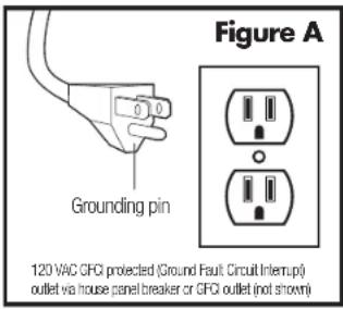
text_image
Figure A Grounding pin 120 VAC CFCI protected (Ground Fault Circuit Interrupt) outlet via house panel breaker or CFCI outlet (not shown)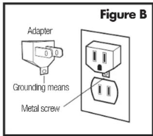
text_image
Figure B Adapter Grounding means Metal screwUse of an adapter is not allowed in Canada. If a grounding type receptacle is not available, do not use this appliance until the proper GFCI protected outlet is installed by a qualified electrician.
SAFETY INSTRUCTIONS
SAFETY INSTRUCTIONS
5
6
Important Safety Instructions
12. PERSONAL PRECAUTIONS
CAUTION
a. Consider having someone close enough or within the range of your voice to come to your aid when you work near a lead-acid battery.
b. Have plenty of soap, water and baking soda nearby in case battery acid comes in contact with skin, clothes or eyes.
c. Wear complete eye protection, hand and clothing protection. Avoid touching eyes while working near a battery.
d. If battery acid contacts skin or clothing, wash immediately with soap and water. If acid enters eye, immediately flood eye with running cold water for at least 15 minutes and get medical attention immediately.
If electrolyte is taken internally, drink large quantities of water or milk. DO NOT induce vomiting. Get prompt medical attention.
e. NEVER smoke, strike a match or cause a spark or flame in vicinity of battery or engine.
f. Be extra cautious to reduce risk of dropping a metal tool onto the battery. It might spark or short-circuit a battery or other electrical hardware which may cause an explosion or fire.
g. Remove all personal metal items such as rings, bracelets, necklaces, watches, and jewelry when working near a battery. A battery can produce a short circuit current high enough to weld a ring or any other metal, causing serious burns.
h. Use charger for charging a LEAD-ACID battery only. It is not intended to supply power to a low voltage electrical system other than in a start-motor application. Do not use battery charger for charging dry-cell batteries that are commonly used with home appliances. These batteries may burst and cause injury to persons and damage to property.
i. NEVER charge a frozen, damaged or leaking battery.
j. Keep other persons, children and pets away from batteries and your charger during operation to avoid serious injury, death, fire or explosion.
DANGER: RISK OF ELECTRIC SHOCK.
Do not touch uninsulated portion of output connector or uninsulated battery terminal
if 3 or more batteries are connected in series.
Important Safety Instructions
13. PREPARING TO CHARGE A BATTERY
CAUTION
a. If necessary to remove a battery from a boat to charge, always remove the grounded negative terminal from the battery first. Make sure all accessories in the boat are off, as to not cause an arc.
b. Be sure the area around the charger and batteries is well ventilated while the battery is being charged.
c. Neutralize with baking soda any electrolyte that spills on a vehicle or in the work area. After neutralizing, rinse contaminated area clean with water.
d. Clean battery terminals. Be careful to keep corrosion from coming in contact with eyes.
e. For flooded batteries with removable caps, ONLY ADD DISTILLED WATER in each cell until electrolyte reaches levels specified by the battery manufacturer. Do not over fill. For a maintenance free battery without removable caps, such as valve regulated lead acid batteries, carefully follow manufacturer's recharging instructions.
f. Study all battery manufacturers' specific precautions; warnings and instructions while charging and recommended rates of charge. Never charge a battery with missing safety vent caps.
g. Do not overcharge batteries trying to charge non 12 Volt flooded or AGM lead acid batteries.
SAFETY INSTRUCTIONS
GENERAL OVERVIEW
7
8
Charger Location & DC Connection
14. CHARGER LOCATION
CAUTION
a. Locate charger as far away from batteries as possible.
b. Never place a charger directly above a battery being charged; gases or fluids from battery will corrode and damage charger.
c. Do not operate charger in an enclosed area or in an area with restricted ventilation in any way.
d. Never allow battery acid to drip on charger when reading electrolyte specific gravity or filling a battery.
e.Do not set a battery on top of charger.
f. Do not install on or over combustible surfaces.
15. DC CONNECTION PRECAUTIONS
CAUTION
a. Connect and disconnect DC output cables only after removing AC cord from electric outlet. Never allow cables to touch each other.
General Overview
The new Guest® ChargePro™ On-Board Marine Battery Charger series has been fully redesigned and incorporates new features not seen in prior generations.
Every Guest ^® charger is fully automatic and has dedicated battery charging, sensing and control per bank. Designed to maximize individual battery performance, extend battery life and keep you on the water longer. The easy to read LED user display indicates the status of each battery bank through the charging process.
Notably different: The new ChargePro™ Series boasts a low profile flangeless extruded aluminum housing which is sealed with molded gaskets and heavy duty end caps for 100% waterproof performance to IP67. This new construction design delivers an increase in charging and thermal management performance. The new ChargePro™ Series is up to 40% lighter while increasing durability and ease of installation over prior generations of older technology epoxy filled plastic body chargers.
Available in 8 models for 12, 24, 36 and 48 volt systems (model specific).
Standard Features Include:
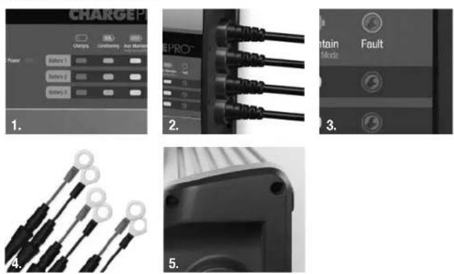
- Expanded LED display
- Heavy duty strain relief
- Wiring and battery fault status
-
In-line safety fuses
-
Extruded chassis fins and raised mounting pads for increased cooling
GENERAL OPERATION
9
GENERAL OPERATION
10
General Operation
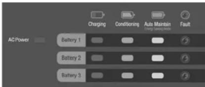
The ChargePro™ Series includes 1 blue AC Power LED with 4 LEDs per battery bank with the following functions:
text_image
Charging Conditioning Auto Maintain Fault AC Power Battery 1 Battery 2 Battery 3Note: Battery and wrench icons shown above the LEDs are print graphics only and do not have LEDs behind them. They are shown to visually represent what mode the charger is in during the charge process. The LED's below indicate status/fault information as shown in the following table.
Blue AC Power LED: LED Illuminates blue when the charger is connected to AC power.
The following Charge Mode LEDs are for each individual battery connected and will sequentially illuminate as follows:
Red Charging LED:
Initially the red Charging LED will flash after AC power is applied, indicating the charger is in process of analyzing the wiring connections, polarity and that the battery connected is >4 VDC and is capable of accepting a charge.
If everything checks out ok the red charging LED will transition to solid ON, indicating the battery is being charged. When completed, the red Charging LED will turn OFF as the charger output enters into its conditioning mode.
Amber Conditioning LED:
The amber conditioning LED will illuminate solid ON indicating the charger output is in Conditioning mode for up to 3 hours. When completed the amber Conditioning LED with turn off.
Green Auto Maintain LED:
The green Auto Maintain (Energy Saver)LED will illuminate solid ON indicating the battery connected is fully charged and is being monitored to automatically maintain the fully charged battery during short and long term storage periods.
Red Fault LED: The red Fault LED will illuminate solid ON if there is a loose wiring connection, reverse polarity, DC over-voltage or extremely low DC voltage < 4 VDC condition that is present. For batteries < 4 VDC the battery should be removed and taken to your local battery dealer for testing prior to trying to charge the battery again. See page 26 for further trouble shooting details.
Fully Automatic Multi-Stage Performance Charging Overview
The ChargePro™ Series is designed for use with 12 Volt Flooded and AGM Lead Acid batteries.
| Battery Types | Charge Profile |
| All 12 Volt Flooded (sealed maintenance free or with vent caps) and AGM (Absorbed Glass Mat) Lead Acid Batteries. | 14.6 VDC Absorption (Conditioning) and up to 13.4 VDC Float (Auto Maintain Energy saver mode). |
Note: If you are still unsure what kind of battery(s) you have, we recommend that you contact the manufacturer of the battery(s).
After completing the installation of your new ChargePro™ On-Board Charger successfully with no wiring or connection errors, and the battery(s) connected are greater than 4 VDC, the ChargePro™ will sequentially perform the following 5-Stage Digital Performance Charging Process.
ChargePro's 5-Stage Performance Charging algorithm is fully automatic and designed to maximize battery performance and extend battery life.
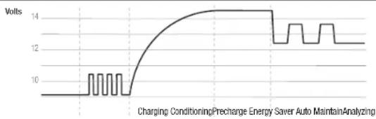
Stage 1 - Analyze Mode: AC Power is applied. ChargePro's red Charging LED will flash indicating it is analyzing individual wiring connections for proper connection/polarity and that each battery is over 4.0 VDC and capable of accepting a precharge. When completed any errors will trip a battery specific red fault LED, or if no faults are present the red Charge LED will illuminate solid red.
Stage 2 - Precharge Mode: For batteries under 10 volts, this mode is designed to pulse the battery up to 10.5 volts before accepting full rated constant current (Stage 3). During this mode the red charging LED will be illuminated with a solid on.
Stage 3 - Constant Current Charge Mode: During this mode the red charging LED will be solid on indicating each battery is being charged in constant current mode as controlled by temperature until the battery voltage is raised to 14.6 volts DC and the red Charging LED will shut off.
Stage 4 - Constant Voltage Conditioning Mode: During this mode the amber Conditioning LED will be solid on indicating each battery is being conditioned at 14.6 volts for up to 3 hours until the battery is fully charged. When completed the amber Conditioning LED with turn off and the charger will enter into Stage 5.
Stage 5 - Energy Saver Auto Maintain Mode: During this mode the blue AC Power and green Auto Maintain LED will be solid on indicating each battery is being monitored while the charger is in standby mode consuming little to no power until the battery drops under 12.8 volts (fully charged) and the charger will turn on and auto maintain the battery in a fully charged state. This is fully automatic and safe for short and long term storage.
Note: The above applies to each individual charging output. Timing of LED status will vary from battery to battery based on discharge state of the battery connected.
Charge Profile
line
| Time | Volts | |------|-------| | 0 | 0 | | 1 | 10 | | 2 | 10 | | 3 | 10 | | 4 | 10 | | 5 | 10 | | 6 | 10 | | 7 | 10 | | 8 | 10 | | 9 | 10 | | 10 | 10 | | 11 | 10 | | 12 | 10 | | 13 | 10 | | 14 | 14 | | 15 | 14 | | 16 | 14 | | 17 | 14 | | 18 | 14 | | 19 | 14 | | 20 | 14 | | 21 | 14 | | 22 | 14 | | 23 | 14 | | 24 | 14 | | 25 | 14 | | 26 | 14 | | 27 | 14 | | 28 | 14 | | 29 | 14 | | 30 | 14 | | 31 | 14 | | 32 | 14 | | 33 | 14 | | 34 | 14 | | 35 | 14 | | 36 | 14 | | 37 | 14 | | 38 | 14 | | 39 | 14 | | 40 | 14 | | 41 | 14 | | 42 | 14 | | 43 | 14 | | 44 | 14 | | 45 | 14 | | 46 | 14 | | 47 | 14 | | 48 | 14 | | 49 | 14 | | 50 | 14 | | 51 | 14 | | 52 | 14 | | 53 | 14 | | 54 | 14 | | 55 | 14 | | 56 | 14 | | 57 | 14 | | 58 | 14 | | 59 | 14 | | 60 | 14 | | 61 | 14 | | 62 | 14 | | 63 | 14 | | 64 | 14 | | 65 | 14 | | 66 | 14 | | 67 | 14 | | 68 | 14 | | 69 | 14 | | 70 | 14 | | 71 | 14 | | 72 | 14 | | 73 | 14 | | 74 | 14 | | 75 | 14 | | 76 | 14 | | 77 | 14 | | 78 | 14 | | 79 | 14 | | 80 | 14 | | 81 | 14 | | 82 | 14 | | 83 | 14 | | 84 | 14 | | 85 | 14 | | 86 | 14 | | 87 | 14 | | 88 | 14 | | 89 | 14 | | 90 | 14 | | 91 | 14 | | 92 | 14 | | 93 | 14 | | 94 | 14 | | 95 | 14 | | 96 | 14 | | 97 | 14 | | 98 | 14 | | 99 | 14 | | Note: The actual values for 'Charging Conditioning' and 'Precharge Energy' are not provided in the code. The actual values are not explicitly labeled in the code.INSTALLATION
11
Installation
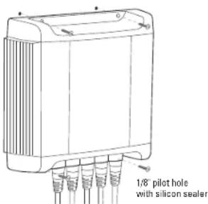
ChargePro™ 5 through 20 Amp Battery Charger models are designed to be permanently mounted on-board, and can be mounted vertically or horizontally. The ChargePro™ 10/10/10 30 Amp Triple and the 10/10/10/10 40 Amp Quad must be mounted vertically.
Always mount your ChargePro™ Series in a compartment area that can be properly ventilated during use.
Do NOT mix battery types on-board. All batteries should be of the same age and in good operating condition.
Do NOT make any electrical connections to the ChargePro™ Series or batteries until the following steps are completed:
11 Easy to follow installation steps:
- Select a flat mounting location that allows for free air ventilation with a minimum of 6 inches of clear unobstructed space around and in front of the ChargePro™ Series On-Board Marine Battery Charger. Open all battery and engine compartments and ventilate for at least 15 minutes before starting the installation of the ChargePro™ Series charger. Confirm all battery cables can reach each of the batteries.
- Do not install charger on carpeted, upholstered, vinyl, or varnished areas. Be sure to place the ChargePro™ Series in an accessible area where all indicators are viewable. Install this unit on a hard surface.
- Using the ChargePro™ Series or the enclosed template, mark the position of each mounting hole. Insure the mounting screws will not puncture or protrude into a live well, a fuel or oil tank or the bottom of the boat.
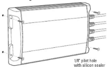
- Using a 1/8" drill bit, drill pilot holes in the (4) marked locations as described in step 3. Apply a silicon sealer in each of the mounting locations to waterproof the screw holes.
- Position the ChargePro™ Series over the mounting holes and secure with a power screwdriver by installing 4 stainless steel # 10 screws. (mounting screws included)
ChargePro™ 5, 8, 10, 15 and 20 Amp horizontal mounting
IMPORTANT NOTICE
Confirm the surface you will be mounting the charger to is adequate in strength and thickness to hold the ChargePro™ Series in place with the mounting screws you have selected.
Maintain an obstruction free area of 6 inches around the ChargePro™ Series On-Board Marine Battery Charger
text_image
1/8" pilot hole with silicon sealerINSTALLATION
12
Installation Continued
ChargePro™ 30 and 40 Amp vertical mounting
IMPORTANT NOTICE
Confirm the surface you will be mounting the charger to is adequate in strength and thickness to hold the ChargePro™ Series in place with the mounting screws you have selected.
Maintain an obstruction free area of 6 inches around the ChargePro™ Series On-Board Marine Battery Charger
text_image
1/8" pilot hole with silicon sealer- Prepare each battery in advance by cleaning each terminal post with a wire brush until a shiny surface is obtained.
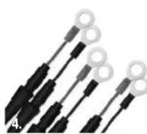
- Run cables free from sharp objects and hold each in place with cable ties. Coil excess cable, do not cut or shorten the length of the cables, as in-line fuses are located 4 inches from the end of each red (positive) cable. In addition, there are fuses in all but one of the black (negative) leads. These fuses protect the charger and output cables in the event of a short or reverse polarity. We recommend the use of wire ties or cable clamps to provide strain relief for the cables and to reduce the risk of damage to the cables or connections.
- Connect the DC output cables as illustrated on pages 14-23. Make sure the (black) wires are connected as illustrated to the negative side of the battery and the red wires are connected to the positive side of the battery.
Important Note: Your ChargePro™ Series charger will not operate properly if it is not connected properly to each battery. Reminder, each DC jacketed bank cable must be properly connected to "individual 12V batteries". Number of DC jacketed bank cables equals the number of batteries that must be individually connected. Example: a 3 bank ChargePro™ Series must be connected to 3 individual 12V batteries, as illustrated on pages 14-23. Simply choose the illustration that has the same number of charger output bank cables as your ChargePro™ Series Battery Charger in hand and wire exactly as shown (choose the illustration that matches your application) for proper charger operation
- Make sure all DC connections are correct, tight, and free from corrosion.
- Locate the AC power cord in an open-air area of your boat at least 24 inches from the charger, batteries, and fuel fill lines.
- Connect a heavy duty UL approved extension cord to the ChargePro™ Series charger first. After connecting the extension cord to the charger, proceed to plug the extension cord to a nearby 120VAC GFCI protected (Ground Fault Circuit Interrupt) outlet. Always remove the extension cord from the 120VAC outlet first when charging is completed, followed by unplugging the charger. You are now connected and charging your batteries, and can view the LED indicators.
INSTALLATION
TYPICAL WIRING
13
14
Wiring your ChargePro™ Series Charger Correctly
Simply choose the illustration that has the same number of charger output banks as your ChargePro™ Series Battery Charger and matches your application. Then wire exactly as shown for proper charger operation.
Incorrect wiring can result in reverse polarity, in the event this happens, the ChargePro™ Series has been designed to not fail as a result. Reverse polarity will cause the charger to "internally disconnect" and provide "no output" until the (reverse polarity) is corrected. A reverse polarity is caused by putting the "Red" + lead on a - negative battery terminal and/or a "Black" - lead on a + positive battery terminal. In the event of miswired battery(s), the charger will illuminate a red battery trouble status LED for the specific battery requiring attention.
Installation
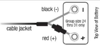
When connecting each jacketed battery charger cable, make sure it is connected to only one 12 VDC battery and observe the polarity and color of all connections:
Red Wire = + (Positive) Battery connection
Black Wire = - (Negative) Battery connection
The black wire can never be connected to a terminal with red wires. Only black.
Important: The pair of red and black wires in 1 cable jacket MUST GO TO THE SAME 12 VDC battery.
Each charger cable must be connected to 1 battery, just as shown. Observe black to (-) and red to (+). Do this for each battery.
text_image
black (-) cable jacket red (+) Group size 24 thru 31 only Top View of BatteryWhen connecting to an engine start battery connect the battery bank cable 1 that is LABELED: "Use on Engine Battery 1".
If there are more charger outputs than batteries, then a set of leads can be taped off until needed for an additional battery.
Note: ChargePro™ Series Waterproof Marine Battery Chargers are designed for any combination of group 24, 27, 29, 30 and 31 batteries. Each battery charger DC output cable must be connected to one (1) 12 Volt DC battery (even if batteries are configured for 24 Volt DC or 36 Volt DC trolling motor or system applications). Most specifically you do not have to remove series or parallel jumper cables to use your ChargePro™ Series Charger. See typical wiring diagrams for these systems in the installation section of this manual.
Note: The ChargePro™ Series must be connected to batteries to operate. It will not operate as a 12 volt power supply.
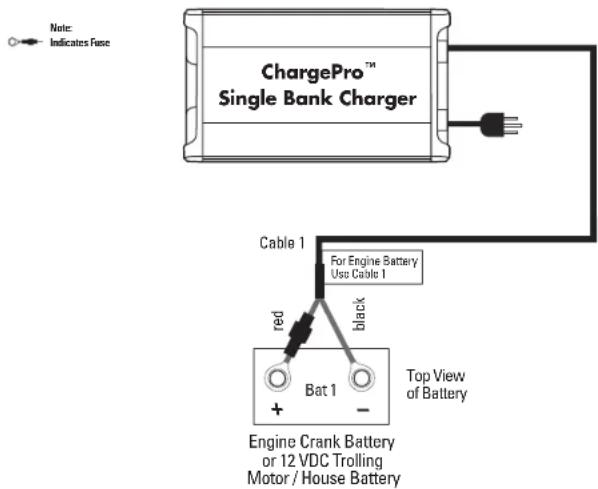
Fig. 1 ChargePro™ 5 and 10 Single Bank Charger for 1 12V Battery
Dedicated 12 VDC Trolling Motor, House or Engine Battery Configuration
text_image
Note: Indicates Fuse ChargePro™ Single Bank Charger Cable 1 For Engine Battery Use Cable 1 red black Bat 1 Top View of Battery Engine Crank Battery or 12 VDC Trolling Motor / House BatteryInstallation
When connecting each jacketed battery charger cable, make sure it is connected to only one 12 VDC battery and observe the polarity and color of all connections:
Red Wire = + (Positive) Battery connection
Black Wire = - (Negative) Battery connection
The black wire can never be connected to a terminal with red wires. Only black.
Important: The pair of red and black wires in 1 cable jacket MUST GO TO THE SAME 12 VDC battery.
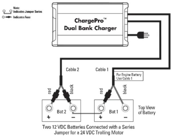
Fig. 2 ChargePro™ 4/4, 5/5 and 10/10 Dual Bank Charger for 2 12V Batteries
Dedicated 24 VDC Trolling Motor Battery Configuration with (2) 12 VDC Batteries Connected with a Series Jumper
text_image
ChargePro™ Dual Bank Charger Cable 2 Cable 1 For Engine Battery Use Cable 1 Red black Bat 2 - Top View of Battery Two 12 VDC Batteries Connected with a Series Jumper for a 24 VDC Trolling MotorInstallation
When connecting each jacketed battery charger cable, make sure it is connected to only one 12 VDC battery and observe the polarity and color of all connections:
Red Wire = + (Positive) Battery connection
Black Wire = - (Negative) Battery connection
The black wire can never be connected to a terminal with red wires. Only black.
Important: The pair of red and black wires in 1 cable jacket MUST GO TO THE SAME 12 VDC battery.
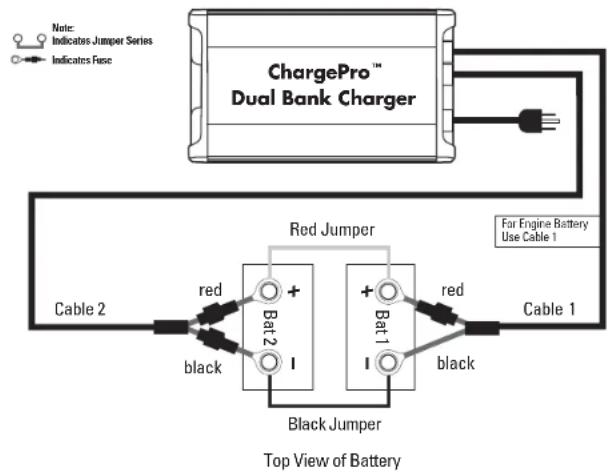
Fig. 3 ChargePro™ 4/4, 5/5 and 10/10 Dual Bank Charger for 2 12V Batteries
Dedicated 12 VDC Parallel Trolling Motor or House Configuration
flowchart
graph TD
    A["ChargePro™ Dual Bank Charger"] -->|Red Jumper| B["Black Jumper"]
    A -->|Red Jumper| C["Cable 1"]
    B -->|Black Jumper| D["Cable 2"]
    C -->|Black Jumper| E["Cable 1"]
    style A fill:#f9f,stroke:#333
    style B fill:#ccf,stroke:#333
    style C fill:#cfc,stroke:#333
Installation
When connecting each jacketed battery charger cable, make sure it is connected to only one 12 VDC battery and observe the polarity and color of all connections:
Red Wire = + (Positive) Battery connection
Black Wire = - (Negative) Battery connection
The black wire can never be connected to a terminal with red wires. Only black.
Important: The pair of red and black wires in 1 cable jacket MUST GO TO THE SAME 12 VDC battery.
Fig. 4 ChargePro™ 4/4, 5/5 and 10/10 Dual Bank Charger for 2 12V Batteries
12 VDC Trolling Motor or House Battery Configuration with a Dedicated 12 VDC Engine Start Battery
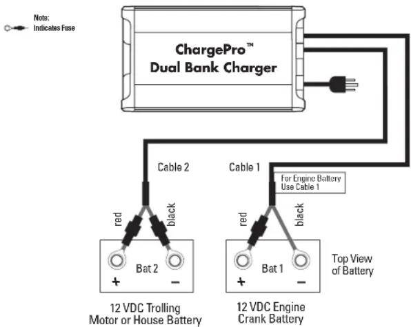
text_image
ChargePro™ Dual Bank Charger Cable 2 Cable 1 For Engine Battery Use Cable 1 red black 12 VDC Trolling Motor or House Battery Bat 2 - Top View of Battery Bat 1 -Installation
When connecting each jacketed battery charger cable, make sure it is connected to only one 12 VDC battery and observe the polarity and color of all connections:
Red Wire = + (Positive) Battery connection
Black Wire = - (Negative) Battery connection
The black wire can never be connected to a terminal with red wires. Only black.
Important: The pair of red and black wires in 1 cable jacket MUST GO TO THE SAME 12 VDC battery.
Fig. 5 ChargePro™ 5/5/5 and 10/10/10 Triple Bank Charger for 3 12V Batteries
Dedicated 12 VDC Trolling Motor or House Battery and 2 Engine Crank Batteries Typical Configuration
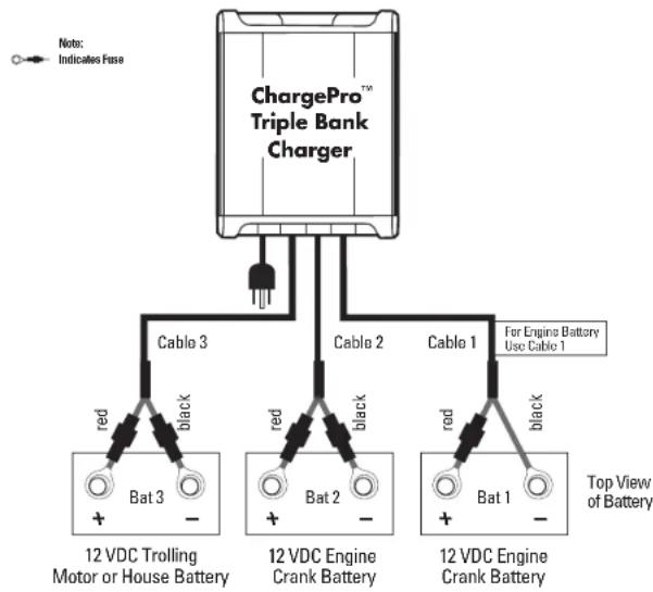
flowchart
graph TD
    A["ChargePro™ Triple Bank Charger"] -->|Cable 3| B["12 VDC Trolling Motor or House Battery"]
    A -->|Cable 2| C["12 VDC Engine Crank Battery"]
    A -->|Cable 1| D["12 VDC Engine Crank Battery"]
    B --> E["Red: Bat 3"]
    C --> F["Red: Bat 2"]
    D --> G["Red: Bat 1"]
    style A fill:#f9f,stroke:#333
    style B fill:#ccf,stroke:#333
    style C fill:#ccf,stroke:#333
    style D fill:#ccf,stroke:#333
Installation
When connecting each jacketed battery charger cable, make sure it is connected to only one 12 VDC battery and observe the polarity and color of all connections:
Red Wire = + (Positive) Battery connection
Black Wire = - (Negative) Battery connection
The black wire can never be connected to a terminal with red wires. Only black.
Important: The pair of red and black wires in 1 cable jacket MUST GO TO THE SAME 12 VDC battery.
Fig. 6 ChargePro™ 5/5/5 and 10/10/10 Triple Bank Charger for 3 12V Batteries
24 VDC Trolling Motor or House Battery Configuration with (2) 12 VDC Batteries Connected with a Series Jumper Plus Dedicated 12 VDC Engine Start Battery
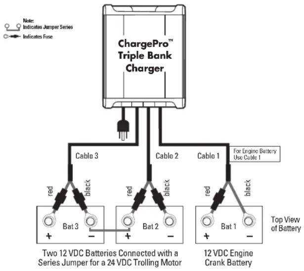
flowchart
graph TD
    A["ChargePro™ Triple Bank Charger"] -->|Red/Black/Red/Cable 3/Cable 2/Cable 1| B["Two 12 VDC Batteries Connected with a Series Jumper for a 24 VDC Trolling Motor"]
    A -->|Red/Black/Red/Cable 1/2/3/4/5/6/7/8/9/10/11/12/13/14/15/16/17/18/19/20/21/22/23/24/25/26/27/28/29/30/31/32/33/34/35/36/37/38/39/40/41/42/43/44/45/46/47/48/49/50/51/52/53/54/55/56/57/58/59/60/61/62/63/64/65/66/67/68/69/70/71/72/73/74/75/76/77/78/79/80/81/82/83/84/85/86/87/88/89/90/91/92/93/94/95/96/97/98/99| P["Top View of Battery"]
Installation
When connecting each jacketed battery charger cable, make sure it is connected to only one 12 VDC battery and observe the polarity and color of all connections:
Red Wire = + (Positive) Battery connection
Black Wire = - (Negative) Battery connection
The black wire can never be connected to a terminal with red wires. Only black.
Important: The pair of red and black wires in 1 cable jacket MUST GO TO THE SAME 12 VDC battery.
Fig. 7 ChargePro™ 5/5/5 and 10/10/10 Triple Bank Charger for 3 12V Batteries
Dedicated 36 VDC Trolling Motor Battery Configuration with (3) 12 VDC Batteries Connected with (2) Series Jumpers
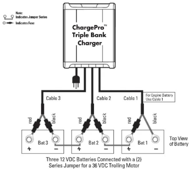
flowchart
graph TD
    A["ChargePro™ Triple Bank Charger"] -->|Cable 3| B["Three 12 VDC Batteries Connected with a (2) Series Jumper for a 36 VDC Trolling Motor"]
    A -->|Cable 2| B
    A -->|Cable 1| B
    B -->|red, black, red, black, red, black, red, black, black, red, black, black, plus/minus, plus/minus, plus/minus, plus/minus, plus/minus, plus/minus, plus/minus, plus/minus, plus/minus, plus/minus, plus/minus, plus/minus, plus/minus, plus/minus, plus/minus, plus/minus, plus/minus, plus/minus, plus/minus, plus/minus, plus/minus, plus/minus, plus/minus, plus/minus, plus/minus, plus/unknown]
    B -->|+/-| B
Installation
When connecting each jacketed battery charger cable, make sure it is connected to only one 12 VDC battery and observe the polarity and color of all connections:
Red Wire = + (Positive) Battery connection
Black Wire = - (Negative) Battery connection
The black wire can never be connected to a terminal with red wires. Only black.
Important: The pair of red and black wires in 1 cable jacket MUST GO TO THE SAME 12 VDC battery.
⚠️ DANGER: RISK OF ELECTRIC SHOCK.
Do not touch uninsulated portion of output connector or uninsulated battery terminal if 3 or more batteries are connected in series.
Fig. 8 ChargePro™ 10/10/10/10 Quad Bank Charger for 4 12V Batteries
36 VDC trolling motor battery configuration with (3) 12 VDC batteries connected with (2) series jumpers plus dedicated 12 VDC engine start battery
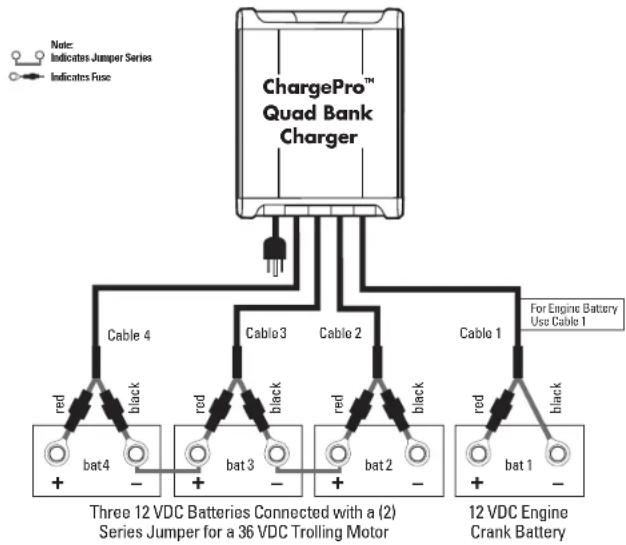
flowchart
graph TD
    A["ChargePro™ Quad Bank Charger"] --> B["Cable 4"]
    A --> C["Cable 3"]
    A --> D["Cable 2"]
    A --> E["Cable 1"]
    B --> F["Three 12 VDC Batteries Connected with a (2) Series Jumper for a 36 VDC Trolling Motor"]
    C --> G["Three 12 VDC Batteries Connected with a (2) Series Jumper for a 36 VDC Trolling Motor"]
    D --> H["Three 12 VDC Engine Crank Battery"]
    E --> I["Three 12 VDC Engine Crank Battery"]
    style A fill:#f9f,stroke:#333
    note right of A: Notes: Indicates Jumper Series; Indicates Fuse
    note right of B: Red = red, Black = black
    note right of C: Red = red, Black = black
    note right of D: Red = red, Black = black
    note right of E: Red = red, Black = black
Installation
When connecting each jacketed battery charger cable, make sure it is connected to only one 12 VDC battery and observe the polarity and color of all connections:
Red Wire = + (Positive) Battery connection
Black Wire = - (Negative) Battery connection
The black wire can never be connected to a terminal with red wires. Only black.
Important: The pair of red and black wires in 1 cable jacket MUST GO TO THE SAME 12 VDC battery.
⚠️ DANGER: RISK OF ELECTRIC SHOCK.
Do not touch uninsulated portion of output connector or uninsulated battery terminal if 3 or more batteries are connected in series.
Fig. 9 ChargePro™ 10/10/10/10 Quad Bank Charger for 4 12V Batteries
Dedicated 24 VDC trolling/house bank and 2 engine crank batteries typical configuration
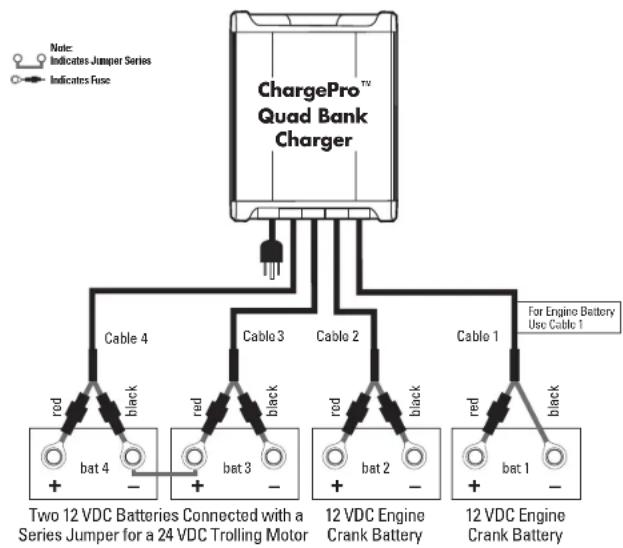
flowchart
graph TD
    A["ChargePro™ Quad Bank Charger"] -->|Cable 4, Cable 3, Cable 2, Cable 1| B["Two 12 VDC Batteries Connected with a Series Jumper for a 24 VDC Trolling Motor"]
    A -->|Cable 4, Cable 3, Cable 2, Cable 1| C["12 VDC Engine Crank Battery"]
    A -->|Cable 4, Cable 3, Cable 2, Cable 1| D["12 VDC Engine Crank Battery"]
    A -->|Cable 4, Black, red, black, red, black, red, black, red, black| E["Note: Indicates Jumper Series; Indicates Fuse"]
Installation
When connecting each jacketed battery charger cable, make sure it is connected to only one 12 VDC battery and observe the polarity and color of all connections:
Red Wire = + (Positive) Battery connection
Black Wire = - (Negative) Battery connection
The black wire can never be connected to a terminal with red wires. Only black.
Important: The pair of red and black wires in 1 cable jacket MUST GO TO THE SAME 12 VDC battery.
Fig. 10 ChargePro™ 10/10/10/10 Quad Bank Charger for 4 12V Batteries
Dedicated 48 VDC propulsion system battery configuration with (4) 12 VDC batteries connected with (3) series jumpers
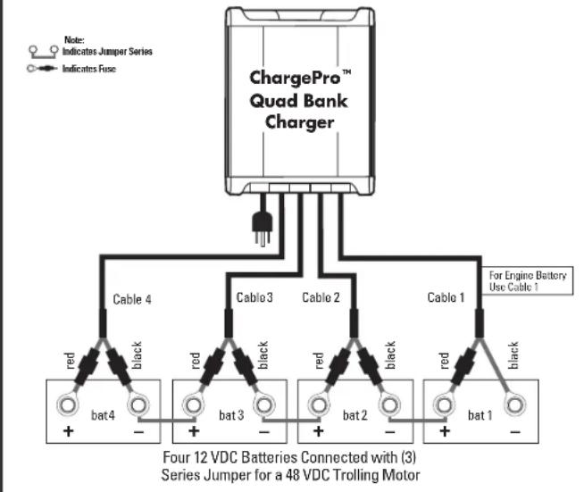
flowchart
graph TD
    A["ChargePro™ Quad Bank Charger"] --> B["Cable 4"]
    A --> C["Cable 3"]
    A --> D["Cable 2"]
    A --> E["Cable 1"]
    B --> F["red bat4 +"]
    B --> G["black bat4 -"]
    C --> H["red bat3 +"]
    C --> I["black bat3 -"]
    D --> J["red bat2 +"]
    D --> K["black bat2 -"]
    E --> L["red bat1 +"]
    E --> M["black bat1 -"]
    N["Four 12 VDC Batteries Connected with (3) Series Jumper for a 48 VDC Trolling Motor"] --> A
    N --> O["Indicates Jumper Series Indicates Fuse"]
    P["For Engine Battery Use Cable 1"] --> A
Installation
When connecting each jacketed battery charger cable, make sure it is connected to only one 12 VDC battery and observe the polarity and color of all connections:
Red Wire = + (Positive) Battery connection
Black Wire = - (Negative) Battery connection
The black wire can never be connected to a terminal with red wires. Only black.
Important: The pair of red and black wires in 1 cable jacket MUST GO TO THE SAME 12 VDC battery.
DANGER: RISK OF ELECTRIC SHOCK.
Do not touch uninsulated portion of output connector or uninsulated battery terminal if 3 or more batteries are connected in series.
Charging Your Batteries
The ChargePro™ Series is designed to charge, condition, and auto maintain your batteries during short or long term periods of storage. Please follow these steps each time you use your ChargePro™ Series Charger:
- Read manual and all warnings.
- Review "Preparing to Charge a Battery" on page 6.
- Ensure charger is installed as per the installation instructions.
- Connect a heavy duty UL approved extension cord to the ChargePro™ Series charger first. After connecting the extension cord to the charger, proceed to plug the extension cord to a nearby 120 VAC GFCI protected (Ground Fault Circuit Interrupt) outlet. Anytime power is applied to the ChargePro™ Series the blue AC Power LED will illuminate.
- The red Charge LED for each battery bank will flash indicating the charger is in Analyze mode. It should be noted, Analyze mode can take up to 1 minute as the ChargePro™ will do a self test to check wiring connections and make sure the batteries are > than 4 Volts DC and are able to take a charge.
Assuming there are no battery faults, the following charger operation sequences will proceed:
Note: If there is a bad connection, reverse polarity, or a battery that is below 4 VDC that can not accept a charge then a RED Battery Trouble status LED will illuminate for the battery that requires attention. See page 26 for further troubleshooting details.
6. The red charge mode LED for each battery bank will transition to a solid ON indicating the charger has started its multi-stage charging process as outlined in the Multi-Stage Charging Overview section of this manual.
CAUTION HOT SURFACE. Avoid contact during charging operation as unit will be hot to the touch but operating safely and properly.
7. The red Charging mode LED for each battery bank will turn off and the Conditioning LED will be solid amber indicating that the ChargePro™ will hold all batteries at 14.6 VDC to complete charging by conditioning each battery for up to 3 hours as needed.
8. When the charge process is complete (or if your batteries are fully charged when you apply AC power) the green Auto Maintain (Energy Saver Mode) LED for each battery bank will illuminate indicating your batteries are fully charged.
Note: The above applies to each individual charging output. Timing of LED status will vary from battery to battery based on discharge state of the battery connected.
MAINTENANCE
25
TROUBLESHOOTING
26
Owner's Periodic Maintenance Guide
| Item:Process:When: | Battery ConnectionsClean and tighten all battery connections. Follow battery manufacturer's instructions for cleaning a battery. Clean all battery terminals with a wire brush where required and tighten all battery connections.Monthly |
| Item:Process:When: | Battery ElectrolytePer battery manufacturer's Instructions, monitor, and maintain proper levels of distilled water in each battery.Monthly |
| Item:Process:When: | DC Output WiringVisually inspect all wiring for cuts and abrasions. Contact Guest® if your ChargePro® On-Board Marine Battery Charger needs to be serviced.Monthly |
| Item:Process:When: | AC Power CordVisually inspect the AC power cord. Confirm ground blade is present and all plug blades are in good condition and not bent out of place.Monthly |
| Item:Process:When: | Mounting Hardware InspectionCheck all mounting hardware to ensure there is no loose hardware.Tighten where required.Monthly |
Troubleshooting
No Blue AC Power LED or Charge Mode LEDs
Check for loss of AC power at the 120 VAC outlet. Confirm GFCI (Ground Fault Circuit Interrupter) has not tripped. Check with a meter or 120 VAC test light that AC power is present at the end or your extension cord. Reset AC power if it was not present. Confirm all charger cables are installed with the correct polarity connections at each battery and that all connections are clean and tight. Wait 1 minute while unit completes its analyze mode. If AC power is present and all connections are correct and LEDs do not illuminate, contact Guest® ChargePro™ Factory Service at 1-800-824-0524 from 8:30 am to 5pm Eastern Time. If your ChargePro™ Series is within the warranty period of 2 years from the date of purchase, you can go to www.chargepro.com where you will find our customer care return form and instructions.
Red Battery Bank Trouble Status LED is ON.
Identify the battery bank LED that is lit, remove AC power and check the battery bank indicated i.e 1, 2, 3 or 4 (model specific). The LED indicates there is a fault present. Listed below are typical faults and what can be done to clear the red battery bank trouble status indicator (reapply AC power after making any corrections):
Poor battery connections - Make sure all connections are tight and clean
Blown DC cable fuse - Make sure all fuses are good with a digital ohm meter or continuity tester and visually inspect the ChargePro™ Series's DC battery cables to insure they have not been compromised or shorted in any way.
Reverse polarity - Make sure all wiring connections are color coded and connected properly and that each bank cable goes to one 12V battery where (+) = red and (-) = black.
Battery too low to charge - with a digital voltmeter make sure the battery is over 4.0 volts DC (if not have your battery charged out of the boat and have it load tested by your local battery dealer to insure it is safe to charge and that the battery is capable of holding a charge).
High battery voltage input - Check to make sure one bank lead was not spread across 2 batteries connected in series for 24 volts DC. If so correct by wiring to the diagrams on pages 14-23.
Battery(s) not charging, Blue AC Power LED, RED Charging LED is ON
Confirm all charger cables are installed with the correct polarity connections at each battery, and that all connections are clean and tight. Confirm that there are no bank trouble status LED indicators on. With the charger on, read DC voltage at each battery. If any of the readings are less than 12.8 volts DC proceed with the following:
A. Disconnect AC power at the 120 VAC outlet.
B. Go to pages 14-23 of this manual and confirm your ChargePro™ Series model charger is connected correctly as illustrated in the installation drawings.
C. Upon completing B above; plug your charger into AC power and observe the LED display. Charger should be in the charging mode (charge mode indicator should be red). After completing a full charge cycle, 10-12 hours or more for deeply discharged or completely dead batteries, the green Auto Maintain LED will illuminate in addition to the blue AC Power LED
Note: If a Digital Volt Motor (DVM) is available to you, instead of waiting to complete a full charge cycle, you can simply use a DVM and take DC voltage measurements across each 12 volt battery. As long as the voltage continues to increase while the red charging LED is on, this will serve as a confirmation that the charger is properly connected and is properly charging.
WARRANTY
ChargePro™ On-Board Marine Battery Charger Warranty
We are committed to customer satisfaction and value your business. If at any time during the warranty period you experience a problem with your new ChargePro™ On-Board Marine Battery Charger, simply call us at 1-800-824-0524 between 8:30am-5pm (EST) Monday through Friday, for technical support or email info@chargepro.com
WARRANTY CARD CAN BE REGISTERED AT WWW.CHARGEPRO.COM or the warranty card included in this manual can be completed and sent to Guest® by mail.
GUEST® CHARGEPRO™ ON-BOARD MARINE BATTERY CHARGER LIMITED TWO-YEAR FACTORY WARRANTY
Each ChargePro™ On-Board Marine Battery model is guaranteed against defects in material and workmanship to the original consumer in normal use for 2 years from the date of purchase. Guest® will at it's discretion repair or replace free of charge any defects in material or workmanship.
The following conditions apply:
- Warranty and repair adjustment calculated from manufacture date if not registered or proof of purchase within two weeks of sale.
- Warranty void if unauthorized repairs attempted.
- Warranty void for water submersion and intrusion.
- Customer is responsible for shipping return unit to the Guest® factory service center listed below.
- Cosmetic repairs are done at the owner's request and expense.
Purchase or other acceptance of the product shall be on the condition and agreement that Guest® SHALL NOT BE LIABLE FOR INCIDENTAL OR CONSEQUENTIAL DAMAGES OF ANY KIND. (Some states do not allow the exclusion or limitation of incidental or consequential damages, so the above limitations may not apply to you.) This warranty is made in lieu of all other obligations or liabilities on the part of Guest®. Guest® neither assumes nor authorizes any person for any obligation or liability in connection with the sale of this product.
To make a claim under warranty, go to www.chargepro.com and click on the resources tab and follow the instructions making sure to identify the product and the problem. If you can not use our online warranty claim registration, please feel free to call the Guest ^® factory service center at the toll free number listed below. Guest ^® will make its best effort to repair or replace the product, if found defective within the terms of the warranty, within 30 days after return of the product to the company. Guest ^® will ship the repaired or replaced product back to the purchaser. This warranty gives you specific legal rights, and you may also have other rights, which vary from state to state or province to province. This warranty is in lieu of all others expressed or implied.
Guest® ChargePro™
Factory Service Center & Technical Support
15 Dartmouth Drive, STE 101
Auburn, New Hampshire 03032.
USA TOLL FREE: 1-800-824-0524
Tel: (603) 433-4440 / Fax: (603) 433-4442
Visit us on the web at: www.chargepro.com

CHARGEUR DE BATTERIE NAUTIQUE EMBARQUÉ
CHARGEPRO™
text_image
GUEST MACHINE BATTERY CHARGER 515 33 AMP THIPS2 80W MAXIMUM OF 7.0V AC/DC POWER: 60kW (400V AC/DC) CHARGEPRO® S/12 S/13 S/14 S/15 S/16 S/17 S/18 S/19 S/20 S/21 S/22 S/23 S/24 S/25 S/26 S/27 S/28 S/29 S/30 S/31 S/32 S/33 S/34 S/35 S/36 S/37 S/38 S/39 S/40 S/41 S/42 S/43 S/44 S/45 S/46 S/47 S/48 S/49 S/50 S/51 S/52 S/53 S/54 S/55 S/56 S/57 S/58 S/59 S/60 S/61 S/62 S/63 S/64 S/65 S/66 S/67 S/68 S/69 S/70 S/71 S/72 S/73 S/74 S/75 S/76 S/77 S/78 S/79 S/80 S/81 S/82 S/83 S/84 S/85 S/86 S/87 S/88 S/89 S/90 S/91 S/92 S/93 S/94 S/95 S/96 S/97 S/98 S/99 S/T00
100 % Étanche
Garantie de 2 ans

Factory Service and Technical Support
15 Dartmouth Drive, STE 101
Auburn, New Hampshire 03032
603-433-4440
1-800-824-0524
www.chargepro.com
Fabriqué en Chine
text_image
CHARGE Power Battery 1 Battery 2 Battery 3 Charging Griding Auto Mountion 1.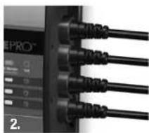
natural_image
Close-up of black USB cable connectors with labels, no readable text or symbols beyond component identifiers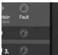
natural_image
Close-up of multiple black and gray electrical connectors with circular ends (no text or symbols visible)
natural_image
Close-up of a black mechanical component with ribbed top and mounting holes (no visible text or symbols)text_image
AC Power Charging Conditioning Auto Warban Fleet Battery 1 Battery 2 Battery 3Factory Service Center & Technical Support
15 Dartmouth Drive, STE 101